EP0173064A2 - Siebdruckmaschine - Google Patents
Siebdruckmaschine Download PDFInfo
- Publication number
- EP0173064A2 EP0173064A2 EP85109035A EP85109035A EP0173064A2 EP 0173064 A2 EP0173064 A2 EP 0173064A2 EP 85109035 A EP85109035 A EP 85109035A EP 85109035 A EP85109035 A EP 85109035A EP 0173064 A2 EP0173064 A2 EP 0173064A2
- Authority
- EP
- European Patent Office
- Prior art keywords
- printing
- arrangements
- stencil
- arrangement
- intended
- Prior art date
- Legal status (The legal status is an assumption and is not a legal conclusion. Google has not performed a legal analysis and makes no representation as to the accuracy of the status listed.)
- Granted
Links
- 239000000463 material Substances 0.000 claims abstract description 112
- 238000006073 displacement reaction Methods 0.000 claims abstract description 28
- 238000003780 insertion Methods 0.000 claims description 29
- 230000037431 insertion Effects 0.000 claims description 29
- 238000010276 construction Methods 0.000 description 3
- 230000032258 transport Effects 0.000 description 3
- 230000001133 acceleration Effects 0.000 description 2
- 238000010586 diagram Methods 0.000 description 2
- 239000000945 filler Substances 0.000 description 2
- 230000001105 regulatory effect Effects 0.000 description 2
- 230000009471 action Effects 0.000 description 1
- 239000011248 coating agent Substances 0.000 description 1
- 238000000576 coating method Methods 0.000 description 1
- 230000003993 interaction Effects 0.000 description 1
- 238000000034 method Methods 0.000 description 1
- 238000012986 modification Methods 0.000 description 1
- 230000004048 modification Effects 0.000 description 1
- 230000000284 resting effect Effects 0.000 description 1
Images
Classifications
-
- B—PERFORMING OPERATIONS; TRANSPORTING
- B41—PRINTING; LINING MACHINES; TYPEWRITERS; STAMPS
- B41F—PRINTING MACHINES OR PRESSES
- B41F15/00—Screen printers
- B41F15/08—Machines
- B41F15/0804—Machines for printing sheets
- B41F15/0813—Machines for printing sheets with flat screens
- B41F15/0818—Machines for printing sheets with flat screens with a stationary screen and a moving squeegee
-
- B—PERFORMING OPERATIONS; TRANSPORTING
- B41—PRINTING; LINING MACHINES; TYPEWRITERS; STAMPS
- B41P—INDEXING SCHEME RELATING TO PRINTING, LINING MACHINES, TYPEWRITERS, AND TO STAMPS
- B41P2215/00—Screen printing machines
- B41P2215/10—Screen printing machines characterised by their constructional features
Definitions
- the present invention relates to a stencil printing machine and particularly to a stencil printing machine which includes a printing table, a number of movably arranged material gripping and displacement arrangements, a stencil tensioned in a frame and placed above the printing table and a doctor blade arrangement which can interact with the stencil.
- the gripper beams include members for gripping and displacing a material.
- the gripper beams interact with at least one,preferably two, endless feed chains or the like, which are arranged in parallel. These cease to move when the gripper beams are located in predetermined positions, one for the gripper beam to grip a sheet or material intended for printing, and one for the gripper beam to hold or leave a sheet in a position for application of print to the sheet.
- the gripper beams can be made adjustable by means of a double lever arm system so that the gripper beams adopt precisely the said predetermined positions, by providing the end surfaces of the gripper beams and the outer ends of the double lever arm system with interacting members.
- the members comprise on the one hand convex, preferably cylindrical or spherical surfaces and secondly preferably "V"-shaped recesses which are intended to be pressed against each other in the predetermined position.
- the material intended for printing can either be taken automatically from an inserter or direct from a feed stack so as to be gripped by the gripper beam, or else the material can be inserted by hand and registered in an insertion position.
- the present invention relates to a stencil printing machine of the type mentioned above and which possesses the feature that at least one material gripping and displacement arrangement has imparted to it a reciprocating movement between two predetermined positions, an initial position for gripping and fetching material intended for printing and a second position for placing material which has been fetched unto the printing table, and that the position of the arrangement is registered in both the initial and the second position.
- the invention also is characterised by the fact that at least two material grippings and displacement arrangements are combined with each other, whilst at the same time these arrangements are controlled to give a reciprocating movement.
- one arrangement In an initial position one arrangement is designed to grip a first item of material intended for printing in its insertion position, and the second arrangement is intended to grip another item of material provided with print in its printing position.
- one arrangement is designed to leave the first item of material intended for printing in its printing position and the second arrangement is designed to hand over a second item of material provided with print to a delivery position.
- the invention is also characterised by the fact that the arrangements can be displaceably installed along two parallel-orientated guides, one arrangement being registered during the gripping of the material intended for printing in the insertion position, whilst the second arrangement can be registered on placing the material into the printing position.
- the invention is also characterised by the possibility of having three or more material gripping and displacement arrangements being firmly connected to each other during one reciprocating movement.
- one arrangement be designed to grip an initial item of material intended for printing in its insertion position, whilst the other arrangements are intended to each grip further items of material provided with printed image in their respective printing position.
- one arrangement is, like the remainder apart from the last, designed to .leave each of the respective items of material in its printing position, whilst the last arrangement is intended to hand over an item of material provided with printed image (multiple printing) to a delivery position.
- the invention also relates to an alternative, where the printing table will be displaceably arranged so that it can move upwards and downwards, in its upper position being capable of providing support for the material in the printing position.
- the material gripping and displacement arrangement can be raised and lowered.
- the main advantages which can be perceived as being linked with a stencil printing machine in accordance with the present invention are that the design of the gripper beams and its drive machinery can be made much more simple than with previously known machines, whilst at the same time the construction becomes light, thus permitting rapid movement of the gripper beams between different predetermined positions and this rapid displacement can take place without the consumption of large quantities of power and energy.
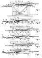
- FIG. 1 shows in side view and in greatly simplified form a stencil printing machine in accordance with the present invention.
- the stencil printing machine includes a printing table 1, two movably arranged material gripping and displacement arrangements, in the following designated as gripper beams and designated 2 and 3, a blanket 5 which is tensioned in a frame 4 unto which a stencil is applied and where this blanket is located directly above the printing table 1.
- a doctor blade and ink filling arrangement which are not shown, interact with the stencil 5.
- Fig. 1 illustrates a drive machinery 6 which is intended via an arm 6a and a further arm 6b to displace the gripper beams 2 and 3 in a reciprocating movement.
- the invention requires that at least one, in the embodiment here two, material gripping and displacement arrangements 2,3 be combined with each other, which in the embodiment shown is illustrated in that a beam 7 is fastened at one end 7a to the gripper beam 2 and at the other end 7b is attached to the gripper beam 3, by which means the gripper beams 2 and 3 can be displaced along a guide 8, to and fro, as indicated by the arrows Pl and P2 by means of a control arrangement which is not illustrated in the diagram.
- a reciprocating movement can be imparted to the gripper beam 2 between two stop positions.
- the gripping member 2a of one gripper beam 2 is designed to grip an initial item of material "A" which is located in an insertion position, in the embodiment resting on a table 9.
- the second gripper beam 3 is intended, using its gripper member 3a, to grip another item of material "B" located in a printing position and where this material is provided with a printed image in the printing position by the doctor blade arrangement being displaced along the stencil 5 and pressing printing ink which is present on the upper face of the stencil through the blanket 5 so as to form a coating or a printed image on the material "B".
- the gripper beams 2 and 3 have each gripped their material "A” and "B” the gripper beams 2 and 3 are displaced to a second position. In this position as shown in Fig.
- one of the gripper beams 2 is designed to leave the first item of material "A" intended for printing in the printing position for printing table 1, whilst the second gripper beam 3 is designed to hand over the printed material "B” to a delivery position.
- This delivery position has been given the reference notation number 10.
- the gripper beams 2 and 3 are shown joined to each other via the beam 7. It can be advisable to make the supports to 2b and 3b somewhat resilient, by this means committing the adjustment and registration of the gripper beam in its position.
- the example forming the embodiment illustrates that the insertion position 9 is orientated some distance above the printing position 1 and that the gripper beams are displaceably arranged along two parallel guides 8. However, at one end surface 8a these guides 8 can swivel to some extent around an axis 11 which means that it should be possible to impart to the gripper beam 2 a horizontal or at least essentially horizontal movement from the insertion position 9 to the printing position, this dropping downwards only in connection with the printing position so that the material can be made to rest against the printing table 1.
- the delivery position 10 should also comprise a printing table, where the printing table 1 is intended to apply an initial colour to the material "B" whilst the printing table (at 10) is provided there to apply a second colour to the same material.
- the gripper beams 2 In the first position illustrated in Fig. 1, one of the gripper beams 2 is intended to grip an initial material "A” in its insertion position 9 whilst the remaining gripper beams are intended each to grip further material in their respective printing positions. This signifies that the gripper beam 3 grips the material "B" in the printing table 1, whilst the next gripper beam (not shown) grips the material which has been printed at a printing table (not shown) located at reference notation number 10.
- one of the gripper beams 2 and the remainder, apart from the last, are each intended to leave their respective materials in their printing position.
- the last gripper beam is intended to hand over a printed material to a delivery position.
- FIG. 3 and 4 an embodiment is shown where the printing table 1 can be raised and lowered.
- the printing table 1, is shown best in Fig. 4 is supported by a parallel link system 12 and by this means the printing table can adopt a lower position as shown in Fig. 3 and an upper position as in Fig. 4.
- the printing table is located in a lower position and permits the gripper beam 2 to pass across the printing table 1 along fixed guides 8.
- gripper beam 2 adopts the position shown in Fig. 4 and the material "A" is located above the printing table 1, the printing table 1 is raised to the position illustrated in Fig. 4 and print can be applied to the material "A".
- the printing table 1 is lowered and the gripper beam 2 reverts to the position shown in Fig. 3 in order to fetch new material whilst at the same time gripper beam 3, after raising of the printing table, can grip the printed material.
- the gripper beam 3 removes the printed material from the printing table whilst gripper beam 2 locates a new item of material intended to be printed on printing table 1.
- Fig. 5 and 6 illustrate an embodiment where the gripper beams, particularly gripper beam 2, can be raised and lowered.
- the gripper beam 2 is attached to beam 7 via a system of parallel rods 13 so that as illustrated in Fig. 5 gripper beam 2 can adopt an upper position so as to grip a material "A" intended for printing.
- Gripper beam 2 adopts this upper position during its displacement along the fixed guides 8 to the printing position above printing table 1, after which gripper beam 2 is dropped down to its lower position as shown in Fig. 6 and here places the material "A" intended for printing in the printing position on the fixed printing table 1.
- the principle underlying the invention can also be utilised for one gripper beam 2. After registration, this grips in the insertion position 9 and transports the material "A" to printing table Here the gripper beam 2 is registered once again and the material is fastened to the printing table. Then the gripper beam can revert to the insertion position 9.
- This embodiment has an upper frame 4, in which the stencil is arranged and supported in a well known manner together with an ink filler and a doctor blade (not shown), which may reciprocate along the stencil and in only one direction of movement press the ink through apertures in the stencil, said apertures forming the pattern to be printed onto the material "A".
- Said frame 4 together with the ink filler and the doctor bläde and the stencil is movablg arranged up and down and so controlled in said movement that in the upper position the material "A" is transported of the gripper 2 along the printing table 1 (from the position shown in fig 3. to the position shown in figure 4). During this transportation the printing table is in its lower position.
- the frame 4 is moved to its lower position and the printing table is moved to its upper position and in these positions the printing sequence may start.
- the gripper 2 has an upper smooth surface (plane surface) lying more or less in the same plane as the material "A", when rested upon the printing table, it is possible to print the material "A" when said material is gripped by the gripper 2, and further to start the printing and its printing pattern adjacent the egde of the naterial and adjacent the gripper 2.
- the gripper 2 serves as registering device of the material on the table 1.
Landscapes
- Engineering & Computer Science (AREA)
- Mechanical Engineering (AREA)
- Screen Printers (AREA)
- Supply, Installation And Extraction Of Printed Sheets Or Plates (AREA)
- Printing Plates And Materials Therefor (AREA)
- Soil Working Implements (AREA)
- Manufacture Or Reproduction Of Printing Formes (AREA)
- Discharge By Other Means (AREA)
- Application Of Or Painting With Fluid Materials (AREA)
- Manufacturing Of Printed Wiring (AREA)
- Non-Metallic Protective Coatings For Printed Circuits (AREA)
- Printing Methods (AREA)
- Glass Compositions (AREA)
- Transition And Organic Metals Composition Catalysts For Addition Polymerization (AREA)
- Permanent Magnet Type Synchronous Machine (AREA)
- Sheets, Magazines, And Separation Thereof (AREA)
- Pile Receivers (AREA)
Priority Applications (1)
| Application Number | Priority Date | Filing Date | Title |
|---|---|---|---|
| AT85109035T ATE57135T1 (de) | 1982-01-19 | 1983-01-17 | Siebdruckmaschine. |
Applications Claiming Priority (2)
| Application Number | Priority Date | Filing Date | Title |
|---|---|---|---|
| SE8200276 | 1982-01-19 | ||
| SE8200276A SE456640B (sv) | 1982-01-19 | 1982-01-19 | Stenciltryckmaskin med hoej- och saenkbart tryckbord |
Related Parent Applications (1)
| Application Number | Title | Priority Date | Filing Date |
|---|---|---|---|
| EP83850005.6 Division | 1983-01-17 |
Publications (3)
| Publication Number | Publication Date |
|---|---|
| EP0173064A2 true EP0173064A2 (de) | 1986-03-05 |
| EP0173064A3 EP0173064A3 (en) | 1986-07-23 |
| EP0173064B1 EP0173064B1 (de) | 1990-10-03 |
Family
ID=20345769
Family Applications (5)
| Application Number | Title | Priority Date | Filing Date |
|---|---|---|---|
| EP83111078A Expired EP0109599B1 (de) | 1982-01-19 | 1983-01-17 | Siebdruckmaschine |
| EP83850005A Expired EP0085034B1 (de) | 1982-01-19 | 1983-01-17 | Siebdruckmaschine |
| EP83111076A Withdrawn EP0109597A3 (de) | 1982-01-19 | 1983-01-17 | Siebdruckmaschine |
| EP85109035A Expired - Lifetime EP0173064B1 (de) | 1982-01-19 | 1983-01-17 | Siebdruckmaschine |
| EP83111077A Expired EP0109598B1 (de) | 1982-01-19 | 1983-01-17 | Siebdruckmaschine |
Family Applications Before (3)
| Application Number | Title | Priority Date | Filing Date |
|---|---|---|---|
| EP83111078A Expired EP0109599B1 (de) | 1982-01-19 | 1983-01-17 | Siebdruckmaschine |
| EP83850005A Expired EP0085034B1 (de) | 1982-01-19 | 1983-01-17 | Siebdruckmaschine |
| EP83111076A Withdrawn EP0109597A3 (de) | 1982-01-19 | 1983-01-17 | Siebdruckmaschine |
Family Applications After (1)
| Application Number | Title | Priority Date | Filing Date |
|---|---|---|---|
| EP83111077A Expired EP0109598B1 (de) | 1982-01-19 | 1983-01-17 | Siebdruckmaschine |
Country Status (11)
| Country | Link |
|---|---|
| US (2) | US4589335A (de) |
| EP (5) | EP0109599B1 (de) |
| JP (1) | JPS591258A (de) |
| AT (3) | ATE36273T1 (de) |
| AU (1) | AU568486B2 (de) |
| BR (1) | BR8300233A (de) |
| CA (1) | CA1197138A (de) |
| DE (4) | DE3381928D1 (de) |
| ES (1) | ES8404780A1 (de) |
| SE (4) | SE456640B (de) |
| ZA (1) | ZA83165B (de) |
Cited By (3)
| Publication number | Priority date | Publication date | Assignee | Title |
|---|---|---|---|---|
| GB2203993A (en) * | 1987-04-02 | 1988-11-02 | Ake Svantesson | Silkscreen printing method and apparatus for multicolour printing |
| EP1068953A1 (de) * | 1999-06-18 | 2001-01-17 | LOSI, Bruno | Siebdruckverfahren und Siebdruckmaschine zur Durchführung des Verfahrens |
| WO2001007253A1 (en) * | 1999-07-28 | 2001-02-01 | Registerprint Machinery Limited | Printer |
Families Citing this family (19)
| Publication number | Priority date | Publication date | Assignee | Title |
|---|---|---|---|---|
| SE454256B (sv) * | 1982-05-05 | 1988-04-18 | Svecia Silkscreen Maskiner Ab | For en stenciltryckmaskin avsedd stencilram fasthallande och/eller registrerande anordning |
| SE448424B (sv) * | 1985-07-10 | 1987-02-23 | Svecia Silkscreen Maskiner Ab | Stenciltryckmaskin med ett fram och ater rorligt rakelarrangemang |
| SE454761B (sv) * | 1987-04-01 | 1988-05-30 | Svecia Silkscreen Maskiner Ab | Stenciltryckmaskin anpassad for en tryckning av ett och samma monster i tva olika och motriktade riktningar |
| SE8701392L (sv) * | 1987-04-02 | 1988-10-03 | Svecia Silkscreen Maskiner Ab | Anordning foer att i en stenciltryckmaskin paa ett material kunna applicera i tur och ordning ett flertal faerger foer att bilda paa materialet ett ett flerfaergstryck uppvisande moenster |
| SE460659B (sv) * | 1987-08-27 | 1989-11-06 | Svecia Silkscreen Maskiner Ab | Anordning foer att automatiskt och i tur och ordning kunna framstaella ett antal tryckformar |
| SE458800B (sv) * | 1987-08-28 | 1989-05-08 | Lars Tiberg | Foerfarande foer oeverfoering av vatten fraan roekgaser till foerbraenningsluft med regenerativ vaermevaexling |
| SE8703669L (sv) * | 1987-09-23 | 1989-03-24 | Svecia Silkscreen Maskiner Ab | Saett att i en flerfaergsstenciltryckmaskin kunna orientera ett material foer raett tryckning i resp trycklaege |
| DE3811143A1 (de) * | 1988-03-31 | 1989-10-12 | Eltex Elektrostatik Gmbh | Siebdruckverfahren |
| US4879948A (en) * | 1988-10-04 | 1989-11-14 | American Screen Printing Equipment Company | Press with automatic sheet transport mechanism |
| US4919043A (en) * | 1988-10-04 | 1990-04-24 | American Screen Printing Company | Web tech drive assembly for stencil carriage |
| SE463196B (sv) * | 1989-04-10 | 1990-10-22 | Svantesson Ake | Stenciltryckmaskin med rakel och stencil i motriktad roerelse |
| DE9004738U1 (de) * | 1990-04-26 | 1991-08-29 | SPS Siebdruckmaschinen GmbH, 5600 Wuppertal | Siebdruckvorrichtung mit beweglicher Tischplatte |
| DE4209991A1 (de) * | 1992-03-27 | 1993-09-30 | Hermann Horndasch | Vorrichtung zum Transport von zu bearbeitenden Teilen |
| US5301608A (en) * | 1993-06-04 | 1994-04-12 | Precision Screen Machines, Inc. | Index control system for printing apparatus |
| US5372066A (en) * | 1993-08-11 | 1994-12-13 | Becmar Corp. | Multiple feed cylinder press |
| JPH0929932A (ja) * | 1995-07-20 | 1997-02-04 | Sakurai Graphic Syst:Kk | 印刷機の搬送装置 |
| AU769258B2 (en) * | 2000-04-17 | 2004-01-22 | Reefdale Pty Ltd | Garment loader |
| AUPQ692900A0 (en) * | 2000-04-17 | 2000-05-11 | Reefdale Pty Ltd | Garment loader |
| DE102005020588A1 (de) * | 2005-05-03 | 2006-11-09 | Bayerische Motoren Werke Ag | Verbindungsanordnung |
Family Cites Families (29)
| Publication number | Priority date | Publication date | Assignee | Title |
|---|---|---|---|---|
| US836483A (en) * | 1905-02-23 | 1906-11-20 | Charles Laurence Burdick | Color-printing machine. |
| DE582325C (de) * | 1930-07-09 | 1933-08-14 | C & A Holweg | Papiertransportvorrichtung fuer Papierbeutelmaschinen |
| US2110140A (en) * | 1935-01-21 | 1938-03-08 | Process Machine Corp | Printing machine |
| GB469910A (en) * | 1936-02-06 | 1937-08-05 | Linotpye And Machinery Ltd | Improvements in or relating to sheet delivery mechanism for printing machines |
| US2609747A (en) * | 1947-11-26 | 1952-09-09 | May Hosiery Mills | Design dyeing apparatus |
| US2690118A (en) * | 1952-01-15 | 1954-09-28 | May Hosiery Mills | Design dyeing apparatus |
| US3075651A (en) * | 1961-03-07 | 1963-01-29 | Valen Mfg Co | Transfer device |
| US3180253A (en) * | 1961-04-04 | 1965-04-27 | Brock And Rankin | Multi-station embossing machines |
| GB995006A (en) * | 1962-05-11 | 1965-06-10 | Stilex Printing Ltd | Improvements in and relating to method and apparatus for transferring workpieces andin particular in printing |
| US3460470A (en) * | 1965-07-29 | 1969-08-12 | Advance Process Supply Co | Process and apparatus for multicolor screen printing |
| GB1127482A (en) * | 1966-02-14 | 1968-09-18 | Screen Printing Machinery Ltd | Screen printing machine |
| US3384070A (en) * | 1966-09-07 | 1968-05-21 | Coleman Co | Gas wall heater |
| US3812779A (en) * | 1969-05-22 | 1974-05-28 | American Screen Process Equip | Automatic multi-color printing arrangement |
| US3577914A (en) * | 1969-11-28 | 1971-05-11 | Heinrich Ronge | Screen printing machine employing a reciprocating printing and feed plate |
| US3754667A (en) * | 1972-01-07 | 1973-08-28 | R Storch | Transfer mechanism |
| DE2315950C2 (de) * | 1973-03-30 | 1982-10-07 | L. Schuler GmbH, 7320 Göppingen | Werkstücktransportvorrichtung, insbesondere für Blechteile an Pressen |
| US3861520A (en) * | 1973-04-25 | 1975-01-21 | Robert L Ballard | Transfer apparatus |
| GB1478497A (en) * | 1973-09-15 | 1977-06-29 | Forst Maschinenfab Und Apparat | Workpiece handling device in a machine tool |
| DE2349126C2 (de) * | 1973-09-29 | 1982-07-29 | Günter 7500 Karlsruhe Zierpka | Vorschubeinrichtung zum schrittweisen Material- und/oder Werkstücktransport |
| US4031824A (en) * | 1975-11-03 | 1977-06-28 | American Screen Printing Equipment Company | Sheet feed and takeoff assembly for printers |
| US4058307A (en) * | 1975-11-03 | 1977-11-15 | American Screen Printing Equipment Company | Feed and takeoff assembly |
| US4003476A (en) * | 1975-11-21 | 1977-01-18 | Benruth Engineering & Manufacturing Company, Inc. | Press Loader |
| US4032018A (en) * | 1975-11-21 | 1977-06-28 | Wallis Bernard J | Workpiece transfer mechanism |
| US4094242A (en) * | 1976-06-14 | 1978-06-13 | Shiro Ichinose | Lifting devices for flat screen printer |
| SU631363A1 (ru) * | 1976-11-09 | 1978-11-05 | Новочеркасский Ордена Трудового Красного Знамени Политехнический Институт Имени Серго Орджоникидзе | Устройство дл подачи изделий в зону печати трафаретной машины |
| SE402735B (sv) * | 1976-11-24 | 1978-07-17 | Svecia Silkscreen Maskiner Ab | Tryckerimaskin |
| US4139090A (en) * | 1976-12-23 | 1979-02-13 | Gulf & Western Manufacturing Company | Article transfer mechanism |
| IT1112725B (it) * | 1979-04-24 | 1986-01-20 | Argon Service Ltd | Macchina da stampa serigrafica con pinze e piano scomponibile da stampa |
| JPS5693552A (en) * | 1979-12-27 | 1981-07-29 | Seiko Epson Corp | Automatic screen printer |
-
1982
- 1982-01-19 SE SE8200276A patent/SE456640B/sv not_active IP Right Cessation
-
1983
- 1983-01-11 ZA ZA83165A patent/ZA83165B/xx unknown
- 1983-01-13 CA CA000419440A patent/CA1197138A/en not_active Expired
- 1983-01-17 DE DE8585109035T patent/DE3381928D1/de not_active Expired - Lifetime
- 1983-01-17 AT AT83111078T patent/ATE36273T1/de active
- 1983-01-17 EP EP83111078A patent/EP0109599B1/de not_active Expired
- 1983-01-17 DE DE8383111077T patent/DE3378199D1/de not_active Expired
- 1983-01-17 ES ES519035A patent/ES8404780A1/es not_active Expired
- 1983-01-17 EP EP83850005A patent/EP0085034B1/de not_active Expired
- 1983-01-17 AT AT85109035T patent/ATE57135T1/de not_active IP Right Cessation
- 1983-01-17 DE DE8383111078T patent/DE3377629D1/de not_active Expired
- 1983-01-17 EP EP83111076A patent/EP0109597A3/de not_active Withdrawn
- 1983-01-17 DE DE8383850005T patent/DE3368228D1/de not_active Expired
- 1983-01-17 AT AT83111077T patent/ATE37824T1/de not_active IP Right Cessation
- 1983-01-17 EP EP85109035A patent/EP0173064B1/de not_active Expired - Lifetime
- 1983-01-17 EP EP83111077A patent/EP0109598B1/de not_active Expired
- 1983-01-18 BR BR8300233A patent/BR8300233A/pt not_active IP Right Cessation
- 1983-01-18 AU AU10575/83A patent/AU568486B2/en not_active Ceased
- 1983-01-19 JP JP58008606A patent/JPS591258A/ja active Granted
- 1983-11-14 US US06/551,412 patent/US4589335A/en not_active Expired - Fee Related
- 1983-11-18 SE SE8306374A patent/SE454338B/sv not_active IP Right Cessation
- 1983-11-18 SE SE8306376A patent/SE457338B/sv not_active IP Right Cessation
- 1983-11-18 SE SE8306375A patent/SE454339B/sv not_active IP Right Cessation
-
1984
- 1984-09-25 US US06/654,524 patent/US4848226A/en not_active Expired - Lifetime
Cited By (4)
| Publication number | Priority date | Publication date | Assignee | Title |
|---|---|---|---|---|
| GB2203993A (en) * | 1987-04-02 | 1988-11-02 | Ake Svantesson | Silkscreen printing method and apparatus for multicolour printing |
| GB2203993B (en) * | 1987-04-02 | 1991-06-12 | Ake Svantesson | Silkscreen printing method and apparatus therefor |
| EP1068953A1 (de) * | 1999-06-18 | 2001-01-17 | LOSI, Bruno | Siebdruckverfahren und Siebdruckmaschine zur Durchführung des Verfahrens |
| WO2001007253A1 (en) * | 1999-07-28 | 2001-02-01 | Registerprint Machinery Limited | Printer |
Also Published As
Similar Documents
| Publication | Publication Date | Title |
|---|---|---|
| EP0173064A2 (de) | Siebdruckmaschine | |
| DE2904651A1 (de) | Baueinheit fuer das sammeln, den transport und das ablegen von flachgelegtem oder gefaltetem material | |
| JPH0596705A (ja) | 印刷装置 | |
| CH673638A5 (de) | ||
| EP0209531B1 (de) | Verfahren zum tamponschnelldruck | |
| DE3123997C2 (de) | Vorrichtung zum Zuführen von Hülsen auf Zapfen eines sich längs einer Spinn- oder Zwirnmaschine erstreckenden Transportbandes | |
| DE2640497A1 (de) | Buchbindemaschine | |
| US4221165A (en) | Printing machine having registering means | |
| US5404806A (en) | Multiple feed cylinder press | |
| US4254708A (en) | Mechanical drive screen printing press | |
| JPH0729411B2 (ja) | 印捺装置 | |
| CH457266A (de) | Transporteinrichtung an Wiege- und Etikettierstation, zum Transport von Warenpaketen zu diesen | |
| EP0389048B1 (de) | Verfahren zum Anordnen von Bauelementen auf Trägern sowie Vorrichtung zum Durchführen des Verfahrens | |
| DE2720675A1 (de) | Bogenzufuhreinrichtung fuer eine rotations-druckmaschine, bei welcher der antrieb des foerdertisches ueber ein getriebe mit veraenderbarem uebersetzungsverhaeltnis erfolgt | |
| DE69122527T2 (de) | Zentral betätigte automatische Vorrichtung zur Zuführung einzelner Blätter oder dergleichen in einer Verpackungsmaschine | |
| DE10059809A1 (de) | Offsetdrucker mit Bogenzuführmechanismus | |
| DE2060263A1 (de) | Kettendrucker | |
| DE4415605C2 (de) | Vorrichtung zum Verschließen eines flexiblen Verpackungselementes zur Verpackung von stapelbarem, insbesondere blattförmigem Gut | |
| DE69300131T2 (de) | Vorrichtung zum Zusammenstellen von Blättern. | |
| DE1536483A1 (de) | Maschine zum Zusammentragen,Leimen,Numerieren und/oder Schneiden von einzelnen Blaettern und/oder Blattsaetzen durch Abheben von Stapeln | |
| DE19532856A1 (de) | Bogendruckmaschine mit Zuführvorrichtung | |
| DE3048716A1 (de) | Verfahren und apparat zum transport von bogen | |
| JP2703019B2 (ja) | キヤツプ供給装置 | |
| DE3816250A1 (de) | Verfahren und vorrichtung zum abnehmen der oberen lage eines stapels | |
| KR19980052135A (ko) | 스틱 피더의 멀티 에스케이프 유니트 |
Legal Events
| Date | Code | Title | Description |
|---|---|---|---|
| PUAI | Public reference made under article 153(3) epc to a published international application that has entered the european phase |
Free format text: ORIGINAL CODE: 0009012 |
|
| AC | Divisional application: reference to earlier application |
Ref document number: 85034 Country of ref document: EP |
|
| AK | Designated contracting states |
Kind code of ref document: A2 Designated state(s): AT BE CH DE FR GB IT LI NL SE |
|
| PUAL | Search report despatched |
Free format text: ORIGINAL CODE: 0009013 |
|
| AK | Designated contracting states |
Kind code of ref document: A3 Designated state(s): AT BE CH DE FR GB IT LI NL SE |
|
| RAP1 | Party data changed (applicant data changed or rights of an application transferred) |
Owner name: SVANTESSON, AKE |
|
| 17P | Request for examination filed |
Effective date: 19870121 |
|
| 17Q | First examination report despatched |
Effective date: 19880823 |
|
| 18D | Application deemed to be withdrawn |
Effective date: 19890206 |
|
| D18D | Application deemed to be withdrawn (deleted) | ||
| GRAA | (expected) grant |
Free format text: ORIGINAL CODE: 0009210 |
|
| AC | Divisional application: reference to earlier application |
Ref document number: 85034 Country of ref document: EP |
|
| AK | Designated contracting states |
Kind code of ref document: B1 Designated state(s): AT BE CH DE FR GB IT LI NL SE |
|
| REF | Corresponds to: |
Ref document number: 57135 Country of ref document: AT Date of ref document: 19901015 Kind code of ref document: T |
|
| REF | Corresponds to: |
Ref document number: 3381928 Country of ref document: DE Date of ref document: 19901108 |
|
| ET | Fr: translation filed | ||
| ITF | It: translation for a ep patent filed | ||
| PLBE | No opposition filed within time limit |
Free format text: ORIGINAL CODE: 0009261 |
|
| STAA | Information on the status of an ep patent application or granted ep patent |
Free format text: STATUS: NO OPPOSITION FILED WITHIN TIME LIMIT |
|
| 26N | No opposition filed | ||
| ITTA | It: last paid annual fee | ||
| PGFP | Annual fee paid to national office [announced via postgrant information from national office to epo] |
Ref country code: SE Payment date: 19950112 Year of fee payment: 13 |
|
| PGFP | Annual fee paid to national office [announced via postgrant information from national office to epo] |
Ref country code: CH Payment date: 19950116 Year of fee payment: 13 |
|
| PGFP | Annual fee paid to national office [announced via postgrant information from national office to epo] |
Ref country code: AT Payment date: 19950118 Year of fee payment: 13 |
|
| EAL | Se: european patent in force in sweden |
Ref document number: 85109035.7 |
|
| PGFP | Annual fee paid to national office [announced via postgrant information from national office to epo] |
Ref country code: NL Payment date: 19950131 Year of fee payment: 13 Ref country code: BE Payment date: 19950131 Year of fee payment: 13 |
|
| PG25 | Lapsed in a contracting state [announced via postgrant information from national office to epo] |
Ref country code: AT Effective date: 19960117 |
|
| PG25 | Lapsed in a contracting state [announced via postgrant information from national office to epo] |
Ref country code: SE Effective date: 19960118 |
|
| PG25 | Lapsed in a contracting state [announced via postgrant information from national office to epo] |
Ref country code: LI Effective date: 19960131 Ref country code: CH Effective date: 19960131 Ref country code: BE Effective date: 19960131 |
|
| PGFP | Annual fee paid to national office [announced via postgrant information from national office to epo] |
Ref country code: GB Payment date: 19960425 Year of fee payment: 14 |
|
| PGFP | Annual fee paid to national office [announced via postgrant information from national office to epo] |
Ref country code: DE Payment date: 19960429 Year of fee payment: 14 |
|
| PGFP | Annual fee paid to national office [announced via postgrant information from national office to epo] |
Ref country code: FR Payment date: 19960530 Year of fee payment: 14 |
|
| BERE | Be: lapsed |
Owner name: SVANTESSON AKE Effective date: 19960131 |
|
| PG25 | Lapsed in a contracting state [announced via postgrant information from national office to epo] |
Ref country code: NL Effective date: 19960801 |
|
| REG | Reference to a national code |
Ref country code: CH Ref legal event code: PL |
|
| NLV4 | Nl: lapsed or anulled due to non-payment of the annual fee |
Effective date: 19960801 |
|
| EUG | Se: european patent has lapsed |
Ref document number: 85109035.7 |
|
| PG25 | Lapsed in a contracting state [announced via postgrant information from national office to epo] |
Ref country code: GB Effective date: 19970117 |
|
| GBPC | Gb: european patent ceased through non-payment of renewal fee |
Effective date: 19970117 |
|
| PG25 | Lapsed in a contracting state [announced via postgrant information from national office to epo] |
Ref country code: FR Effective date: 19970930 |
|
| PG25 | Lapsed in a contracting state [announced via postgrant information from national office to epo] |
Ref country code: DE Effective date: 19971001 |
|
| REG | Reference to a national code |
Ref country code: FR Ref legal event code: ST |