EP0155985A2 - Procédé et dispositif pour la simulation de tir - Google Patents
Procédé et dispositif pour la simulation de tir Download PDFInfo
- Publication number
- EP0155985A2 EP0155985A2 EP84109405A EP84109405A EP0155985A2 EP 0155985 A2 EP0155985 A2 EP 0155985A2 EP 84109405 A EP84109405 A EP 84109405A EP 84109405 A EP84109405 A EP 84109405A EP 0155985 A2 EP0155985 A2 EP 0155985A2
- Authority
- EP
- European Patent Office
- Prior art keywords
- target
- vehicle
- area
- hit
- filing information
- Prior art date
- Legal status (The legal status is an assumption and is not a legal conclusion. Google has not performed a legal analysis and makes no representation as to the accuracy of the status listed.)
- Withdrawn
Links
Images
Classifications
-
- F—MECHANICAL ENGINEERING; LIGHTING; HEATING; WEAPONS; BLASTING
- F41—WEAPONS
- F41G—WEAPON SIGHTS; AIMING
- F41G3/00—Aiming or laying means
- F41G3/26—Teaching or practice apparatus for gun-aiming or gun-laying
- F41G3/2605—Teaching or practice apparatus for gun-aiming or gun-laying using a view recording device cosighted with the gun
- F41G3/2611—Teaching or practice apparatus for gun-aiming or gun-laying using a view recording device cosighted with the gun coacting with a TV-monitor
-
- F—MECHANICAL ENGINEERING; LIGHTING; HEATING; WEAPONS; BLASTING
- F41—WEAPONS
- F41G—WEAPON SIGHTS; AIMING
- F41G3/00—Aiming or laying means
- F41G3/26—Teaching or practice apparatus for gun-aiming or gun-laying
- F41G3/2616—Teaching or practice apparatus for gun-aiming or gun-laying using a light emitting device
- F41G3/2622—Teaching or practice apparatus for gun-aiming or gun-laying using a light emitting device for simulating the firing of a gun or the trajectory of a projectile
- F41G3/2644—Displaying the trajectory or the impact point of a simulated projectile in the gunner's sight
Definitions
- the invention relates to a method according to the preamble of claim 1 and to an apparatus for performing the method.
- Television training systems which enable the instructor observing the television image to precisely assess the respective shot and thereby also the target pursuit carried out by the gunner, i.e. to take into account the "previous history" of the shot, which is a major advantage, especially in exercises in motion.
- the disadvantage of the known television training system can be seen in a relatively complex evaluation of combat training under maneuvering conditions.
- the object of the present invention is to enable an exact evaluation of the respective shot including its previous history, to allow an exact assessment of the hit position and also to allow an exact evaluation of the respective shot, including its previous history, in a method of the type mentioned at the start, both in the preparation of shooting training and in combat training under maneuvering conditions to ensure simple evaluation under maneuver conditions.
- the method according to the invention is superior to known laser shooting simulators not only because of the significantly lower outlay in terms of technical implementation, but above all because it allows an exact assessment of the hit position and the history of the respective shot and is harmless for all those involved and accordingly no safety zones as required in the case of the use of laser beams.
- the acoustic information is generated according to claim 3 via so-called speech generators, which are controlled with the area-specific signals.
- speech generators are freely programmable to a predeterminable extent, i.e. for example, they emit the acoustic output signal "low right" when the signal assigned to the corresponding area is applied to the input of such a generator.
- acoustic information transmission is not only more advantageous because it does not distract the shooter's attention from his actual tasks, but because it does not make any other comparisons, References or reviews are absolutely clear, immediately recordable and usable. In this way - to put it simply - an "automatic instructor" is practically provided, who provides prompt and reliable information both during the preparation of the shooting training and under maneuvering conditions, which is extremely beneficial for the training.
- the acoustic evaluation can also be combined with the optical evaluation according to claims 4 and 5, and it is also possible to divide up in such a way that the shooter receives the information acoustically while an information display is being carried out in a control center.
- the evaluation can be carried out in such a way that at least the instructor is signaled that the characteristic areas have been passed, which can be done by illuminated displays. If the individual light indicators are activated for a certain period of time, there is practically a record of the previous history of a shot, the storage of which can be freely selected.
- the device for carrying out the method according to the invention can be adapted in a technically simple and problem-free manner, does not require a complicated and fault-prone structure in spite of the various evaluation options, and can be adapted quickly and easily with regard to the technical equipment to the circumstances in practice.
- a target-specific pulse code-modulated beacon is used to identify the target objects or target vehicles, which emits short-wave IR radiation that is recognizable by means of a television camera and is not visible to humans because it lies outside the visible range.
- pulse code modulation any other type of modulation can also be used, provided it is characteristic of the respective target object and it can be detected or received by means of television cameras.
- an all-round visible or all-round beacon is used, or several beacons are used if a single beacon should not be visible all around. This is especially the case with vehicles, especially tanks, where it is essential that the beacons are below the upper vehicle. silhouette are attached. In this way it is prevented that a vehicle in cover is erroneously shown as visible and thus vulnerable when the vehicle is in cover but a beacon mounted on the top of the vehicle projects beyond the cover.
- the beacons can be attached to the vehicle by means of magnetic brackets, so that on the one hand a quick and problem-free fitting of the vehicle with beacons is possible and on the other hand the special vehicle conditions can be taken into account by targeted positioning of the lights.
- a further special feature of the invention consists in using beacons which, in addition to or alternatively to the radiation which can be received by means of a television set, also emit a correspondingly coded IR radiation which can be recognized or received by means of thermal imaging devices. It is possible to switch between the two types of radiation or to mask one of the two types of radiation using suitable filters.
- the beacons can be designed such that they emit different sector identifications depending on the silhouette of the target or vehicle, which enables the evaluation zones to be controlled.
- the beacons can be operated both synchronized and unsynchronized.
- the duration of a light pulse preferably corresponds to at least the duration of two television fields.
- the pulses of the beacon are preferably synchronized by radio as a function of the television camera, it being particularly advantageous to transmit the synchronization signal and any other signals, in particular a hit signal, via the radio devices installed in the vehicles.
- the position of the beacon is recognized in the monitor image provided on the central side and can be switched over to the individual vehicles or television receivers of the vehicles in a conventional manner, and the position and, if appropriate, the type of beacon are evaluated relative to the reticle or crosshair.
- the monitor image can be divided into zones in the vicinity of the center of the target cross, the position and size of which can be changed.
- the parameters for the change in size and position are preferably the distance, the target type, i.e. e.g. Tanks or trucks or the like, and view of the target vehicle.
- the reference point for the position evaluation is set manually to the center of the target cross.
- the evaluation time for the hit position and the correction of the evaluation zone can be carried out in a time period after the firing pulse, which corresponds to the flight time of the selected ammunition at the corresponding distance.
- a target field correction can thus be achieved in a simple manner, in which the movement speed of the target that can be determined from a previous target tracking process can also be taken into account.
- the impact zones on the vehicle can be evaluated and the effects can be made dependent on the selected ammunition and the distance.
- the technical effort required for this is low, but the resulting practical advantages are great.
- the range finders on the vehicles can be used without problems to obtain the required distance.
- a practically important advantage is that the identified target can be displayed on the trainer screen in plain text, which does not cause any problems due to the electrical decoding of the received signals which is always carried out.
- the overall system can also work independently of an observer or instructor, since when the hit is detected in the shooting vehicle, a corresponding radio signal is automatically sent to the vehicle hit, whose smoke charge is ignited and the hit is made visually recognizable.
- the described method is just as suitable for all preparatory shooting training exercises as for combat training on the tank course.
- the evaluation options are universal and optimal in terms of both the hit display and the differentiated assessment of a shot. The effort required to implement the system is comparatively low, can be implemented to a large extent using software and can therefore also be easily adapted to the respective requirements.
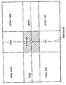
- the measures explained above can be expanded by the area-specific signal evaluation explained in the figure.
- eight area-specific signals are made available during decoding, which does not pose any problems in terms of technical complexity.
- Each of the evaluation fields shown on the left up, up, right up, right, right down, low, left down and left is assigned, for example, a digital signal which is suitable for controlling voice signal generators (not shown).
- the signal generated at the moment during the decoding drives the corresponding speech signal generator which immediately gives the shooter the information "left up” in acoustic form.
Landscapes
- Engineering & Computer Science (AREA)
- Radar, Positioning & Navigation (AREA)
- General Engineering & Computer Science (AREA)
- Electrically Operated Instructional Devices (AREA)
- Closed-Circuit Television Systems (AREA)
Applications Claiming Priority (4)
| Application Number | Priority Date | Filing Date | Title |
|---|---|---|---|
| DE19833329747 DE3329747A1 (de) | 1983-08-17 | 1983-08-17 | Verfahren und vorrichtung zur schiesssimulation |
| DE3329747 | 1983-08-17 | ||
| DE3404203 | 1984-02-07 | ||
| DE19843404203 DE3404203A1 (de) | 1983-08-17 | 1984-02-07 | Verfahren und vorrichtung zur schiesssimulation fuer die schiessausbildung |
Publications (2)
| Publication Number | Publication Date |
|---|---|
| EP0155985A2 true EP0155985A2 (fr) | 1985-10-02 |
| EP0155985A3 EP0155985A3 (fr) | 1988-07-27 |
Family
ID=25813271
Family Applications (1)
| Application Number | Title | Priority Date | Filing Date |
|---|---|---|---|
| EP84109405A Withdrawn EP0155985A3 (fr) | 1983-08-17 | 1984-08-08 | Procédé et dispositif pour la simulation de tir |
Country Status (2)
| Country | Link |
|---|---|
| EP (1) | EP0155985A3 (fr) |
| DE (1) | DE3404203A1 (fr) |
Cited By (2)
| Publication number | Priority date | Publication date | Assignee | Title |
|---|---|---|---|---|
| EP1643206A1 (fr) * | 2004-10-02 | 2006-04-05 | Saab Ab | Système et procédé de simulation et programme informatique |
| EP1870661A1 (fr) * | 2006-06-19 | 2007-12-26 | Saab Ab | Système et procédé de simulation pour déterminer le relèvement compas de moyens de pointage d'un dispositif virtuel de tir pour projectile ou missile |
Citations (8)
| Publication number | Priority date | Publication date | Assignee | Title |
|---|---|---|---|---|
| DE2936643A1 (de) * | 1978-09-13 | 1980-04-24 | Solartron Electronic Group | Verfahren und anordnung fuer die abschaetzung der richtgenauigkeit einer waffe |
| US4240212A (en) * | 1979-06-21 | 1980-12-23 | The United States Of America As Represented By The Secretary Of The Navy | Thermal signature targets |
| US4302191A (en) * | 1979-03-28 | 1981-11-24 | Weibull John L | Aiming and gunnery training apparatus |
| DE3023516A1 (de) * | 1980-06-24 | 1982-01-14 | Wegmann & Co, 3500 Kassel | Einrichtung zur ueberwachung eines kampffahrzeuges, insbesondere eines kampfpanzers |
| FR2500148A1 (fr) * | 1981-02-17 | 1982-08-20 | Thomson Csf | Simulateur d'entrainement au tir au canon anti-aerien sur cibles reelles |
| DE3114000A1 (de) * | 1981-04-07 | 1982-10-28 | Precitronic Gesellschaft für Feinmechanik und Electronic mbH, 2000 Hamburg | Schiesssimulations- und -uebungsverfahren fuer ballistische munition und bewegliche ziele |
| DE3122384A1 (de) * | 1981-06-05 | 1982-12-23 | Wegmann & Co, 3500 Kassel | Geraet mit mehreren ausbildungsplaetzen zur ausbildung von richtschuetzen und/oder kommandanten von kampffahrzeugen |
| DE3222970A1 (de) * | 1982-06-19 | 1983-12-22 | Wegmann & Co GmbH, 3500 Kassel | Einrichtung zur ueberwachung eines kampffahrzeuges, insbesondere eines kampfpanzers |
Family Cites Families (2)
| Publication number | Priority date | Publication date | Assignee | Title |
|---|---|---|---|---|
| DE3010196A1 (de) * | 1980-03-17 | 1981-09-24 | Rudolf 8046 Garching Warmt | Anlage zum simulierten schiessen |
| DE3329747A1 (de) * | 1983-08-17 | 1985-03-07 | Krauss-Maffei AG, 8000 München | Verfahren und vorrichtung zur schiesssimulation |
-
1984
- 1984-02-07 DE DE19843404203 patent/DE3404203A1/de not_active Ceased
- 1984-08-08 EP EP84109405A patent/EP0155985A3/fr not_active Withdrawn
Patent Citations (8)
| Publication number | Priority date | Publication date | Assignee | Title |
|---|---|---|---|---|
| DE2936643A1 (de) * | 1978-09-13 | 1980-04-24 | Solartron Electronic Group | Verfahren und anordnung fuer die abschaetzung der richtgenauigkeit einer waffe |
| US4302191A (en) * | 1979-03-28 | 1981-11-24 | Weibull John L | Aiming and gunnery training apparatus |
| US4240212A (en) * | 1979-06-21 | 1980-12-23 | The United States Of America As Represented By The Secretary Of The Navy | Thermal signature targets |
| DE3023516A1 (de) * | 1980-06-24 | 1982-01-14 | Wegmann & Co, 3500 Kassel | Einrichtung zur ueberwachung eines kampffahrzeuges, insbesondere eines kampfpanzers |
| FR2500148A1 (fr) * | 1981-02-17 | 1982-08-20 | Thomson Csf | Simulateur d'entrainement au tir au canon anti-aerien sur cibles reelles |
| DE3114000A1 (de) * | 1981-04-07 | 1982-10-28 | Precitronic Gesellschaft für Feinmechanik und Electronic mbH, 2000 Hamburg | Schiesssimulations- und -uebungsverfahren fuer ballistische munition und bewegliche ziele |
| DE3122384A1 (de) * | 1981-06-05 | 1982-12-23 | Wegmann & Co, 3500 Kassel | Geraet mit mehreren ausbildungsplaetzen zur ausbildung von richtschuetzen und/oder kommandanten von kampffahrzeugen |
| DE3222970A1 (de) * | 1982-06-19 | 1983-12-22 | Wegmann & Co GmbH, 3500 Kassel | Einrichtung zur ueberwachung eines kampffahrzeuges, insbesondere eines kampfpanzers |
Cited By (3)
| Publication number | Priority date | Publication date | Assignee | Title |
|---|---|---|---|---|
| EP1643206A1 (fr) * | 2004-10-02 | 2006-04-05 | Saab Ab | Système et procédé de simulation et programme informatique |
| EP1870661A1 (fr) * | 2006-06-19 | 2007-12-26 | Saab Ab | Système et procédé de simulation pour déterminer le relèvement compas de moyens de pointage d'un dispositif virtuel de tir pour projectile ou missile |
| US8944821B2 (en) | 2006-06-19 | 2015-02-03 | Saab Ab | Simulation system and method for determining the compass bearing of directing means of a virtual projectile/missile firing device |
Also Published As
| Publication number | Publication date |
|---|---|
| EP0155985A3 (fr) | 1988-07-27 |
| DE3404203A1 (de) | 1985-08-08 |
Similar Documents
| Publication | Publication Date | Title |
|---|---|---|
| DE69812912T2 (de) | Flugkörperschiesssimulator mit eintauchen des schützen in einen virtuellen raum | |
| EP0156944B1 (fr) | Dispositif de surveillance pour véhicules de combat, notamment chars de combat | |
| DE3523459A1 (de) | Vorrichtung zum trainieren mit waffen | |
| DE3122384A1 (de) | Geraet mit mehreren ausbildungsplaetzen zur ausbildung von richtschuetzen und/oder kommandanten von kampffahrzeugen | |
| EP0623799A1 (fr) | Système vidéo interactif | |
| DE2905422A1 (de) | Einrichtung zur schussimulation mit trefferanzeige | |
| DE3702288A1 (de) | Schiessuebungsanlage | |
| DE2812201C2 (de) | Vorrichtung zur Ausbildung von Richtschützen für Panzerfahrzeuge | |
| EP0155985A2 (fr) | Procédé et dispositif pour la simulation de tir | |
| DE2658501A1 (de) | Verfahren zur simulation eines beweglichen zieles | |
| EP0097231A2 (fr) | Dispositif de surveillance d'un véhicule de combat en particulier un véhicule blindé | |
| DE1951622C3 (de) | Anordnung zur simulierten Darstellung von Schußbahnen | |
| DE3405017C2 (de) | Einrichtung zur Überwachung von Kampffahrzeugen, insbesondere von Kampfpanzern, beim Übungsschießen mit simulierten Schüssen | |
| EP1166029B2 (fr) | Procede pour simulation sur un champ de bataille | |
| DE3329747C2 (fr) | ||
| EP0154809A1 (fr) | Procédé de simulation de combat | |
| DE2332094C2 (de) | Verfahren und Einrichtung zur Schiessausbildung von Schützen | |
| EP0090323A1 (fr) | Dispositif d'entraînement pour l'instruction de tir de missiles guidés, en particulier de missiles sol-sol | |
| EP0504690A1 (fr) | Simulateur d'effet d'arme assisté par laser | |
| DE1678620A1 (de) | Simulator zum UEbungsschiessen mit automatisch fernlenkbaren Geschossen | |
| WO2022063909A1 (fr) | Système d'entraînement au combat | |
| DE19617060C2 (de) | Verfahren und Einrichtung zur Simulation der Wirkung von Steilfeuerwaffen auf Gefechtseinheiten | |
| DE3405015C2 (fr) | ||
| DE2148157B2 (de) | Empfangs- und Wiedergabesystem zur Trefferfeststellung und -auswertung für Uchtschußsimulationseinrichtungen mittels Laserstrahlen | |
| EP0222110A2 (fr) | Dispositif complémentaire de simulateurs pour exercice de tir et manoeuvre |
Legal Events
| Date | Code | Title | Description |
|---|---|---|---|
| PUAI | Public reference made under article 153(3) epc to a published international application that has entered the european phase |
Free format text: ORIGINAL CODE: 0009012 |
|
| AK | Designated contracting states |
Designated state(s): AT BE CH FR GB IT LI NL SE |
|
| PUAL | Search report despatched |
Free format text: ORIGINAL CODE: 0009013 |
|
| AK | Designated contracting states |
Kind code of ref document: A3 Designated state(s): AT BE CH FR GB IT LI NL SE |
|
| 17P | Request for examination filed |
Effective date: 19881027 |
|
| 17Q | First examination report despatched |
Effective date: 19900327 |
|
| STAA | Information on the status of an ep patent application or granted ep patent |
Free format text: STATUS: THE APPLICATION HAS BEEN WITHDRAWN |
|
| 18W | Application withdrawn |
Withdrawal date: 19900428 |
|
| R18W | Application withdrawn (corrected) |
Effective date: 19900428 |
|
| RIN1 | Information on inventor provided before grant (corrected) |
Inventor name: FRIE, ULRICH Inventor name: FRANCKE, ERWIN Inventor name: POESCHEL, JUERGEN, DIPL.-ING. |