EP0155693A2 - Procédé et appareil pour le traitement de liquides alimentaires, plus spécialement du mout de vin rouge - Google Patents
Procédé et appareil pour le traitement de liquides alimentaires, plus spécialement du mout de vin rouge Download PDFInfo
- Publication number
- EP0155693A2 EP0155693A2 EP85103354A EP85103354A EP0155693A2 EP 0155693 A2 EP0155693 A2 EP 0155693A2 EP 85103354 A EP85103354 A EP 85103354A EP 85103354 A EP85103354 A EP 85103354A EP 0155693 A2 EP0155693 A2 EP 0155693A2
- Authority
- EP
- European Patent Office
- Prior art keywords
- sieve
- mash
- tank
- pomace
- fermentation
- Prior art date
- Legal status (The legal status is an assumption and is not a legal conclusion. Google has not performed a legal analysis and makes no representation as to the accuracy of the status listed.)
- Granted
Links
Images
Classifications
-
- C—CHEMISTRY; METALLURGY
- C12—BIOCHEMISTRY; BEER; SPIRITS; WINE; VINEGAR; MICROBIOLOGY; ENZYMOLOGY; MUTATION OR GENETIC ENGINEERING
- C12G—WINE; PREPARATION THEREOF; ALCOHOLIC BEVERAGES; PREPARATION OF ALCOHOLIC BEVERAGES NOT PROVIDED FOR IN SUBCLASSES C12C OR C12H
- C12G1/00—Preparation of wine or sparkling wine
- C12G1/02—Preparation of must from grapes; Must treatment and fermentation
-
- B—PERFORMING OPERATIONS; TRANSPORTING
- B01—PHYSICAL OR CHEMICAL PROCESSES OR APPARATUS IN GENERAL
- B01F—MIXING, e.g. DISSOLVING, EMULSIFYING OR DISPERSING
- B01F25/00—Flow mixers; Mixers for falling materials, e.g. solid particles
- B01F25/50—Circulation mixers, e.g. wherein at least part of the mixture is discharged from and reintroduced into a receptacle
-
- B—PERFORMING OPERATIONS; TRANSPORTING
- B01—PHYSICAL OR CHEMICAL PROCESSES OR APPARATUS IN GENERAL
- B01F—MIXING, e.g. DISSOLVING, EMULSIFYING OR DISPERSING
- B01F27/00—Mixers with rotary stirring devices in fixed receptacles; Kneaders
- B01F27/60—Mixers with rotary stirring devices in fixed receptacles; Kneaders with stirrers rotating about a horizontal or inclined axis
- B01F27/70—Mixers with rotary stirring devices in fixed receptacles; Kneaders with stirrers rotating about a horizontal or inclined axis with paddles, blades or arms
-
- B—PERFORMING OPERATIONS; TRANSPORTING
- B01—PHYSICAL OR CHEMICAL PROCESSES OR APPARATUS IN GENERAL
- B01F—MIXING, e.g. DISSOLVING, EMULSIFYING OR DISPERSING
- B01F27/00—Mixers with rotary stirring devices in fixed receptacles; Kneaders
- B01F27/05—Stirrers
- B01F27/07—Stirrers characterised by their mounting on the shaft
- B01F27/072—Stirrers characterised by their mounting on the shaft characterised by the disposition of the stirrers with respect to the rotating axis
- B01F27/0721—Stirrers characterised by their mounting on the shaft characterised by the disposition of the stirrers with respect to the rotating axis parallel with respect to the rotating axis
-
- B—PERFORMING OPERATIONS; TRANSPORTING
- B01—PHYSICAL OR CHEMICAL PROCESSES OR APPARATUS IN GENERAL
- B01F—MIXING, e.g. DISSOLVING, EMULSIFYING OR DISPERSING
- B01F27/00—Mixers with rotary stirring devices in fixed receptacles; Kneaders
- B01F27/05—Stirrers
- B01F27/11—Stirrers characterised by the configuration of the stirrers
- B01F27/112—Stirrers characterised by the configuration of the stirrers with arms, paddles, vanes or blades
- B01F27/1125—Stirrers characterised by the configuration of the stirrers with arms, paddles, vanes or blades with vanes or blades extending parallel or oblique to the stirrer axis
-
- C—CHEMISTRY; METALLURGY
- C12—BIOCHEMISTRY; BEER; SPIRITS; WINE; VINEGAR; MICROBIOLOGY; ENZYMOLOGY; MUTATION OR GENETIC ENGINEERING
- C12G—WINE; PREPARATION THEREOF; ALCOHOLIC BEVERAGES; PREPARATION OF ALCOHOLIC BEVERAGES NOT PROVIDED FOR IN SUBCLASSES C12C OR C12H
- C12G2200/00—Special features
- C12G2200/25—Preparation of wine or sparkling wine in vessels with movable equipment for mixing the content
Definitions
- the invention relates to a method for treating liquid foodstuffs, in particular red wine mash, in which the mash is filled into the tank from below until the mirror is arranged above an element in the upper part of the tank which fills the cross-sectional area and retains pomace components of the mash Siebes stands and the mash is left in this state for a predetermined period of fermentation.
- the invention further relates to a device for the treatment of liquid foods, in particular red wine mash with a tank, on the underside of which there is a filler neck for pumping in the mash and which is provided with a sieve spanning the clear cross section of the tank perpendicular to the vertical axis, the upper one Area of the tank is located just below the level of the pumped-in mash.
- a method and a device for making red wine are known, in which a tank-shirt-like, bulbous downward-hanging sieve is arranged in a standing tank at about 3/4 of the tank height.
- the red wine mash with pomace components is introduced into the space below the sieve until a level is reached at which the level of the grape juice is above the Siebes stands.
- the pomace components rise and arch the sieve upwards. If the mash is pumped out below the sieve, the direction of curvature of the sieve is reversed again, the pomace cake breaks and the solid components fall to the bottom of the now empty tank.
- a device for fermenting red wine mash in which a truncated cone-shaped fermentation stand is used as a mash container.
- a sieve filling the cross section is provided in the upper area, which holds the pomace components rising upwards below the liquid level.
- a stirrer which can be rotated about a horizontal axis and which is provided with spoon-like stirrer arms and is intended to stir the mash.
- FR-OS 2 440 991 describes a method and a device for fermenting red wine mash, the one in the upper part of a standing circular cylindrical tank Cross-section filling sieve is provided, under which the mash can be pumped in by means of a pipe opening laterally into the tank.
- the top of the tank is hermetically sealed and the mash is only pumped up to a level just below the sieve.
- a line provided with a pump leads into the area of the dome of the tank and consequently juice can be sucked off at the bottom of the tank and pumped in again above the sieve.
- the sieve therefore does not act directly on the fermentation process and there are also no mechanical treatment agents for the red wine mash.
- FR-OS 2 168 214 also describes a large-scale plant for fermenting red wine mash, in which a total of seven tanks are connected in a cascade manner.
- a sieve in the upper area and the incoming red wine mash is pumped into the tanks below the sieve until the level of the liquid is above the sieves.
- Grape juice can now be taken from the area above the sieve and poured into the area below the sieve of the neighboring tank.
- sucking out juice below the sieve and pumping it over a fountain-like tube into the area above the sieve There is also the possibility of also sucking out juice below the sieve and pumping it over a fountain-like tube into the area above the sieve.
- the invention is therefore based on the object of developing a method and a device of the type mentioned in such a way that, with optimally gentle treatment of the red wine mash, high wine quality in the form of a particularly beautiful color of the red wine can be achieved.
- this object is achieved according to the invention in that a sieve which is rotatable about a horizontal axis is used as a sieve and the mash is stirred after a predetermined time by rotating this sieve.
- the object is achieved in that the sieve can be rotated about a horizontal axis.
- the method and the device according to the invention thus have the advantage that, while maintaining the advantage known from some of the publications mentioned at the outset, that the dyes are "automatically” washed out of the pomace component by the fermentation of the mash and the rising bubbles when the mash is mousseed which accumulate below the sieve and are transferred into the pure grape juice located above the sieve, the dye leaching is additionally increased considerably by mechanically stirring the mash, this stirring being very simple, on the one hand, because no additional devices in the tank are required are also very gentle because the sieve that fills the entire cross section Mash turns gently and neither creates turbid substances nor bitter taste components are released from the kernels.
- the grape juice is sucked off above the sieve and pumped back into the tank below the pomace that has risen to the underside of the sieve.
- the mash can be heated to accelerate the start of fermentation by means of heat exchangers contained in the sieve and / or be cooled during the fermentation, as is known per se.
- This measure has the advantage that the mash temperature is kept largely constant during the entire fermentation process, in that the mash, which is initially too cold, is brought to a fermentation start temperature and the self-developing fermentation heat is then dissipated via the heat exchanger.
- the sieve used in the method or device described above can be flat.
- This measure has the advantage that the pomace components of the mash, which due to their lower weight rise upwards and collect below the sieve, are evenly distributed there, which would be less the case with a funnel-like or conical sieve, because the pomace components there laterally would slide up to the highest point of the sieve.
- the tank can essentially consist of an upright circular cylindrical part and the sieve can be circular.
- This measure has the advantage that the device can be used in conventional tanks, so that new designs of the tank itself are not necessary. Also lets. in such cases the device can easily be retrofitted to existing tanks.
- an outlet connection is arranged above the sieve and below the mirror in the wall of the tank, which is connected via a line and a pump to an inlet which opens into the mash below the sieve.
- the inlet is a radial line of the sieve which merges into an axial line of a downward-pointing axial arm, which is provided at its lower end with a spray head with upward-pointing nozzles.
- This measure has the advantage that the grape juice pumped in below the pomace components is immediately pumped in the direction of the pomace, so that unnecessary turbulence in the grape juice portion below the pomace is avoided.
- the features mentioned are advantageous if the screen is held on the inside of the tank in height-adjustable brackets. Then namely the type of pumping regardless of the respective height of the screen, because the spray head is moved with the screen in the axial direction.
- the height adjustability of the screen has the essential advantage that the device according to the invention can be adapted to different filling conditions of the tank. This is particularly important because high-quality wines are generally only delivered in very small quantities and therefore sometimes do not even fill up a single tank in a winery, as such cellar tanks have to be available for different wine qualities and therefore with regard to the large ones delivered quantities of usual wines are also designed to be as large as possible in order to be able to work economically.
- the sieve can be provided with a heat exchanger in a manner known per se, in order to be able to carry out the temperature control of the mash before fermentation and during fermentation, as already explained above.
- the tank is preferably made of steel or stainless steel, but, provided the static conditions permit, it can also consist of plastic, in particular glass-fiber reinforced plastic, for cost reasons. This choice within the material also applies to the components of the tank, i.e. the agitators, closures, sieves and the like.
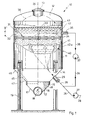
- FIG. 1 designates a standing tank as it is usually used for the treatment of red wine mash according to its outer shape.
- the tank 10 consists essentially of a cylindrical part 11, which is closed at the top with a dome 12, in which there is an opening 13, which can be designed, for example, as a manhole.
- a conical part 14 which in turn merges into a cylindrical section 15 on its underside.
- the cylindrical section 15 merges into a tapered section 16 on its underside, which is created by the cylindrical section 15 being cut laterally by two flat inclined surfaces 17.
- a discharge screw 18 is arranged between the inclined surfaces 17.
- the tank 10 and possibly provided components such as agitators, sieves, closures and the like can be made of steel, stainless steel or plastic, in particular glass fiber reinforced plastic.
- the tank 10 is supported by a total of several legs 19 which act on the tank 10 in the transition area from the cylindrical part 11 to the conical part 14.
- the vertical axis of the tank 10 is designated by 24.
- a filler neck 25 can be seen, to which a line 26 only indicated schematically leads.
- a pump 27 is connected to line 26 and can pump mash from a line 28, which leads, for example, to a delivering vehicle, via line 26 and the filler neck 25 into the tank 10 from below.
- a horizontally arranged, flat sieve 31 can be seen, which can consist, for example, of a frame body and several sieve inserts 32 used.
- the sieve 31 can be arranged rotatably about a horizontally extending axis 33, which is arranged perpendicular to the plane of the drawing in FIG. 1, as indicated by the direction of rotation 38.
- an outlet connection 35 can be provided in the wall 34 of the tank 10, from which a line 36, which is only indicated schematically, leads to a further pump 37 and from there further as a branch line to the line 26, which opens into the filler neck 25. It is understood that the pumps 27 and 37 can also be one and the same pump and the pipes are connected accordingly by suitable valve arrangements.
- the mash pumped into the tank 10 from below via the filler neck 25 is indicated by 40.
- the mash 40 contains solid components, so-called pomace 41, which due to their lower weight rise upwards and therefore collect underneath the sieve 31, which spans the entire internal cross-section of the tank 10. According to the invention, more mash 40 is pumped into the tank 10 than corresponds to the volume below the sieve 31. Because of this, grape juice 42 rises through the sieve 31 until a mirror 43 is reached which is at a height d above the sieve 31.
- the height d of the mirror 43 is 15 cm, for example. Care must be taken to ensure that sufficient fermentation space remains above the mirror 43 and below the dome 12 so that the mash 40 still has sufficient space during the fermentation.
- the mash 40 is first pumped into the tank 10 from below via the pump 27 until the grape juice above the sieve 31 has reached the mirror 43.
- the mash can now be left to its own devices, as will be explained further below in relation to FIG. 2.
- a closed circuit is produced by means of the line 36 and the pump 37, in which grape juice 42 is sucked off above the sieve 31 and pumped back into the tank 10 from below via the filler neck 25 or another separate neck. This then results in the closed circuit shown by arrows in FIG. 1, from which it can easily be seen that the grape juice 42 flushing through the pomace 41 can easily wash out the red dyes from the grape skins which are part of the pomace 41.
- the sieve 31 can be set in rotation about the axis 33 at the end of the method according to the invention, for example by means of a drive (not shown in FIG. 1), so that there is a movement in the direction 38 according to FIG. 1.
- a further stirring step in the method according to the invention can be used to further wash out the dyes from the fragments of the pomace cake.
- the grape juice 42 can then be drained out of the tank 10 in a manner known per se.
- a device shown in FIG. 1, left half, below can be used, in which a funnel-shaped sieve 45 is arranged at a distance from the wall 34 in the region of the parts 11, 14, 15.
- a juice chamber 46 is thus defined below the sieve 45, from which a nozzle 47 leads to the outside.
- the grape juice 42 can be drained through the nozzle 47, while the sieve 45 retains the pomace 41.
- cylindrical part 15 can also be provided with a flat circular sieve 48, as shown in the lower right half of FIG. 1, so that the juice chamber is formed by the tapering section 16 and the grape juice 42 via the discharge screw 18 itself can be drained.
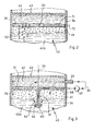
- FIG. 2 shows an embodiment of the invention in which there is no mechanical action on the mash 40 in the form of a closed grape juice cycle.
- the pomace 41 collects below the sieve 31 in the manner described, which is only shown schematically in FIG. 2, the mash 40 begins to ferment after a certain time. Both in the pomace 41 and in the grape juice portion 42a located below the pomace, fermentation bubbles 50 form which rise upwards and cross the pomace 41. The red dyes are washed out of the grape skins of the pomace 41 by the fermentation vesicles 50 and the entrained liquid particles and are conveyed upwards into the pure grape juice 42 located above the sieve 31 with the fermentation vesicles 50.
- a variant of the sieve 31 is shown, in which it is provided with a heat exchanger 71 which leads to the outside via lines 72 and is connected there to a corresponding device which is not the subject of the present invention .
- the heat exchanger 71 With the help of the heat exchanger 71, the filled mash, which is relatively cool, can first be brought to the so-called fermentation start temperature. When the fermentation then takes place, the resulting fermentation heat can then be removed by introducing a coolant into the line 72, so that the mash 40 is not overheated.
- Fig. 3 shows a further variant, in which a closed circuit of the grape juice is again provided. 1, however, the grape juice is not conveyed back into the tank below the sieve 31, but rather into a radial line 60 of the sieve 31 itself, which is located in a part of the sieve 31, which is shown in FIG. 3 as broken section is shown in section.
- the sieve 31 merges into an arm 61 projecting axially downward, in which there is an axial line 62 which is connected to the radial line 60.
- the arm 61 opens at the bottom into a spray head 63 which is provided with upwardly directed nozzles 64 which are connected to the axial line 62.
- a closed cycle of the grape juice 42 is again established.
- This is sucked off by means of the pump 37 via the outlet connection 35 above the sieve 31 and pumped into the radial line 60 via the line 36, reaches the nozzles 64 via the axial line 61 and is sprayed with the latter against the pomace 41 or rinsed.
- the grape juice 42 thus flows through the pomace 41 and the sieve 31 in a targeted direction and thus, enriched with colorants, reaches the area above the sieve 31 again.
- FIG. 3 shows yet another variant of the device according to the invention, because one can see in the left part of FIG. 3 a height-adjustable holder 75 with which the sieve 31 in the tank 10 is adjustable in the direction of the vertical axis 24 in order to be able to adapt to different filling states of the tank.
Landscapes
- Chemical & Material Sciences (AREA)
- Chemical Kinetics & Catalysis (AREA)
- Organic Chemistry (AREA)
- General Health & Medical Sciences (AREA)
- Engineering & Computer Science (AREA)
- Biochemistry (AREA)
- Bioinformatics & Cheminformatics (AREA)
- General Engineering & Computer Science (AREA)
- Life Sciences & Earth Sciences (AREA)
- Genetics & Genomics (AREA)
- Health & Medical Sciences (AREA)
- Wood Science & Technology (AREA)
- Zoology (AREA)
- Distillation Of Fermentation Liquor, Processing Of Alcohols, Vinegar And Beer (AREA)
- Preparation Of Fruits And Vegetables (AREA)
- Dairy Products (AREA)
Priority Applications (1)
| Application Number | Priority Date | Filing Date | Title |
|---|---|---|---|
| AT85103354T ATE45891T1 (de) | 1984-03-22 | 1985-03-22 | Verfahren und vorrichtung zum behandeln von fluessigen nahrungsmitteln, insbesondere rotwein- maische. |
Applications Claiming Priority (2)
| Application Number | Priority Date | Filing Date | Title |
|---|---|---|---|
| DE3410457 | 1984-03-22 | ||
| DE3410457 | 1984-03-22 |
Publications (3)
| Publication Number | Publication Date |
|---|---|
| EP0155693A2 true EP0155693A2 (fr) | 1985-09-25 |
| EP0155693A3 EP0155693A3 (en) | 1985-11-27 |
| EP0155693B1 EP0155693B1 (fr) | 1989-08-30 |
Family
ID=6231229
Family Applications (1)
| Application Number | Title | Priority Date | Filing Date |
|---|---|---|---|
| EP85103354A Expired EP0155693B1 (fr) | 1984-03-22 | 1985-03-22 | Procédé et appareil pour le traitement de liquides alimentaires, plus spécialement du mout de vin rouge |
Country Status (5)
| Country | Link |
|---|---|
| US (1) | US4665807A (fr) |
| EP (1) | EP0155693B1 (fr) |
| AT (1) | ATE45891T1 (fr) |
| DE (1) | DE3572599D1 (fr) |
| ZA (1) | ZA852170B (fr) |
Cited By (1)
| Publication number | Priority date | Publication date | Assignee | Title |
|---|---|---|---|---|
| CN109092117A (zh) * | 2018-10-25 | 2018-12-28 | 楼阳英 | 化妆品加工设备 |
Families Citing this family (17)
| Publication number | Priority date | Publication date | Assignee | Title |
|---|---|---|---|---|
| US4754698A (en) * | 1986-12-01 | 1988-07-05 | Naish Ralph P | Home brewing apparatus |
| IT1269436B (it) * | 1994-01-17 | 1997-04-01 | Nuova Maip Macchine Agric | Procedimento per l'ottenimento di mosto da grappoli di uva comprendente almeno una fase di centrifugazione del grappolo stesso |
| US6837147B2 (en) * | 2002-06-24 | 2005-01-04 | Rule Steel, an Idaho Corporation | No-solids-build-up tank |
| US20040226451A1 (en) * | 2003-05-15 | 2004-11-18 | Christopher Diaz | Wine tank and method of use |
| US7870891B2 (en) | 2004-05-29 | 2011-01-18 | Kilr-Chilr, Llc | Systems, devices and methods for regulating temperatures of tanks, containers and contents therein |
| US20050281911A1 (en) * | 2004-06-18 | 2005-12-22 | Instituto Nacional De Tecnologia Agropecuaria | Self macerating-fermenting vessel |
| US20080175951A1 (en) * | 2007-01-23 | 2008-07-24 | Rule David D | Methods, apparatuses and systems of fermentation |
| DE102009013579A1 (de) * | 2009-03-19 | 2010-09-23 | Gea Brewery Systems Gmbh | Brauereianlage zur Herstellung und Abfüllung von Bier |
| US9637307B2 (en) * | 2013-01-22 | 2017-05-02 | Spokane Industries | Sliding-locking below liquid manway door |
| US10253284B2 (en) * | 2013-12-03 | 2019-04-09 | John R. Blichmann | Modular keg and conical fermentor |
| DE102013020376A1 (de) | 2013-12-05 | 2015-06-11 | Günter Landgraf | Bindemittel für die Herstellung von Siebdruckpasten |
| EP3212755B1 (fr) * | 2014-10-31 | 2019-12-18 | U.G.C. Sas di Ghidi Pietro & C. | Cuve pour la fermentation du vin |
| WO2016126249A1 (fr) | 2015-02-04 | 2016-08-11 | Rule David D | Systèmes de transport d'énergie et procédés de transport d'énergie |
| WO2018058025A1 (fr) * | 2016-09-26 | 2018-03-29 | Andritz Separation Inc. | Système et procédé d'extraction de sédiments à partir d'un récipient à fond conique doté d'un conduit en t de restriction et d'une centrifugeuse |
| CN109554257B (zh) * | 2017-09-25 | 2022-12-13 | 郑州兰茜生物工程有限公司 | 一种新型多功能葡萄酒发酵装置 |
| CN107788120A (zh) * | 2017-11-10 | 2018-03-13 | 安徽金思源生物科技有限公司 | 一种利用微生物食品发酵筛选装置 |
| CN113083128B (zh) * | 2021-04-26 | 2022-07-22 | 江西京九电源(九江)有限公司 | 一种蓄电池铅膏合膏用装置 |
Citations (4)
| Publication number | Priority date | Publication date | Assignee | Title |
|---|---|---|---|---|
| GB149136A (en) * | 1919-08-22 | 1920-08-12 | Robert Hendry Morton | Improvements in apparatus for mixing or beating liquids or semi-liquid substances |
| FR831877A (fr) * | 1937-04-19 | 1938-09-15 | Laiteries De La Vallee De La V | Dispositif batteur, malaxeur et mélangeur mécanique |
| FR2402470A1 (fr) * | 1977-09-08 | 1979-04-06 | Giusti International Ltd | Recipient de traitement |
| FR2512056A1 (fr) * | 1981-09-01 | 1983-03-04 | Gimar Tecno Spa | Recipient pour vinification |
Family Cites Families (8)
| Publication number | Priority date | Publication date | Assignee | Title |
|---|---|---|---|---|
| DE258102C (fr) * | ||||
| DE628392C (de) * | 1932-12-29 | 1936-04-03 | Daubron Ets | Verfahren und Einrichtung zur Rotweinbereitung |
| AT231930B (de) * | 1961-11-08 | 1964-02-25 | Karl Holler | Vorrichtung zum Vergären von Rotweinmaische |
| DE1517469A1 (de) * | 1965-01-28 | 1970-09-17 | Malto S A | Wasseraufbereitungsanlage Bauart Malto-Malto Spezialverfahren |
| FR2168214A1 (en) * | 1972-01-20 | 1973-08-31 | Bellot Roger | Wine fermentation process - accelerated by mixing fresh juice with pre-fermented must |
| US3910173A (en) * | 1974-06-03 | 1975-10-07 | Winery Systems Inc | Wine grape processing apparatus |
| DE2818013A1 (de) * | 1978-04-25 | 1979-11-08 | Schaerf Gmbh W | Verfahren zum vergaeren von rotweinmaische und vorrichtung zum durchfuehren dieses verfahrens |
| IT1103919B (it) * | 1978-11-07 | 1985-10-14 | Pujatti Giampaolo | Tino vinificatore pluri uso particolarmente adatto per vini pregiati |
-
1985
- 1985-03-21 US US06/714,707 patent/US4665807A/en not_active Expired - Fee Related
- 1985-03-22 AT AT85103354T patent/ATE45891T1/de active
- 1985-03-22 ZA ZA852170A patent/ZA852170B/xx unknown
- 1985-03-22 DE DE8585103354T patent/DE3572599D1/de not_active Expired
- 1985-03-22 EP EP85103354A patent/EP0155693B1/fr not_active Expired
Patent Citations (4)
| Publication number | Priority date | Publication date | Assignee | Title |
|---|---|---|---|---|
| GB149136A (en) * | 1919-08-22 | 1920-08-12 | Robert Hendry Morton | Improvements in apparatus for mixing or beating liquids or semi-liquid substances |
| FR831877A (fr) * | 1937-04-19 | 1938-09-15 | Laiteries De La Vallee De La V | Dispositif batteur, malaxeur et mélangeur mécanique |
| FR2402470A1 (fr) * | 1977-09-08 | 1979-04-06 | Giusti International Ltd | Recipient de traitement |
| FR2512056A1 (fr) * | 1981-09-01 | 1983-03-04 | Gimar Tecno Spa | Recipient pour vinification |
Cited By (1)
| Publication number | Priority date | Publication date | Assignee | Title |
|---|---|---|---|---|
| CN109092117A (zh) * | 2018-10-25 | 2018-12-28 | 楼阳英 | 化妆品加工设备 |
Also Published As
| Publication number | Publication date |
|---|---|
| ATE45891T1 (de) | 1989-09-15 |
| EP0155693A3 (en) | 1985-11-27 |
| EP0155693B1 (fr) | 1989-08-30 |
| US4665807A (en) | 1987-05-19 |
| DE3572599D1 (en) | 1989-10-05 |
| ZA852170B (en) | 1985-11-27 |
Similar Documents
| Publication | Publication Date | Title |
|---|---|---|
| EP0155693B1 (fr) | Procédé et appareil pour le traitement de liquides alimentaires, plus spécialement du mout de vin rouge | |
| CH665651A5 (de) | Gaerungsapparat und verfahren zu dessen betrieb. | |
| EP0052298A2 (fr) | Dispositif agitateur pour récipient de fermentation du moût de raisin | |
| DE3617519A1 (de) | Zwei- oder mehrstufiges verfahren zum entfernen von verunreinigungen aus stillen oder kohlensaeurehaltigen fluessigkeiten, insbesondere getraenken, sowie vorrichtung zu dessen durchfuehrung | |
| DE2643211A1 (de) | Verfahren und vorrichtung zum reinigen von abluft | |
| DE3415699C2 (de) | Verfahren und Vorrichtung zum Gären von Rotwein-Maische | |
| DE3902620C2 (fr) | ||
| DE1767805A1 (de) | Verfahren und Vorrichtung zum Waschen von Fasersuspensionen | |
| EP3887495B1 (fr) | Dispositif de brassage | |
| DE2138159C3 (de) | Verfahren und Vorrichtung zum Polieren der Innen- und Außenflächen von Hohlglaskörpern in einem bewegten Polierätzbad, bei dem die Polierflüssigkeit nach erfolgter Einwirkung abfließt | |
| EP0159547B1 (fr) | Récipient vertical pour le traitement de liquides alimentaires contenant des solides | |
| DE3809511C1 (fr) | ||
| CH654560A5 (en) | Method and device for oxygen enrichment of the deep water in stagnant waters | |
| DE3500654A1 (de) | Vorrichtung zur weinbereitung | |
| EP0535169A1 (fr) | Recipient et procede pour l'extraction de mout | |
| DE4136491C2 (de) | Verfahren und Vorrichtung zum Gären von Rotweinmaische | |
| DE2818013A1 (de) | Verfahren zum vergaeren von rotweinmaische und vorrichtung zum durchfuehren dieses verfahrens | |
| DE3415701C1 (de) | Stehender Weinmaische-Tank | |
| DE3200714A1 (de) | Liegender behaelter zur behandlung von weinmaische | |
| DE3927173C1 (fr) | ||
| AT219538B (de) | Vorrichtung zum Vorentsaften von Maische, insbesondere Traubenmaische | |
| DE2141465C3 (de) | Vorrichtung zum Waschen und Kühlen von Hüttenkäse, Quark oder diesem in der Konsistenz ähnlichen Produkten Hinds jun, Horace, Mountain View, Calif. (V-StA.) | |
| AT273017B (de) | Automatische Gärvorrichtung | |
| AT225653B (de) | Läutergefäß bzw. Extraktionsgefäß für Maischetreber und Verfahren zum Würzeabzug aus einem solchen Läutergefäß | |
| DE1767890A1 (de) | Gaervorrichtung |
Legal Events
| Date | Code | Title | Description |
|---|---|---|---|
| PUAI | Public reference made under article 153(3) epc to a published international application that has entered the european phase |
Free format text: ORIGINAL CODE: 0009012 |
|
| PUAL | Search report despatched |
Free format text: ORIGINAL CODE: 0009013 |
|
| AK | Designated contracting states |
Designated state(s): AT BE CH DE FR GB IT LI NL |
|
| RHK1 | Main classification (correction) |
Ipc: B01F 7/10 |
|
| AK | Designated contracting states |
Designated state(s): AT BE CH DE FR GB IT LI NL |
|
| 17P | Request for examination filed |
Effective date: 19851122 |
|
| 17Q | First examination report despatched |
Effective date: 19870320 |
|
| GRAA | (expected) grant |
Free format text: ORIGINAL CODE: 0009210 |
|
| AK | Designated contracting states |
Kind code of ref document: B1 Designated state(s): AT BE CH DE FR GB IT LI NL |
|
| PG25 | Lapsed in a contracting state [announced via postgrant information from national office to epo] |
Ref country code: NL Effective date: 19890830 Ref country code: GB Effective date: 19890830 Ref country code: BE Effective date: 19890830 |
|
| REF | Corresponds to: |
Ref document number: 45891 Country of ref document: AT Date of ref document: 19890915 Kind code of ref document: T |
|
| REF | Corresponds to: |
Ref document number: 3572599 Country of ref document: DE Date of ref document: 19891005 |
|
| ITF | It: translation for a ep patent filed |
Owner name: BUGNION S.P.A. |
|
| ET | Fr: translation filed | ||
| NLV1 | Nl: lapsed or annulled due to failure to fulfill the requirements of art. 29p and 29m of the patents act | ||
| GBV | Gb: ep patent (uk) treated as always having been void in accordance with gb section 77(7)/1977 [no translation filed] | ||
| PG25 | Lapsed in a contracting state [announced via postgrant information from national office to epo] |
Ref country code: AT Effective date: 19900322 |
|
| PG25 | Lapsed in a contracting state [announced via postgrant information from national office to epo] |
Ref country code: LI Effective date: 19900331 Ref country code: CH Effective date: 19900331 |
|
| PLBE | No opposition filed within time limit |
Free format text: ORIGINAL CODE: 0009261 |
|
| STAA | Information on the status of an ep patent application or granted ep patent |
Free format text: STATUS: NO OPPOSITION FILED WITHIN TIME LIMIT |
|
| 26N | No opposition filed | ||
| REG | Reference to a national code |
Ref country code: CH Ref legal event code: PL |
|
| PGFP | Annual fee paid to national office [announced via postgrant information from national office to epo] |
Ref country code: FR Payment date: 19910314 Year of fee payment: 7 |
|
| ITTA | It: last paid annual fee | ||
| PGFP | Annual fee paid to national office [announced via postgrant information from national office to epo] |
Ref country code: DE Payment date: 19910426 Year of fee payment: 7 |
|
| PG25 | Lapsed in a contracting state [announced via postgrant information from national office to epo] |
Ref country code: FR Effective date: 19921130 |
|
| PG25 | Lapsed in a contracting state [announced via postgrant information from national office to epo] |
Ref country code: DE Effective date: 19921201 |
|
| REG | Reference to a national code |
Ref country code: FR Ref legal event code: ST |