EP0146770A2 - Vorsatzobjektiv zur Projektion von stereoskopischen, anamorphotisch komprimierten Bildpaaren auf eine gekrümmte Breitwandfläche - Google Patents
Vorsatzobjektiv zur Projektion von stereoskopischen, anamorphotisch komprimierten Bildpaaren auf eine gekrümmte Breitwandfläche Download PDFInfo
- Publication number
- EP0146770A2 EP0146770A2 EP84113881A EP84113881A EP0146770A2 EP 0146770 A2 EP0146770 A2 EP 0146770A2 EP 84113881 A EP84113881 A EP 84113881A EP 84113881 A EP84113881 A EP 84113881A EP 0146770 A2 EP0146770 A2 EP 0146770A2
- Authority
- EP
- European Patent Office
- Prior art keywords
- lens
- projection
- compressed
- image pairs
- anamorphotically
- Prior art date
- Legal status (The legal status is an assumption and is not a legal conclusion. Google has not performed a legal analysis and makes no representation as to the accuracy of the status listed.)
- Granted
Links
- 230000003287 optical effect Effects 0.000 claims abstract description 14
- 230000005499 meniscus Effects 0.000 claims description 2
- 238000003384 imaging method Methods 0.000 abstract description 2
- 238000005286 illumination Methods 0.000 description 4
- 239000000463 material Substances 0.000 description 4
- 230000000694 effects Effects 0.000 description 3
- 229910052734 helium Inorganic materials 0.000 description 3
- 239000001307 helium Substances 0.000 description 3
- SWQJXJOGLNCZEY-UHFFFAOYSA-N helium atom Chemical compound [He] SWQJXJOGLNCZEY-UHFFFAOYSA-N 0.000 description 3
- 238000000034 method Methods 0.000 description 3
- 230000010287 polarization Effects 0.000 description 3
- 239000010453 quartz Substances 0.000 description 3
- VYPSYNLAJGMNEJ-UHFFFAOYSA-N silicon dioxide Inorganic materials O=[Si]=O VYPSYNLAJGMNEJ-UHFFFAOYSA-N 0.000 description 3
- 230000006837 decompression Effects 0.000 description 2
- 230000003247 decreasing effect Effects 0.000 description 1
- 238000005516 engineering process Methods 0.000 description 1
- 239000011521 glass Substances 0.000 description 1
- 238000004519 manufacturing process Methods 0.000 description 1
- 230000007246 mechanism Effects 0.000 description 1
- 238000012634 optical imaging Methods 0.000 description 1
- 238000001429 visible spectrum Methods 0.000 description 1
- 229910052724 xenon Inorganic materials 0.000 description 1
- FHNFHKCVQCLJFQ-UHFFFAOYSA-N xenon atom Chemical compound [Xe] FHNFHKCVQCLJFQ-UHFFFAOYSA-N 0.000 description 1
Images
Classifications
-
- G—PHYSICS
- G03—PHOTOGRAPHY; CINEMATOGRAPHY; ANALOGOUS TECHNIQUES USING WAVES OTHER THAN OPTICAL WAVES; ELECTROGRAPHY; HOLOGRAPHY
- G03B—APPARATUS OR ARRANGEMENTS FOR TAKING PHOTOGRAPHS OR FOR PROJECTING OR VIEWING THEM; APPARATUS OR ARRANGEMENTS EMPLOYING ANALOGOUS TECHNIQUES USING WAVES OTHER THAN OPTICAL WAVES; ACCESSORIES THEREFOR
- G03B35/00—Stereoscopic photography
-
- G—PHYSICS
- G03—PHOTOGRAPHY; CINEMATOGRAPHY; ANALOGOUS TECHNIQUES USING WAVES OTHER THAN OPTICAL WAVES; ELECTROGRAPHY; HOLOGRAPHY
- G03B—APPARATUS OR ARRANGEMENTS FOR TAKING PHOTOGRAPHS OR FOR PROJECTING OR VIEWING THEM; APPARATUS OR ARRANGEMENTS EMPLOYING ANALOGOUS TECHNIQUES USING WAVES OTHER THAN OPTICAL WAVES; ACCESSORIES THEREFOR
- G03B37/00—Panoramic or wide-screen photography; Photographing extended surfaces, e.g. for surveying; Photographing internal surfaces, e.g. of pipe
Definitions
- the invention is in the field of optical imaging and relates to an attachment lens for projecting stereoscopic, anamorphically compressed image pairs onto a curved wide wall surface.
- FR-A-398'746 initiated a procedure with Vorrich tion known to obtain a plastic image effect.
- Vorrich tion known to obtain a plastic image effect.
- stereoscopic image pairs recorded on a film were projected as exactly as possible overlapped by two inclined projection objectives.
- the proposed projector works with two separate light sources. In a simplified version, it is proposed to distribute the light from one source evenly between the two lenses.
- the invention has the task of creating an attachment lens. which is suitable for the projection of stereoscopic image pairs on a spherical projection surface.
- this device can be used to convert a normal commercial cinema projector into a projection device for stereoscopic, anamorphic compressed image pairs can be upgraded to extremely large, spherically curved wide wall surfaces.
- the problem is to supply the energy emitted by the light sources in the visible spectrum as quantitatively as possible and finally to anamorphically equalize the irradiated image pairs and to project them onto the oversized screen with sufficient light intensity, i.e. to fully illuminate this screen.
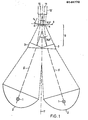
- FIG. 1 shows a top view of the illuminating device for illuminating stereoscopic image pairs.
- This device consists of two xenon high-pressure arc lamps from e.g. four kilowatt power each.
- Each of these arc lamps is surrounded by an ellipsoidal mirror 2 in such a way that the light rays, as indicated by dashed lines, reach the first deflecting prism 3 in the direction of the optical axis 5.
- Each of the ellipsoid mirrors has focal lengths of essentially 60 mm and 540 mm.
- the diameter of the mirror at its edge is approximately 280 mm.
- the figure also shows that the arc lamps 1 and mirrors 2 are arranged symmetrically to a plane of symmetry 7.
- the angle between the plane of symmetry 7 and the optical axes 5 is 18.5 in the present exemplary embodiment.
- the first deflection prism can be made of quartz with a wedge angle of 19.56 or of the material "ZK N7" with a wedge angle of 17.5 o .
- a first deflection prism 3 is provided for each of the optical axes.
- the optical axis direction is thereby deflected to an angle of 9.3 ° to the plane of symmetry 7, which is dashed in the drawing.
- the light now already comes tightly bundled into area 8, which can contain, for example, the mechanical screens of the film projector.
- a second deflection prism 4 At the end of area 8 there is a second deflection prism 4, such a second deflection prism being provided for each of the optical axes.
- the optical illumination axis is directed parallel to the plane of symmetry 7 directly in front of the film plane 6.
- the cone of light is stretched by a spherical hollow section in the second deflection prism.
- This spherical hollow grinding is attached to the side of the second deflection prism 4. which shows the projection optics 12.
- the stereoscopic image pair is completely and optimally illuminated in the film plane 6. Illumination losses no longer occur.
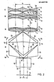
- Figure 2 shows a partial sectional view of the attachment lens according to the invention arranged according to the basic optics. which interacts optically with the lighting device.
- the stereoscopic image pair 10. 11 is recorded on the film running through the image plane 6. Such films usually have a width of 35 mm or 70 mm. The center distance on the two images 10, 11 is either the typical 13 mm or 26 mm. As described, the lighting device according to FIG. 1 is arranged behind the film. In the drawing, the optical axes for the two images 10, 11 are drawn in dash-dot lines.
- a so-called basic lens 12 is provided for the projection for each image, whereby this basic lens can be viewed optically as belonging to the projector to be equipped.
- Each of these basic objectives 12 is followed by a first prismatic part 21, 22, which consists of different optical materials and has the shape shown. The two partial prisms 21, 22 are cemented together.
- a second pair of prisms follows, which consists of the partial prisms 23, 24, which have a similar to the same shape and mode of operation as the first pair of prisms.
- the second pair of prisms 23, 24 is at a distance of 1 1 from the first pair of prisms 21, 22. This distance can either be lengthened or shortened, which is indicated by the double arrow 15.
- the mechanisms for such a shift of the pairs of prisms to one another are generally known and are not discussed in more detail here.
- the distance b can be increased or decreased. This depends on the width of the subsequent lens elements A, B, C.
- the pairs of prisms 21, 22 and 23, 24 can also be pivoted in their corresponding pivot point 13.
- this pivoting which is indicated by the double arrows 14, the convergence of the stereo images projected onto the spherical projection wall can be adjusted in such a way that they do not show the best stereo effect in a disturbing optical impression.
- the upper prism pairs 23, 24 shown in FIG. 2 are followed by an arrangement of three lens elements A, B, C for each of the two stereo images 10, 11. These lens elements have the same values for each image or for each image channel. Therefore, the reference numbers of the various design features of the elements are drawn only for the right arrangement. The following description and table also apply to the left arrangement.
- the first link is positive and also consists of a biconvex lens L 1 and a concave / convex lens L 2 . This is followed by an air space at a distance of 1 2 .
- the second link B has a negative effect and consists of a biconcave lens L 3 , biconvex lens L 4 and biconcave lens L 5 .
- the third lens unit C is separated from the second lens component by an air space B 1.
- the third lens element has a negative beam path and consists of a meniscus L 6 and a biconcave lens L 7 .
- the stereo image pair is projected with the base distance b onto the spherical projection surface, which is set up in the form of a hemisphere.
- r is the radius and d is the thickness of the individual lenses in mm. Just if the thicknesses 1 of the air spaces are given in mm.
- the refractive index n d relates to the helium line.
- v d denotes the Abbe number.
Landscapes
- Physics & Mathematics (AREA)
- General Physics & Mathematics (AREA)
- Lenses (AREA)
- Projection Apparatus (AREA)
- Testing, Inspecting, Measuring Of Stereoscopic Televisions And Televisions (AREA)
Abstract
Description
- Die Erfindung liegt im Gebiet der optischen Abbildung und betrifft ein Vorsatzobjektiv zur Projektion von stereoskopischen, anamorphotisch komprimierten Bildpaaren auf eine gekrümmte Breitwandfläche.
- Bei Filmaufführungen wird vielfach versucht, dem Betrachter den Eindruck zu vermitteln, er wäre in das lichtbildnerisch dargestellte Geschehen miteinbezogen. Die Attraktivität der möglichst wirklichkeitsnahen Darstellung eines meist optisch-dramatischen Ablaufs, wie beispielsweise auf den Betrachter zufliegenden Gegenstände, abschüssige Fahrten, die den Betrachter zu mannigfaltigen Reaktionen veranlassen, haben zu zahlreichen technischen Lösungen auf diesem Gebiet geführt.
- Sehr früh bemühte man sich, bei der kinomatographischen Darstellung einen räumlichen Eindruck zu erzeugen. Im Jahre 1909 wurde durch die FR-A-398'746 ein Verfahren mit Vorrichtung bekannt, um eine plastische Bildwirkung zu erhalten. Dazu wurden auf einen Film aufgenommene stereoskopische Bildpaare durch zwei zueinander geneigte Projektionsobjektive möglichst exakt überlagert projiziert. Der vorgeschlagene Projektor arbeitet mit zwei getrennten Lichtquellen. In einer vereinfachten Version wird vorgeschlagen, das Licht aus einer Quelle auf beide Objektive gleichmässig zu verteilen.Die Lichtausbeute war offensichtlich noch kein Thema.
- Weiterhin wurde durch die US-A-3 425 775 ein neuer Stereoprojektor für Breitwandprojektion bekannt. Während es damals üblich war, die mittels Zylinderanamorphoten bei der Aufnahme komprimierten Bildpaare, bei der Projektion wieder durch Zylinderanamorphoten zu dekomprimieren, wurde bei diesem Projektor diese Technik verlassen. Es wurden zur Dekompression Prismenanamorphoten von Brewster-Typ verwendet. Die daraus entstehenden Vorteile sind bekannt.
- Bei allen diesen Projektionen auf übergrosse Projektionsflächen tritt noch der Nachteil einer markant-geringen Lichtausbeute aus der Beleuchtungsvorrichtung auf. Dies hängt zu einem grossen Teil mit den Filtern zusammen, die einmal im Objektiv eines solchen Projektionsapparates angeordnet sind und mit den Polarisationsfiltern der Brille, die jeder Zuschauer trägt, in der ungefähr die Hälfte der Lichtausbeute pro Polarisationskanal verloren geht. Ausserdem sind die Projektionsflächen extrem gross, so dass die Bildausleuchtung nicht mehr als besonders gut zu bezeichnen ist. Man versuchte schon seit längerer Zeit, diesen Nachteil durch verstärkte Beleuchtungskörper zu überwinden. Nachteilig dabei ist, dass die Ausleuchtung eines stereoskopischen Bildpaares in der Filmebene ebenfalls Lichtverluste mit sich bringt.
- Es Ist Aufgabe der Erfindung, für die Wiedergabe von Weitwinkel-Stereobildern, bei der simultan die anamorphotische Dekompression durchgeführt wird, ein Vorsatzobjektiv für eine optische Einrichtung zu schaffen, die kleine Baulängen, wenig bewegliche Teile und für die Abbildung eine genügend hohe Lichtintensität aufweist. Ausserdem hat die Erfindung die Aufgabe, ein Vorsatzobjektiv zu schaffen. das für die Projektion von stereoskopischen Bildpaaren auf eine sphärische Projektionsfläche geeignet ist. Ferner Ist es Aufgabe der Erfindung, das Vorsatzobjektiv so auszugestalten, dass es an normale handelsübliche Projektoren angeordnet werden kann.
- Die Aufgabe wird durch das im kennzeichnenden Teil des Patentanspruchs 1 definierte Vorsatzobjektiv gelöst.
- Die Erfindung wird nun anhand des in den beiden Figuren dargestellten Ausführungsbeispiels näher erläutert. Es zeigen.
- Fig. 1 die Vorrichtung zur Beleuchtung von stereoskopischen Bildpaaren und
- Fig. 2 das Vorsatzobjektiv zur Projektion von stereoskopischen Bildpaaren auf eine sphärische Breitwandfläche.
- Wie schon erwähnt, kann mit dieser Einrichtung ein normaler handelsüblicher Kinoprojektor zu einer Projektionsvorrichtung für stereoskopische, anamorphotisch komprimierte Bildpaare auf extrem grosse, sphärisch gekrümmte Breitwandflächen aufgewertet werden. Das Problem besteht darin, die von den Lichtquellen abgegebene Energie im sichtbaren Spektrum möglichst quantitativ der Bildbühne zuzuführen und schliesslich die durchstrahlten Bildpaare anamorphotisch zu entzerren und bei genügender Lichtstärke auf die übergrosse Leinwand zu projizieren, also diese Leinwand voll auszuleuchten.
- Figur 1 zeigt in der Draufsicht die Beleuchtungsvorrichtung zur Beleuchtung von stereoskopischen Bildpaaren. Diese Vorrichtung besteht aus zwei Xenon-Hochdruckbogenlampen von z.B. je vier Kilowattleistung.
- Jede dieser Bogenlampen ist von einem Ellipsoidspiegel 2 so umgeben, dass die Lichtstrahlen, wie gestrichtelt angedeutet, in Richtung der optischen Achse 5 zum ersten Umlenkprisma 3 gelangen. Jeder der Ellipsoidspiegel besitzt die Brennweiten von im wesentlichen 60 mm und 540 mm. Der
- Durchmesser des Spiegels an seinem Rand beträgt ca. 280 mm. Die Figur zeigt ferner, dass die Bogenlampen 1 und Spiegel 2 symmetrisch zu einer Symmetrieebene 7 angeordnet sind. Der Winkel zwischen der Symmetrieebene 7 und den optischen Ach- sen 5 beträgt im vorliegenden Ausführungsbeispiel 18,5 . Selbstverständlich kann der Winkel je nach räumlichen Dimensionen eines Ausführungsbeispiels sich von diesem angegebenen Winkelwert unterscheiden. Das erste Umlenkprisma kann aus Quarz mit einem Keilwinkel von 19,56 oder aus dem Material "ZK N7" mit einem Keilwinkel von 17,5o ausgeführt werden. Bei der Quarzausführung beträgt die Brechzahl für die Heliumlinie nd = 1,458 und die Abbesche Zahl vd = ca. 67. Bei der Ausführung mit dem Material "ZK N7" beträgt die Brechzahl für die Heliumlinie nd = 1,5085 und Abbesche Zahl vd = 61,19. Für jeder der optischen Achsen ist ein erstes Umlenkprisma 3 vorgesehen. Die optische Achsenrichtung wird hierdurch auf einen Winkel von 9,3° zur Symmetrieebene 7 umgelenkt, was in der Zeichnung gestrichelt ist. Das Licht gelangt nun bereits eng gebündelt in den Bereich 8, der z.B. die mechanischen Blenden des Filmprojektors enthalten kann. Am Ende des Bereichs 8 befindet sich ein zweites Umlenkprisma 4, wobei für jede der optischen Achsen ein solches zweites Umlenkprisma vorgesehen ist. Dieses kann entweder aus Quarz mit der Brechzahl nd = 1,458 oder der Abbeschen Zahl v . 67 oder aus dem Material "Tempax" mit der Brechzahl nd = 1,485 und vd = ca. 62 bestehen.
- Im zweiten Umlenkprisma 4 aus "Tempax" mit einem Keilwinkel von 18,2° wird unmittelbar vor der Filmebene 6 die optische Beleuchtungsachse parallel zur Symmetrieebene 7 gerichtet. Der Lichtkegel wird durch einen sphärischen Hohlschliff im zweiten Umlenkprisma gestreckt. Dieser sphärische Hohlschliff ist auf der Seite des zweiten Umlenkprismas 4 angebracht. die zur Projektionsoptik 12 zeigt. Der Radius des Hohlschliffes ist im vorliegenden Beispiel r = 146 mm. Der optische Radius richtet sich nach der verwendeten Bogenlampe 1. In der Filmebene 6 wird das stereoskopische Bildpaar vollständig und optimal ausgeleuchtet. Beleuchtungsverluste treten nun nicht mehr auf.
- Figur 2 zeigt nun in teilweiser Schnittdarstellung das nach der Grundoptik angeordnete erfindungsgemässe Vorsatzobjektiv. welches mit der Beleuchtungsvorrichtung optisch zusammenwirkt.
- Auf den in der Bildebene 6 durchlaufenden Film Ist das stereoskopische Bildpaar 10. 11 aufgezeichnet. Ueblicherweise haben solche Filme eine Breite von 35 mm oder 70 mm. Der Mittenabstand an den beiden Bildern 10, 11 beträgt entweder die typischen 13 mm oder 26 mm. Hinter dem Film ist, wie beschrieben, die Beleuchtungsvorrichtung gemäss Figur 1 angeordnet. In der Zeichnung sind die optischen Achsen für die beiden Bilder 10, 11 strichpunktiert gezeichnet. Für jedes Bild ist ein sogenanntes Grundobjektiv 12 für die Projektion vorgesehen, wobei dieses Grundobjektiv optisch als dem auszurüstenden Projektor zugehörig betrachtet werden kann. Jedem dieser Grundobjektive 12 schliesst sich ein erstes Prismenpar 21, 22 an, das aus verschiedenen okptischen Materialien besteht und die dargestellte Form hat. Die beiden Teilprismen 21, 22 sind miteinander verkittet. Hierdurch wird die optische Achse der Lichtstrahlen nach rechts und links abgelenkt. In Richtung der Lichtstrahlen folgt nun ein zweites Prismenpaar, das aus den Teilprismen 23, 24 besteht, die eine ähnlich bis gleiche Form und auch Wirkungsweise haben wie das erste Prismenpaar. Das zweite Prismenpaar 23, 24 ist im Abstand 11 vom ersten Prismenpaar 21, 22 entfernt. Dieser Abstand kann entweder verlängert oder verkürzt werden, was durch den Doppelpfeil 15 angedeutet ist. Die Mechanismen zu einer solchen Verschiebung der Prismenpaare zueinander sind allgemein bekannt und werden hier nicht näher besprochen. Durch die Veränderung des Abstands 11 zwischen den Prismenpaaren kann die Strecke b vergrössert oder verringert werden. Dies hängt von der Baubreite der nachfolgenden Linsenglieder A, B, C ab. Die Prismenpaare 21, 22 und 23, 24 können ausserdem in ihrem entsprechenden Drehpunkt 13 verschwenkt werden. Durch diese Verschwenkung, die mittels der Doppelpfeile 14 angedeutet sind, kann die Konwergenz der auf die kugelförmige Projektionswand projizierten Stereobilder so einegestellt werden, dass sie chne einen störenden optischen Eindruch die beste Stereowirkung zeigen.
- Den in Figur 2 dargestellten oberen Prismenpaaren 23, 24 folgt für jedes der beiden Stereobilder 10, 11 eine Anordnung aus drei Linsengliedern A, B, C. Diese Linsenglieder haben die gleichen Werte für jedes Bild bzw. für jeden Bildkanal. Daher sind die Bezugszahlen der verschiedenen konstruktiven Merkmale der Linsen glieder nur für die rechte Anordnung gezeichnet. Die folgende Beschreibung und Tabelle gelten auch für die linke Anordnung. Das erste Glied ist positiv und besteht auch aus einer bikonvexen Linse L1 und einer konkav/konvex geformten Linse L2. Hieran schliesst sich ein Luftraum mit dem Abstand 12. Das zweite Glied B hat eine negative Wirkung und besteht aus einer bikonkaven Linse L3, bikonvexen Linse L4 und bikonkaven Linse L5. Das dritte Linsenglied C ist vom zweiten Linsenglied B durch einen Luftraum 13 getrennt. Das dritte Linsenglied hat einen negativen Strahlengang und besteht aus einem Meniskus L6 und aus einer bikonkav geformten Linse L7. Es folgen nun die bekannten Polarisationsfilter, die nicht dargestellt sind. Das Stereobildpaar wird mit den Basisabstand b auf die kugelförmige Projektionsfläche, die in Form einer Halbkugel aufgestellt ist, projiziert.
- Es folgt nun die Tabelle der konstruktiven Daten des dargestellten Objektivs:
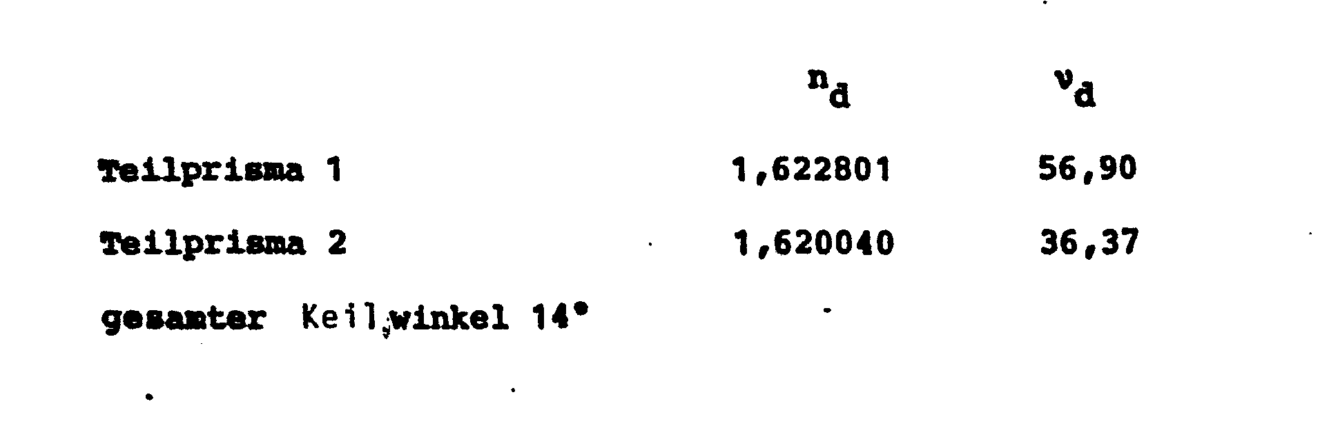

- In dieser Tabelle sind mit r die Radien und mit d die Dicken der einzelnen Linsen in mm angegeben. Ebenfalls sind die Dicken 1 der Lufträume in mm angegeben. Die Brechzahl nd bezieht sich auf die Helium-Linie. vd bezeichnet die Abbesche Zahl.
Claims (2)

Applications Claiming Priority (6)
| Application Number | Priority Date | Filing Date | Title |
|---|---|---|---|
| CH545281A CH655582B (de) | 1981-08-24 | 1981-08-24 | |
| CH5452/81 | 1981-08-24 | ||
| CH6177/81 | 1981-09-23 | ||
| CH617781 | 1981-09-23 | ||
| CH472582 | 1982-08-05 | ||
| CH4725/82 | 1982-08-05 |
Related Parent Applications (1)
| Application Number | Title | Priority Date | Filing Date |
|---|---|---|---|
| EP82902434.8 Division | 1983-03-09 |
Publications (3)
| Publication Number | Publication Date |
|---|---|
| EP0146770A2 true EP0146770A2 (de) | 1985-07-03 |
| EP0146770A3 EP0146770A3 (en) | 1985-07-31 |
| EP0146770B1 EP0146770B1 (de) | 1987-11-19 |
Family
ID=27174967
Family Applications (2)
| Application Number | Title | Priority Date | Filing Date |
|---|---|---|---|
| EP84113881A Expired EP0146770B1 (de) | 1981-08-24 | 1982-08-23 | Vorsatzobjektiv zur Projektion von stereoskopischen, anamorphotisch komprimierten Bildpaaren auf eine gekrümmte Breitwandfläche |
| EP82902434A Expired EP0086790B1 (de) | 1981-08-24 | 1982-08-23 | Einrichtung zur projektion von stereoskopischen, anamorphotisch komprimierten bildpaaren auf eine sphärisch gekrümmte breitwandfläche |
Family Applications After (1)
| Application Number | Title | Priority Date | Filing Date |
|---|---|---|---|
| EP82902434A Expired EP0086790B1 (de) | 1981-08-24 | 1982-08-23 | Einrichtung zur projektion von stereoskopischen, anamorphotisch komprimierten bildpaaren auf eine sphärisch gekrümmte breitwandfläche |
Country Status (5)
| Country | Link |
|---|---|
| US (1) | US4555168A (de) |
| EP (2) | EP0146770B1 (de) |
| BR (1) | BR8207829A (de) |
| DE (1) | DE3268409D1 (de) |
| WO (1) | WO1983000749A1 (de) |
Families Citing this family (14)
| Publication number | Priority date | Publication date | Assignee | Title |
|---|---|---|---|---|
| US5124840A (en) * | 1989-06-08 | 1992-06-23 | Trumbull Donald E | Portable viewing apparatus |
| US5126878A (en) * | 1989-06-08 | 1992-06-30 | Trumbull Donald E | Portable stereoscopic viewing apparatus |
| US5583694A (en) * | 1992-07-14 | 1996-12-10 | Nippon Telegraph And Telephone Corporation | Optical element and optical axis displacement device using the same |
| KR20010009720A (ko) * | 1999-07-13 | 2001-02-05 | 박호군 | 3차원 영상의 다자 시청용 스크린 및 그 제작방법 |
| US7843632B2 (en) * | 2006-08-16 | 2010-11-30 | Cymer, Inc. | EUV optics |
| KR20030010443A (ko) * | 2001-07-23 | 2003-02-05 | 홍광표 | 굴절 프리즘을 이용한 영상 확대용 광학 렌즈 및 이를이용한 광각 영상용안경 |
| US20110216157A1 (en) * | 2010-03-05 | 2011-09-08 | Tessera Technologies Ireland Limited | Object Detection and Rendering for Wide Field of View (WFOV) Image Acquisition Systems |
| KR20120057916A (ko) * | 2010-11-29 | 2012-06-07 | 최해용 | 입체 변환 확대 투사 광학계 |
| US8723959B2 (en) | 2011-03-31 | 2014-05-13 | DigitalOptics Corporation Europe Limited | Face and other object tracking in off-center peripheral regions for nonlinear lens geometries |
| US8493459B2 (en) | 2011-09-15 | 2013-07-23 | DigitalOptics Corporation Europe Limited | Registration of distorted images |
| WO2013067332A1 (en) * | 2011-11-02 | 2013-05-10 | Depalma Jeremy J | Stereoscopic viewer |
| US8928730B2 (en) | 2012-07-03 | 2015-01-06 | DigitalOptics Corporation Europe Limited | Method and system for correcting a distorted input image |
| JP6150717B2 (ja) * | 2013-12-05 | 2017-06-21 | オリンパス株式会社 | 立体撮像光学系、立体撮像装置及び内視鏡 |
| TWI555396B (zh) * | 2015-04-10 | 2016-10-21 | 晶睿通訊股份有限公司 | 發光模組及其影像監控裝置 |
Citations (2)
| Publication number | Priority date | Publication date | Assignee | Title |
|---|---|---|---|---|
| FR398746A (fr) | 1909-01-23 | 1909-06-12 | Louis Alexandre Cosme | Procédés et dispositifs pour obtenir des représentations cinématographiques plastiques, en relief et en profondeur |
| US3425775A (en) | 1965-10-21 | 1969-02-04 | Cct Cinema Camera Technik Ag | Stereo projector |
Family Cites Families (15)
| Publication number | Priority date | Publication date | Assignee | Title |
|---|---|---|---|---|
| FR962737A (de) * | 1950-06-19 | |||
| FR714994A (fr) * | 1931-04-09 | 1931-11-23 | Lentille à grand angle | |
| FR807183A (fr) * | 1936-06-05 | 1937-01-06 | Perfectionnements aux méthodes employées pour l'obtention de projections en couleurs et de projections stéréoscopiques | |
| US2184018A (en) * | 1937-04-08 | 1939-12-19 | Eastman Kodak Co | Lens attachment |
| US2307981A (en) * | 1940-08-03 | 1943-01-12 | Eastman Kodak Co | Setting-up slide for stereo projectors |
| US2810323A (en) * | 1953-10-28 | 1957-10-22 | Taylor Taylor & Hobson Ltd | Anamorphotic optical systems |
| GB747228A (en) * | 1954-04-12 | 1956-03-28 | Kenneth Roy Coleman | Improvements in or relating to anamorphotic optical systems |
| DE1045682B (de) * | 1954-12-10 | 1958-12-04 | Kamera Werke Niedersedlitz Veb | Vorsatzsystem zur Verkuerzung der Objektivbrennweite |
| DE1061091B (de) * | 1955-05-14 | 1959-07-09 | Rodenstock Optik G | Afokales Vorsatzsystem |
| US2854891A (en) * | 1956-10-01 | 1958-10-07 | Eastman Kodak Co | Reversible magnifying attachment for lenses |
| DE1168113B (de) * | 1959-05-30 | 1964-04-16 | Continental Elektro Ind Ag | Afokales Vorsatzsystem zur Verkuerzung der Brennweiten von vorzugsweise fotografischen Objektiven |
| US3152209A (en) * | 1961-04-28 | 1964-10-06 | Bell & Howell Co | Wide angle lens attachment |
| DE1180159B (de) * | 1962-09-01 | 1964-10-22 | Zeiss Carl Fa | Vierlinsiges afokales Vorsatzsystem zur Verkuerzung der Brennweite eines nach-geschalteten Objektivs |
| US3475086A (en) * | 1966-02-10 | 1969-10-28 | D 150 Inc | Cinema system utilizing a deeply curved screen and a mask for providing an illusion |
| CA980750A (en) * | 1972-09-15 | 1975-12-30 | Albert Jekste | Xenon light conversion system |
-
1982
- 1982-08-23 EP EP84113881A patent/EP0146770B1/de not_active Expired
- 1982-08-23 BR BR8207829A patent/BR8207829A/pt not_active IP Right Cessation
- 1982-08-23 EP EP82902434A patent/EP0086790B1/de not_active Expired
- 1982-08-23 US US06/488,540 patent/US4555168A/en not_active Expired - Lifetime
- 1982-08-23 WO PCT/CH1982/000099 patent/WO1983000749A1/de not_active Ceased
- 1982-08-23 DE DE8282902434T patent/DE3268409D1/de not_active Expired
Patent Citations (2)
| Publication number | Priority date | Publication date | Assignee | Title |
|---|---|---|---|---|
| FR398746A (fr) | 1909-01-23 | 1909-06-12 | Louis Alexandre Cosme | Procédés et dispositifs pour obtenir des représentations cinématographiques plastiques, en relief et en profondeur |
| US3425775A (en) | 1965-10-21 | 1969-02-04 | Cct Cinema Camera Technik Ag | Stereo projector |
Also Published As
| Publication number | Publication date |
|---|---|
| EP0146770A3 (en) | 1985-07-31 |
| BR8207829A (pt) | 1983-09-06 |
| DE3268409D1 (en) | 1986-02-20 |
| EP0086790B1 (de) | 1986-01-08 |
| EP0086790A1 (de) | 1983-08-31 |
| WO1983000749A1 (fr) | 1983-03-03 |
| EP0146770B1 (de) | 1987-11-19 |
| US4555168A (en) | 1985-11-26 |
Similar Documents
| Publication | Publication Date | Title |
|---|---|---|
| EP0146770B1 (de) | Vorsatzobjektiv zur Projektion von stereoskopischen, anamorphotisch komprimierten Bildpaaren auf eine gekrümmte Breitwandfläche | |
| DE1472179B1 (de) | Diaskop-Projektionsgeraet | |
| DE1497507C3 (de) | Optische Vorrichtung zum Projizieren einer Abbildung eines Objektes | |
| DE2409924A1 (de) | Vorrichtung zur herstellung einer vielfalt von projektionsbildern | |
| DE69518990T2 (de) | Linsenstruktur ohne sphärische aberration und stereoskopische kamera mit einer solchen linsenstruktur | |
| DE971992C (de) | Anamorphotisches Aufnahme- und Projektionsobjektiv mit Einrichtung zur Fokussierungauf beliebigem Objekt- bzw. Bildabstand | |
| DE3409043C2 (de) | ||
| DE561573C (de) | Beleuchtungseinrichtung fuer Bildwerfer | |
| DE3751148T2 (de) | Vorrichtung zur relativen erhöhung der tiefenschärfe und verbesserung des auflösungsvermögens bei vergrössernden systemen, insbesondere für mikroskope. | |
| DE1275304B (de) | Catadioptrisches Vergroesserungssystem | |
| DE131150C (de) | ||
| DE3410036C2 (de) | ||
| DE931869C (de) | Verfahren zum Herstellen und Projizieren von Filmen mit Panoramabildern und Projektionseinrichtung fuer nach diesem Verfahren hergestellte Filme | |
| DE2447595A1 (de) | Projektionsgeraet fuer fotogrammetrische zwecke | |
| AT101604B (de) | Einrichtung zur gleichzeitigen und fehlerfreien Aufnahme zweier in allen Teilen kongruenter Bilder desselben Aufnahmeobjektivs mit Hilfe der Spaltung des Lichtbüschels in zwei Teilbüschel. | |
| DE633864C (de) | Einrichtung zum optischen Kopieren von Linsenrasterfilmen | |
| DE736052C (de) | Kinematographisches Aufnahme- und Wiedergabeverfahren | |
| DE750942C (de) | Optisches System fuer farbige Photographie und Kinematographie | |
| AT101553B (de) | Optische Vorrichtung für Dreifarbenaufnahmen. | |
| DE1522019B2 (de) | Beleuchtungssystem für ein fotografisches Farbkopiergerät | |
| AT256512B (de) | Anordnung und Verfahren zum Herstellen von Schummerungen für kartographische Zwecke | |
| DE580612C (de) | Farbenkinematographische Aufnahmevorrichtung | |
| DE719206C (de) | Optisches Bildwerfersystem | |
| DE522643C (de) | Verfahren zur Herstellung von Projektionsbildern, insbesondere fuer Buehnenzwecke | |
| AT85301B (de) | Farbenkinematographie. |
Legal Events
| Date | Code | Title | Description |
|---|---|---|---|
| PUAI | Public reference made under article 153(3) epc to a published international application that has entered the european phase |
Free format text: ORIGINAL CODE: 0009012 |
|
| PUAL | Search report despatched |
Free format text: ORIGINAL CODE: 0009013 |
|
| AC | Divisional application: reference to earlier application |
Ref document number: 86790 Country of ref document: EP |
|
| AK | Designated contracting states |
Designated state(s): AT BE CH DE FR GB IT LI LU NL SE |
|
| AK | Designated contracting states |
Designated state(s): AT BE CH DE FR GB IT LI LU NL SE |
|
| 17P | Request for examination filed |
Effective date: 19850824 |
|
| 17Q | First examination report despatched |
Effective date: 19860929 |
|
| GRAA | (expected) grant |
Free format text: ORIGINAL CODE: 0009210 |
|
| AC | Divisional application: reference to earlier application |
Ref document number: 86790 Country of ref document: EP |
|
| AK | Designated contracting states |
Kind code of ref document: B1 Designated state(s): AT BE CH DE FR GB IT LI LU NL SE |
|
| PG25 | Lapsed in a contracting state [announced via postgrant information from national office to epo] |
Ref country code: NL Effective date: 19871119 Ref country code: IT Free format text: LAPSE BECAUSE OF FAILURE TO SUBMIT A TRANSLATION OF THE DESCRIPTION OR TO PAY THE FEE WITHIN THE PRESCRIBED TIME-LIMIT;WARNING: LAPSES OF ITALIAN PATENTS WITH EFFECTIVE DATE BEFORE 2007 MAY HAVE OCCURRED AT ANY TIME BEFORE 2007. THE CORRECT EFFECTIVE DATE MAY BE DIFFERENT FROM THE ONE RECORDED. Effective date: 19871119 Ref country code: BE Effective date: 19871119 |
|
| REF | Corresponds to: |
Ref document number: 30971 Country of ref document: AT Date of ref document: 19871215 Kind code of ref document: T |
|
| PG25 | Lapsed in a contracting state [announced via postgrant information from national office to epo] |
Ref country code: SE Effective date: 19871130 |
|
| GBT | Gb: translation of ep patent filed (gb section 77(6)(a)/1977) | ||
| REF | Corresponds to: |
Ref document number: 3277708 Country of ref document: DE Date of ref document: 19871223 |
|
| ET | Fr: translation filed | ||
| NLV1 | Nl: lapsed or annulled due to failure to fulfill the requirements of art. 29p and 29m of the patents act | ||
| PG25 | Lapsed in a contracting state [announced via postgrant information from national office to epo] |
Ref country code: AT Effective date: 19880823 |
|
| PG25 | Lapsed in a contracting state [announced via postgrant information from national office to epo] |
Ref country code: LU Free format text: LAPSE BECAUSE OF NON-PAYMENT OF DUE FEES Effective date: 19880831 |
|
| PLBE | No opposition filed within time limit |
Free format text: ORIGINAL CODE: 0009261 |
|
| STAA | Information on the status of an ep patent application or granted ep patent |
Free format text: STATUS: NO OPPOSITION FILED WITHIN TIME LIMIT |
|
| 26N | No opposition filed | ||
| PGFP | Annual fee paid to national office [announced via postgrant information from national office to epo] |
Ref country code: GB Payment date: 19990818 Year of fee payment: 18 |
|
| PGFP | Annual fee paid to national office [announced via postgrant information from national office to epo] |
Ref country code: CH Payment date: 19990820 Year of fee payment: 18 |
|
| PGFP | Annual fee paid to national office [announced via postgrant information from national office to epo] |
Ref country code: FR Payment date: 19990831 Year of fee payment: 18 |
|
| PGFP | Annual fee paid to national office [announced via postgrant information from national office to epo] |
Ref country code: DE Payment date: 19991021 Year of fee payment: 18 |
|
| PG25 | Lapsed in a contracting state [announced via postgrant information from national office to epo] |
Ref country code: GB Free format text: LAPSE BECAUSE OF NON-PAYMENT OF DUE FEES Effective date: 20000823 |
|
| PG25 | Lapsed in a contracting state [announced via postgrant information from national office to epo] |
Ref country code: LI Free format text: LAPSE BECAUSE OF NON-PAYMENT OF DUE FEES Effective date: 20000831 Ref country code: CH Free format text: LAPSE BECAUSE OF NON-PAYMENT OF DUE FEES Effective date: 20000831 |
|
| REG | Reference to a national code |
Ref country code: CH Ref legal event code: PL |
|
| GBPC | Gb: european patent ceased through non-payment of renewal fee |
Effective date: 20000823 |
|
| PG25 | Lapsed in a contracting state [announced via postgrant information from national office to epo] |
Ref country code: FR Free format text: LAPSE BECAUSE OF NON-PAYMENT OF DUE FEES Effective date: 20010430 |
|
| PG25 | Lapsed in a contracting state [announced via postgrant information from national office to epo] |
Ref country code: DE Free format text: LAPSE BECAUSE OF NON-PAYMENT OF DUE FEES Effective date: 20010501 |
|
| REG | Reference to a national code |
Ref country code: FR Ref legal event code: ST |