EP0142003A2 - Mélangeur de charge - Google Patents
Mélangeur de charge Download PDFInfo
- Publication number
- EP0142003A2 EP0142003A2 EP84111860A EP84111860A EP0142003A2 EP 0142003 A2 EP0142003 A2 EP 0142003A2 EP 84111860 A EP84111860 A EP 84111860A EP 84111860 A EP84111860 A EP 84111860A EP 0142003 A2 EP0142003 A2 EP 0142003A2
- Authority
- EP
- European Patent Office
- Prior art keywords
- opening
- flap
- housing
- mixer
- outside
- Prior art date
- Legal status (The legal status is an assumption and is not a legal conclusion. Google has not performed a legal analysis and makes no representation as to the accuracy of the status listed.)
- Granted
Links
Images


Classifications
-
- B—PERFORMING OPERATIONS; TRANSPORTING
- B01—PHYSICAL OR CHEMICAL PROCESSES OR APPARATUS IN GENERAL
- B01F—MIXING, e.g. DISSOLVING, EMULSIFYING OR DISPERSING
- B01F27/00—Mixers with rotary stirring devices in fixed receptacles; Kneaders
- B01F27/60—Mixers with rotary stirring devices in fixed receptacles; Kneaders with stirrers rotating about a horizontal or inclined axis
-
- B—PERFORMING OPERATIONS; TRANSPORTING
- B01—PHYSICAL OR CHEMICAL PROCESSES OR APPARATUS IN GENERAL
- B01F—MIXING, e.g. DISSOLVING, EMULSIFYING OR DISPERSING
- B01F35/00—Accessories for mixers; Auxiliary operations or auxiliary devices; Parts or details of general application
- B01F35/45—Closures or doors specially adapted for mixing receptacles; Operating mechanisms therefor
- B01F35/451—Closures or doors specially adapted for mixing receptacles; Operating mechanisms therefor by rotating them about an axis parallel to the plane of the opening
Definitions
- the invention relates to a batch mixer with a preferably horizontal mixing shaft in an approximately drum-shaped housing, the lower wall area of which is designed as at least one opening flap for emptying, the opening angle being greater than the angle of repose of the material to be mixed and the opening flap extending from the front to the front of the housing,
- Such a batch mixer has been proposed in the main application and has the considerable advantage with regard to the mixing function and above all with regard to its emptying that cleaning after emptying the dry material to be mixed is not necessary. This is achieved by the large opening angle, which exceeds the angle of repose of dry bulk material, so that no mixture can remain within the open housing of this mixer. A different mixture can therefore be processed in the mixer after the opening has been closed without this being adversely affected or influenced by the preceding mixture. From FR-PS 1 329 058 a drum-shaped mixer with a polygonal cross-section and with two jaw-shaped slide valves that can be opened in the shape of a mouth is already known, the entire mixer housing being rotated for the mixture.
- the mussel slide For their opening movement, the mussel slide must first be moved vertically downwards in order to be released from their sealing performance before they can then be folded sideways. On the one hand, this results in complex mechanics and, on the other hand, there is the risk that in this mixing drum, in which the opening angle is significantly smaller than the slope angle of dry mix, such material remains and, if necessary, even comes against the seal when the slide is closed.
- upstanding strips are provided on the inside of the slides, which should be pressed against the seal. Together with the outside of the slider, these strips form a single space in which mixed material can remain.
- Such a mixer is not suitable as a batch mixer for changing mixtures.
- the solution to this problem consists essentially in that at least the upper horizontal narrow side of the narrow flap located in the articulation area of the pivotable opening flap is formed obliquely in cross section and encloses an acute angle between itself and the outside of the opening flap that the housing opening has a matching counter slope as an attachment for the has sloping narrow side of the flap when the opening flap is closed and that in the region of this narrow side of the housing at a point remote from the interior of the housing there is a seal that is operatively connected to the closed opening flap.
- the oblique design of the upper horizontal narrow side of the opening flap ensures that when opening the flap this narrow side does not get into a horizontal, but rather a corresponding oblique position, so that no material can remain on it, which prevents the tight fitting when the flap is closed could.
- such an oblique joint has an overall better sealing effect, which is further improved and supported by the sealing strip.
- the sealing strip in the counter is inclined of the mixer housing, so that the oblique narrow side of the opening flap is in the closed position directly against this seal.
- a particularly favorable embodiment of the invention in which a seal can also be achieved if the inclined surface on the narrow side of the flap should be worn out by draining material, can consist in that the sealing strip is arranged or embedded on the outside of the housing adjacent to the counter slope and on the outside of the flap a pressure and counter bar is attached to this seal in the closed position.
- a corresponding sealing strip in particular, to be embedded in a groove both on the oblique narrow side and on the outside of the housing.
- the sealing strip is located on the "shadow side" of the housing with respect to the mix, so that it is not acted upon by the mix when the mix is discharged.
- the counter bar can be exchangeably and adjustably attached, in particular releasably, to the outside of the flap. This counter bar does not hinder the opening process if the pivot axis for the flap is arranged outside the housing and above the sealing joint. During the pivoting movement, the surfaces lying against one another then detach from one another before they are also pivoted away from one another. Conversely, when they close, they lay down practically without each other Friction against each other.
- sealing strip is incorporated next to the inclined surface of the flap and the flap with the acute-angled bevel on the outside preferably carries a counter strip for engaging the sealing strip.
- This counter bar in particular is exposed to a certain material closure when the flap is opened, so that it is advantageous if it can be replaced.
- the narrow sides of the flap can in turn be designed obliquely in such a way that the outside of the flap forms an acute angle with the narrow side, and on the container housing, the end wall can have a matching oblique mating surface on the circumference, which is pointed between the outside and the oblique surface Angle.
- a sealing strip arranged in the circumferential direction can be fastened between the inclined surface and the outer housing wall, and the flaps can preferably have interchangeable counter strips on their outer sides, which in the closed position bear against these sealing strips running in the circumferential direction.
- sealing strips are arranged around the housing opening in places that are not touched by the outflowing material, preferably embedded, which are overlapped by counter strips on the flap (s) in the closed position and below in their receiving groove or the like seat directed sealing pressure are set.
- the seals can also be interchangeably clamped in grooves.
- the Flap shape is adjustable, in particular in the area of the sealing strips in the sense of a largely uniform sealing effect. This can compensate for the loads on the flap, which could lead to loosening of the seal seat in certain areas.
- stiffening arms are arranged next to one another along the length of the flap, which have fastening points between them and the outside of the flap for spacer plates that can be used there.
- more or less spacer plates can be placed on the individual arms in order to have a secure system everywhere, even with heavy loads or deformation.
- the support arms for the flap have an angular or T-shaped cross-sectional profile, an angled leg or the T-crosspiece engaging the flap and allowing the spacer plates to be inserted between them and the flap.
- a batch mixer designated as a whole has a horizontal mixing shaft 2 which is acted upon by a coaxial drive motor 3 and is accommodated in a drum-shaped housing 4 according to FIG. 2.
- the lower wall area of this housing 4 can be opened for removal, two opening flaps 5 being wing-like to one another and pivotable away from one another.
- These opening flaps 5 practically form the lower wall area of the housing 4. They are so large that the opening angle of the housing opening is greater than the slope angle of dry mix. 1, the opening flaps 5 run from the front to the front of the housing 4. In this way, complete emptying of a mixer is possible without additional cleaning measures, because when the opening flaps 5 are opened, the dry mix from the mixer, for example, initially falls into an intermediate funnel 6 can, without projections or the like. On which residues of mixed material could remain.
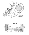
- the swiveling opening flap 5 are located in the joint area or in the region of the pivot axis 7 according to FIG. 3 upper horizontal narrow flap sides 8 are formed obliquely in cross section, an acute angle being formed between the narrow side 8 and the outer side 9 of the opening flap 5, which can be, for example, in the order of 55 °.
- the housing opening has a matching counter bevel 10 as a contact surface for the sloping flap narrow side 8 when the opening flap 5 is closed, as shown in FIG. 3.
- a seal 11 that is operatively connected to the closed opening flap 5 is arranged.
- the seal 11, which is designed as a sealing strip, could be embedded in the counter-bevels 10 of the mixer housing 4, so that the oblique narrow side 8 would contact the seal 11 in the closed position. With such an arrangement, the seal 11 is already on a "shadow side" opposite the outflowing mix.
- the sealing strip 11 is arranged and embedded in a groove 12 a and on the outside 9 of the opening flap 5, a pressure and counter strip 12 which engages over this seal 11 in the closed position is fastened.
- This counter bar 12 is detachable and replaceable and also adjustable by means of screws 13.
- the counter bar 12 can not hinder the opening process of the opening flap 5, since the pivot axis 7 for this flap 5 is arranged outside the housing 4 and above the sealing joint formed by the inclined surfaces 8 and 10 on the one hand and the seal 11 and the counter bar 12.
- the surfaces lying against one another first detach before they are swiveled away from one another. Conversely, when they close, they lay against each other practically without mutual friction.
- the opening flaps also have sloping narrow sides 14 in their contact area, and the opening flap 5, the sloping surface 14 of which forms an obtuse angle with the outside 9, has a sealing strip 11 in an area facing away from the mix, which cooperates with the other opening flap and its sealing surface.
- the sealing strip 11 is incorporated next to the inclined surface 14 of the flap 5 and the flap 5 with the acute-angled inclined surface 14 on its outside
- Counter bar 12 bears against the sealing bar 11, which in turn is interchangeable and also adjustable by means of screws 13.
- This counter bar 12 in the contact area of the two opening flaps 5 can be exposed to a certain flow of material when the flaps are opened, so that they may wear out faster, so that it is advantageous if they can be replaced quickly.
- the seal in the area of the end faces of the mixer 1 is illustrated particularly in FIG. 4.
- inclined surfaces 16 can be seen which form an acute angle with respect to the outside 17.
- the opening flaps also have an inclined surface 18 in this area, which runs at an acute angle to their outside, the two inclined surfaces 16 and 18 matching each other in such a way that the closed opening flap 5 is mitred with this end wall region, as is the right part of FIG Fig. 4 illustrates.
- an outer housing wall section 19 is also provided, which projects downward beyond the flap end faces. This can pass into the funnel 6.
- Interchangeable mating strips, which bear against these sealing strips 20 in the closed position, can in turn be attached to the flap outer sides.
- these counter strips running parallel to the end faces are not visible, since they run from the longitudinal section through the counter bar 12 are concealed at the opening area of the two flaps. However, they can be connected directly to this sealing strip 12 on the end faces.
- sealing strips 11 and 20 are arranged and embedded around the very large housing opening at all points that are not touched by the outflowing material, which overlap with counter strips 12 on the flaps 5 in the closed position and under in their receiving groove 12 or 21 directional seal pressure. These sealing strips can also be replaced if they have aged or their sealing effect is weakening for other reasons. Elaborate labyrinth seals u. The like are avoided. This results in a mixer housing 4, which is dust-tight and maintains its tightness even at high pressures during the mixing process, but nevertheless has a very large outlet opening.
- the flap shape can be adjusted in particular in the area of the sealing strips 12 and 21 in the sense of a largely uniform sealing effect.
- stiffening arms 22 are arranged next to one another at a distance from the joint axis 7 over the length of the opening flaps 5. These are connected to the opening flaps 5 in a manner yet to be described and transmit the forces from working cylinders 23 to the flaps, these cylinders 23 each acting on the hinge axis 7 with a lever arm 24 according to FIG. 2.
- spacer plates 25 that can be used there.
- spacer plates 25 can be placed on the individual arms 22 in order to compensate for deformations of the opening flaps that occur during production or under load, and a secure system in particular everywhere effect in the sealing area.
- the support arms 22 can have an angular or T-shaped cross-sectional profile, an angle leg or the T-crosspiece engaging the flap 5 and allowing the spacer plates 25 to be inserted between them and the flap.
- This is a very simple and practical design for bracing and adapting the flaps to high loads or to compensate for any deformations that may occur.
Landscapes
- Chemical & Material Sciences (AREA)
- Chemical Kinetics & Catalysis (AREA)
- Mixers Of The Rotary Stirring Type (AREA)
- Processing Of Solid Wastes (AREA)
- Accessories For Mixers (AREA)
- Preparation Of Clay, And Manufacture Of Mixtures Containing Clay Or Cement (AREA)
- Processing And Handling Of Plastics And Other Materials For Molding In General (AREA)
- Transition And Organic Metals Composition Catalysts For Addition Polymerization (AREA)
- Mixers With Rotating Receptacles And Mixers With Vibration Mechanisms (AREA)
Priority Applications (1)
| Application Number | Priority Date | Filing Date | Title |
|---|---|---|---|
| AT84111860T ATE26929T1 (de) | 1983-10-14 | 1984-10-04 | Chargenmischer. |
Applications Claiming Priority (2)
| Application Number | Priority Date | Filing Date | Title |
|---|---|---|---|
| DE19833337437 DE3337437A1 (de) | 1983-10-14 | 1983-10-14 | Chargenmischer |
| DE3337437 | 1983-10-14 |
Publications (4)
| Publication Number | Publication Date |
|---|---|
| EP0142003A2 true EP0142003A2 (fr) | 1985-05-22 |
| EP0142003A3 EP0142003A3 (en) | 1985-08-14 |
| EP0142003B1 EP0142003B1 (fr) | 1987-05-06 |
| EP0142003B2 EP0142003B2 (fr) | 1994-01-12 |
Family
ID=6211860
Family Applications (1)
| Application Number | Title | Priority Date | Filing Date |
|---|---|---|---|
| EP84111860A Expired - Lifetime EP0142003B2 (fr) | 1983-10-14 | 1984-10-04 | Mélangeur de charge |
Country Status (10)
| Country | Link |
|---|---|
| US (1) | US4572674A (fr) |
| EP (1) | EP0142003B2 (fr) |
| JP (1) | JPS6097033A (fr) |
| KR (2) | KR850003333A (fr) |
| AT (1) | ATE26929T1 (fr) |
| AU (1) | AU562893B2 (fr) |
| CA (1) | CA1225389A (fr) |
| DE (2) | DE3337437A1 (fr) |
| ES (1) | ES536650A0 (fr) |
| ZA (1) | ZA847708B (fr) |
Cited By (1)
| Publication number | Priority date | Publication date | Assignee | Title |
|---|---|---|---|---|
| EP0685255A1 (fr) * | 1994-04-29 | 1995-12-06 | Bühler Ag | Sortie de mélangeur continu |
Families Citing this family (16)
| Publication number | Priority date | Publication date | Assignee | Title |
|---|---|---|---|---|
| JPS62201625A (ja) * | 1986-02-28 | 1987-09-05 | Chichibu Eng Kk | 振動式2軸強制練りミキサ |
| DE4002099A1 (de) * | 1990-01-25 | 1991-08-01 | Draiswerke Gmbh | Mischer |
| US5810475A (en) * | 1996-09-16 | 1998-09-22 | Brownwood Ross Company, Inc. | Single discharge door for continuous or batching operation of twin-shaft twin-trough mixers |
| DE29621448U1 (de) * | 1996-12-10 | 1997-02-06 | Liebherr-Mischtechnik Gmbh, 88427 Bad Schussenried | Verschluß |
| RU2133144C1 (ru) * | 1997-10-28 | 1999-07-20 | Муниципальное предприятие "РЕМСТРОЙБЛАГОУСТРОЙСТВО" | Перемешивающее устройство |
| DE29804378U1 (de) | 1998-03-12 | 1998-06-04 | m-tec mathis technik gmbh, 79395 Neuenburg | Schüttgutbehälter mit einer um eine Achse schwenkbaren Öffnungsklappe |
| DE19813867C2 (de) * | 1998-03-28 | 2000-03-23 | Loedige Maschbau Gmbh Geb | Vorrichtung zur Herstellung von Feststoff- und/oder Feststoff-Flüssigkeits-Mischungen |
| DE19957934A1 (de) * | 1999-12-01 | 2001-11-15 | Lehmann Maschb Gmbh | Chargenmischer mit Dosiervorrichtung |
| KR100734349B1 (ko) * | 2000-11-17 | 2007-07-03 | 엘지전자 주식회사 | 회전가능한 배플을 갖는 드럼세탁기 |
| EP1527811A1 (fr) * | 2003-10-30 | 2005-05-04 | WAM S.p.A. | Dispositif de mélange et transport pour poudres et pour mélanges de poudre et liquide |
| DE102004014834A1 (de) * | 2004-03-24 | 2005-10-13 | Elba-Werk Maschinen-Gesellschaft Mbh | Maschinenklappenbetätigung |
| CN100560194C (zh) * | 2005-10-28 | 2009-11-18 | 鸿富锦精密工业(深圳)有限公司 | 散热膏混合装置 |
| US7878700B2 (en) * | 2008-09-23 | 2011-02-01 | Equistar Chemicals, Lp | Polymer removal from a polymer mixer |
| US20110204611A1 (en) * | 2010-02-18 | 2011-08-25 | Daimler Trucks North America Llc | Fiber reinforced polymer frame rail |
| USD684811S1 (en) * | 2011-02-18 | 2013-06-25 | Buhler Ag | Batch mixer |
| CN106110999A (zh) * | 2016-08-02 | 2016-11-16 | 肇庆千江高新材料科技股份公司 | 一种免洗搅拌缸 |
Family Cites Families (13)
| Publication number | Priority date | Publication date | Assignee | Title |
|---|---|---|---|---|
| DE311116C (fr) * | ||||
| US3128901A (en) * | 1964-04-14 | Agnon | ||
| DE8226167U1 (de) * | 1982-12-16 | C. F. Maier GmbH & Co, 7923 Königsbronn | Großbehälter zum Sammeln von Altmaterial, insbesondere von Altpapier | |
| DE725208C (de) * | 1940-09-10 | 1942-09-17 | Buehler G M B H Geb | Tellerschleuse fuer Schuettgut |
| US2835269A (en) * | 1953-04-10 | 1958-05-20 | Smith Corp A O | Vessel closure |
| CH345593A (de) * | 1956-06-08 | 1960-03-31 | Theodor Kokeisl | Silo |
| CH349477A (de) * | 1957-02-28 | 1960-10-15 | Buehler Ag Geb | Chargenmischer |
| FR1329058A (fr) * | 1962-04-27 | 1963-06-07 | Bétonnière perfectionnée | |
| US3352542A (en) * | 1966-06-29 | 1967-11-14 | Stewart Bolling & Company Inc | Mixing machine |
| US4075713A (en) * | 1976-11-11 | 1978-02-21 | Easton Harlan J | Feed mixer |
| DE2903951C3 (de) * | 1979-02-02 | 1985-01-03 | Eirich, Hubert | Vorrichtung zum Verschließen einer Entleerungsöffnung in einem Behälterboden |
| US4462693A (en) * | 1980-01-25 | 1984-07-31 | Veda, Inc. | Material mixing apparatus |
| DE3236780C2 (de) * | 1982-10-05 | 1984-09-06 | Mathis System-Technik GmbH, 7844 Neuenburg | Misch- und Verladevorrichtung für Mischungen aus pulverigen und/oder körnigen Feststoffen |
-
1983
- 1983-10-14 DE DE19833337437 patent/DE3337437A1/de not_active Withdrawn
-
1984
- 1984-10-01 ZA ZA847708A patent/ZA847708B/xx unknown
- 1984-10-04 EP EP84111860A patent/EP0142003B2/fr not_active Expired - Lifetime
- 1984-10-04 AT AT84111860T patent/ATE26929T1/de not_active IP Right Cessation
- 1984-10-04 DE DE8484111860T patent/DE3463452D1/de not_active Expired
- 1984-10-10 ES ES536650A patent/ES536650A0/es active Granted
- 1984-10-11 AU AU34139/84A patent/AU562893B2/en not_active Ceased
- 1984-10-12 CA CA000465248A patent/CA1225389A/fr not_active Expired
- 1984-10-13 KR KR1019840006351A patent/KR850003333A/ko not_active Withdrawn
- 1984-10-15 US US06/661,111 patent/US4572674A/en not_active Expired - Fee Related
- 1984-10-15 JP JP59214453A patent/JPS6097033A/ja active Pending
-
1987
- 1987-06-26 KR KR2019870010294U patent/KR880000478Y1/ko not_active Expired
Cited By (1)
| Publication number | Priority date | Publication date | Assignee | Title |
|---|---|---|---|---|
| EP0685255A1 (fr) * | 1994-04-29 | 1995-12-06 | Bühler Ag | Sortie de mélangeur continu |
Also Published As
| Publication number | Publication date |
|---|---|
| KR880000478Y1 (ko) | 1988-03-12 |
| CA1225389A (fr) | 1987-08-11 |
| DE3463452D1 (en) | 1987-06-11 |
| EP0142003B2 (fr) | 1994-01-12 |
| EP0142003A3 (en) | 1985-08-14 |
| AU562893B2 (en) | 1987-06-18 |
| ES8603144A1 (es) | 1985-12-16 |
| AU3413984A (en) | 1985-04-18 |
| US4572674A (en) | 1986-02-25 |
| ATE26929T1 (de) | 1987-05-15 |
| KR850003333A (ko) | 1985-06-17 |
| JPS6097033A (ja) | 1985-05-30 |
| EP0142003B1 (fr) | 1987-05-06 |
| ZA847708B (en) | 1985-05-29 |
| ES536650A0 (es) | 1985-12-16 |
| DE3337437A1 (de) | 1985-05-02 |
Similar Documents
| Publication | Publication Date | Title |
|---|---|---|
| EP0142003B1 (fr) | Mélangeur de charge | |
| EP0336081A2 (fr) | Véhicule à ordures | |
| DE3344531A1 (de) | Mischvorrichtung | |
| DE3326247C2 (de) | Vorrichtung zum kontinuierlichen Mischen eines Schüttgutes | |
| DE69410401T2 (de) | Bandförderer, insbesondere für einen Transportbetonmischer | |
| DE1803819C3 (de) | Betonpumpe | |
| DE3624867C2 (fr) | ||
| DE1114423B (de) | Transportmischer fuer Beton und andere Baustoffe | |
| DE2848437C3 (de) | Verstellbare Bandübergabe | |
| DE19703495A1 (de) | Trogmischer, insbesondere Doppelwellen-Trogmischer | |
| CH678312A5 (fr) | ||
| DE3911424C2 (fr) | ||
| DE3208290A1 (de) | Betonausbreitvorrichtung | |
| DE2403078C2 (de) | Behälter für Massengüter | |
| EP0941947B1 (fr) | Récipient à produits en vrac avec porte d'ouverture à rabattre pivotante autour d'un axe | |
| DE19649493C1 (de) | Innenmischer zur Verarbeitung von Kautschuk- oder kautschukähnlichen Kunststoffmischungen | |
| DE2433107C3 (de) | Rundschieberverschluß für Entladungsfahrzeuge | |
| DE19813867A1 (de) | Vorrichtung zur Herstellung von Feststoff- und/oder Feststoff-Flüssigkeits-Mischungen | |
| DE2937324C2 (de) | Schleudervorrichtung zum Aufbringen einer Betonmischung od.dgl. auf eine Oberfläche | |
| DE2908778A1 (de) | Absperrorgan, insbesondere schieber | |
| DE8913720U1 (de) | Zellenradschleuse | |
| DE20118974U1 (de) | Fahrbare Straßenoberflächen-Beschichtungseinrichtung | |
| DE2902853B1 (de) | Rotationszellendosierer und -verschluss | |
| DE69016010T2 (de) | Mischtransportapparat für Bodenmörtel und dergleichen. | |
| DE2425508C3 (de) | Aufgabebunker |
Legal Events
| Date | Code | Title | Description |
|---|---|---|---|
| PUAI | Public reference made under article 153(3) epc to a published international application that has entered the european phase |
Free format text: ORIGINAL CODE: 0009012 |
|
| AK | Designated contracting states |
Designated state(s): AT BE CH DE FR GB IT LI LU NL SE |
|
| PUAL | Search report despatched |
Free format text: ORIGINAL CODE: 0009013 |
|
| AK | Designated contracting states |
Designated state(s): AT BE CH DE FR GB IT LI LU NL SE |
|
| 17P | Request for examination filed |
Effective date: 19850725 |
|
| 17Q | First examination report despatched |
Effective date: 19860317 |
|
| RIN1 | Information on inventor provided before grant (corrected) |
Inventor name: MATHIS, BERNAHRD Inventor name: MATHIS, FRANZ Inventor name: ZIMMER, MAX Inventor name: MATHIS, PAUL |
|
| RAP1 | Party data changed (applicant data changed or rights of an application transferred) |
Owner name: M-TEC MATHIS TECHNIK GMBH |
|
| ITF | It: translation for a ep patent filed | ||
| GRAA | (expected) grant |
Free format text: ORIGINAL CODE: 0009210 |
|
| AK | Designated contracting states |
Kind code of ref document: B1 Designated state(s): AT BE CH DE FR GB IT LI LU NL SE |
|
| REF | Corresponds to: |
Ref document number: 26929 Country of ref document: AT Date of ref document: 19870515 Kind code of ref document: T |
|
| REF | Corresponds to: |
Ref document number: 3463452 Country of ref document: DE Date of ref document: 19870611 |
|
| ET | Fr: translation filed | ||
| PLBI | Opposition filed |
Free format text: ORIGINAL CODE: 0009260 |
|
| 26 | Opposition filed |
Opponent name: GEBR. LOEDIGE MASCHINENBAU-GESELLSCHAFT MBH Effective date: 19880205 Opponent name: BHS - BAYERISCHE BERG-, HUETTEN- UND SALZWERKE AG Effective date: 19880204 |
|
| NLR1 | Nl: opposition has been filed with the epo |
Opponent name: GEBR. LOEDIGE MASCHINENBAU-GESELLSCHAFT MBH Opponent name: BHS - BAYERISCHE BERG-, HUETTEN- UND SALZWERKE AG |
|
| PGFP | Annual fee paid to national office [announced via postgrant information from national office to epo] |
Ref country code: SE Payment date: 19910924 Year of fee payment: 8 |
|
| PGFP | Annual fee paid to national office [announced via postgrant information from national office to epo] |
Ref country code: CH Payment date: 19911004 Year of fee payment: 8 |
|
| PGFP | Annual fee paid to national office [announced via postgrant information from national office to epo] |
Ref country code: LU Payment date: 19911028 Year of fee payment: 8 |
|
| ITTA | It: last paid annual fee | ||
| PGFP | Annual fee paid to national office [announced via postgrant information from national office to epo] |
Ref country code: NL Payment date: 19911031 Year of fee payment: 8 Ref country code: AT Payment date: 19911031 Year of fee payment: 8 |
|
| PGFP | Annual fee paid to national office [announced via postgrant information from national office to epo] |
Ref country code: BE Payment date: 19911211 Year of fee payment: 8 |
|
| EPTA | Lu: last paid annual fee | ||
| PG25 | Lapsed in a contracting state [announced via postgrant information from national office to epo] |
Ref country code: LU Free format text: LAPSE BECAUSE OF NON-PAYMENT OF DUE FEES Effective date: 19921004 Ref country code: AT Effective date: 19921004 |
|
| PG25 | Lapsed in a contracting state [announced via postgrant information from national office to epo] |
Ref country code: SE Effective date: 19921005 |
|
| PG25 | Lapsed in a contracting state [announced via postgrant information from national office to epo] |
Ref country code: LI Effective date: 19921031 Ref country code: CH Effective date: 19921031 Ref country code: BE Effective date: 19921031 |
|
| BERE | Be: lapsed |
Owner name: M-TEC MATHIS TECHNIK G.M.B.H. Effective date: 19921031 |
|
| PG25 | Lapsed in a contracting state [announced via postgrant information from national office to epo] |
Ref country code: NL Effective date: 19930501 |
|
| NLV4 | Nl: lapsed or anulled due to non-payment of the annual fee | ||
| REG | Reference to a national code |
Ref country code: CH Ref legal event code: PL |
|
| ITF | It: translation for a ep patent filed | ||
| PUAH | Patent maintained in amended form |
Free format text: ORIGINAL CODE: 0009272 |
|
| STAA | Information on the status of an ep patent application or granted ep patent |
Free format text: STATUS: PATENT MAINTAINED AS AMENDED |
|
| 27A | Patent maintained in amended form |
Effective date: 19940112 |
|
| AK | Designated contracting states |
Kind code of ref document: B2 Designated state(s): AT BE CH DE FR GB IT LI LU NL SE |
|
| ET3 | Fr: translation filed ** decision concerning opposition | ||
| PGFP | Annual fee paid to national office [announced via postgrant information from national office to epo] |
Ref country code: GB Payment date: 19940930 Year of fee payment: 11 Ref country code: FR Payment date: 19940930 Year of fee payment: 11 |
|
| EUG | Se: european patent has lapsed |
Ref document number: 84111860.7 Effective date: 19930510 |
|
| PGFP | Annual fee paid to national office [announced via postgrant information from national office to epo] |
Ref country code: DE Payment date: 19950921 Year of fee payment: 12 |
|
| PG25 | Lapsed in a contracting state [announced via postgrant information from national office to epo] |
Ref country code: GB Effective date: 19951004 |
|
| GBPC | Gb: european patent ceased through non-payment of renewal fee |
Effective date: 19951004 |
|
| PG25 | Lapsed in a contracting state [announced via postgrant information from national office to epo] |
Ref country code: FR Effective date: 19960628 |
|
| REG | Reference to a national code |
Ref country code: FR Ref legal event code: ST |
|
| APAC | Appeal dossier modified |
Free format text: ORIGINAL CODE: EPIDOS NOAPO |
|
| APAC | Appeal dossier modified |
Free format text: ORIGINAL CODE: EPIDOS NOAPO |
|
| PG25 | Lapsed in a contracting state [announced via postgrant information from national office to epo] |
Ref country code: DE Effective date: 19970701 |
|
| APAH | Appeal reference modified |
Free format text: ORIGINAL CODE: EPIDOSCREFNO |