EP0142003B2 - Mélangeur de charge - Google Patents
Mélangeur de charge Download PDFInfo
- Publication number
- EP0142003B2 EP0142003B2 EP84111860A EP84111860A EP0142003B2 EP 0142003 B2 EP0142003 B2 EP 0142003B2 EP 84111860 A EP84111860 A EP 84111860A EP 84111860 A EP84111860 A EP 84111860A EP 0142003 B2 EP0142003 B2 EP 0142003B2
- Authority
- EP
- European Patent Office
- Prior art keywords
- opening
- flap
- mixer
- housing
- outside
- Prior art date
- Legal status (The legal status is an assumption and is not a legal conclusion. Google has not performed a legal analysis and makes no representation as to the accuracy of the status listed.)
- Expired - Lifetime
Links
- 238000007789 sealing Methods 0.000 claims abstract description 44
- 239000000463 material Substances 0.000 claims abstract description 18
- 125000006850 spacer group Chemical group 0.000 claims description 9
- 230000001154 acute effect Effects 0.000 claims description 8
- 230000013011 mating Effects 0.000 claims description 8
- 230000000694 effects Effects 0.000 claims description 6
- 238000012856 packing Methods 0.000 claims 14
- 230000002093 peripheral effect Effects 0.000 claims 1
- 230000000295 complement effect Effects 0.000 abstract description 2
- 230000009969 flowable effect Effects 0.000 abstract 1
- 239000011343 solid material Substances 0.000 abstract 1
- 239000000203 mixture Substances 0.000 description 26
- 238000004140 cleaning Methods 0.000 description 5
- 238000000034 method Methods 0.000 description 5
- 238000010276 construction Methods 0.000 description 4
- 238000004519 manufacturing process Methods 0.000 description 4
- 230000015572 biosynthetic process Effects 0.000 description 2
- 239000004570 mortar (masonry) Substances 0.000 description 2
- 230000002411 adverse Effects 0.000 description 1
- 239000013590 bulk material Substances 0.000 description 1
- 239000000470 constituent Substances 0.000 description 1
- 239000000428 dust Substances 0.000 description 1
- 230000003628 erosive effect Effects 0.000 description 1
- 230000002349 favourable effect Effects 0.000 description 1
- 230000001771 impaired effect Effects 0.000 description 1
- 230000036961 partial effect Effects 0.000 description 1
- 239000011505 plaster Substances 0.000 description 1
- 230000002829 reductive effect Effects 0.000 description 1
- 230000000717 retained effect Effects 0.000 description 1
- XLYOFNOQVPJJNP-UHFFFAOYSA-N water Substances O XLYOFNOQVPJJNP-UHFFFAOYSA-N 0.000 description 1
- 230000003313 weakening effect Effects 0.000 description 1
Images

Classifications
-
- B—PERFORMING OPERATIONS; TRANSPORTING
- B01—PHYSICAL OR CHEMICAL PROCESSES OR APPARATUS IN GENERAL
- B01F—MIXING, e.g. DISSOLVING, EMULSIFYING OR DISPERSING
- B01F35/00—Accessories for mixers; Auxiliary operations or auxiliary devices; Parts or details of general application
- B01F35/45—Closures or doors specially adapted for mixing receptacles; Operating mechanisms therefor
- B01F35/451—Closures or doors specially adapted for mixing receptacles; Operating mechanisms therefor by rotating them about an axis parallel to the plane of the opening
-
- B—PERFORMING OPERATIONS; TRANSPORTING
- B01—PHYSICAL OR CHEMICAL PROCESSES OR APPARATUS IN GENERAL
- B01F—MIXING, e.g. DISSOLVING, EMULSIFYING OR DISPERSING
- B01F27/00—Mixers with rotary stirring devices in fixed receptacles; Kneaders
- B01F27/60—Mixers with rotary stirring devices in fixed receptacles; Kneaders with stirrers rotating about a horizontal or inclined axis
Definitions
- the invention relates to a batch mixer with an approximately drum-shaped housing and preferably with a horizontal mixing shaft, the lower wall area of which is designed as at least one opening flap which can be pivoted about a pivot axis for emptying.
- Such a batch mixer is known from CH-A-349 477.
- the lower part of this batch mixer is designed as a folding door.
- the sealing of this folding door must be regarded as difficult and expensive due to its considerable size, but is not explained in this document.
- the opening angle of the opening closed by this folding door is greater than the angle of repose of the mixed material. Due to the size relationships that result from the drawing of this document, it is at most disclosed that the opening angle is smaller than the slope angle of dry mix, so that when emptying mix remains in the mixer housing and can only be removed by additional measures.
- EP-A-0 105 107 (filing date: July 20, 1983; priority October 5, 1982; publication date: April 11, 1984) describes a mixing device to which a batch mixer of the type mentioned at the beginning belongs, in which the opening angle is greater than the slope angle of the mix and the opening flap extends from the front to the front of the housing.
- the batch mixer provided here has the considerable advantage, particularly with regard to its emptying, that cleaning after emptying the material to be mixed is not necessary. This is achieved by the angle of repose of dry bulk material which exceeds the large opening angle, because no mixture can remain within the open housing of this mixer. A different mixture can be processed than the closing of the opening in the mixer without this previous mixture being impaired or influenced.
- FR-A-1 329 058 also discloses a drum-shaped mixer with a polygonal cross section of the mixer housing and two jaw-shaped slide valves which can be opened in the form of a jaw, the entire mixer housing being rotated during the mixing process. It is a concrete mixing machine with which a mix is to be mixed with water, so that a material-specific slope angle is irrelevant. Furthermore, the problem that mixtures of different compositions should be able to be produced in succession plays no role. without a previous mixture falsifying the next one in its composition.
- Batch mixers for dry goods have a relatively high internal pressure, especially if the mixer is of a suitable size for good performance. Numerous batch mixers are therefore also known from practice which have only relatively small openings so that they are not subjected to correspondingly high forces. Even then, residue-free emptying is not possible without additional cleaning measures.
- the batch mixer of the type mentioned with a lower openable wall area is characterized in that the opening angle is greater than the angle of repose of the material to be mixed and the opening flap extends from face to face of the housing, that at least that located in the region of the pivot axis of the opening flap , horizontally extending narrow side of the flap is oblique in cross-section and encloses an acute angle between itself and the outside of the opening flap, that the housing opening has a matching counter slope as an attachment for the sloping narrow side of the flap when the opening flap is closed and that in the area of this narrow side on the housing at one of the A seal that is operatively connected to the closed opening flap is arranged inside the housing.
- the oblique design of the upper horizontal narrow side of the opening flap ensures that when opening the flap this narrow side does not get into a horizontal, but rather a corresponding oblique position, so that no material can remain on it, which prevents the tight fitting when the flap is closed could.
- such an inclined joint has a better sealing effect overall, which is further improved and supported by the sealing strip.
- sealing strip is embedded in the counter-bevel of the mixer housing, so that the oblique narrow side of the opening flap directly contacts this seal in the closed position.
- a particularly favorable embodiment of the invention in which a seal can also be achieved if the inclined surface on the narrow side of the flap should be worn out by draining material, can consist of being adjacent on the outside of the housing to the counter slope, the sealing strip is arranged or embedded, and a pressure and counter strip that engages over this seal in the closed position is attached to the outside of the flap.
- a corresponding sealing strip in particular, to be embedded in a groove both on the oblique narrow side and on the outside of the housing.
- the sealing strip is located opposite the mix on a "shadow side" of the housing, so that it is not acted upon by the mix when it is discharged.
- the counter bar can be exchangeably and adjustably attached, in particular releasably, to the outside of the flap. This counter bar does not hinder the opening process if the pivot axis for the flap is arranged outside the housing and above the sealing joint. During the pivoting movement, the surfaces lying against one another then detach from one another before they are also pivoted away from one another. Conversely, when they close, they rest against each other practically without mutual friction.
- sealing strip is incorporated next to the inclined surface of the flap and the flap with the acute-angled bevel on the outside preferably carries a mating strip for engaging the sealing strip.
- this counter bar is exposed to a certain material closure when the flap is opened, so that it is advantageous if it can be replaced.
- the narrow sides of the flap can in turn be formed obliquely in such a way that the outside of the flap forms an acute angle with the narrow side, and on the container housing, the end wall can have a matching oblique counter surface all around on the circumference, which is pointed between the outside and the oblique surface Angle.
- an outer housing wall section can also be provided, which projects downward beyond the flap end face. This stabilizes the entire housing in this area.
- a sealing strip arranged in the circumferential direction can be fastened between the inclined surface and the outer housing wall, and the flaps can preferably have interchangeable counter strips on their outer sides, which in the closed position bear against these sealing strips running in the circumferential direction.
- sealing strips are arranged around the housing opening in places that are not touched by the outflowing material, preferably embedded, which are overlapped by counter strips on the flap (s) in the closed position and below in their receiving groove or the like seat directed sealing pressure are set.
- the seals can also be interchangeably clamped in grooves.
- the flap shape can be adjusted, in particular in the area of the sealing strips, in the sense of a largely uniform sealing effect. This can compensate for the loads on the flap, which could lead to loosening of the seal seat in certain areas.
- stiffening arms are arranged next to one another along the length of the flap along the length of the flap and have fastening points between them and the outside of the flap for spacer plates that can be used there.
- more or less spacer plates can be placed on the individual arms in order to have a secure system everywhere, even with heavy loads or deformation.
- the support arms for the flap have an angular or T-shaped cross-sectional profile, with an angle leg or the T-crosspiece engaging the flap and allowing the spacer plates to be inserted between them and the flap.
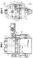
- a batch mixer designated as a whole has a horizontal mixing shaft 2, which is acted upon by a coaxial drive motor 3 and is accommodated in a drum-shaped housing 4 according to FIG. 2.
- the lower wall area of this housing 4 can be opened for drainage, two opening flaps 5 being pivotable to one another and away from one another like wings.
- These opening flaps 5 practically form the lower wall area of the housing 4. They are so large that the opening angle of the housing opening is larger than the slope angle of dry mix. 1, the opening flaps 5 run from the front to the front of the housing 4. In this way, complete emptying of a mixer is possible without additional cleaning measures, because when the opening flaps 5 are opened, the dry mix from the mixer, for example, initially falls into an intermediate funnel 6 can, without projections or the like. On which residues of mixed material could remain.
- the upper horizontal narrow valve sides 8 located in the joint area or in the region of the pivot axis 7 of the pivotable opening flap 5 are formed obliquely in cross-section, an acute angle being formed between the narrow side 8 and the outer side 9 of the opening flap 5, for example in can be of the order of 55 °.
- the housing opening has a matching counter bevel 10 as a contact surface for the sloping narrow flap side 8 when the opening flap 5 is closed, as shown in FIG. 3.
- a seal 11 which is operatively connected to the closed opening flap 5 is arranged.
- the seal 11 designed as a sealing strip could be embedded in the counter-bevel 10 of the mixer housing 4, so that the oblique narrow side 8 would contact the seal 11 in the closed position. With such an arrangement, the seal 11 is already on a “shadow side” in relation to the mixture flowing out.
- the sealing strip 11 is arranged on the outside of the housing 4 adjacent to the counter bevel 10 and is inserted into a groove 12 a and on the outside 9 of the opening flap 5 a pressure and counter strip 12 which overlaps this seal 11 in the closed position is attached.
- This counter bar 12 is detachable and exchangeable and also adjustable by means of screws 13. With this arrangement, the sealing strip 11 can practically not come into contact with the mix and be adversely affected by it, although it is arranged at a point where it could be very easily attached and, if necessary, also replaced.
- the counter bar 12 can not hinder the opening process of the opening flap 5, since the pivot axis 7 for this flap 5 is arranged outside the housing 4 and above the sealing joint formed by the inclined surfaces 8 and 10 on the one hand and the seal 11 and the counter bar 12.
- the surfaces lying against one another first detach before they are swiveled away from one another. Conversely, when they close, they lay against each other practically without mutual friction.
- the opening flaps also have sloping narrow sides 14 in their contact area and the opening flap 5, the sloping surface 14 of which forms an obtuse angle with the outside 9, has a sealing strip 11 in a region facing away from the mix, which cooperates with the other opening flap and its sealing surface.
- the sealing strip 11 is incorporated next to the inclined surface 14 of the flap 5 and the flap 5 with the acute-angled inclined surface 14 on its outside carries a counter strip 12 for application to the sealing strip 11, which in turn can be replaced by means of screws 13 and is also adjustable.
- This counter bar 12 in the contact area of the two opening flaps 5 can be exposed to a certain flow of material when the flaps are opened, so that they may be wears out faster, so it is advantageous if it can be replaced quickly.
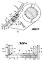
- the seal in the area of the end faces of the mixer 1 is illustrated particularly in FIG. 4.
- inclined surfaces 16 can be seen which form an acute angle with respect to the outside 17.
- the opening flaps also have an inclined surface 18 in this area, which runs at an acute angle to the outside thereof, the two inclined surfaces 16 and 18 matching each other in such a way that the closed opening flap 5 is mitred with this end wall region, as is the right part of the figure Fig. 4 illustrates.
- an outer housing wall section 19 is also provided, which projects downward beyond the flap end faces. This can pass into the funnel 6.
- Interchangeable counter strips, which bear against these sealing strips 20 in the closed position, can in turn be attached to the flap outer sides. In the right part of FIG. 4, these counter strips running parallel to the end faces are not visible, since they are covered by the longitudinal section through the counter strip 12 at the opening area of the two flaps. However, they can be connected directly to this sealing strip 12 on the end faces.
- sealing strips 11 and 20 are arranged and embedded around the very large housing opening at all points that are not touched by the outflowing material, which overlap with counter strips 12 on the flaps 5 in the closed position and under in their receiving groove 12 or 21 directional seal pressure. These sealing strips can also be replaced if they have aged or their sealing effect is weakening for other reasons. Elaborate labyrinth seals u. The like are avoided. This results in a mixer housing 4, which is dust-tight and maintains its tightness even at high pressures during the mixing process, but nevertheless has a very large outlet opening.
- the flap shape is adjustable, in particular in the area of the sealing strips 12 and 21 in the sense of a largely uniform sealing effect.
- stiffening arms 22 are arranged next to one another at a distance from the joint axis 7 over the length of the opening flaps 5. These are connected to the opening flaps 5 in a manner yet to be described and transmit the forces from working cylinders 23 to the flaps. these cylinders 23 according to FIG. 2 each engage with a lever arm 24 on the hinge axis 7.
- the stiffening arms 22 have fastening points for spacer plates 25 that can be used there.
- spacer plates 25 can be placed on the individual arms 22 in order to prevent deformations occurring during manufacture or under load to compensate for the opening flaps and to create a secure system everywhere, especially in the sealing area.
- the support arms 22 can have an angular or T-shaped cross-sectional profile, an angle leg or the T-crosspiece engaging the flap 5 and allowing the spacer plates 25 to be inserted between them and the flap.
- This is a very simple and functional design for bracing and adapting the flaps to high loads or to compensate for any deformations that may occur.
Landscapes
- Chemical & Material Sciences (AREA)
- Chemical Kinetics & Catalysis (AREA)
- Mixers Of The Rotary Stirring Type (AREA)
- Processing Of Solid Wastes (AREA)
- Accessories For Mixers (AREA)
- Processing And Handling Of Plastics And Other Materials For Molding In General (AREA)
- Transition And Organic Metals Composition Catalysts For Addition Polymerization (AREA)
- Preparation Of Clay, And Manufacture Of Mixtures Containing Clay Or Cement (AREA)
- Mixers With Rotating Receptacles And Mixers With Vibration Mechanisms (AREA)
Claims (16)
- Mélangeur discontinu (1), avec un carter (4) approximativement en forme de tambour et avec un arbre mélangeur (2) de préférence horizontal, la partie inférieure de la paroi du carter étant réalisée sous la forme d'au moins une trappe d'ouverture (5) destinée au vidage du mélangeur et pouvant pivoter autour d'un axe de pivotement (7), caractérisé en ce que l'angle d'ouverture est supérieur à l'angle de pente du produit mélangé et la trappe d'ouverture (5) s'étend d'un côté frontal du carter (4) à l'autre, en ce qu'au moins le côté étroit (8) de la trappe, à allure horizontale et situé dans la zone de l'axe de pivotement (7) de la trappe d'ouverture (5), présente en section une forme oblique et forme un angle aigu avec le côté extérieur (9) de la trappe d'ouverture (5), en ce que l'ouverture du carter présente une partie à oblicité inverse (10) correspondante, servant de butée pour le côté étroit oblique (8) de la trappe lorsque la trappe d'ouverture (5) est fermée, et en ce qu'un élément d'étanchéité (11, 20), qui coopère avec la trappe d'ouverture (5) fermée, est disposé contre le carter (4) au niveau de ce côté étroit (8), en un endroit opposé à l'intérieur du carter.
- Mélangeur selon la revendication 1, caractérisé en ce que la bordure d'étanchéité (11) est incorporée dans la partie à oblicité inverse (10) du carter de mélangeur (4).
- Mélangeur selon la revendication 1 ou 2, caractérisé en ce qu'une bordure d'étanchéité (11) est disposée sur ou incorporée dans le côté extérieur du carter (4) au voisinage de la partie à oblicité inverse (10), et en ce qu'une contre-bordure de pression (12) recouvrant cet élément d'étanchéité (11) à la position de fermeture est fixée sur le côté extérieur (9) de la trappe (5).
- Mélangeur selon la revendication 3, caractérisé en ce que la contre-bordure (12) est fixée de manière réglable et remplaçable sur le côté extérieur (9) de la trappe d'ouverture (5), et notamment de manière amovible.
- Mélangeur selon une des revendications 1 à 4, caractérisé en ce que l'axe de pivotement (7) pour la trappe d'ouverture (5) est disposé à l'extérieur du carter (4) et au-dessus du joint d'étanchéité.
- Mélangeur selon une des revendications précédentes, caractérisé en ce qu'il est prévu deux trappes d'ouverture (5) disposées sensiblement symétriquement, qui présentent dans leur zone de contact des côtés étroits obliques (14) qui s'appuient l'un contre l'autre à la position de fermeture.
- Mélangeur selon la revendication 6, caractérisé en ce que la trappe d'ouverture (5) dont la face oblique (4) forme un angle obtus avec le côté extérieur (9) posséde dans une zone opposée au produit mélangé une bordure d'étanchéité (11) qui coopère avec l'autre trappe d'ouverture (5) et sa face d'étanchéité.
- Mélangeur selon la revendication 6 ou 7, caractérisé en ce que la bordure d'étanchéité (11) est incorporée à côté de la face oblique (14) de la trappe d'ouverture (5) et en ce que la trappe d'ouverture (5) qui est munie du côté oblique (14) à angle aigu porte sur son côté extérieur (9) une contre-bordure (12), de préférence remplaçable, venant s'appuyer contre la bordure d'étanchéité.
- Mélangeur selon une des revendications 1 à 8, caractérisé en ce que les côtés étroits (18) reçoivent sur les côtés frontaux de la trappe une forme oblique en ceci qu'ils forment un angle aigu avec le côté extérieur (9) de la trappe (5), et que la paroi frontale (15) possède sur le carter du récipient une contre-surface (16) correspondante, un angle aigu étant prévu entre le côté extérieur et la surface oblique.
- Mélangeur selon la revendication 9, caractérisé en ce qu'il est prévu, à côté de la face d'appui (16) oblique prévue du côté frontal pour la trappe d'ouverture (5), une section extérieur de paroi de carter (19) qui dépasse vers le bas au-dessus du côté frontal de la trappe, et se raccorde de préférence à une trémie (6).
- Mélangeur selon la revendication 9 ou 10, caractérisé en ce qu'une bordure d'étanchéité (20) disposée dans le sens circonférentiel est fixée entre la face oblique (16) et la section extérieure de paroi de carter (19), et en ce que les trappes d'ouverture (5) possèdent sur leur côté extérieur des contre-bordures de préférence remplaçables, qui s'appuient contre ces bordures d'étanchéité (20) à la position de fermeture.
- Mélangeur selon une des revendications précédentes, caractérisé en ce que des bordures d'étanchéité (11, 20) sont disposées, et de préférence incorporées, circulairement autour de l'ouverture du carter en des points qui ne sont pas en contact avec le flux de produit, bordures qui, à la position de fermeture, sont recouvertes par des contre-bordures contre la ou les trappes d'ouverture (5), et sont soumises à une pression d'étanchéité dirigée dans leur rainure réceptrice (12a, 21) ou élément d'appui similaire.
- Mélangeur selon une des revendications 3 à 12, caractérisé en ce que tant les contre-bordures (12) que les éléments d'étanchéité (11, 20) sont incorporés ou serrés, le cas échéant dans des rainures (12a, 21), avec possibilité de remplacement.
- Mélangeur avec une ouverture de vidage s'étendant sur une grande partie de la circonférence et d'un côté frontal à l'autre, obturée par au moins une trappe, selon une des revendications précédentes, caractérisé en ce que la forme de la ou des trappes d'ouverture peut, notamment au niveau des éléments d'étanchéité ou autres éléments similaires, être réglée en vue d'obtenir pratiquement partout une action d'étanchéification uniforme.
- Mélangeur selon une des revendications 1 à 14, caractérisé en ce que des bras de renforcement (22) s'étendent à distance les uns à côté des autres sur la longueur de la trappe d'ouverture (5) depuis l'axe de pivotement (7), et présentent des points de fixation ou éléments similaires permettant de fixer entre eux et le côté extérieur (9) de la trappe d'ouverture (5) des éléments d'écartement qui pourront y être insérés, et notamment des tôles d'écartement (25).
- Mélangeur selon la revendication 15, caractérisé en ce que les bras de renforcement (22) destinés aux trappes d'ouverture (5) ont un profil de section en cornière ou en T, une branche de la cornière ou la branche transversale du T venant s'appuyer contre la trappe d'ouverture (5) et permettant d'insérer entre elle et la trappe d'ouverture (5) des éléments d'écartement, de préférence des tôles d'écartement (25).
Priority Applications (1)
| Application Number | Priority Date | Filing Date | Title |
|---|---|---|---|
| AT84111860T ATE26929T1 (de) | 1983-10-14 | 1984-10-04 | Chargenmischer. |
Applications Claiming Priority (2)
| Application Number | Priority Date | Filing Date | Title |
|---|---|---|---|
| DE19833337437 DE3337437A1 (de) | 1983-10-14 | 1983-10-14 | Chargenmischer |
| DE3337437 | 1983-10-14 |
Publications (4)
| Publication Number | Publication Date |
|---|---|
| EP0142003A2 EP0142003A2 (fr) | 1985-05-22 |
| EP0142003A3 EP0142003A3 (en) | 1985-08-14 |
| EP0142003B1 EP0142003B1 (fr) | 1987-05-06 |
| EP0142003B2 true EP0142003B2 (fr) | 1994-01-12 |
Family
ID=6211860
Family Applications (1)
| Application Number | Title | Priority Date | Filing Date |
|---|---|---|---|
| EP84111860A Expired - Lifetime EP0142003B2 (fr) | 1983-10-14 | 1984-10-04 | Mélangeur de charge |
Country Status (10)
| Country | Link |
|---|---|
| US (1) | US4572674A (fr) |
| EP (1) | EP0142003B2 (fr) |
| JP (1) | JPS6097033A (fr) |
| KR (2) | KR850003333A (fr) |
| AT (1) | ATE26929T1 (fr) |
| AU (1) | AU562893B2 (fr) |
| CA (1) | CA1225389A (fr) |
| DE (2) | DE3337437A1 (fr) |
| ES (1) | ES536650A0 (fr) |
| ZA (1) | ZA847708B (fr) |
Families Citing this family (17)
| Publication number | Priority date | Publication date | Assignee | Title |
|---|---|---|---|---|
| JPS62201625A (ja) * | 1986-02-28 | 1987-09-05 | Chichibu Eng Kk | 振動式2軸強制練りミキサ |
| DE4002099A1 (de) * | 1990-01-25 | 1991-08-01 | Draiswerke Gmbh | Mischer |
| CH689667A5 (de) * | 1994-04-29 | 1999-08-13 | Buehler Ag | Chargenmischer. |
| US5810475A (en) * | 1996-09-16 | 1998-09-22 | Brownwood Ross Company, Inc. | Single discharge door for continuous or batching operation of twin-shaft twin-trough mixers |
| DE29621448U1 (de) * | 1996-12-10 | 1997-02-06 | Liebherr-Mischtechnik Gmbh, 88427 Bad Schussenried | Verschluß |
| RU2133144C1 (ru) * | 1997-10-28 | 1999-07-20 | Муниципальное предприятие "РЕМСТРОЙБЛАГОУСТРОЙСТВО" | Перемешивающее устройство |
| DE29804378U1 (de) | 1998-03-12 | 1998-06-04 | m-tec mathis technik gmbh, 79395 Neuenburg | Schüttgutbehälter mit einer um eine Achse schwenkbaren Öffnungsklappe |
| DE19813867C2 (de) * | 1998-03-28 | 2000-03-23 | Loedige Maschbau Gmbh Geb | Vorrichtung zur Herstellung von Feststoff- und/oder Feststoff-Flüssigkeits-Mischungen |
| DE19957934A1 (de) * | 1999-12-01 | 2001-11-15 | Lehmann Maschb Gmbh | Chargenmischer mit Dosiervorrichtung |
| KR100734349B1 (ko) * | 2000-11-17 | 2007-07-03 | 엘지전자 주식회사 | 회전가능한 배플을 갖는 드럼세탁기 |
| EP1527811A1 (fr) * | 2003-10-30 | 2005-05-04 | WAM S.p.A. | Dispositif de mélange et transport pour poudres et pour mélanges de poudre et liquide |
| DE102004014834A1 (de) * | 2004-03-24 | 2005-10-13 | Elba-Werk Maschinen-Gesellschaft Mbh | Maschinenklappenbetätigung |
| CN100560194C (zh) * | 2005-10-28 | 2009-11-18 | 鸿富锦精密工业(深圳)有限公司 | 散热膏混合装置 |
| US7878700B2 (en) * | 2008-09-23 | 2011-02-01 | Equistar Chemicals, Lp | Polymer removal from a polymer mixer |
| US20110204611A1 (en) * | 2010-02-18 | 2011-08-25 | Daimler Trucks North America Llc | Fiber reinforced polymer frame rail |
| USD684811S1 (en) * | 2011-02-18 | 2013-06-25 | Buhler Ag | Batch mixer |
| CN106110999A (zh) * | 2016-08-02 | 2016-11-16 | 肇庆千江高新材料科技股份公司 | 一种免洗搅拌缸 |
Family Cites Families (13)
| Publication number | Priority date | Publication date | Assignee | Title |
|---|---|---|---|---|
| DE8226167U1 (de) * | 1982-12-16 | C. F. Maier GmbH & Co, 7923 Königsbronn | Großbehälter zum Sammeln von Altmaterial, insbesondere von Altpapier | |
| US3128901A (en) * | 1964-04-14 | Agnon | ||
| DE311116C (fr) * | ||||
| DE725208C (de) * | 1940-09-10 | 1942-09-17 | Buehler G M B H Geb | Tellerschleuse fuer Schuettgut |
| US2835269A (en) * | 1953-04-10 | 1958-05-20 | Smith Corp A O | Vessel closure |
| CH345593A (de) * | 1956-06-08 | 1960-03-31 | Theodor Kokeisl | Silo |
| CH349477A (de) * | 1957-02-28 | 1960-10-15 | Buehler Ag Geb | Chargenmischer |
| FR1329058A (fr) * | 1962-04-27 | 1963-06-07 | Bétonnière perfectionnée | |
| US3352542A (en) * | 1966-06-29 | 1967-11-14 | Stewart Bolling & Company Inc | Mixing machine |
| US4075713A (en) * | 1976-11-11 | 1978-02-21 | Easton Harlan J | Feed mixer |
| DE2903951C3 (de) * | 1979-02-02 | 1985-01-03 | Eirich, Hubert | Vorrichtung zum Verschließen einer Entleerungsöffnung in einem Behälterboden |
| US4462693A (en) * | 1980-01-25 | 1984-07-31 | Veda, Inc. | Material mixing apparatus |
| DE3236780C2 (de) * | 1982-10-05 | 1984-09-06 | Mathis System-Technik GmbH, 7844 Neuenburg | Misch- und Verladevorrichtung für Mischungen aus pulverigen und/oder körnigen Feststoffen |
-
1983
- 1983-10-14 DE DE19833337437 patent/DE3337437A1/de not_active Withdrawn
-
1984
- 1984-10-01 ZA ZA847708A patent/ZA847708B/xx unknown
- 1984-10-04 AT AT84111860T patent/ATE26929T1/de not_active IP Right Cessation
- 1984-10-04 EP EP84111860A patent/EP0142003B2/fr not_active Expired - Lifetime
- 1984-10-04 DE DE8484111860T patent/DE3463452D1/de not_active Expired
- 1984-10-10 ES ES536650A patent/ES536650A0/es active Granted
- 1984-10-11 AU AU34139/84A patent/AU562893B2/en not_active Ceased
- 1984-10-12 CA CA000465248A patent/CA1225389A/fr not_active Expired
- 1984-10-13 KR KR1019840006351A patent/KR850003333A/ko not_active Withdrawn
- 1984-10-15 US US06/661,111 patent/US4572674A/en not_active Expired - Fee Related
- 1984-10-15 JP JP59214453A patent/JPS6097033A/ja active Pending
-
1987
- 1987-06-26 KR KR2019870010294U patent/KR880000478Y1/ko not_active Expired
Also Published As
| Publication number | Publication date |
|---|---|
| CA1225389A (fr) | 1987-08-11 |
| JPS6097033A (ja) | 1985-05-30 |
| AU562893B2 (en) | 1987-06-18 |
| ES8603144A1 (es) | 1985-12-16 |
| ES536650A0 (es) | 1985-12-16 |
| US4572674A (en) | 1986-02-25 |
| AU3413984A (en) | 1985-04-18 |
| EP0142003A2 (fr) | 1985-05-22 |
| EP0142003B1 (fr) | 1987-05-06 |
| ZA847708B (en) | 1985-05-29 |
| DE3463452D1 (en) | 1987-06-11 |
| ATE26929T1 (de) | 1987-05-15 |
| KR880000478Y1 (ko) | 1988-03-12 |
| DE3337437A1 (de) | 1985-05-02 |
| KR850003333A (ko) | 1985-06-17 |
| EP0142003A3 (en) | 1985-08-14 |
Similar Documents
| Publication | Publication Date | Title |
|---|---|---|
| EP0142003B2 (fr) | Mélangeur de charge | |
| EP1859856B1 (fr) | Dispositif de mélange doté d'un compartiment à vide | |
| EP1140669A1 (fr) | Dispositif de dosage pour materiaux en vrac | |
| DE102019108869A1 (de) | Mischer mit Verschlussdeckel | |
| DE2601486B2 (de) | Anker für Deckel o.dgl. und Formrahmen | |
| DE3532796C2 (fr) | ||
| DE69102084T2 (de) | Schieberventil. | |
| DE1917029A1 (de) | Verschluss | |
| DE8816409U1 (de) | Zwei-Wege-Weiche für Schüttgut | |
| DE19813867C2 (de) | Vorrichtung zur Herstellung von Feststoff- und/oder Feststoff-Flüssigkeits-Mischungen | |
| EP0941947B1 (fr) | Récipient à produits en vrac avec porte d'ouverture à rabattre pivotante autour d'un axe | |
| DE2848437C3 (de) | Verstellbare Bandübergabe | |
| DE2403078C2 (de) | Behälter für Massengüter | |
| DE102016221066B4 (de) | Vorrichtung zur Herstellung einer Kautschukmischung | |
| DE2908778A1 (de) | Absperrorgan, insbesondere schieber | |
| EP2554082B1 (fr) | Séparation de douche | |
| DE2433107C3 (de) | Rundschieberverschluß für Entladungsfahrzeuge | |
| DE3911424A1 (de) | Zwei-wege-weiche fuer schuettgut | |
| DE1073693B (de) | Entleerungsvomchtung an einem Formsandmischer | |
| DE2902853B1 (de) | Rotationszellendosierer und -verschluss | |
| DE4121982C2 (de) | Trommelgleitschleifmaschine | |
| DE1509762C3 (de) | Deckelverschluß | |
| DE1077690B (de) | Rundschieberverschluss, insbesondere an Eisenbahn-Selbstentladern | |
| DE2063322A1 (de) | Verschlußbaugruppe fur den Auslaß von Schuttgutbehaltern | |
| DE2520263A1 (de) | Hinterschweisstasche, insbesondere fuer stahlzargen |
Legal Events
| Date | Code | Title | Description |
|---|---|---|---|
| PUAI | Public reference made under article 153(3) epc to a published international application that has entered the european phase |
Free format text: ORIGINAL CODE: 0009012 |
|
| AK | Designated contracting states |
Designated state(s): AT BE CH DE FR GB IT LI LU NL SE |
|
| PUAL | Search report despatched |
Free format text: ORIGINAL CODE: 0009013 |
|
| AK | Designated contracting states |
Designated state(s): AT BE CH DE FR GB IT LI LU NL SE |
|
| 17P | Request for examination filed |
Effective date: 19850725 |
|
| 17Q | First examination report despatched |
Effective date: 19860317 |
|
| RIN1 | Information on inventor provided before grant (corrected) |
Inventor name: MATHIS, BERNAHRD Inventor name: MATHIS, FRANZ Inventor name: ZIMMER, MAX Inventor name: MATHIS, PAUL |
|
| RAP1 | Party data changed (applicant data changed or rights of an application transferred) |
Owner name: M-TEC MATHIS TECHNIK GMBH |
|
| ITF | It: translation for a ep patent filed | ||
| GRAA | (expected) grant |
Free format text: ORIGINAL CODE: 0009210 |
|
| AK | Designated contracting states |
Kind code of ref document: B1 Designated state(s): AT BE CH DE FR GB IT LI LU NL SE |
|
| REF | Corresponds to: |
Ref document number: 26929 Country of ref document: AT Date of ref document: 19870515 Kind code of ref document: T |
|
| REF | Corresponds to: |
Ref document number: 3463452 Country of ref document: DE Date of ref document: 19870611 |
|
| ET | Fr: translation filed | ||
| PLBI | Opposition filed |
Free format text: ORIGINAL CODE: 0009260 |
|
| 26 | Opposition filed |
Opponent name: GEBR. LOEDIGE MASCHINENBAU-GESELLSCHAFT MBH Effective date: 19880205 Opponent name: BHS - BAYERISCHE BERG-, HUETTEN- UND SALZWERKE AG Effective date: 19880204 |
|
| NLR1 | Nl: opposition has been filed with the epo |
Opponent name: GEBR. LOEDIGE MASCHINENBAU-GESELLSCHAFT MBH Opponent name: BHS - BAYERISCHE BERG-, HUETTEN- UND SALZWERKE AG |
|
| PGFP | Annual fee paid to national office [announced via postgrant information from national office to epo] |
Ref country code: SE Payment date: 19910924 Year of fee payment: 8 |
|
| PGFP | Annual fee paid to national office [announced via postgrant information from national office to epo] |
Ref country code: CH Payment date: 19911004 Year of fee payment: 8 |
|
| PGFP | Annual fee paid to national office [announced via postgrant information from national office to epo] |
Ref country code: LU Payment date: 19911028 Year of fee payment: 8 |
|
| ITTA | It: last paid annual fee | ||
| PGFP | Annual fee paid to national office [announced via postgrant information from national office to epo] |
Ref country code: NL Payment date: 19911031 Year of fee payment: 8 Ref country code: AT Payment date: 19911031 Year of fee payment: 8 |
|
| PGFP | Annual fee paid to national office [announced via postgrant information from national office to epo] |
Ref country code: BE Payment date: 19911211 Year of fee payment: 8 |
|
| EPTA | Lu: last paid annual fee | ||
| PG25 | Lapsed in a contracting state [announced via postgrant information from national office to epo] |
Ref country code: LU Free format text: LAPSE BECAUSE OF NON-PAYMENT OF DUE FEES Effective date: 19921004 Ref country code: AT Effective date: 19921004 |
|
| PG25 | Lapsed in a contracting state [announced via postgrant information from national office to epo] |
Ref country code: SE Effective date: 19921005 |
|
| PG25 | Lapsed in a contracting state [announced via postgrant information from national office to epo] |
Ref country code: LI Effective date: 19921031 Ref country code: CH Effective date: 19921031 Ref country code: BE Effective date: 19921031 |
|
| BERE | Be: lapsed |
Owner name: M-TEC MATHIS TECHNIK G.M.B.H. Effective date: 19921031 |
|
| PG25 | Lapsed in a contracting state [announced via postgrant information from national office to epo] |
Ref country code: NL Effective date: 19930501 |
|
| NLV4 | Nl: lapsed or anulled due to non-payment of the annual fee | ||
| REG | Reference to a national code |
Ref country code: CH Ref legal event code: PL |
|
| ITF | It: translation for a ep patent filed | ||
| PUAH | Patent maintained in amended form |
Free format text: ORIGINAL CODE: 0009272 |
|
| STAA | Information on the status of an ep patent application or granted ep patent |
Free format text: STATUS: PATENT MAINTAINED AS AMENDED |
|
| 27A | Patent maintained in amended form |
Effective date: 19940112 |
|
| AK | Designated contracting states |
Kind code of ref document: B2 Designated state(s): AT BE CH DE FR GB IT LI LU NL SE |
|
| ET3 | Fr: translation filed ** decision concerning opposition | ||
| PGFP | Annual fee paid to national office [announced via postgrant information from national office to epo] |
Ref country code: GB Payment date: 19940930 Year of fee payment: 11 Ref country code: FR Payment date: 19940930 Year of fee payment: 11 |
|
| EUG | Se: european patent has lapsed |
Ref document number: 84111860.7 Effective date: 19930510 |
|
| PGFP | Annual fee paid to national office [announced via postgrant information from national office to epo] |
Ref country code: DE Payment date: 19950921 Year of fee payment: 12 |
|
| PG25 | Lapsed in a contracting state [announced via postgrant information from national office to epo] |
Ref country code: GB Effective date: 19951004 |
|
| GBPC | Gb: european patent ceased through non-payment of renewal fee |
Effective date: 19951004 |
|
| PG25 | Lapsed in a contracting state [announced via postgrant information from national office to epo] |
Ref country code: FR Effective date: 19960628 |
|
| REG | Reference to a national code |
Ref country code: FR Ref legal event code: ST |
|
| APAC | Appeal dossier modified |
Free format text: ORIGINAL CODE: EPIDOS NOAPO |
|
| APAC | Appeal dossier modified |
Free format text: ORIGINAL CODE: EPIDOS NOAPO |
|
| PG25 | Lapsed in a contracting state [announced via postgrant information from national office to epo] |
Ref country code: DE Effective date: 19970701 |
|
| APAH | Appeal reference modified |
Free format text: ORIGINAL CODE: EPIDOSCREFNO |