EP0142003B2 - Batch mixer - Google Patents
Batch mixer Download PDFInfo
- Publication number
- EP0142003B2 EP0142003B2 EP84111860A EP84111860A EP0142003B2 EP 0142003 B2 EP0142003 B2 EP 0142003B2 EP 84111860 A EP84111860 A EP 84111860A EP 84111860 A EP84111860 A EP 84111860A EP 0142003 B2 EP0142003 B2 EP 0142003B2
- Authority
- EP
- European Patent Office
- Prior art keywords
- opening
- flap
- mixer
- housing
- outside
- Prior art date
- Legal status (The legal status is an assumption and is not a legal conclusion. Google has not performed a legal analysis and makes no representation as to the accuracy of the status listed.)
- Expired - Lifetime
Links
- 238000007789 sealing Methods 0.000 claims abstract description 44
- 239000000463 material Substances 0.000 claims abstract description 18
- 125000006850 spacer group Chemical group 0.000 claims description 9
- 230000001154 acute effect Effects 0.000 claims description 8
- 230000013011 mating Effects 0.000 claims description 8
- 230000000694 effects Effects 0.000 claims description 6
- 238000012856 packing Methods 0.000 claims 14
- 230000002093 peripheral effect Effects 0.000 claims 1
- 230000000295 complement effect Effects 0.000 abstract description 2
- 230000009969 flowable effect Effects 0.000 abstract 1
- 239000011343 solid material Substances 0.000 abstract 1
- 239000000203 mixture Substances 0.000 description 26
- 238000004140 cleaning Methods 0.000 description 5
- 238000000034 method Methods 0.000 description 5
- 238000010276 construction Methods 0.000 description 4
- 238000004519 manufacturing process Methods 0.000 description 4
- 230000015572 biosynthetic process Effects 0.000 description 2
- 239000004570 mortar (masonry) Substances 0.000 description 2
- 230000002411 adverse Effects 0.000 description 1
- 239000013590 bulk material Substances 0.000 description 1
- 239000000470 constituent Substances 0.000 description 1
- 239000000428 dust Substances 0.000 description 1
- 230000003628 erosive effect Effects 0.000 description 1
- 230000002349 favourable effect Effects 0.000 description 1
- 230000001771 impaired effect Effects 0.000 description 1
- 230000036961 partial effect Effects 0.000 description 1
- 239000011505 plaster Substances 0.000 description 1
- 230000002829 reductive effect Effects 0.000 description 1
- 230000000717 retained effect Effects 0.000 description 1
- XLYOFNOQVPJJNP-UHFFFAOYSA-N water Substances O XLYOFNOQVPJJNP-UHFFFAOYSA-N 0.000 description 1
- 230000003313 weakening effect Effects 0.000 description 1
Images

Classifications
-
- B—PERFORMING OPERATIONS; TRANSPORTING
- B01—PHYSICAL OR CHEMICAL PROCESSES OR APPARATUS IN GENERAL
- B01F—MIXING, e.g. DISSOLVING, EMULSIFYING OR DISPERSING
- B01F35/00—Accessories for mixers; Auxiliary operations or auxiliary devices; Parts or details of general application
- B01F35/45—Closures or doors specially adapted for mixing receptacles; Operating mechanisms therefor
- B01F35/451—Closures or doors specially adapted for mixing receptacles; Operating mechanisms therefor by rotating them about an axis parallel to the plane of the opening
-
- B—PERFORMING OPERATIONS; TRANSPORTING
- B01—PHYSICAL OR CHEMICAL PROCESSES OR APPARATUS IN GENERAL
- B01F—MIXING, e.g. DISSOLVING, EMULSIFYING OR DISPERSING
- B01F27/00—Mixers with rotary stirring devices in fixed receptacles; Kneaders
- B01F27/60—Mixers with rotary stirring devices in fixed receptacles; Kneaders with stirrers rotating about a horizontal or inclined axis
Definitions
- the invention relates to a batch mixer with an approximately drum-shaped housing and preferably with a horizontal mixing shaft, the lower wall area of which is designed as at least one opening flap which can be pivoted about a pivot axis for emptying.
- Such a batch mixer is known from CH-A-349 477.
- the lower part of this batch mixer is designed as a folding door.
- the sealing of this folding door must be regarded as difficult and expensive due to its considerable size, but is not explained in this document.
- the opening angle of the opening closed by this folding door is greater than the angle of repose of the mixed material. Due to the size relationships that result from the drawing of this document, it is at most disclosed that the opening angle is smaller than the slope angle of dry mix, so that when emptying mix remains in the mixer housing and can only be removed by additional measures.
- EP-A-0 105 107 (filing date: July 20, 1983; priority October 5, 1982; publication date: April 11, 1984) describes a mixing device to which a batch mixer of the type mentioned at the beginning belongs, in which the opening angle is greater than the slope angle of the mix and the opening flap extends from the front to the front of the housing.
- the batch mixer provided here has the considerable advantage, particularly with regard to its emptying, that cleaning after emptying the material to be mixed is not necessary. This is achieved by the angle of repose of dry bulk material which exceeds the large opening angle, because no mixture can remain within the open housing of this mixer. A different mixture can be processed than the closing of the opening in the mixer without this previous mixture being impaired or influenced.
- FR-A-1 329 058 also discloses a drum-shaped mixer with a polygonal cross section of the mixer housing and two jaw-shaped slide valves which can be opened in the form of a jaw, the entire mixer housing being rotated during the mixing process. It is a concrete mixing machine with which a mix is to be mixed with water, so that a material-specific slope angle is irrelevant. Furthermore, the problem that mixtures of different compositions should be able to be produced in succession plays no role. without a previous mixture falsifying the next one in its composition.
- Batch mixers for dry goods have a relatively high internal pressure, especially if the mixer is of a suitable size for good performance. Numerous batch mixers are therefore also known from practice which have only relatively small openings so that they are not subjected to correspondingly high forces. Even then, residue-free emptying is not possible without additional cleaning measures.
- the batch mixer of the type mentioned with a lower openable wall area is characterized in that the opening angle is greater than the angle of repose of the material to be mixed and the opening flap extends from face to face of the housing, that at least that located in the region of the pivot axis of the opening flap , horizontally extending narrow side of the flap is oblique in cross-section and encloses an acute angle between itself and the outside of the opening flap, that the housing opening has a matching counter slope as an attachment for the sloping narrow side of the flap when the opening flap is closed and that in the area of this narrow side on the housing at one of the A seal that is operatively connected to the closed opening flap is arranged inside the housing.
- the oblique design of the upper horizontal narrow side of the opening flap ensures that when opening the flap this narrow side does not get into a horizontal, but rather a corresponding oblique position, so that no material can remain on it, which prevents the tight fitting when the flap is closed could.
- such an inclined joint has a better sealing effect overall, which is further improved and supported by the sealing strip.
- sealing strip is embedded in the counter-bevel of the mixer housing, so that the oblique narrow side of the opening flap directly contacts this seal in the closed position.
- a particularly favorable embodiment of the invention in which a seal can also be achieved if the inclined surface on the narrow side of the flap should be worn out by draining material, can consist of being adjacent on the outside of the housing to the counter slope, the sealing strip is arranged or embedded, and a pressure and counter strip that engages over this seal in the closed position is attached to the outside of the flap.
- a corresponding sealing strip in particular, to be embedded in a groove both on the oblique narrow side and on the outside of the housing.
- the sealing strip is located opposite the mix on a "shadow side" of the housing, so that it is not acted upon by the mix when it is discharged.
- the counter bar can be exchangeably and adjustably attached, in particular releasably, to the outside of the flap. This counter bar does not hinder the opening process if the pivot axis for the flap is arranged outside the housing and above the sealing joint. During the pivoting movement, the surfaces lying against one another then detach from one another before they are also pivoted away from one another. Conversely, when they close, they rest against each other practically without mutual friction.
- sealing strip is incorporated next to the inclined surface of the flap and the flap with the acute-angled bevel on the outside preferably carries a mating strip for engaging the sealing strip.
- this counter bar is exposed to a certain material closure when the flap is opened, so that it is advantageous if it can be replaced.
- the narrow sides of the flap can in turn be formed obliquely in such a way that the outside of the flap forms an acute angle with the narrow side, and on the container housing, the end wall can have a matching oblique counter surface all around on the circumference, which is pointed between the outside and the oblique surface Angle.
- an outer housing wall section can also be provided, which projects downward beyond the flap end face. This stabilizes the entire housing in this area.
- a sealing strip arranged in the circumferential direction can be fastened between the inclined surface and the outer housing wall, and the flaps can preferably have interchangeable counter strips on their outer sides, which in the closed position bear against these sealing strips running in the circumferential direction.
- sealing strips are arranged around the housing opening in places that are not touched by the outflowing material, preferably embedded, which are overlapped by counter strips on the flap (s) in the closed position and below in their receiving groove or the like seat directed sealing pressure are set.
- the seals can also be interchangeably clamped in grooves.
- the flap shape can be adjusted, in particular in the area of the sealing strips, in the sense of a largely uniform sealing effect. This can compensate for the loads on the flap, which could lead to loosening of the seal seat in certain areas.
- stiffening arms are arranged next to one another along the length of the flap along the length of the flap and have fastening points between them and the outside of the flap for spacer plates that can be used there.
- more or less spacer plates can be placed on the individual arms in order to have a secure system everywhere, even with heavy loads or deformation.
- the support arms for the flap have an angular or T-shaped cross-sectional profile, with an angle leg or the T-crosspiece engaging the flap and allowing the spacer plates to be inserted between them and the flap.
- a batch mixer designated as a whole has a horizontal mixing shaft 2, which is acted upon by a coaxial drive motor 3 and is accommodated in a drum-shaped housing 4 according to FIG. 2.
- the lower wall area of this housing 4 can be opened for drainage, two opening flaps 5 being pivotable to one another and away from one another like wings.
- These opening flaps 5 practically form the lower wall area of the housing 4. They are so large that the opening angle of the housing opening is larger than the slope angle of dry mix. 1, the opening flaps 5 run from the front to the front of the housing 4. In this way, complete emptying of a mixer is possible without additional cleaning measures, because when the opening flaps 5 are opened, the dry mix from the mixer, for example, initially falls into an intermediate funnel 6 can, without projections or the like. On which residues of mixed material could remain.
- the upper horizontal narrow valve sides 8 located in the joint area or in the region of the pivot axis 7 of the pivotable opening flap 5 are formed obliquely in cross-section, an acute angle being formed between the narrow side 8 and the outer side 9 of the opening flap 5, for example in can be of the order of 55 °.
- the housing opening has a matching counter bevel 10 as a contact surface for the sloping narrow flap side 8 when the opening flap 5 is closed, as shown in FIG. 3.
- a seal 11 which is operatively connected to the closed opening flap 5 is arranged.
- the seal 11 designed as a sealing strip could be embedded in the counter-bevel 10 of the mixer housing 4, so that the oblique narrow side 8 would contact the seal 11 in the closed position. With such an arrangement, the seal 11 is already on a “shadow side” in relation to the mixture flowing out.
- the sealing strip 11 is arranged on the outside of the housing 4 adjacent to the counter bevel 10 and is inserted into a groove 12 a and on the outside 9 of the opening flap 5 a pressure and counter strip 12 which overlaps this seal 11 in the closed position is attached.
- This counter bar 12 is detachable and exchangeable and also adjustable by means of screws 13. With this arrangement, the sealing strip 11 can practically not come into contact with the mix and be adversely affected by it, although it is arranged at a point where it could be very easily attached and, if necessary, also replaced.
- the counter bar 12 can not hinder the opening process of the opening flap 5, since the pivot axis 7 for this flap 5 is arranged outside the housing 4 and above the sealing joint formed by the inclined surfaces 8 and 10 on the one hand and the seal 11 and the counter bar 12.
- the surfaces lying against one another first detach before they are swiveled away from one another. Conversely, when they close, they lay against each other practically without mutual friction.
- the opening flaps also have sloping narrow sides 14 in their contact area and the opening flap 5, the sloping surface 14 of which forms an obtuse angle with the outside 9, has a sealing strip 11 in a region facing away from the mix, which cooperates with the other opening flap and its sealing surface.
- the sealing strip 11 is incorporated next to the inclined surface 14 of the flap 5 and the flap 5 with the acute-angled inclined surface 14 on its outside carries a counter strip 12 for application to the sealing strip 11, which in turn can be replaced by means of screws 13 and is also adjustable.
- This counter bar 12 in the contact area of the two opening flaps 5 can be exposed to a certain flow of material when the flaps are opened, so that they may be wears out faster, so it is advantageous if it can be replaced quickly.
- the seal in the area of the end faces of the mixer 1 is illustrated particularly in FIG. 4.
- inclined surfaces 16 can be seen which form an acute angle with respect to the outside 17.
- the opening flaps also have an inclined surface 18 in this area, which runs at an acute angle to the outside thereof, the two inclined surfaces 16 and 18 matching each other in such a way that the closed opening flap 5 is mitred with this end wall region, as is the right part of the figure Fig. 4 illustrates.
- an outer housing wall section 19 is also provided, which projects downward beyond the flap end faces. This can pass into the funnel 6.
- Interchangeable counter strips, which bear against these sealing strips 20 in the closed position, can in turn be attached to the flap outer sides. In the right part of FIG. 4, these counter strips running parallel to the end faces are not visible, since they are covered by the longitudinal section through the counter strip 12 at the opening area of the two flaps. However, they can be connected directly to this sealing strip 12 on the end faces.
- sealing strips 11 and 20 are arranged and embedded around the very large housing opening at all points that are not touched by the outflowing material, which overlap with counter strips 12 on the flaps 5 in the closed position and under in their receiving groove 12 or 21 directional seal pressure. These sealing strips can also be replaced if they have aged or their sealing effect is weakening for other reasons. Elaborate labyrinth seals u. The like are avoided. This results in a mixer housing 4, which is dust-tight and maintains its tightness even at high pressures during the mixing process, but nevertheless has a very large outlet opening.
- the flap shape is adjustable, in particular in the area of the sealing strips 12 and 21 in the sense of a largely uniform sealing effect.
- stiffening arms 22 are arranged next to one another at a distance from the joint axis 7 over the length of the opening flaps 5. These are connected to the opening flaps 5 in a manner yet to be described and transmit the forces from working cylinders 23 to the flaps. these cylinders 23 according to FIG. 2 each engage with a lever arm 24 on the hinge axis 7.
- the stiffening arms 22 have fastening points for spacer plates 25 that can be used there.
- spacer plates 25 can be placed on the individual arms 22 in order to prevent deformations occurring during manufacture or under load to compensate for the opening flaps and to create a secure system everywhere, especially in the sealing area.
- the support arms 22 can have an angular or T-shaped cross-sectional profile, an angle leg or the T-crosspiece engaging the flap 5 and allowing the spacer plates 25 to be inserted between them and the flap.
- This is a very simple and functional design for bracing and adapting the flaps to high loads or to compensate for any deformations that may occur.
Landscapes
- Chemical & Material Sciences (AREA)
- Chemical Kinetics & Catalysis (AREA)
- Mixers Of The Rotary Stirring Type (AREA)
- Processing Of Solid Wastes (AREA)
- Accessories For Mixers (AREA)
- Processing And Handling Of Plastics And Other Materials For Molding In General (AREA)
- Transition And Organic Metals Composition Catalysts For Addition Polymerization (AREA)
- Preparation Of Clay, And Manufacture Of Mixtures Containing Clay Or Cement (AREA)
- Mixers With Rotating Receptacles And Mixers With Vibration Mechanisms (AREA)
Abstract
Description
Die Erfindung betrifft einen Chargenmischer mit etwa trommelförmigem Gehäuse und mit vorzugsweise horizontaler Mischwelle, dessen unterer Wandungsbereich als wenigstens eine um eine Schwenkachse schwenkbare Öffnungsklappe für die Entleerung ausgebildet ist.The invention relates to a batch mixer with an approximately drum-shaped housing and preferably with a horizontal mixing shaft, the lower wall area of which is designed as at least one opening flap which can be pivoted about a pivot axis for emptying.
Eine derartiger Chargenmischer ist durch die CH-A-349 477 bekannt. Dabei ist der untere Teil dieses Chargenmischers als Klapptüre ausgebildet. Die Abdichtung dieser Klapptüre muß jedoch aufgrund ihrer erheblichen Größe als schwierig und aufwendig angesehen werden, wird jedoch in dieser Druckschrift nicht erläutert. Darüberhinaus ist nicht angegeben, daß der Öffnungswinkel der von dieser Klapptüre verschlossenen Öffnung größer als der Böschungswinkel des Mischgutes ist. Aufgrund der Größenverhältnisse, die sich aus der Zeichnung dieser Druckschrift ergeben, ist allenfalls offenbart, daß der Öffnungswinkel kleiner als der Böschungswinkel von trockenem Mischgut ist, so daß beim Entleeren Mischgut in dem Mischergehäuse liegen bleibt und nur durch zusätzliche Maßnahmen entfernt werden kann.Such a batch mixer is known from CH-A-349 477. The lower part of this batch mixer is designed as a folding door. However, the sealing of this folding door must be regarded as difficult and expensive due to its considerable size, but is not explained in this document. Furthermore, it is not specified that the opening angle of the opening closed by this folding door is greater than the angle of repose of the mixed material. Due to the size relationships that result from the drawing of this document, it is at most disclosed that the opening angle is smaller than the slope angle of dry mix, so that when emptying mix remains in the mixer housing and can only be removed by additional measures.
In der EP-A-0 105 107 (Anmeldetag : 20.07.1983; Priorität 05.10.1982; Veröffentlichungstag : 11.04.1984) ist eine Mischvorrichtung beschrieben, zu der ein Chargenmischer der eingangs erwähnten Art gehört, bei welchem der Öffnungswinkel größer als der Böschungswinkel des Mischgutes ist und die Öffnungsklappe von Stirnseite zu Stirnseite des Gehäuses reicht. Dabei handelt es sich zwar um eine ältere, jedoch nachveröffentlichte Druckschrift. Der dabei vorgesehene Chargenmischer hat vor allem bezüglich seiner Entleerung den erheblichen Vorteil, daß eine Reinigung nach der Entleerung des Mischgutes nicht erforderlich ist. Dies wird durch den Böschungswinkel von trockenem Schüttgut übertreffenden großen Öffnungswinkel erreicht, weil sich kein Mischgut innerhalb des geöffneten Gehäuses dieses Mischers halten kann. Es kann als noch dem Schließen der Öffnung in den Mischer eine andere Mischung bearbeitet werden, ohne daß diese vorausgegangene Mischung beeinträchtigt oder beeinflußt wird.EP-A-0 105 107 (filing date: July 20, 1983; priority October 5, 1982; publication date: April 11, 1984) describes a mixing device to which a batch mixer of the type mentioned at the beginning belongs, in which the opening angle is greater than the slope angle of the mix and the opening flap extends from the front to the front of the housing. This is an older, but later published publication. The batch mixer provided here has the considerable advantage, particularly with regard to its emptying, that cleaning after emptying the material to be mixed is not necessary. This is achieved by the angle of repose of dry bulk material which exceeds the large opening angle, because no mixture can remain within the open housing of this mixer. A different mixture can be processed than the closing of the opening in the mixer without this previous mixture being impaired or influenced.
Aus der FR-A-1 329 058 ist außerdem ein trommelförmiger Mischer mit polygonalem Querschnitt des Mischergehäuses und zwei maulförmig öffenbaren Muschelschiebern bekannt, wobei das gesamte Mischergehäuse während des Mischvorganges gedreht wird. Dabei handelt es sich um eine Betonmischmaschine, mit welcher ein Mischgut mit Wasser angemacht werden soll, so daß ein materialspezifischer Böschungswinkel keine Rolle spielt. Ferner spielt dabei das Problem keine Rolle, daß nacheinander Mischungen unterschiedlicher Zusammensetzungen hergestellt werden können sollen. ohne daß eine vorangegangene Mischung die nächstfolgende in ihrer Zusammensetzung verfälscht.FR-A-1 329 058 also discloses a drum-shaped mixer with a polygonal cross section of the mixer housing and two jaw-shaped slide valves which can be opened in the form of a jaw, the entire mixer housing being rotated during the mixing process. It is a concrete mixing machine with which a mix is to be mixed with water, so that a material-specific slope angle is irrelevant. Furthermore, the problem that mixtures of different compositions should be able to be produced in succession plays no role. without a previous mixture falsifying the next one in its composition.
Bei Chargenmischern für trockenes Gut entsteht ein relativ hoher Innendruck, insbesondere dann, wenn der Mischer für eine gute Leistung einen entsprechende Größe hat. Es sind deshalb außerdem zahlreiche Chargenmischer aus der Praxis bekannt, die nur relativ kleine Öffnungen haben, damit diese nicht entsprechend hohen Kräften ausgesetzt sind. Auch dann ist jedoch eine rückstandfreie Entleerung ohne zusätzliche Reinigungsmaßnahmen nicht möglich.Batch mixers for dry goods have a relatively high internal pressure, especially if the mixer is of a suitable size for good performance. Numerous batch mixers are therefore also known from practice which have only relatively small openings so that they are not subjected to correspondingly high forces. Even then, residue-free emptying is not possible without additional cleaning measures.
Es besteht deshalb die Aufgabe, einen Chargenmischer der eingangs erwähnten Art zu schaffen, bei welchem trotz hoher Kräfte in seinem Inneren eine derart große Öffnung möglich ist, daß durch das Öffnen eine rückstandfreie Entleerung ohne zusätzliche Reinigungsmaßnahmen möglich ist, wobei die große Öffnung sicher abgedichtet und verschlossen werden können soll und eine möglichst lange Lebensdauer erzielt werden soll.There is therefore the task of creating a batch mixer of the type mentioned, in which, despite high forces, such a large opening is possible in its interior that residue-free emptying is possible without additional cleaning measures, the large opening being securely sealed and should be able to be closed and the longest possible service life should be achieved.
Zur Lösung dieser Aufgabe ist der Chargenmischer der eingangs erwähnten Art mit einem unteren öffenbaren Wandbereich dadurch gekennzeichnet, daß der Öffnungswinkel größer als der Böschungswinkel des Mischgutes ist und die Öffnungsklappe von Stirnseite zu Stirnseite des Gehäuses reicht, daß zumindest die im Bereich der Schwenkachse der Öffnungsklappe befindliche, horizontal verlaufende Klappenschmalseite im Querschnitt schräg ausgebildet ist und zwischen sich und der Außenseite der Öffnungsklappe einen spitzen Winkel einschließt, daß die Gehäuseöffnung eine dazu passende Gegenschräge als Anlage für die schräge Klappenschmalseite bei geschlossener Öffnungsklappe hat und daß im Bereich dieser Schmalseite am Gehäuse an einer dem Gehäuseinneren abgewandten Stelle eine mit der geschlossenen Öffnungsklappe in Wirkverbindung stehende Dichtung angeordnet ist.To solve this problem, the batch mixer of the type mentioned with a lower openable wall area is characterized in that the opening angle is greater than the angle of repose of the material to be mixed and the opening flap extends from face to face of the housing, that at least that located in the region of the pivot axis of the opening flap , horizontally extending narrow side of the flap is oblique in cross-section and encloses an acute angle between itself and the outside of the opening flap, that the housing opening has a matching counter slope as an attachment for the sloping narrow side of the flap when the opening flap is closed and that in the area of this narrow side on the housing at one of the A seal that is operatively connected to the closed opening flap is arranged inside the housing.
Durch die schräge Ausbildung der oberen horizontalen Schmalseite der Öffnungsklappe wird erreicht, daß beim Öffnen der Klappe diese Schmalseite nicht in eine horizontale, sondern eine entsprechende schräge Lage gelangt, so daß kein Material darauf liegen bleiben kann, welches beim Schließen der Klappe das dichte Anlegen verhindern könnte. Darüber hinaus hat eine solche schräge Fuge insgesamt eine bessere Dichtwirkung, die durch die Dichtungsleiste noch verbessert und unterstützt wird.The oblique design of the upper horizontal narrow side of the opening flap ensures that when opening the flap this narrow side does not get into a horizontal, but rather a corresponding oblique position, so that no material can remain on it, which prevents the tight fitting when the flap is closed could. In addition, such an inclined joint has a better sealing effect overall, which is further improved and supported by the sealing strip.
Dabei ist es möglich, daß die Dichtleiste in die Gegenschräge des Mischergehäuses eingelassen ist, so daß sich die schräge Schmalseite der Öffnungsklappe in Schließstellung an diese Dichtung unmittelbar anlegt.It is possible that the sealing strip is embedded in the counter-bevel of the mixer housing, so that the oblique narrow side of the opening flap directly contacts this seal in the closed position.
Eine besonders günstige Ausgestaltung der Erfindung, bei der auch noch eine Abdichtung erzielt werden kann, wenn die Schrägfläche an der Klappenschmalseite durch abfließendes Material verschlissen sein sollte, kann darin bestehen, daß an der Außenseite des Gehäuses benachbart zu der Gegenschräge die Dichtleiste angeordnet oder eingelassen ist und an der Außenseite der Klappe eine diese Dichtung in Schließstellung übergreifende Andruck- und Gegenleiste befestigt ist.A particularly favorable embodiment of the invention, in which a seal can also be achieved if the inclined surface on the narrow side of the flap should be worn out by draining material, can consist of being adjacent on the outside of the housing to the counter slope, the sealing strip is arranged or embedded, and a pressure and counter strip that engages over this seal in the closed position is attached to the outside of the flap.
Ferner ist es natürlich auch möglich, daß sowohl an der schrägen Schmalseite als auch an der Gehäuseaußenseite jeweils eine entsprechende Dichtungsleiste insbesondere in eine Nut eingelassen ist. In jedem Falle befindet sich die Dichtungsleiste gegenüber dem Mischgut auf einer « Schattenseite » des Gehäuses, so daß sie beim Ablassen des Mischgutes von diesem nicht beaufschlagt wird. Gegenüber Labyrinthdichtungen im Fugenbereich ergibt sich der Vorteil einer wesentlich einfacheren Herstellung bei dennoch guter Dichtwirkung, die auch durch einen gewissen Verschleiß nicht vermindert wird.Furthermore, it is of course also possible for a corresponding sealing strip, in particular, to be embedded in a groove both on the oblique narrow side and on the outside of the housing. In any case, the sealing strip is located opposite the mix on a "shadow side" of the housing, so that it is not acted upon by the mix when it is discharged. Compared to labyrinth seals in the joint area, there is the advantage of a much simpler production with a good sealing effect, which is not reduced by a certain amount of wear.
Die Gegenleiste kann an der Außenseite der Klappe auswechselbar und einstellbar insbesondere lösbar befestigt sein. Dabei behindert diese Gegenleiste den Öffnungsvorgang nicht, wenn die Schwenkachse für die Klappe außerhalb des Gehäuses und oberhalb der Dichtungsfuge angeordnet ist. Bei der Schwenkbewegung lösen sich dann die aneinanderliegenden Flächen zunächst voneinander ab, bevor sie auch voneinander weggeschwenkt werden. Umgekehrt legen sie sich beim Schließen wieder praktisch ohne gegenseitige Reibung aneinander an.The counter bar can be exchangeably and adjustably attached, in particular releasably, to the outside of the flap. This counter bar does not hinder the opening process if the pivot axis for the flap is arranged outside the housing and above the sealing joint. During the pivoting movement, the surfaces lying against one another then detach from one another before they are also pivoted away from one another. Conversely, when they close, they rest against each other practically without mutual friction.
Da eine sehr große Öffnung des Mischergehäuses staubdicht geschlossen gehalten werden muß, ist es besonders vorteilhaft, wenn zwei etwa symmetrisch angeordnete Klappen vorgesehen sind, die in ihrem Berührungsbereich schräge Schmalseiten haben, die in Schließstellung aneinanderliegen. Dabei kann wiederum an der Klappe, deren Schrägfläche mit der Außenseite einen stumpfen Winkel bildet, eine Dichtleiste in einem dem Materialschluß abgewandten Bereich haben, welche mit der anderen Klappe und deren Dichtfläche zusammenwirkt.Since a very large opening of the mixer housing must be kept closed in a dust-tight manner, it is particularly advantageous if two approximately symmetrically arranged flaps are provided which have sloping narrow sides in their contact area which abut one another in the closed position. Again, on the flap, the inclined surface of which forms an obtuse angle with the outside, a sealing strip in an area facing away from the material closure, which cooperates with the other flap and its sealing surface.
Dabei ist es auch bei einer solchen Ausführungsform mit zwei sich flügelartig schließenden Klappen besonders zweckmäßig, wenn die Dlchtleiste neben der Schrägfläche der Klappe eingearbeitet ist und die Klappe mit der spitzwinkligen Schräge an ihrer Außenseite eine Gegenleiste zum Anliegen an der Dichtleiste vorzugsweise auswechselbar trägt. Vor allem diese Gegenleiste ist beim Öffnen der Klappe einem gewissen Materialschluß ausgesetzt, so daß es vorteilhaft ist, wenn sie ausgewechselt werden kann.It is also particularly expedient in such an embodiment with two wing-like flaps if the sealing strip is incorporated next to the inclined surface of the flap and the flap with the acute-angled bevel on the outside preferably carries a mating strip for engaging the sealing strip. Especially this counter bar is exposed to a certain material closure when the flap is opened, so that it is advantageous if it can be replaced.
An den Klappenstirnseiten können deren Schmalseiten wiederum schräg in der Weise ausgebildet sein, daß die Außenseite der Klappe mit der Schmalseite einen spitzen Winkel bildet, und am Behältergehäuse kann die Stirnwand am Umfang umlaufend eine dazu passende schräge Gegenfläche haben, die zwischen Außenseite und Schrägfläche einen spitzen Winkel hat. Bei geschlossenen Klappen liegen diese also an diesen Stirnwänden im Querschnitt auf Gehrung aneinander.On the flap end faces, the narrow sides of the flap can in turn be formed obliquely in such a way that the outside of the flap forms an acute angle with the narrow side, and on the container housing, the end wall can have a matching oblique counter surface all around on the circumference, which is pointed between the outside and the oblique surface Angle. When the flaps are closed, they are miter-jointed on these end walls.
Neben den stirnseitigen schrägen Anlageflächen für die Klappen kann außerdem noch ein äußerer Gehäusewandabschnitt vorgesehen sein, der über die Klappenstirnseite nach unten vorsteht. Dadurch wird das gesamte Gehäuse in diesem Bereich stabilisiert.In addition to the oblique contact surfaces for the flaps on the end face, an outer housing wall section can also be provided, which projects downward beyond the flap end face. This stabilizes the entire housing in this area.
Ferner kann zwischen der Schrägfläche und der äußeren Gehäusewandung eine in Umfangsrichtung angeordnete Dichtleiste befestigt sein und die Klappen können an ihren Außenseiten vorzugsweise auswechselbare Gegenleisten haben, die in Schließstellung gegen diese in Umfangsrichtung verlaufenden Dichtleisten anliegen.Furthermore, a sealing strip arranged in the circumferential direction can be fastened between the inclined surface and the outer housing wall, and the flaps can preferably have interchangeable counter strips on their outer sides, which in the closed position bear against these sealing strips running in the circumferential direction.
Es ergibt sich bei Kombination der vorbeschriebenen Merkmale und Maßnahmen also, daß rings um die Gehäuseöffnung an Stellen, die von dem ausfließenden Material nicht berührt werden, Dichtleisten angeordnet, vorzugsweise eingelassen sind, die von Gegenleisten an der/den Klappen in Schließstellung übergriffen und unter in ihre Aufnahmenut od. dgl. Sitz gerichteten Dichtungsdruck gesetzt sind. Dabei können außer den Gegenleisten an den Klappen auch die Dichtungen auswechselbar gegebenenfalls in Nuten eingeklemmt sein.It results from a combination of the features and measures described above that sealing strips are arranged around the housing opening in places that are not touched by the outflowing material, preferably embedded, which are overlapped by counter strips on the flap (s) in the closed position and below in their receiving groove or the like seat directed sealing pressure are set. In addition to the counter strips on the flaps, the seals can also be interchangeably clamped in grooves.
Vor allem die Kombination der schrägen Anlageflächen in allen Dichtungsbereichen, bei denen die Schrägungswinkel so gelegt sind, daß die Klappe von ihrer Innenseite nach außen in ihrer Abmessung größer wird, mit den Dichtungen und Dichtleisten ergibt eine sehr einfache Konstruktion, die auch das Öffnen und Schließen der Klappe in herkömmlicher Weise ohne zusätzliche Bewegungskomponenten erlaubt, wobei aber dennoch die Dichtungen gegen das stark erodierende Material geschützt sind, so daß die Abdichtung über lange Zeit erhalten bleibt.Above all, the combination of the inclined contact surfaces in all sealing areas, in which the helix angles are set so that the flap increases in size from the inside to the outside, with the seals and sealing strips results in a very simple construction, which also opens and closes the flap is allowed in a conventional manner without additional movement components, but the seals are nevertheless protected against the strongly eroding material, so that the seal is retained for a long time.
Als weitere Ausgestaltung ist es zweckmäßig, wenn die Klappenform insbesondere im Bereich der Dichtungsleisten im Sinne einer weitgehend überall gleichmäßigen Dichtwirkung einstellbar ist. Dadurch können die Belastungen auf die Klappe, die unter Umständen zu bereichsweisen Lockerungen des Dichtungssitzes führen könnten, ausgeglichen werden.As a further embodiment, it is expedient if the flap shape can be adjusted, in particular in the area of the sealing strips, in the sense of a largely uniform sealing effect. This can compensate for the loads on the flap, which could lead to loosening of the seal seat in certain areas.
Besonders zweckmäßig ist es dabei, wenn von den Klappengelenken über die Länge der Klappe nebeneinander mit Abstand angeordnete Aussteifungsarme angeordnet sind, die zwischen sich und der Klappenaußenseite Befestigungsstellen für dort einsetzbare Distanzbleche haben. Je nach Belastung und Verformung der Klappen können also an den einzelnen Armen mehr oder weniger Distanzbleche untergelegt werden, um überall eine sichere Anlage auch bei starker Belastung oder Verformung zu haben. Dabei ist es besonders vorteilhaft, wenn die Stützarme für die Klappe ein winkel- oder T-förmiges Querschnittsprofil haben, wobei ein Winkelschenkel oder der T-Quersteg an der Klappe angreift und zwischen sich und der Klappe das Einlegen der Distanzbleche erlaubt.It is particularly expedient if stiffening arms are arranged next to one another along the length of the flap along the length of the flap and have fastening points between them and the outside of the flap for spacer plates that can be used there. Depending on the load and deformation of the flaps, more or less spacer plates can be placed on the individual arms in order to have a secure system everywhere, even with heavy loads or deformation. It is particularly advantageous if the support arms for the flap have an angular or T-shaped cross-sectional profile, with an angle leg or the T-crosspiece engaging the flap and allowing the spacer plates to be inserted between them and the flap.
Trotz einer sehr großen Entleerungsöffnung ergibt sich eine einfache Konstruktion, die auch bei einem trockenen Mischgut mit staubförmigen Anteilen eine sicher Abdichtung selbst nach längerer Betriebszeit erlaubt. Dennoch ist die Konstruktion einfach und kann mit herkömmlichen Betätigungsmitteln wie z. B. Arbeitszylindern, die die Öffnungsklappen betätigen, arbeiten.Despite a very large emptying opening, there is a simple construction, which can also be used with a dry mix with dust Proportions a secure seal is allowed even after a long period of operation. Nevertheless, the construction is simple and can be done with conventional actuating means such. B. working cylinders that operate the opening flaps work.
Nachstehend ist die Erfindung mit ihren ihr als wesentlich zugehörenden Einzelheiten anhand der Zeichnung noch näher beschrieben. Es zeigt in zum Teil schematisierter Darstellung :
Figur 1 eine Seitenansicht undFigur 2 eine Stirnansicht eines erfindungsgemäßen Mischers,Figur 3 in vergrößertem Maßstab die Ausbildung der Dichtungsfuge zwischen einer Öffnungsklappe und dem Mischergehäuse im Bereich einer Schwenkachse,- Figur 4 einen Teil-Längsschnitt mit der Ausbildung der stirnseitigen Anlageflächen an den Öffnungsklappen und dem Gehäuse,
Figur 5 die Abdichtung zweier flügelartig angeordneter und sich ergänzender Öffnungsklappen im Querschnitt in Schließstellung.Figur 6 in Seitenansicht die Befestigung eines an der Schwenkachse einer Öffnungsklappe befestigten Stützarmes mit dieser Klappe und dazwischen befindlichen Distanzblechen sowieFigur 7 eine Seitenansicht zweier Stützarme gemäß Fig. 6 mit Schwenkachse und Öffnungsklappe.
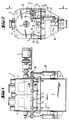
- Figure 1 is a side view
- FIG. 2 shows an end view of a mixer according to the invention,
- FIG. 3 shows, on an enlarged scale, the formation of the sealing joint between an opening flap and the mixer housing in the region of a pivot axis,
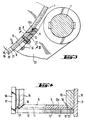
- FIG. 4 shows a partial longitudinal section with the formation of the end contact surfaces on the opening flaps and the housing,
- Figure 5 shows the seal of two wing-like and complementary opening flaps in cross section in the closed position.
- Figure 6 in side view of the attachment of a support arm attached to the pivot axis of an opening flap with this flap and spacer plates located in between and
- 7 shows a side view of two support arms according to FIG. 6 with pivot axis and opening flap.
Ein im ganzen mit 1 bezeichneter Chargenmischer hat eine horizontale Mischwelle 2, die von einem koaxialen Antriebsmotor 3 beaufschlagt ist und gemäß Fig. 2 in einem trommelförmigen Gehäuse 4 untergebracht ist. Dabei ist der untere Wandungsbereich dieses Gehäuses 4 für die Entleefung öffenbar, wobei zwei Öffnungsklappen 5 flügelartig zueinander und voneinander wegschwenkbar sind. Diese Öffnungsklappen 5 bilden praktisch den unteren Wandbereich des Gehäuses 4. Sie sind so groß ausgebildet, daß der Öffnungswinkel der Gehäuseöffnung größer als der Böschungswinkel von trockenem Mischgut ist. Gemäß Fig. 1 verlaufen dabei die Öffnungsklappen 5 von Stirnseite zu Stirnseite des Gehäuses 4. Auf diese Weise ist eine restlose Entleerung eines Mischers ohne zusätzliche Reinigungsmaßnahmen möglich, weil beim Öffnen der Öffnungsklappen 5 das trockene Mischgut aus dem Mischer beispielsweise zunächst in einen Zwischentrichter 6 fallen kann, ohne daß Vorsprünge od. dgl. vorhanden sind, auf denen Reste von Mischgut liegen bleiben könnten.A batch mixer designated as a whole has a
Um einerseits eine hohe Dichtigkeit, andererseits eine einfache und preiswerte Konstruktion zu erzielen und zu verhindern, daß auf den Schmalseiten der geöffneten Öffnungsklappen 5 Mischgut liegen bleibt. sind gemäß Fig. 3 die im Gelenkbereich bzw. im Bereich der Schwenkachse 7 der schwenkbaren Öffnungsklappe 5 befindlichen oberen horizontalen Klappenschmalseiten 8 im Querschnitt schräg ausgebildet, wobei zwischen der Schmalseite 8 und der Außenseite 9 der Öffnungsklappe 5 ein spitzer Winkel gebildet ist, der beispielsweise in der Größenordnung von 55° liegen kann. Die Gehäuseöffnung hat eine dazu passende Gegenschräge 10 als Anlagefläche für die schräge Klappenschmalseite 8 bei geschlossener Öffnungsklappe 5, wie es in Fig. 3 dargestellt ist. Darüber hinaus ist im Bereich dieser Schmalseite 8 am Gehäuse 4 an einer dem Gehäuseinneren abgewandten Stelle eine mit der geschlossenen Öffnungsklappe 5 in Wirkverbindung stehende Dichtung 11 angeordnet. Die als Dichtleiste ausgebildete Dichtung 11 könnte dabei in die Gegenschräge 10 des Mischergehäuses 4 eingelassen sein, so daß sich die schräge Schmalseite 8 in Schließstellung an die Dichtung 11 anlegen würde. Schon bei einer solchen Anordnung befindet sich die Dichtung 11 auf einer « Schattenseite » gegenüber ausfließendem Mischgut. Im Ausführungsbeispiel ist jedoch vorgesehen, daß an der Außenseite des Gehäuses 4 benachbart zu der Gegenschräge 10 die Dichtleiste 11 angeordnet und in eine Nut 12 a eingelassen ist und an der Außenseite 9 der Öffnungsklappe 5 eine diese Dichtung 11 in Schließstellung übergreifende Andrück- und Gegenleiste 12 befestigt ist. Diese Gegenleiste 12 ist mittels Schrauben 13 lösbar und auswechselbar sowie auch einstellbar befestigt. Durch Diese Anordnung kann die Dichtleiste 11 praktisch überhaupt nicht mit Mischgut in Berührung kommen und von diesem beeinträchtigt werden, obwohl sie an einer Stelle angeordnet ist, wo sie sehr einfach befestigt und gegebenenfalls auch ausgewechselt werden könnte.In order on the one hand to achieve a high level of tightness, on the other hand to achieve a simple and inexpensive construction and to prevent 5 mixed material from remaining on the narrow sides of the opened opening flaps. 3, the upper horizontal narrow valve sides 8 located in the joint area or in the region of the
Die Gegenleiste 12 kann dabei den Öffnungsvorgang der Öffnungsklappe 5 nicht behindern, da die Schwenkachse 7 für diese Klappe 5 außerhalb des Gehäuses 4 und oberhalb der von den Schrägflächen 8 und 10 einerseits sowie der Dichtung 11 und der Gegenleiste 12 gebildeten Dichtungsfuge angeordnet ist. Bei der Schwenkbewegung um die Achse 7 lösen sich die aneinanderliegenden Flächen zunächst, bevor sie auch voneinander weggeschwenkt werden. Umgekehrt legen sie sich beim Schließen praktisch ohne gegenseitige Reibungen wieder gegeneinander.The
In Fig. 5 ist der Berührungsbereich der beiden symmetrischen Öffnungsklappen 5 und die dort vorgesehene Abdichtung verdeutlicht. Dabei haben die Öffnungsklappen in ihrem Berührungsbereich ebenfalls schräge Schmalseiten 14 und die Öffnungsklappe 5, deren Schrägfläche 14 mit der Außenseite 9 einen stumpfen Winkel bildet, hat in einem dem Mischgut abgewandten Bereich eine Dichtleiste 11, welche mit der anderen Öffnungsklappe und deren Dichtfläche zusammenwirkt. Dabei ist auch in diesem Falle vorgesehen, daß die Dichtleiste 11 neben der Schrägfläche 14 der Klappe 5 eingearbeitet ist und die Klappe 5 mit der spitzwinkligen Schrägfläche 14 an ihrer Außenseite eine Gegenleiste 12 zum Anlegen an die Dichtleiste 11 trägt, die wiederum mittels Schrauben 13 auswechselbar und auch einstellbar befestigt ist. Diese Gegenleiste 12 im Berührungsbereich der beiden Öffnungsklappen 5 kann beim Öffnen der Klappen einem gewissen Materialfluß ausgesetzt sein, so daß sie gegebenenfalls schneller verschleißt, so daß es vorteilhaft ist, wenn sie schnell ausgewechselt werden kann.5 shows the contact area of the two symmetrical opening flaps 5 and the seal provided there. The opening flaps also have sloping
Vor allem in Fig. 4 ist die Abdichtung im Bereich der Stirnseiten des Mischers 1 verdeutlicht. Man erkennt an den Stirnwänden 15 wiederum Schrägflächen 16, die gegenüber der Außenseite 17 einen spitzen Winkel bilden. Auch die Öffnungsklappen haben in diesem Bereich eine Schrägfläche 18, die im spitzen Winkel zu ihrer Außenseite verläuft, wobei die beiden Schrägflächen 16 und 18 in der Weise zueinanderpassen, daß die geschlossene Öffnungsklappe 5 mit diesem Stirnwandbereich auf Gehrung aneinanderliegt, wie es der rechte Teil der Fig. 4 verdeutlicht.The seal in the area of the end faces of the
Neben diesen schrägen Anlageflächen 16 für die Öffnungsklappen 5 ist noch ein äußerer Gehäusewandabschnitt 19 vorgesehen, der über die Klappenstirnseiten nach unten vorsteht. Dieser kann in den Trichter 6 übergehen.In addition to these inclined contact surfaces 16 for the opening flaps 5, an outer
Zwischen den Schrägflächen 16 und der äußeren Gehäusewandung 19 ist eine in Umfangsrichtung gemäß der Wölbung der Öffnungsklappen 5 angeordnete Dichtleiste 20 befestigt, wobei diese Dichtleiste 20 in eine entsprechende Nut 21 eingelassen sein kann. An den Klappen-Außenseiten können wiederum auswechselbare Gegenleisten befestigt sein, die in Schließstellung gegen diese Dichtleisten 20 anliegen. In dem rechten Teil der Fig. 4 sind diese parallel zu den Stirnseiten verlaufende Gegenleisten nicht sichtbar, da sie vom Längsschnitt durch die Gegenleiste 12 am Öffnungsbereich der beiden Klappen verdeckt sind. Sie können jedoch an den Stirnseiten unmittelbar an diese Dichtleiste 12 angeschlossen sein.A sealing
Es ergibt sich also, daß rings um die sehr große Gehäuseöffnung an allen Stellen, die von ausfließendem Material nicht berührt werden, Dichtleisten 11 bzw. 20 angeordnet und eingelassen sind, die von Gegenleisten 12 an den Klappen 5 in Schließstellung übergriffen und unter in ihrer Aufnahmenut 12 bzw. 21 gerichtetem Dichtungsdruck stehen. Dabei können auch diese Dichtungsleisten ausgewechselt werden, falls sie gealtert sind oder aus sonstigen Gründen in ihrer Dichtwirkung nachlassen. Aufwendige Labyrinthdichtungen u. dgl. sind aber vermieden. Somit ergibt sich ein Mischergehäuse 4, welches staubdicht ist und auch bei hohen Drücken während des Mischvorganges seine Dichtigkeit behält, dennoch aber eine sehr große Auslaßöffnung hat.It follows that sealing strips 11 and 20 are arranged and embedded around the very large housing opening at all points that are not touched by the outflowing material, which overlap with counter strips 12 on the
Wegen der hohen Kräfte beim Mischvorgang und den daraus resultierenden, gegebenenfalls ungleichmäßigen Belastungen sowie der Großflächigkeit der Öffnungsklappen 5 ist im Ausführungsbeispiel ferner vorgesehen. daß die Klappenform insbesondere im Bereich der Dichtungsleisten 12 und 21 im Sinne einer weitgehend überall gleichmäßigen Dichtwirkung einstellbar ist. Man erkennt in Fig. 1, daß von der Gelenkachse 7 über die Länge der Öffnungsklappen 5 verteilt nebeneinander mit Abstand Aussteifungsarme 22 angeordnet sind. Diese sind mit den Öffnungsklappen 5 in noch zu beschreibender Weise verbunden und übertragen die Kräfte von Arbeitszylindern 23 auf die Klappen. wobei diese Zylinder 23 gemäß Fig. 2 jeweils mit einem Hebelarm 24 an der Gelenkachse 7 angreifen.Because of the high forces during the mixing process and the resulting, possibly uneven loads and the large area of the opening flaps 5 is also provided in the embodiment. that the flap shape is adjustable, in particular in the area of the sealing strips 12 and 21 in the sense of a largely uniform sealing effect. It can be seen in FIG. 1 that stiffening
Zwischen sich und der Klappenaußenseite 9 haben die Aussteifungsarme 22 Befestigungsstellen für dort einsetzbare Distanzbleche 25. Je nach Belastung und Verformung der Öffnungsklappen 5 können also an den einzelnen Armen 22 mehr oder weniger Distanzbleche 25 unterge legt werden, um bei der Herstellung oder unter Belastung auftretende Verformungen der Öffnungsklappen auszugleichen und überall eine sichere Anlage insbesondere im Dichtungsbereich zu bewirken.Between themselves and the flap outside 9, the stiffening
Gemäß den Figuren 6 und 7 können dabei die Stützarme 22 ein winkel- oder T-förmiges Querschnittsprofil haben, wobei ein Winkelschenkel oder der T-Quersteg an der Klappe 5 angreift und zwischen sich und der Klappe das Einlegen der Distanzbleche 25 erlaubt. Dies ist eine sehr einfache und zweckmäßige Konstruktion zur Aussteifung und Anpassung der Klappen an hohe Belastungen bzw. zum Ausgleich eventuell auftretender Verformungen.According to FIGS. 6 and 7, the
Insgesamt ergibt sich ein Chargenmischer 1, der eine so große Entleerungsöffnung hat, daß keine Mischungsreste in seinem Inneren verbleiben, wenn die Öffnungsklappen 5 mit Hilfe der Arbeitszylinder 23 geöffnet werden. Somit kann nach Anfertigung einer Mischungsportion eine neue Mischung unmittelbar anschließend gemischt werden, ohne daß ein Zeitverlust durch Reinigung od. dgl. entsteht oder die neue Mischung durch Bestandteile aus der vorhergehenden Mischung verfälscht wird. Dies führt beim Einsatz vor allem bei der Herstellung von Trockenmörtel dazu, daß eine Mischanlage zur Herstellung solcher Mörtel oder Putze ohne Zwischenbehälter mit entsprechend teuren Beschickungseinrichtungen und Entleerungsvorrichtungen auskommen kann, da in verschiedenen Reihenfolgen ankommende Fahrzeuge jeweils individuell mit der gewünschten Mischung gefüllt werden können, ohne daß von diesen verschiedenen Mischungen Vorräte vorhanden sein müssen.Overall, there is a
Claims (16)
- A batch mixer (1) having an approximately drum-shaped housing (4) and further having a preferably horizontal mnixing shaft (2), the lower wall area of said housing being devised for discharge in the form of at least one opening flap (5) adapted to be swivelled about a swivel axis (7), characterized in that the opening angle is larger than the angle of slope of the material to be mixed and the opening flap (5) extends from end face to end face of the housing (4), that at least the horizontally extending narrow side (8) located in the region of the swivel axis (7) of the opening flap (5) is of slanting configuration in cross section and forms between itself and the outside (9) of the opening flap (5) an acute angle, that the opening of the housing has a matching counter slant (10) as abutment for the slanting narrow side (8) when the opening flap (5) is closed and that in the region of said narrow side (8) there is disposed on the housing (4) at a point turned away from the housing interior a packing (11,20) co-operating with the closed opening flap (5).
- The mixer as claimed in claim 1, characterized in that the packing strip (11) is inserted in the counter slant (10) of the mixer housing (4).
- The mixer as claimed in claim 1 or claim 2, characterized in that a packing strip (11) is disposed or inserted on the outside of the housing (4) adjacent to the counter slant (10) and a contacting and mating strip (12) is attached to the outside (9) of the flap (5) and engages over said packing (11) in the closed position.
- The mixer as claimed in claim 3, characterized in that the mating strip (12) is attached to the outside (9) of the opening flap (5) in a replaceable and adjustable manner, in particular in a detachable manner.
- The mixer as claimed in any one of claims 1 to 4, characterized in that the swivel axis (7) for the opening flap (5) is located outside the housing (4) and above the joint.
- The mixer as claimed in any one of the preceding claims, characterized in that provision is made for two approximately symmetrically disposed opening flaps (6) having in their contacting area slanting narrow sides (14) which are in abutment in the closed position.
- The mixer as claimed in claim 6, characterized in that the opening flap (5) whose slant (14) forms an obtuse angle with the outside (9) has a packing strip (11) in a region turned away from the material to be mixed, said packing strip (11) co-operating with the other opening flap (5) and the sealing surface thereof.
- The mixer as claimed in claim 6 or claim 7, characterized in that the packing strip (11) is incorporated next to the slant (14) of the opening flap (5) and the opening flap (5) having the acute-angled slant (14) bears on its outside (9) a mating strip (12) for abutment against the packing strip, said mating strip preferably being replaceable.
- The mixer as claimed in any one of claims 1 to 8, characterized in that on the end faces of the flaps the narrow sides (18) are of slanting configuration so as to form an acute angle with the outside (9) of the flap (5) and that on the container body the end wall (15) has a matching counter face (16) having an acute angle between the outside and the slant.
- The mixer as claimed in claim 9, characterized in that an outer wall portion (19) of the housing is provided next to the end slanting abutment (16) for the opening flap (5), said wall portion projecting downwardly beyond the end face of the flap and preferably turning into a funnel (6).
- The mixer as claimed in claim 9 or claim 10, characterized in that a packing strip (20) disposed in the circumferential direction is interposed between the slant (16) and the outer wall portion (19) of the housing, and the opening flaps (5) have on their outside mating strips which are preferably replaceable and in the closed position abut against said packing strips (20).
- The mixer as claimed in any one of the preceding claims, characterized in that packing strips (11, 20) are disposed, preferably inserted, all around the housing opening at points not contacted by discharged material, said packing strips being overlapped in the closed position by mating strips on the opening flap(s) (5) and being under sealing pressure directed into their receiving groove (12a, 21) or similar seat.
- The mixer as claimed in any one of claims 3 to 12, characterized in that both the mating strips (12) and the packings (11, 20) are inserted or clamped in grooves (12a, 21) in a replaceable manner.
- The mixer having a discharge opening which extends over a large peripheral area and from end face to end face and is closed by at least one flap, as claimed in any one of the preceding claims, characterized in that the shape of the opening flap(s) is adjustable in particular in the region of packing or the like to obtain a largely uniform sealing effect everywhere.
- The mixer as claimed in any one of claims 1 to 14, characterized in that stiffening arms (22) are juxtaposed in spaced relationship from the swivel axis (7) over the length of the opening flap (5), said stiffening arms having between them and the outside (9) of the opening flap (5) mounting points or the like for spacing means insertable there, in particular spacer plates (25).
- The mixer as claimed in claim 15, characterized in that the stiffening arms (22) for the opening flaps (5) have an angular or T-shaped cross section, one angle side or the T-cross bar engaging the opening flap (5) and permitting spacing means, preferably spacer plates (25), to be interposed between them and the opening flap (5).
Priority Applications (1)
| Application Number | Priority Date | Filing Date | Title |
|---|---|---|---|
| AT84111860T ATE26929T1 (en) | 1983-10-14 | 1984-10-04 | BATCH MIXER. |
Applications Claiming Priority (2)
| Application Number | Priority Date | Filing Date | Title |
|---|---|---|---|
| DE19833337437 DE3337437A1 (en) | 1983-10-14 | 1983-10-14 | BATCH MIXER |
| DE3337437 | 1983-10-14 |
Publications (4)
| Publication Number | Publication Date |
|---|---|
| EP0142003A2 EP0142003A2 (en) | 1985-05-22 |
| EP0142003A3 EP0142003A3 (en) | 1985-08-14 |
| EP0142003B1 EP0142003B1 (en) | 1987-05-06 |
| EP0142003B2 true EP0142003B2 (en) | 1994-01-12 |
Family
ID=6211860
Family Applications (1)
| Application Number | Title | Priority Date | Filing Date |
|---|---|---|---|
| EP84111860A Expired - Lifetime EP0142003B2 (en) | 1983-10-14 | 1984-10-04 | Batch mixer |
Country Status (10)
| Country | Link |
|---|---|
| US (1) | US4572674A (en) |
| EP (1) | EP0142003B2 (en) |
| JP (1) | JPS6097033A (en) |
| KR (2) | KR850003333A (en) |
| AT (1) | ATE26929T1 (en) |
| AU (1) | AU562893B2 (en) |
| CA (1) | CA1225389A (en) |
| DE (2) | DE3337437A1 (en) |
| ES (1) | ES536650A0 (en) |
| ZA (1) | ZA847708B (en) |
Families Citing this family (17)
| Publication number | Priority date | Publication date | Assignee | Title |
|---|---|---|---|---|
| JPS62201625A (en) * | 1986-02-28 | 1987-09-05 | Chichibu Eng Kk | Vibration type double-shaft forced kneading mixer |
| DE4002099A1 (en) * | 1990-01-25 | 1991-08-01 | Draiswerke Gmbh | MIXER |
| CH689667A5 (en) * | 1994-04-29 | 1999-08-13 | Buehler Ag | Batch mixer. |
| US5810475A (en) * | 1996-09-16 | 1998-09-22 | Brownwood Ross Company, Inc. | Single discharge door for continuous or batching operation of twin-shaft twin-trough mixers |
| DE29621448U1 (en) * | 1996-12-10 | 1997-02-06 | Liebherr-Mischtechnik Gmbh, 88427 Bad Schussenried | Closure |
| RU2133144C1 (en) * | 1997-10-28 | 1999-07-20 | Муниципальное предприятие "РЕМСТРОЙБЛАГОУСТРОЙСТВО" | Mixing device |
| DE29804378U1 (en) | 1998-03-12 | 1998-06-04 | m-tec mathis technik gmbh, 79395 Neuenburg | Bulk goods container with an opening flap that can be swiveled around an axis |
| DE19813867C2 (en) * | 1998-03-28 | 2000-03-23 | Loedige Maschbau Gmbh Geb | Device for producing solid and / or solid-liquid mixtures |
| DE19957934A1 (en) * | 1999-12-01 | 2001-11-15 | Lehmann Maschb Gmbh | Mixer and dosing unit for a material charge, comprises a mixer arm located on a shaft inside a round mixer housing. |
| KR100734349B1 (en) * | 2000-11-17 | 2007-07-03 | 엘지전자 주식회사 | Drum Washing Machine with Rotatable Baffle |
| EP1527811A1 (en) * | 2003-10-30 | 2005-05-04 | WAM S.p.A. | An improved mixing and transporting device for powders and powder-liquid mixtures |
| DE102004014834A1 (en) * | 2004-03-24 | 2005-10-13 | Elba-Werk Maschinen-Gesellschaft Mbh | Machine used as a construction machine, a concrete mixer or a double-shaft mixer comprises two discharge flaps and one actuating element for the discharge flaps that has a cylinder/piston assembly with an assigned movement guide |
| CN100560194C (en) * | 2005-10-28 | 2009-11-18 | 鸿富锦精密工业(深圳)有限公司 | Thermal Paste Mixing Device |
| US7878700B2 (en) * | 2008-09-23 | 2011-02-01 | Equistar Chemicals, Lp | Polymer removal from a polymer mixer |
| US20110204611A1 (en) * | 2010-02-18 | 2011-08-25 | Daimler Trucks North America Llc | Fiber reinforced polymer frame rail |
| USD684811S1 (en) * | 2011-02-18 | 2013-06-25 | Buhler Ag | Batch mixer |
| CN106110999A (en) * | 2016-08-02 | 2016-11-16 | 肇庆千江高新材料科技股份公司 | A kind of disposable a mixing bowl |
Family Cites Families (13)
| Publication number | Priority date | Publication date | Assignee | Title |
|---|---|---|---|---|
| DE8226167U1 (en) * | 1982-12-16 | C. F. Maier GmbH & Co, 7923 Königsbronn | Large containers for collecting waste material, in particular waste paper | |
| US3128901A (en) * | 1964-04-14 | Agnon | ||
| DE311116C (en) * | ||||
| DE725208C (en) * | 1940-09-10 | 1942-09-17 | Buehler G M B H Geb | Plate lock for bulk goods |
| US2835269A (en) * | 1953-04-10 | 1958-05-20 | Smith Corp A O | Vessel closure |
| CH345593A (en) * | 1956-06-08 | 1960-03-31 | Theodor Kokeisl | silo |
| CH349477A (en) * | 1957-02-28 | 1960-10-15 | Buehler Ag Geb | Batch mixer |
| FR1329058A (en) * | 1962-04-27 | 1963-06-07 | Advanced concrete mixer | |
| US3352542A (en) * | 1966-06-29 | 1967-11-14 | Stewart Bolling & Company Inc | Mixing machine |
| US4075713A (en) * | 1976-11-11 | 1978-02-21 | Easton Harlan J | Feed mixer |
| DE2903951C3 (en) * | 1979-02-02 | 1985-01-03 | Eirich, Hubert | Device for closing an emptying opening in a container bottom |
| US4462693A (en) * | 1980-01-25 | 1984-07-31 | Veda, Inc. | Material mixing apparatus |
| DE3236780C2 (en) * | 1982-10-05 | 1984-09-06 | Mathis System-Technik GmbH, 7844 Neuenburg | Mixing and loading device for mixtures of powdery and / or granular solids |
-
1983
- 1983-10-14 DE DE19833337437 patent/DE3337437A1/en not_active Withdrawn
-
1984
- 1984-10-01 ZA ZA847708A patent/ZA847708B/en unknown
- 1984-10-04 AT AT84111860T patent/ATE26929T1/en not_active IP Right Cessation
- 1984-10-04 EP EP84111860A patent/EP0142003B2/en not_active Expired - Lifetime
- 1984-10-04 DE DE8484111860T patent/DE3463452D1/en not_active Expired
- 1984-10-10 ES ES536650A patent/ES536650A0/en active Granted
- 1984-10-11 AU AU34139/84A patent/AU562893B2/en not_active Ceased
- 1984-10-12 CA CA000465248A patent/CA1225389A/en not_active Expired
- 1984-10-13 KR KR1019840006351A patent/KR850003333A/en not_active Withdrawn
- 1984-10-15 US US06/661,111 patent/US4572674A/en not_active Expired - Fee Related
- 1984-10-15 JP JP59214453A patent/JPS6097033A/en active Pending
-
1987
- 1987-06-26 KR KR2019870010294U patent/KR880000478Y1/en not_active Expired
Also Published As
| Publication number | Publication date |
|---|---|
| CA1225389A (en) | 1987-08-11 |
| JPS6097033A (en) | 1985-05-30 |
| AU562893B2 (en) | 1987-06-18 |
| ES8603144A1 (en) | 1985-12-16 |
| ES536650A0 (en) | 1985-12-16 |
| US4572674A (en) | 1986-02-25 |
| AU3413984A (en) | 1985-04-18 |
| EP0142003A2 (en) | 1985-05-22 |
| EP0142003B1 (en) | 1987-05-06 |
| ZA847708B (en) | 1985-05-29 |
| DE3463452D1 (en) | 1987-06-11 |
| ATE26929T1 (en) | 1987-05-15 |
| KR880000478Y1 (en) | 1988-03-12 |
| DE3337437A1 (en) | 1985-05-02 |
| KR850003333A (en) | 1985-06-17 |
| EP0142003A3 (en) | 1985-08-14 |
Similar Documents
| Publication | Publication Date | Title |
|---|---|---|
| EP0142003B2 (en) | Batch mixer | |
| EP1859856B1 (en) | Mixing device with vacuum compartment | |
| EP1140669A1 (en) | Dosing device for bulk goods | |
| DE102019108869A1 (en) | Mixer with sealing cap | |
| DE2601486B2 (en) | Anchor for cover or the like. and mold frames | |
| DE3532796C2 (en) | ||
| DE69102084T2 (en) | Slide valve. | |
| DE1917029A1 (en) | Clasp | |
| DE8816409U1 (en) | Two-way switch for bulk material | |
| DE19813867C2 (en) | Device for producing solid and / or solid-liquid mixtures | |
| EP0941947B1 (en) | Bulk material container with hinged opening door pivotable about an axis | |
| DE2848437C3 (en) | Adjustable belt transfer | |
| DE2403078C2 (en) | Containers for bulk goods | |
| DE102016221066B4 (en) | Device for producing a rubber mixture | |
| DE2908778A1 (en) | BARRIER, IN PARTICULAR VALVE | |
| EP2554082B1 (en) | Shower separator | |
| DE2433107C3 (en) | Round slide lock for unloading vehicles | |
| DE3911424A1 (en) | Two-way switch for bulk material | |
| DE1073693B (en) | Emptying device on a molding sand mixer | |
| DE2902853B1 (en) | Rotary cell dispenser and closure | |
| DE4121982C2 (en) | Drum slide grinding machine | |
| DE1509762C3 (en) | Lid lock | |
| DE1077690B (en) | Round slide valve, especially on railway self-unloaders | |
| DE2063322A1 (en) | Closure assembly for the outlet of bulk containers | |
| DE2520263A1 (en) | Composite weldable housing for holding door hinge - has trapped fastening screw and plastics cover preventing entry of mortar |
Legal Events
| Date | Code | Title | Description |
|---|---|---|---|
| PUAI | Public reference made under article 153(3) epc to a published international application that has entered the european phase |
Free format text: ORIGINAL CODE: 0009012 |
|
| AK | Designated contracting states |
Designated state(s): AT BE CH DE FR GB IT LI LU NL SE |
|
| PUAL | Search report despatched |
Free format text: ORIGINAL CODE: 0009013 |
|
| AK | Designated contracting states |
Designated state(s): AT BE CH DE FR GB IT LI LU NL SE |
|
| 17P | Request for examination filed |
Effective date: 19850725 |
|
| 17Q | First examination report despatched |
Effective date: 19860317 |
|
| RIN1 | Information on inventor provided before grant (corrected) |
Inventor name: MATHIS, BERNAHRD Inventor name: MATHIS, FRANZ Inventor name: ZIMMER, MAX Inventor name: MATHIS, PAUL |
|
| RAP1 | Party data changed (applicant data changed or rights of an application transferred) |
Owner name: M-TEC MATHIS TECHNIK GMBH |
|
| ITF | It: translation for a ep patent filed | ||
| GRAA | (expected) grant |
Free format text: ORIGINAL CODE: 0009210 |
|
| AK | Designated contracting states |
Kind code of ref document: B1 Designated state(s): AT BE CH DE FR GB IT LI LU NL SE |
|
| REF | Corresponds to: |
Ref document number: 26929 Country of ref document: AT Date of ref document: 19870515 Kind code of ref document: T |
|
| REF | Corresponds to: |
Ref document number: 3463452 Country of ref document: DE Date of ref document: 19870611 |
|
| ET | Fr: translation filed | ||
| PLBI | Opposition filed |
Free format text: ORIGINAL CODE: 0009260 |
|
| 26 | Opposition filed |
Opponent name: GEBR. LOEDIGE MASCHINENBAU-GESELLSCHAFT MBH Effective date: 19880205 Opponent name: BHS - BAYERISCHE BERG-, HUETTEN- UND SALZWERKE AG Effective date: 19880204 |
|
| NLR1 | Nl: opposition has been filed with the epo |
Opponent name: GEBR. LOEDIGE MASCHINENBAU-GESELLSCHAFT MBH Opponent name: BHS - BAYERISCHE BERG-, HUETTEN- UND SALZWERKE AG |
|
| PGFP | Annual fee paid to national office [announced via postgrant information from national office to epo] |
Ref country code: SE Payment date: 19910924 Year of fee payment: 8 |
|
| PGFP | Annual fee paid to national office [announced via postgrant information from national office to epo] |
Ref country code: CH Payment date: 19911004 Year of fee payment: 8 |
|
| PGFP | Annual fee paid to national office [announced via postgrant information from national office to epo] |
Ref country code: LU Payment date: 19911028 Year of fee payment: 8 |
|
| ITTA | It: last paid annual fee | ||
| PGFP | Annual fee paid to national office [announced via postgrant information from national office to epo] |
Ref country code: NL Payment date: 19911031 Year of fee payment: 8 Ref country code: AT Payment date: 19911031 Year of fee payment: 8 |
|
| PGFP | Annual fee paid to national office [announced via postgrant information from national office to epo] |
Ref country code: BE Payment date: 19911211 Year of fee payment: 8 |
|
| EPTA | Lu: last paid annual fee | ||
| PG25 | Lapsed in a contracting state [announced via postgrant information from national office to epo] |
Ref country code: LU Free format text: LAPSE BECAUSE OF NON-PAYMENT OF DUE FEES Effective date: 19921004 Ref country code: AT Effective date: 19921004 |
|
| PG25 | Lapsed in a contracting state [announced via postgrant information from national office to epo] |
Ref country code: SE Effective date: 19921005 |
|
| PG25 | Lapsed in a contracting state [announced via postgrant information from national office to epo] |
Ref country code: LI Effective date: 19921031 Ref country code: CH Effective date: 19921031 Ref country code: BE Effective date: 19921031 |
|
| BERE | Be: lapsed |
Owner name: M-TEC MATHIS TECHNIK G.M.B.H. Effective date: 19921031 |
|
| PG25 | Lapsed in a contracting state [announced via postgrant information from national office to epo] |
Ref country code: NL Effective date: 19930501 |
|
| NLV4 | Nl: lapsed or anulled due to non-payment of the annual fee | ||
| REG | Reference to a national code |
Ref country code: CH Ref legal event code: PL |
|
| ITF | It: translation for a ep patent filed | ||
| PUAH | Patent maintained in amended form |
Free format text: ORIGINAL CODE: 0009272 |
|
| STAA | Information on the status of an ep patent application or granted ep patent |
Free format text: STATUS: PATENT MAINTAINED AS AMENDED |
|
| 27A | Patent maintained in amended form |
Effective date: 19940112 |
|
| AK | Designated contracting states |
Kind code of ref document: B2 Designated state(s): AT BE CH DE FR GB IT LI LU NL SE |
|
| ET3 | Fr: translation filed ** decision concerning opposition | ||
| PGFP | Annual fee paid to national office [announced via postgrant information from national office to epo] |
Ref country code: GB Payment date: 19940930 Year of fee payment: 11 Ref country code: FR Payment date: 19940930 Year of fee payment: 11 |
|
| EUG | Se: european patent has lapsed |
Ref document number: 84111860.7 Effective date: 19930510 |
|
| PGFP | Annual fee paid to national office [announced via postgrant information from national office to epo] |
Ref country code: DE Payment date: 19950921 Year of fee payment: 12 |
|
| PG25 | Lapsed in a contracting state [announced via postgrant information from national office to epo] |
Ref country code: GB Effective date: 19951004 |
|
| GBPC | Gb: european patent ceased through non-payment of renewal fee |
Effective date: 19951004 |
|
| PG25 | Lapsed in a contracting state [announced via postgrant information from national office to epo] |
Ref country code: FR Effective date: 19960628 |
|
| REG | Reference to a national code |
Ref country code: FR Ref legal event code: ST |
|
| APAC | Appeal dossier modified |
Free format text: ORIGINAL CODE: EPIDOS NOAPO |
|
| APAC | Appeal dossier modified |
Free format text: ORIGINAL CODE: EPIDOS NOAPO |
|
| PG25 | Lapsed in a contracting state [announced via postgrant information from national office to epo] |
Ref country code: DE Effective date: 19970701 |
|
| APAH | Appeal reference modified |
Free format text: ORIGINAL CODE: EPIDOSCREFNO |