EP0213232B1 - Food-processing apparatus - Google Patents
Food-processing apparatus Download PDFInfo
- Publication number
- EP0213232B1 EP0213232B1 EP85111195A EP85111195A EP0213232B1 EP 0213232 B1 EP0213232 B1 EP 0213232B1 EP 85111195 A EP85111195 A EP 85111195A EP 85111195 A EP85111195 A EP 85111195A EP 0213232 B1 EP0213232 B1 EP 0213232B1
- Authority
- EP
- European Patent Office
- Prior art keywords
- drum
- per
- fact
- flap
- outlet
- Prior art date
- Legal status (The legal status is an assumption and is not a legal conclusion. Google has not performed a legal analysis and makes no representation as to the accuracy of the status listed.)
- Expired
Links
- 238000012545 processing Methods 0.000 title claims abstract description 10
- 238000002156 mixing Methods 0.000 claims abstract description 19
- 239000012780 transparent material Substances 0.000 claims abstract description 4
- 238000007789 sealing Methods 0.000 claims description 14
- 238000004140 cleaning Methods 0.000 claims description 9
- 238000004898 kneading Methods 0.000 claims description 9
- 229910000831 Steel Inorganic materials 0.000 claims description 6
- 239000010959 steel Substances 0.000 claims description 6
- 238000003780 insertion Methods 0.000 claims description 5
- 230000037431 insertion Effects 0.000 claims description 5
- 238000011068 loading method Methods 0.000 claims description 5
- 239000004033 plastic Substances 0.000 claims description 4
- 238000013461 design Methods 0.000 claims description 3
- 230000001804 emulsifying effect Effects 0.000 claims description 3
- 238000003756 stirring Methods 0.000 claims description 3
- 239000004952 Polyamide Substances 0.000 claims description 2
- 229920002647 polyamide Polymers 0.000 claims description 2
- 239000000945 filler Substances 0.000 claims 1
- XLYOFNOQVPJJNP-UHFFFAOYSA-N water Substances O XLYOFNOQVPJJNP-UHFFFAOYSA-N 0.000 description 6
- 238000006073 displacement reaction Methods 0.000 description 5
- 238000007790 scraping Methods 0.000 description 5
- 239000000463 material Substances 0.000 description 4
- 238000011010 flushing procedure Methods 0.000 description 2
- 230000009286 beneficial effect Effects 0.000 description 1
- 238000009529 body temperature measurement Methods 0.000 description 1
- 238000001816 cooling Methods 0.000 description 1
- 230000003670 easy-to-clean Effects 0.000 description 1
- 238000011049 filling Methods 0.000 description 1
- 238000010438 heat treatment Methods 0.000 description 1
- 230000001771 impaired effect Effects 0.000 description 1
- 239000004615 ingredient Substances 0.000 description 1
- 239000002184 metal Substances 0.000 description 1
- 238000000034 method Methods 0.000 description 1
- 239000003973 paint Substances 0.000 description 1
- 229920000642 polymer Polymers 0.000 description 1
- 239000008237 rinsing water Substances 0.000 description 1
- 210000002023 somite Anatomy 0.000 description 1
Images


Classifications
-
- A—HUMAN NECESSITIES
- A21—BAKING; EDIBLE DOUGHS
- A21C—MACHINES OR EQUIPMENT FOR MAKING OR PROCESSING DOUGHS; HANDLING BAKED ARTICLES MADE FROM DOUGH
- A21C1/00—Mixing or kneading machines for the preparation of dough
- A21C1/06—Mixing or kneading machines for the preparation of dough with horizontally-mounted mixing or kneading tools; Worm or screw mixers
Definitions
- the invention relates to a food processing device with a drum lying at a clear distance above the floor on a base frame, which has a closable upper inlet, a lower, one-piece and on its side facing the interior of the drum contoured outlet slide and an articulated front cover in which Centrally, an angularly designed transport wing with its own drive is mounted, the horizontal leg of which rests with a scraping edge on the inner wall of the drum shell of the drum, in which a horizontal tool shaft is overhung parallel to and below its drum axis, the interchangeable tools for shredding , Cutting, rubbing, stirring, mixing, quantity, emulsifying and / or kneading, protrudes through the rear end wall of the drum and is rotatably connected to a main motor also arranged on the base frame, the outlet slider has on its circumference four strips which lie sealingly against a failure frame surrounding the lower discharge opening, firmly connected to the drum, and the guide for the outlet slide consists of two guide strips arranged in the direction
- Such an embodiment can be found in DE-B-2434330. Due to the downward, eccentric arrangement of the tool shaft, even small quantities can be processed with the tools; good mixing is also achieved.
- the drum can e.g. B. hold about 150 I, so that up to 100 kg mass can be processed in the drum.
- the invention is therefore based on the object of designing the device explained at the outset so that in particular the outlet slide, the transport wing and the tool shaft can be cleaned easily, quickly and reliably.
- the drop frame has sealing surfaces assigned to the strips of the outlet slide, which are made of steel and are only a few millimeters wide and a few tenths of a millimeter raised.
- the holding and tensioning device for each guide rail consists of an angle piece fastened to the drop frame, which engages with its vertical leg in a longitudinal groove of a tensioning plate fastened to the guide rail, which carries an upwardly projecting threaded bolt which is supported by a Insert slot of the contra-angle protrudes from the side and carries a tension nut on its free end, which presses on the contra-angle via a disc spring.
- the outlet slide can be removed quickly and easily by simply loosening the two clamping nuts.
- a defined contact pressure can be achieved between the sealing surfaces mentioned and the longitudinal strips of the outlet slide. This ensures a reliable seal and at the same time a jam-free and jerk-free displacement of the outlet slide.
- the above-mentioned design of the sealing surfaces ensures a sufficiently large surface pressure and minimizes the wear. Sealing, wear and sliding properties of the outlet slide are optimal when the outlet slide is made of polyamide. This material also enables easy and reliable cleaning of the slide.
- the sliding seals for the transport wing and the tool shaft preferably each consist of two identical steel rings with a rubber sleeve.
- the transport wing is, according to the invention, inserted with a bushing which acts on the sliding seal on the drive shaft which projects through the end cover and is designed as a spline shaft and is detachably fixed by a large cap nut which is screwed onto a threaded bolt fastened to the end face of the spline shaft and with an annular sealing lip against the aforementioned Socket is pressed.
- the clamping nut acting on the sliding seal of the tool shaft is preferably a bayonet ring.
- the upper inlet of the drum can be arranged in the drum jacket somewhat below its highest point on the operating side. This allows the device to be operated easily even by medium-sized people, despite its large capacity. Nevertheless, there are various alternatives for the removal of the finished product. So the drum can be arranged on the base frame so high that z. B. can push a container wagon or a conveyor belt device.
- the upper loading opening can be closed by a flap, which is made of transparent material, is contoured on its inside and is detachably held on a pivot axis lying parallel to the drum axis.
- a flap which is made of transparent material, is contoured on its inside and is detachably held on a pivot axis lying parallel to the drum axis.
- the transparent flap is designed to follow the contour on its inside, the transport wing with its scraping edge would also paint over the flap. With masses that tend to smear, the transparency of the flap is greatly impaired. It can therefore be beneficial. be when at least a portion of the contour-following inner surface of the flap is slightly set back from the inner surface of the drum shell. Even with the inner surface set back by about 1 mm, the flap remains clear in this area.
- the drum can also be loaded fully automatically via a snorkel, funnel, hose or the like.
- the flap is then replaced by a fixed funnel with appropriate connections.
- the drum jacket can be designed as a double wall if cooling and / or heating of the drum is desired.
- the device can also be designed for operation in negative or positive pressure. Steam valves or the like opening into the drum can then be provided.
- thermometer expediently protrudes into the drum for exact temperature measurement.
- a timer for default control and termination z. B. kneading times may be provided on the control panel provided on the operating side.
- a performance time recorder or a current time recorder can be provided. The optimal kneading process or the optimal introduction of energy into the mass to be prepared can then be read from the records.
- claims 10 to 13 result in an easily removable or installable flap which can be 'easily and quickly cleaned.
- the toggle handle in the plate can also be removed quickly.
- the pocket-shaped undercut is as large as possible and is designed with flat curves, so that safe and easy cleaning is also possible here.
- the drain opening mentioned allows material which has remained or has sprayed out when the flap is opened to flow back into the interior of the drum.
- the drain opening is provided in the lower longitudinal wall of the funnel, the inner surface of which is only inclined flatly upwards with respect to the horizontal.
- the invention has created a functionally reliable, user-friendly food processing machine, the inlet and outlet of which have an uncomplicated design and can be water-tight and possibly also vacuum-tight.
- the new device meets the highest hygiene requirements while avoiding gaps and difficult-to-clean areas in the food zones. For easy cleaning, the parts in the food zone area can be assembled and disassembled in a few simple steps.
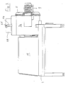
- the food processing apparatus shown in particular in Figures 1 and 7 comprises a mixing drum 2 which is arranged at a clear distance above the floor on a base frame 1 and which can be closed Ren upper inlet 3 and a lower outlet slide 4 has.
- an end cover 5 is articulated, which can be pivoted about a vertical axis 6.
- an angularly shaped transport wing 8 which is provided with its own drive 7, is centrally supported, the horizontal leg 8a of which rests with a scraping edge 9 on the inner wall of the drum casing 2a of the mixing drum 2 (see also FIG. 8).
- a horizontal tool shaft 10 is overhung in the mixing drum 2 and lies parallel to and below the central drum axis 11.
- the mixing drum 2 is flanged on its rear end wall 12 with a main motor 13 which drives the tool shaft 10 projecting through the rear end wall 12.
- Mixing drum 2 and main motor 13 are mounted on vibrating metal 14 on the top of the base frame 1.
- the main motor 13 is located within a housing cover 15, which i.a. encloses a hydraulic drive 16 for actuating the outlet slide 4.
- a water metering line 17 is welded into the upper region of the rear end wall 12, from which water can be sprayed against the inner wall of the drum casing 2a at a defined angle.
- the one-piece outlet slider 4 is contoured on its side facing the interior of the mixing drum 2, that is to say it lies exactly inside the inner contour of the mixing drum 2.
- the lower discharge opening 19 is surrounded by a drop frame 20 which is made of steel and is only a few millimeters wide and a few Has tenths of a millimeter raised sealing surfaces 21 which cooperate with the top of two longitudinal strips 22 arranged on the circumference of the outlet slide 4.
- the guide for the outlet slide 4 consists of two guide strips 23 arranged in the direction of displacement and engaging under the two longitudinal strips 22, each of which detachably hang from a holding and tensioning device fastened to the drop frame 20.
- the latter consists of an angle piece 24 fastened to the drop frame 20, which engages with its vertical leg 24a into a longitudinal groove of a clamping plate 25 fastened to the guide bar 23.
- This clamping plate 25 carries an upwardly projecting threaded bolt 26 which projects through an insertion slot 27 of the angle piece 24 which is open to the side and carries on its free end a tension nut 28 which presses on the angle piece 24 via a plate spring 29.
- Comparable sealing surfaces 21 interact with cross strips 22a provided in the two end regions of the outlet slide 4 (see FIG. 7d).
- the outlet slide 4 hangs on a hydraulic rod 30 actuated by the hydraulic drive 16.
- the outlet slide 4 acts on a limit switch 32 (see FIG. 8), which in this position releases various functions of the device.
- a central passage opening 33 is provided through which a spline shaft 34 acted upon by drive 7 projects, onto which the transport wing 8 with a bush 35 is pushed in a rotationally fixed manner.
- the passage opening 33 has a considerably larger diameter than the spline shaft 34.
- a sliding seal 36 which consists of two identical steel rings with a rubber sleeve, is pushed into the annular space formed in this way.
- a large-sized cap nut 38 is screwed onto a threaded bolt 37 fastened to the end face of the spline shaft 34 and, when tightened with an annular sealing lip 39, presses the bush 35 against the sliding seal 36 and thereby deforms it radially outward (see FIG. 7a).
- the seal between the rear end wall 12 and the tool shaft 10 corresponds essentially to the type described above, wherein instead of the threaded bolt 37 with the cap nut 38, a clamping nut 40 is provided in the form of a bayonet ring which is pushed onto the tool shaft 10 and with the help of a Lets the clamping tool be screwed into a corresponding receptacle of the rear end wall 12, the sliding seal 36 located in the annular space between the tool shaft 10 and the end wall 12 being acted upon and deformed outward in the radial direction (see FIG. 7c).
- the tool shaft 10 can rotate at 750-1 200 rpm when the food processing device is used as a kneading machine.
- the scraping edge 9 of the transport wing 8 consists of a plastic strip which is easily detachably fixed by a clamping strip 41 screwed to the horizontal leg 8a (see FIG 8th).
- the free end of the tool shaft 10 has an undercut radial slot 42 which is open to the front and into which a cross bolt 43 of a tool sleeve 44 inserted onto the tool shaft 10 engages, which carries the tools 45 and an annular collar 46 on its end facing the end cover 5 has a small clear distance a from the cap nut 38 which fixes the transport wing 8 (see FIGS. 7a + 7b).
- Transport wing 8 and tools 45 can be assembled and disassembled quickly and easily.
- the cap nut 38 is loosened, whereupon the transport wing 8 can be pulled off the spline shaft 34.
- the sliding seal 36 can then be pulled out.
- the annular space between the spline shaft 34 and the end cover 5 is exposed, so that a simple flushing through this annular space is possible for cleaning; the rinse water then escapes to the outside.
- the scraping edge 9 can be removed and cleaned quickly and easily.
- the tool sleeve 44 only needs to be pulled off the tool shaft 10.
- the resulting annular space between the tool shaft 10 and the rear end wall 12 can also be flushed from the inside to the outside, the rinsing water outside the mixing drum 2 between its rear end wall 12 and the flanged main motor 13 exit.
- the transport wing and tools are installed accordingly. If the tool shaft 10 starts up when the device is started up, there is a slight relative rotation between the tool sleeve 44 and the tool shaft 10 due to the inertia or a resistance exerted on the tools 45 and thus an automatic locking by the cross pin 43 engaging behind the undercut of the radial slot 42 . Should there nevertheless be a displacement of the tool sleeve 44 on the tool shaft 10 in the axial direction, then the annular collar 46 of the tool sleeve 44 would immediately contact the cap nut 38 and thus limit the axial displacement and render it harmless.
- the tool sleeve 44 can carry tools for comminuting, cutting, rubbing, stirring, mixing, quantity, emulsifying and / or kneading.
- FIGS. 7 and 8 show an example of a kneading tool which is particularly suitable for firmer doughs.
- the tool sleeve 44 carries two identically designed U-shaped kneading tools 45, which are offset from one another by 180 ° and fastened at an axial distance from one another on the opposite sides of the tool sleeve 44 such that the ends of the adjacent U-legs 45a of the two tools 45 lie on one sleeve side and that of the two axially outermost U-legs 45b on the other sleeve side (see FIG. 7).
- the two tools 45 together form an apparently closed curve in the form of a flat rectangle (see FIG. 8).
- the two tools 45 are bent from round material and are therefore very easy to clean.
- FIGS. 5 and 8 show that the upper inlet 3 of the mixing drum 2 in the drum casing 2a can be arranged somewhat below its highest point on the operating side. This arrangement is useful if the loading of the mixing drum 2 is done manually and at the same time a possibility to observe the interior of the drum is to be provided.
- an upper loading opening 47 is surrounded on all sides by a flat funnel 48, which consists of hollow walls and comprises a flap 49. This consists of transparent material and is contoured on the inside; it is detachably held on its higher longitudinal edge on a pivot axis 50 lying parallel to the drum axis 11.
- the pivot axis 50 has two plug pins 51 connected to the flap 49, of which one plug pin is inserted in the axial direction into a first eyelet 52, while the other plug pin with a not shown flattening in the radial direction into a correspondingly dimensioned insertion slot 53 of a second eyelet 52 is pushed.
- the flap 49 is locked via a pivotable toggle handle 54, which is detachably fixed to the flap 49 via a screw connection 55.
- the funnel 48 has a pocket-shaped undercut 56 in its lower longitudinal wall for engagement with the toggle handle 54.
- a support collar 57, possibly formed by the drum casing 2a, for the flap 49 is provided within the funnel 48.
- this support collar 57 has a recess forming a drain opening 58, into which the flap engages flush with a correspondingly dimensioned sealing strip 59 when the flap 49 is closed.
- the inner surface 60 of the lower-lying longitudinal wall of the funnel 48 is only inclined flatly upwards with respect to the horizontal (see in particular FIG. 8).
- Figure 6 shows a modified embodiment for the upper inlet 3.
- the upper inlet 3 lies at the highest point of the drum casing 2a and is overlapped on all sides by a connecting piece 61 which has hose and pipe connections 62 and a viewing and operating flap 63.
- the front cover 5 has an eccentric toggle lever lock 64, which comprises an easily removable axis of rotation 66 which supports the hand lever 65.
- a container trolley 67 which can be pulled out of the base frame 1 is arranged below the outlet slide 4 and, in its filling position shown, acts on a stop switch (not shown). When the container car 67 is pulled out, it sets Stop switch the machine silent.
- a conveyor device 69 is pushed under the outlet slide 4 instead of a container wagon.
- FIGs 1, 2, and 5 show the flap 49 in the open position, while this flap is closed in the representations in Figures 4 and 8.
- the flap has been omitted for clarity.
- the flap is locked via a magnetic switch, not shown. If a working operation under vacuum is provided for the device, the flap 49 is provided with a corresponding seal.
- a position circuit is provided for the transport wing 8 to ensure that the transport wing does not stop below the upper inlet 3 or above the outlet slide 4.
- the front cover 5 acts in its closed position on a limit switch, not shown, which stops the machine when the front cover is opened.
Landscapes
- Life Sciences & Earth Sciences (AREA)
- Engineering & Computer Science (AREA)
- Food Science & Technology (AREA)
- Food-Manufacturing Devices (AREA)
- Formation And Processing Of Food Products (AREA)
- Accessories For Mixers (AREA)
- General Preparation And Processing Of Foods (AREA)
- Electrical Discharge Machining, Electrochemical Machining, And Combined Machining (AREA)
- Control And Other Processes For Unpacking Of Materials (AREA)
- Apparatuses For Bulk Treatment Of Fruits And Vegetables And Apparatuses For Preparing Feeds (AREA)
- Mixers Of The Rotary Stirring Type (AREA)
- Manufacturing And Processing Devices For Dough (AREA)
- Refuse Collection And Transfer (AREA)
- Bakery Products And Manufacturing Methods Therefor (AREA)
Abstract
Description
Die Erfindung betrifft eine Nahrungsmittelverarbeitungsvorrichtung mit einer mit lichtem Abstand über dem Boden liegend auf einem Grundrahmen angeordneten Trommel, die einen verschließbaren oberen Einlaß, einen unteren, einteilig und auf seiner dem Innenraum der Trommel zugewandten Seite konturfolgend ausgebildeten Auslaßschieber sowie einen angelenkten Stirndeckel aufweist, in dem zentrisch ein mit einem eigenen Antrieb versehener, winkelförmig ausgebildeter Transportflügel gelagert ist, dessen horizontaler Schenkel mit einer Schabkante an der Innenwandung des Trommelmantels der Trommel anliegt, in der parallel zu und unterhalb von ihrer Trommelachse eine horizontale Werkzeugwelle fliegend gelagert ist, die auswechselbare Werkzeuge zum Zerkleinern, Schneiden, Reiben, Rühren, Mischen, Mengen, Emulgieren und/oder Kneten trägt, durch die rückwärtige Stirnwandung der Trommel ragt und mit einem ebenfalls auf dem Grundrahmen angeordneten Hauptmotor in Drehverbindung steht, wobei der Auslaßschieber an seinem Umfang vier Leisten aufweist, die abdichtend gegen einen die untere Ausfallöffnung umgebenden, fest mit der Trommel verbundenen Ausfallrahmen anliegen und die Führung für den Auslaßschieber aus zwei in Verschieberichtung angeordneten, zwei Längsleiten des Auslaßschiebers untergreifenden Führungsleisten besteht.The invention relates to a food processing device with a drum lying at a clear distance above the floor on a base frame, which has a closable upper inlet, a lower, one-piece and on its side facing the interior of the drum contoured outlet slide and an articulated front cover in which Centrally, an angularly designed transport wing with its own drive is mounted, the horizontal leg of which rests with a scraping edge on the inner wall of the drum shell of the drum, in which a horizontal tool shaft is overhung parallel to and below its drum axis, the interchangeable tools for shredding , Cutting, rubbing, stirring, mixing, quantity, emulsifying and / or kneading, protrudes through the rear end wall of the drum and is rotatably connected to a main motor also arranged on the base frame, the outlet slider has on its circumference four strips which lie sealingly against a failure frame surrounding the lower discharge opening, firmly connected to the drum, and the guide for the outlet slide consists of two guide strips arranged in the direction of displacement and engaging two longitudinal lines of the outlet slide.
Eine derartige Ausführungsform läßt sich der DE-B-2434330 entnehmen. Durch die nach unten verlegte, exzentrische Anordnung der Werkzeugwelle lassen sich auch kleinere Füllmengen mit den Werkzeugen bearbeiten ; es wird außerdem eine gute Durchmischung erzielt. Die Trommel kann z. B. etwa 150 I fassen, so daß sich in der Trommel bis zu 100 kg Masse bearbeiten läßt.Such an embodiment can be found in DE-B-2434330. Due to the downward, eccentric arrangement of the tool shaft, even small quantities can be processed with the tools; good mixing is also achieved. The drum can e.g. B. hold about 150 I, so that up to 100 kg mass can be processed in the drum.
Da es sich um eine Nahrungsmittelverarbeitungsvorrichtung handelt, kommt der Reinigungsmöglichkeit der Maschine eine besondere Bedeutung zu. Der Erfindung liegt somit die Aufgabe zugrunde, die eingangs erläuterte Vorrichtung so zu konzipieren, daß sich insbesondere der Auslaßschieber, der Transportflügel sowie die Werkzeugwelle einfach, schnell und zuverlässig reinigen lassen.Since it is a food processing device, the possibility of cleaning the machine is of particular importance. The invention is therefore based on the object of designing the device explained at the outset so that in particular the outlet slide, the transport wing and the tool shaft can be cleaned easily, quickly and reliably.
Diese Aufgabe wird gemäß der Erfindung durch folgende Merkmale gelöst :
- a) Der Auslaßschieber besteht aus Kunststoff ;
- b) die beiden genannten Führungsleisten hängen lösbar jeweils an einer am Ausfallrahmen befestigten Halte- und Spanneinrichtung ;
- c) zum leichten Demontieren und Reinigen bzw. Spülen weisen die im angelenkten Stirndeckel vorgesehene zentrische Durchtrittsöffnung für die Antriebswelle des Transportflügels ebenso wie die exzentrische, in der rückwärtigen Stirnwandung vorgesehene Durchtrittsöffnung für die Werkzeugwelle einen erheblich größeren Durchmesser auf als die durchgeführte Welle, wobei in den so gebildeten Ringraum eine Gleitdichtung geschoben ist, die durch Anziehen einer auf der Welle sitzenden Spannmutter radial nach außen wirkt und somit dichtet.
- a) The outlet slide is made of plastic;
- b) the two guide strips mentioned releasably each hang from a holding and tensioning device attached to the drop frame;
- c) for easy disassembly and cleaning or rinsing, the central passage opening provided for the drive shaft of the transport wing in the hinged end cover as well as the eccentric passage opening provided in the rear end wall for the tool shaft have a considerably larger diameter than the shaft carried out, whereby in the an annular seal formed in this way is pushed, which acts radially outwards by tightening a clamping nut seated on the shaft and thus seals.
Dabei ist es zweckmäßig, wenn der Ausfallrahmen den Leisten des Auslaßschiebers zugeordnete Abdichtflächen aufweist, die aus Stahl bestehen und nur wenige Millimeter breit und wenige zehntel Millimeter erhaben sind. Gleichzeitig ist es vorteilhaft, wenn die Halte- und Spanneinrichtung für jede Führungsleiste aus einem am Ausfallrahmen befestigten Winkelstück besteht, das mit seinem lotrechten Schenkel in eine Längsnut einer an der Führungsleiste befestigten Spannplatte eingreift, die einen nach oben ragenden Gewindebolzen trägt, der durch einen zur Seite hin offenen Einschubschlitz des Winkelstücks ragt und auf seinem freien Ende eine Spannmutter trägt, die über eine Tellerfeder auf das Winkelstück drückt. Einerseits läßt sich durch bloßes Lösen der beiden Spannmuttern der Auslaßschieber schnell und einfach ausbauen. Andererseits läßt sich durch die Anordnung der Tellerfedern beim Anziehen der Spannmuttern ein definierter Anpreßdruck zwischen den genannten Abdichtflächen und den Längsleisten des Auslaßschiebers erzielen. Dadurch werden eine zuverlässige Abdichtung und gleichzeitig eine klemm- und ruckfreie Verschiebung des Auslaßschiebers gewährleistet. Die vorstehend genannte Ausbildung der Abdichtflächen gewährleistet einen ausreichend großen Flächendruck und minimiert den Verschließ. Abdichtung, Verschleiß und Gleiteigenschaften des Auslaßschiebers sind dann optimal, wenn der Auslaßschieber aus Polyamid besteht. Dieses Material ermöglicht zudem eine einfache und zuverlässige Reinigung des Schiebers.It is expedient if the drop frame has sealing surfaces assigned to the strips of the outlet slide, which are made of steel and are only a few millimeters wide and a few tenths of a millimeter raised. At the same time, it is advantageous if the holding and tensioning device for each guide rail consists of an angle piece fastened to the drop frame, which engages with its vertical leg in a longitudinal groove of a tensioning plate fastened to the guide rail, which carries an upwardly projecting threaded bolt which is supported by a Insert slot of the contra-angle protrudes from the side and carries a tension nut on its free end, which presses on the contra-angle via a disc spring. On the one hand, the outlet slide can be removed quickly and easily by simply loosening the two clamping nuts. On the other hand, through the arrangement of the disc springs when the clamping nuts are tightened, a defined contact pressure can be achieved between the sealing surfaces mentioned and the longitudinal strips of the outlet slide. This ensures a reliable seal and at the same time a jam-free and jerk-free displacement of the outlet slide. The above-mentioned design of the sealing surfaces ensures a sufficiently large surface pressure and minimizes the wear. Sealing, wear and sliding properties of the outlet slide are optimal when the outlet slide is made of polyamide. This material also enables easy and reliable cleaning of the slide.
Die Gleitdichtungen für die Transportflügel - sowie die Werkzeugwelle bestehen vorzugsweise jeweils aus zwei identischen Stahlringen mit Gummimanschette. Der Transportflügel ist erfindungsgemäß mit einer die Gleitdichtung beaufschlagenden Buchse auf die durch den Stirndeckel ragende, als Keilwelle ausgebildete Antriebswelle gesteckt und durch eine großdimensionierte Hutmutter lösbar festgelegt, die auf einem an der Stirnseite der Keilwelle befestigten Gewindebolzen geschraubt ist und mit einer ringförmigen Dichtlippe gegen die genannte Buchse gepreßt wird. Die die Gleitdichtung der Werkzeugwelle beaufschlagende Spannmutter ist vorzugsweise ein Bajonettring. Durch Lösen der Hutmutter läßt sich der Transportflügel in einfacher Weise von der Keilwelle abziehen. Dadurch wird die Gleitdichtung freigegeben, die sich dann ebenso einfach von der Keilwelle abziehen läßt. Dadurch wird der vorstehend erläuterte Ringraum freigegeben, durch den nunmehr in einfacher und zuverlässiger Weise eine Spülungsreinigung vom Trommelinnenraum nach außen vorgenommen werden kann. Das Spülwasser läuft außerhalb der Trommel ab. In gleicher Weise läßt sich die Gleitdichtung der Werkzeugwelle durch Lösen des genannten Bajonettringes freilegen. Nach dem Abziehen der Gleitdichtung kann auch hier eine Reinigungsspülung aus dem Trommelinnenraum nach außen durch den freigelegten Ringraum hindurch erfolgen.The sliding seals for the transport wing and the tool shaft preferably each consist of two identical steel rings with a rubber sleeve. The transport wing is, according to the invention, inserted with a bushing which acts on the sliding seal on the drive shaft which projects through the end cover and is designed as a spline shaft and is detachably fixed by a large cap nut which is screwed onto a threaded bolt fastened to the end face of the spline shaft and with an annular sealing lip against the aforementioned Socket is pressed. The clamping nut acting on the sliding seal of the tool shaft is preferably a bayonet ring. By loosening the cap nut, the transport wing can be easily removed from the spline shaft. This releases the sliding seal, which can then be removed from the spline just as easily. As a result, the annular space explained above is released, by means of which flushing cleaning can now be carried out from the drum interior to the outside in a simple and reliable manner. The rinse water runs off outside the drum. In the same way, the slide seal of the tool shaft can be exposed by loosening the bayonet ring. To after the sliding seal has been removed, a cleaning rinse can also be carried out from the inside of the drum through the exposed annular space.
Der obere Einlaß der Trommel kann im Trommelmantel etwas unterhalb seiner höchsten Stelle zur Bedienungsseite hin angeordnet sein. Dadurch läßt sich die Vorrichtung trotz ihrer großen Kapazität auch von mittelgroßen Menschen einfach bedienen. Dennoch bestehen verschiedene Alternativen für den Abtransport des fertigen Produktes. So läßt sich die Trommel auf dem Grundrahmen so hoch anordnen, daß sich unter den Auslaßschieber z. B. ein Containerwagen oder aber eine Förderbandeinrichtung schieben läßt.The upper inlet of the drum can be arranged in the drum jacket somewhat below its highest point on the operating side. This allows the device to be operated easily even by medium-sized people, despite its large capacity. Nevertheless, there are various alternatives for the removal of the finished product. So the drum can be arranged on the base frame so high that z. B. can push a container wagon or a conveyor belt device.
Für eine manuelle Beschickung der Trommel ist es vorteilhaft, wenn die obere Beschickungsöffnung durch eine Klappe verschließbar ist, die aus durchsichtigem Material besteht, auf ihrer Innenseite konturfolgend ausgebildet ist und auf einer parallel zur Trommelachse liegenden Verschwenkachse lösbar gehalten ist. Dadurch ist einerseits die manuelle Zugabe von Zutaten möglich ; andererseits läßt sich die Materialbearbeitung durch die Klappe beobachten.For manual loading of the drum, it is advantageous if the upper loading opening can be closed by a flap, which is made of transparent material, is contoured on its inside and is detachably held on a pivot axis lying parallel to the drum axis. On the one hand, this enables the manual addition of ingredients; on the other hand, the material processing can be observed through the flap.
Wenn die durchsichtige Klappe auf ihrer Innenseite konturfolgend ausgebildet ist, würde der Transportflügel mit seiner Schabkante auch die Klappe überstreichen. Bei zum Schmieren neigenden Massen wird dadurch die Transparenz der Klappe stark beeinträchtigt. Es kann daher vorteilhaft. sein, wenn zumindest ein Teilbereich der konturfolgenden Innenfläche der Klappe gegenüber der Innenfläche des Trommelmantels etwas zurückgesetzt ist. Schon bei etwa um 1 mm zurückgesetzter Innenfläche bleibt die Klappe in diesem Bereich klar.If the transparent flap is designed to follow the contour on its inside, the transport wing with its scraping edge would also paint over the flap. With masses that tend to smear, the transparency of the flap is greatly impaired. It can therefore be beneficial. be when at least a portion of the contour-following inner surface of the flap is slightly set back from the inner surface of the drum shell. Even with the inner surface set back by about 1 mm, the flap remains clear in this area.
Die Beschickung der Trommel kann aber auch über einen Schnorchel, Trichter, einen Schlauch o. dergl. vollautomatisch erfolgen. Die Klappe wird dann ersetzt durch einen fest aufgesetzten Trichter mit entsprechenden Anschlüssen.The drum can also be loaded fully automatically via a snorkel, funnel, hose or the like. The flap is then replaced by a fixed funnel with appropriate connections.
Der Trommelmantel kann als Doppelwandung ausgebildet sein, wenn eine Kühlung und/oder Beheizung der Trommel gewünscht wird. Die Vorrichtung kann auch für Betrieb im Unter- bzw. Überdruck ausgelegt werden. Es können dann in die Trommel mündende Dampfventile o. dergl. vorgesehen sein.The drum jacket can be designed as a double wall if cooling and / or heating of the drum is desired. The device can also be designed for operation in negative or positive pressure. Steam valves or the like opening into the drum can then be provided.
In die Trommel ragt zweckmäßig ein elektronisches Thermometer zur exakten Temperaturmessung. An der auf der Bedienungsseite vorgesehenen Schalttafel kann eine Zeitwahluhr zur Vorgabesteuerung und Beendigung z. B. der Knetzeiten vorgesehen sein. Ferner kann ein Leistungs-Zeit-schreiber oder aber ein Strom-Zeit-Schreiber vorgesehen sein. An den Aufzeichnungen läßt sich dann der optimale Knetverlauf bzw. die optimale Energieeinbringung in die aufzubereitende Masse ablesen.An electronic thermometer expediently protrudes into the drum for exact temperature measurement. On the control panel provided on the operating side, a timer for default control and termination z. B. kneading times may be provided. Furthermore, a performance time recorder or a current time recorder can be provided. The optimal kneading process or the optimal introduction of energy into the mass to be prepared can then be read from the records.
Durch die in den Ansprüchen 10 bis 13 enthaltenen Merkmale ergibt sich eine leicht aus- bzw. einzubauende Klappe, die sich 'einfach und schnell reinigen läßt. Auch der Knebelgriff in der Platte läßt sich schnell demontieren. Die taschenförmige Hinterschneidung ist möglichst groß und mit flachen Rundungen ausgebildet, so daß auch hier eine sichere und einfache Reinigung möglich ist. Die genannte Ablauföffnung läßt liegengebliebenes oder beim Öffnen der Klappe herausgespritztes Material wieder in den Trommelinnenraum abfließen. Hierzu ist es vörteilhaft, wenn die Ablauföffnung in der tieferliegenden Trichterlängswandung vorgesehen ist, deren Innenfläche gegenüber der Horizontalen nur flach nach oben geneigt ist.The features contained in
Weitere Merkmale sind Gegenstand weiterer Unteransprüche und werden anhand von Ausführungsbeispielen näher erläutert.Further features are the subject of further subclaims and are explained in more detail using exemplary embodiments.
Durch die Erfindung wurde eine funktionssichere, bedienerfreundliche Nahrungsmittelverarbeitungsmaschine geschaffen, deren Ein- und Auslaß eine unkomplizierte Konzeption aufweisen und wasser- und ggf. auch vakuumdicht sein können. Die neue Vorrichtung wird höchsten Anforderungen an Hygiene unter Vermeidung von Spalten und schlecht zu reinigenden Stellen in den Food-Zonen gerecht. Für eine unkomplizierte Reinigung sind die Teile im Food-Zonen-Bereich mit wenigen Handgriffen montier- bzw. demontierbar.The invention has created a functionally reliable, user-friendly food processing machine, the inlet and outlet of which have an uncomplicated design and can be water-tight and possibly also vacuum-tight. The new device meets the highest hygiene requirements while avoiding gaps and difficult-to-clean areas in the food zones. For easy cleaning, the parts in the food zone area can be assembled and disassembled in a few simple steps.
In der Zeichnung sind einige als Beispiele dienende Ausführungsformen der Erfindung dargestellt. Es zeigen :
Figur 1 in Seitenansicht eine Nahrungsmittelverarbeitungsvorrichtung mit einem eingefahrenen Containerwagen ;Figur 2 eineDarstellung gemäß Figur 1, wobei der Containerwagen durch eine Fördereinrichtung ersetzt ist ;Figur 3 die Vorrichtung gemäß Figur 1 (ohne Containerwagen) in Rückansicht ;Figur 4 die Vorrichtung gemäßFigur 1 in Draufsicht ;Figur 5 die Vorrichtung gemäßFigur 3 in vorderer Stirnansicht ;- Figur 6 eine abgewandelte Ausführungsform in einer Darstellung gemäß Figur 5 ;
Figur 7 einen Längsschnitt durch die Vorrichtung gemäß Figur 1 (ohne Containerwagen) ;- Figur 7a in vergrößertem Maßstab im Längsschnitt das in
Figur 7 mit einem strichpunktierten Kreis I markierte Detail ; - Figur 7b in der in
Figur 7 eingezeichneten Blickrichtung II in vergrößertem Maßstab die Stirnseite der Werkzeugwelle ; - Figur 7c in vergrößertem Maßstab im Längsschnitt das in
Figur 7 mit dem Pfeil 111 markierte Detail ; - Figur 7d in vergrößertem Maßstab einen Auslaßschieber in einer Darstellung gemäß Figur 7 und
Figur 8 in vergrößertem Maßstab im Ausschnitt einen Querschnitt gemäß der Linie VIII-VIII inFigur 7.
- 1 shows a side view of a food processing device with a retracted container wagon;
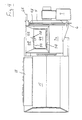
- Figure 2 is an illustration according to Figure 1, wherein the container car is replaced by a conveyor;
- Figure 3 shows the device of Figure 1 (without container car) in rear view;
- Figure 4 shows the device of Figure 1 in plan view;
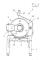
- FIG. 5 shows the device according to FIG. 3 in a front end view;
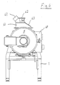
- FIG. 6 shows a modified embodiment in a representation according to FIG. 5;
- FIG. 7 shows a longitudinal section through the device according to FIG. 1 (without container car);
- FIG. 7a on an enlarged scale in longitudinal section the detail marked with a dash-dotted circle I in FIG. 7;
- FIG. 7b in the viewing direction II shown in FIG. 7, on an enlarged scale, the end face of the tool shaft;
- FIG. 7c, on an enlarged scale, in longitudinal section, the detail marked with the arrow 111 in FIG. 7;
- Figure 7d on an enlarged scale an outlet slide in a representation according to Figure 7 and
- 8 shows, on an enlarged scale, a detail of a cross section along the line VIII-VIII in FIG. 7.
Die insbesondere in den Figuren 1 und 7 dargestellte Nahrungsmittelverarbeitungsvorrichtung umfaßt eine mit lichtem Abstand über dem Boden liegend auf einem Grundrahmen 1 angeordnete Mischtrommel 2, die einen verschließbaren oberen Einlaß 3 sowie einen unteren Auslaßschieber 4 aufweist. An dem in Figur 1 linken Ende der Mischtrommel 2 ist ein Stirndeckel 5 angelenkt, der um eine lotrechte Achse 6 verschwenkbar ist. In dem Stirndeckel 5 ist zentrisch ein mit einem eigenen Antrieb 7 versehener, winkelförmig ausgebildeter Transportflügel 8 gelagert, dessen horizontaler Schenkel 8a mit einer Schabkante 9 an der Innenwandung des Trommelmantels 2a der Mischtrommel 2 anliegt (siehe auch Figur 8). In der Mischtrommel 2 ist eine horizontale Werkzeugwelle 10 fliegend gelagert, die parallel zu und unterhalb von der zentrischen Trommelachse 11 liegt.The food processing apparatus shown in particular in Figures 1 and 7 comprises a mixing
Die Mischtrommel 2 ist auf ihrer rückwärtigen Stirnwandung 12 fest mit einem Hauptmotor 13 verflanscht, der die durch die rückwärtige Stirnwandung 12 ragende Werkzeugwelle 10 antriebt. Mischtrommel 2 und Hauptmotor 13 sind auf Schwingmetall 14 der Oberseite des Grundrahmens 1 gelagert. Der Hauptmotor 13 befindet sich innerhalb einer Gehäuseabdeckung 15, die u.a. einen hydraulischen Antrieb 16 zur Betätigung des Auslaßschiebers 4 umschließt.The mixing
In den oberen Bereich der rückwärtigen Stirnwandung 12 ist eine Wasserdosierleitung 17 eingeschweißt, aus der Wasser unter einem definierten Winkel gegen die Innenwandung des Trommelmantels 2a gespritzt werden kann. Nicht näher dargestellt sind ein Wasserzähler sowie eine in einer Schalttafel 18 vorgesehene Einstellvorrichtung, an der die gewünschte Wassermenge vorgegeben werden kann.A
Der einteilig ausgebildete Auslaßschieber 4 ist auf seiner dem Innenraum der Mischtrommel 2 zugewandten Seite konturfolgend ausgebildet, liegt also exakt innerhalb der Innenkontur der Mischtrommel 2. Die untere Ausfallöffnung 19 ist von einem Ausfallrahmen 20 umgeben, der aus Stahl bestehende, nur wenige Millimeter breite und wenige zehntel Millimeter erhabene Abdichtflächen 21 aufweist, die mit der Oberseite von zwei am Umfang des Auslaßschiebers 4 angeordneten Längsleisten 22 zusammenwirken. Die Führung für den Auslaßschieber 4 besteht aus zwei in Verschieberichtung angeordneten, die beiden Längsleisten 22 untergreifenden Führungsleisten 23, die lösbar jeweils an einer am Ausfallrahmen 20 befestigten Halte- und Spanneinrichtung hängen. Letztere besteht aus einem am Ausfallrahmen 20 befestigten Winkelstück 24, das mit seinem lotrechten Schenkel 24a in eine Längsnut einer an der Führungsleiste 23 befestig- .ten Spannplatte 25 eingreift. Diese Spannplatte 25 trägt einen nach oben ragenden Gewindebolzen 26, der durch einen zur Seite hin offenen Einschubschlitz 27 des Winkelstücks 24 ragt und auf seinem freien Ende eine Spannmutter 28 trägt, die über eine Tellerfeder 29 auf das Winkelstück 24 drückt. Vergleichbare Abdichtflächen 21 wirken mit in den beiden Stirnbereichen des Auslaßschiebers 4 vorgesehenen Querleisten 22a zusammen (s. Fig. 7d).The one-
An seiner rückwärtigen Stirnseite hängt der Auslaßschieber 4 an einer von dem hydraulischen Antrieb 16 betätigten Hydraulikstange 30.On its rear end face, the
Durch Anziehen der beiden Spannmuttern 28 ergibt sich aufgrund der zwischengeschalteten Tellerfedern 29 ein definierter Anpreßdruck zwischen den Abdichtflächen 21 und den Leisten des Auslaßschiebers 4 und dadurch eine zuverlässige Abdichtung, die dennoch ein klemmfreies Verschieben des Auslaßschiebers 4 zuläßt. Zum Ausbau des Auslaßschiebers 4 werden lediglich die beiden Spannmuttern 28 gelöst, die im übrigen zusammen mit den Tellerfedern 29 auf den Gewindebolzen 26 verbleiben können. Die Führungsleisten 23 lassen sich dann in einfacher Weise zur Seite hin abziehen, wobei die Gewindebolzen 26 aus dem ihnen zugeordneten Einschubschlitz 27 herausgezogen werden. Der Auslaßschieber. 4 klappt dann nach unten weg, bis er an einem Klotz 31 anliegt. Der weiterhin an der Hydraulikstange 30 hängende Auslaßschieber 4 sowie Ausfallöffnung 19, Ausfallrahmen 20 sowie die Halte-und Spanneinrichtung 24 bis 29 lassen sich dann einfach, zuverlässig und schnell reinigen.Tightening the two clamping
In seiner Schließstellung beaufschlagt der Auslaßschieber 4 einen Endschalter 32 (siehe Figur 8), der in dieser Stellung verschiedene Funktionen der Vorrichtung freigibt.In its closed position, the
Im angelenkten Stirndeckel 5 ist eine zentrische Durchtrittsöffnung 33 vorgesehen durch die eine von Antrieb 7 beaufschlagte Keilwelle 34 ragt, auf die der Transportflügel 8 mit einer Buchse 35 drehfest aufgeschoben ist. Die Durchtrittsöffnung 33 weist einen erheblich größeren Durchmesser auf als die Keilwelle 34. In den so gebildeten Ringraum ist eine Gleitdichtung 36 geschoben, die aus zwei identischen Stahlringen mit Gummimanschette besteht. Auf einem an der Stirnseite der Keilwelle 34 befestigten Gewindebolzen 37 ist eine großdimensionierte Hutmutter 38 aufgeschraubt, die beim Anziehen mit einer ringförmigen Dichtlippe 39 die Buchse 35 gegen die Gleitdichtung 36 preßt und diese dadurch radial nach außen verformt (s. Fig. 7a).In the hinged
Die Abdichtung zwischen der rückwärtigen Stirnwandung 12 und der Werkzeugwelle 10 entspricht im wesentlichen der vorstehend erläuterten Bauart, wobei anstelle des Gewindebolzens 37 mit der Hutmutter 38 eine Spannmutter 40 in Form eines Bajonettringes vorgesehen ist, der auf die Werkzeugwelle 10 aufgeschoben ist und sich mit Hilfe eines Spannwerkzeuges in eine entsprechende Aufnahme der rückwärtigen Stirnwandung 12 eindrehen läßt, wobei die im Ringraum zwischen Werkzeugwelle 10 und Stirnwandung 12 befindliche Gleitdichtung 36 beaufschlagt und in radialer Richtung nach außen verformt wird (s. Fig. 7c).The seal between the
Während der Transportflügel langsam mit z. B. 20 U/min umläuft, kann die Werkzeugwelle 10 mit 750-1 200 U/min rotieren, wenn die Nahrungsmittelverarbeitungsvorrichtung als Knetmaschine eingesetzt wird.During the transport wing slowly with z. B. revolves 20 rpm, the
Die Schabkante 9 des Transportflügels 8 besteht aus einem Kunststoffstreifen, der durch eine mit dem horizontalen Schenkel 8a verschraubte Klemmleiste 41 leicht lösbar fixiert ist (siehe Figur 8). Das freie Ende der Werkzeugwelle 10 weist einen hinterschnittenen, nach vorn offenen Radialschlitz 42 auf, in den ein Querbolzen 43 einer auf die Werkzeugwelle 10 gesteckten Werkzeughülse 44 eingreift, die die Werkzeuge 45 und an ihrem dem Stirndeckel 5 zugewandten Ende einen Ringbund 46 trägt, der einen geringen lichten Abstand a von der den Transportflügel 8 festlegenden Hutmutter 38 aufweist (s. Fig. 7a + 7b).The
Transportflügel 8 und Werkzeuge 45 lassen sich schnell und einfach montieren und demontieren. Zur Demontage des Transportflügels 8 wird die Hutmutter 38 gelöst, worauf sich der Transportflügel 8 von der Keilwelle 34 abziehen läßt. Anschließend kann dann die Gleitdichtung 36 herausgezogen werden. Hierdurch wird der Ringraum zwischen Keilwelle 34 und Stirndeckel 5 freigelegt, so daß zur Reinigung eine einfache Durchspülung durch diesen Ringraum möglich ist ; das Spülwasser tritt dann nach außen aus. Durch Lösen der die Klemmleiste 41 haltenden Verschraubung läßt sich die Schabkante 9 schnell und einfach ausbauen und reinigen. Die Werkzeughülse 44 braucht lediglich von der Werkzeugwelle 10 abgezogen zu werden. Nach dem Lösen der Spannmutter 40 und dem Herausziehen der Gleitdichtung 36 kann auch hier der so entstehende Ringraum zwischen Werkzeugwelle 10 und rückwärtiger Stirnwandung 12 von innen nach außen durchspült werden, wobei das Spülwasser außerhalb der Mischtrommel 2 zwischen ihrer rückwärtigen Stirnwandung 12 und dem angeflanschten Hauptmotor 13 austritt.
Die Montage von Transportflügel und Werkzeug erfolgt entsprechend. Läuft die Werkzeugwelle 10 bei der Inbetriebnahme der Vorrichtung an, ergibt sich aufgrund der Massenträgheit bzw. eines auf die Werkzeuge 45 ausgeübten Widerstandes eine leichte Relativverdrehung zwischen Werkzeughülse 44 und Werkzeugwelle 10 und damit eine selbsttätige Verriegelung, indem der Querbolzen 43 die Hinterschneidung des Radialschlitzes 42 hintergreift. Sollte sich dennoch einmal eine Verschiebung der Werkzeughülse 44 auf der Werkzeugwelle 10 in axialer Richtung ergeben, dann würde sich sofort der Ringbund 46 der Werkzeughülse 44 an die Hutmutter 38 anlegen und so die Axialverschiebung begrenzen und unschädlich machen.The transport wing and tools are installed accordingly. If the
Die Werkzeughülse 44 kann Werkzeuge zum Zerkleinern, Schneiden, Reiben, Rühren, Mischen, Mengen, Emulgieren und/oder Kneten tragen. In den Figuren 7 und 8 ist als Ausführungsbeispiel ein Knetwerkzeug dargestellt, das sich insbesondere für festere Teige eignet. Hier trägt die Werkzeughülse 44 zwei gleich ausgebildete U-förmige Knetwerkzeuge 45, die um 180° gegeneinander versetzt und mit axialem Abstand voneinander so auf den sich gegenüberliegenden Seiten der Werkzeughülse 44 befestigt sind, daß die Enden der einander benachbarten U-Schenkel 45a der beiden Werkzeuge 45 auf der einen Hülsenseite und die der beiden axial äußersten U-Schenkel 45b auf der anderen Hülsenseite liegen (siehe Figur 7). In Stirnansicht der Werkzeughülse 44 bilden die beiden Werkzeuge 45 gemeinsam eine scheinbar geschlossene Kurve in Form eines flachen Rechteckes (siehe Figur 8). Die beiden Werkzeuge 45 sind aus Rundmaterial gebogen und -daher sehr einfach zu reinigen.The
Insbesondere die Figuren 5 und 8 lassen erkennen, daß der obere Einlaß 3 der Mischtrommel 2 im Trommelmantel 2a etwas unterhalb seiner höchsten Stelle zur Bedienungsseite hin angeordnet sein kann. Diese Anordnung ist dann zweckmäßig, wenn die Beschickung der Mischtrommel 2 manuell erfolgen und zugleich eine Möglichkeit zur Beobachtung des Trommelinnenraumes vorgesehen werden soll. Bei dieser Ausführungsform ist eine obere Beschickungsöffnung 47 allseitig von einem flachen Trichter 48 umgeben, der aus hohl ausgebildeten Wandungen besteht und eine Klappe 49 umfaßt. Diese besteht aus durchsichtigem Material und ist auf ihrer Innenseite konturfolgend ausgebildet; sie ist auf ihrer höherliegenden Längskante auf einer parallel zur Trommelachse 11 liegenden Verschwenkachse 50 lösbar gehalten. Die Verschwenkachse 50 weist zwei mit der Klappe 49 verbundene Steckzapfen 51 auf, von denen der eine Steckzapfen in Axialrichtung in eine erste Öse 52 gesteckt ist, während der andere Steckzapfen mit einer nicht dargestellten Anflächung in radialer Richtung in einen entsprechend dimensionierten Einschubschlitz 53 einer zweiten Öse 52 geschoben ist. Die Verriegelung der Klappe 49 erfolgt über einen verschwenkbaren Knebelgriff 54, der über eine Verschraubung 55 lösbar an der Klappe 49 festgelegt ist. Der Trichter 48 weist'in seiner tieferliegenden Längswandung eine taschenförmige Hinterschneidung 56 auf zum Eingriff für den Knebelgriff 54. Innerhalb der Trichters 48 ist ein ggf. vom Trommelmantel 2a gebildeter Auflagebund 57 für die Klappe 49 vorgesehen. Im Bereich der vorstehend genannten Hinterschneidung 56 weist dieser Auflagebund 57 eine eine Ablauföffnung 58 bildende Ausnehmung auf, in die bei geschlossener Klappe 49 die Klappe mit einer entsprechend dimensionierten Abdichtleiste 59 bündig eingreift. Die Innenfläche 60 der tiefer gelegenen Längswandung des Trichters 48 ist gegenüber der Horizontalen nur flach nach oben geneigt (siehe insbesondere Figur 8).In particular, FIGS. 5 and 8 show that the
Figur 6 zeigt für den oberen Einlaß 3 eine abgewandelte Ausführungsform. Hier liegt der obere Einlaß 3 an der höchsten Stelle des Trommelmantels 2a und ist allseitig von einem Anschlußstutzen 61 übergriffen, der Schlauch- und Rohranschlüsse 62 sowie eine Sicht- und Bedienungsklappe 63 aufweist.Figure 6 shows a modified embodiment for the
Der Stirndeckel 5 weist einen Exzenter-Kniehebel-Verschluß 64 auf, der eine leicht herausziehbare, den Handhebel 65 lagernde Drehachse 66 umfaßt.The
Gemäß Figur 1 ist unterhalb des Auslaßschiebers 4 ein aus dem Grundrahmen 1 herausziehbarer Containerwagen 67 angeordnet, der in seiner dargestellten Befüllstellung einen nicht dargestellten Anschlagschalter beaufschlagt. Beim Hervorziehen des Containerwagens 67 setzt dieser Anschlagschalter die Maschine still.According to FIG. 1, a
Bei der in Figur 2 dargestellten Ausführungsform ist anstelle eines Containerwagens eine Fördereinrichtung 69 unter den Auslaßschieber 4 geschoben.In the embodiment shown in FIG. 2, a
Die Figuren 1, 2, und 5 zeigen die Klappe 49 in geöffneter Lage, während diese Klappe bei den Darstellungen in den Figuren 4 und 8 geschlossen ist. In Figur 7 wurde die Klappe wegen der besseren Übersichtlichkeit weggelassen. Die Verriegelung der Klappe erfolgt über einen nicht näher dargestellten Magnetschalter. Ist für die Vorrichtung ein Arbeitsbetrieb unter Vakuum vorgesehen, wird die Klappe 49 mit einer entsprechenden Dichtung versehen.Figures 1, 2, and 5 show the
Für den Transportflügel 8 ist eine nicht näher dargestellte Positionsschaltung vorgesehen um sicherzustellen, daß der Transportflügel nicht unterhalb des oberen Einlasses 3 oder oberhalb des Auslaßschiebers 4 stehenbleibt.For the
Der Stirndeckel 5 beaufschlagt in seiner Schließstellung einen nicht dargestellten Endschalter, der beim Öffnen des Stirndeckels die Maschine stillsetzt.The
Claims (18)
Priority Applications (16)
| Application Number | Priority Date | Filing Date | Title |
|---|---|---|---|
| EP85111195A EP0213232B1 (en) | 1985-09-05 | 1985-09-05 | Food-processing apparatus |
| AT85111195T ATE35498T1 (en) | 1985-09-05 | 1985-09-05 | FOOD PROCESSING EQUIPMENT. |
| DE8585111195T DE3563587D1 (en) | 1985-09-05 | 1985-09-05 | Food-processing apparatus |
| US06/812,846 US4650337A (en) | 1985-09-05 | 1985-12-23 | Food processing device |
| ZA866651A ZA866651B (en) | 1985-09-05 | 1986-09-02 | Food processing device |
| SU864028156A SU1607682A3 (en) | 1985-09-05 | 1986-09-04 | All-purpose food-processing machine |
| DD86294152A DD249400A5 (en) | 1985-09-05 | 1986-09-04 | FOOD PROCESSING DEVICE |
| BR8604256A BR8604256A (en) | 1985-09-05 | 1986-09-04 | FOOD PROCESSING DEVICE |
| ES8601616A ES2001653A6 (en) | 1985-09-05 | 1986-09-04 | Food-processing apparatus. |
| CA000517598A CA1259067A (en) | 1985-09-05 | 1986-09-05 | Food processing device |
| YU1555/86A YU44593B (en) | 1985-09-05 | 1986-09-05 | Device for food working |
| CN86105937A CN1008683B (en) | 1985-09-05 | 1986-09-05 | Food processing machinery |
| JP61209398A JPH0755123B2 (en) | 1985-09-05 | 1986-09-05 | Food processing equipment |
| HR921260A HRP921260B1 (en) | 1985-09-05 | 1992-11-13 | Food processing apparatus |
| LTRP200A LT2031B (en) | 1985-09-05 | 1992-12-17 | UNIVERSAL FOOD PROCESSING MACHINE |
| LV930005A LV5169A3 (en) | 1985-09-05 | 1993-01-08 | Versatile machine for batch processing |
Applications Claiming Priority (1)
| Application Number | Priority Date | Filing Date | Title |
|---|---|---|---|
| EP85111195A EP0213232B1 (en) | 1985-09-05 | 1985-09-05 | Food-processing apparatus |
Publications (2)
| Publication Number | Publication Date |
|---|---|
| EP0213232A1 EP0213232A1 (en) | 1987-03-11 |
| EP0213232B1 true EP0213232B1 (en) | 1988-07-06 |
Family
ID=8193738
Family Applications (1)
| Application Number | Title | Priority Date | Filing Date |
|---|---|---|---|
| EP85111195A Expired EP0213232B1 (en) | 1985-09-05 | 1985-09-05 | Food-processing apparatus |
Country Status (14)
| Country | Link |
|---|---|
| US (1) | US4650337A (en) |
| EP (1) | EP0213232B1 (en) |
| JP (1) | JPH0755123B2 (en) |
| CN (1) | CN1008683B (en) |
| AT (1) | ATE35498T1 (en) |
| BR (1) | BR8604256A (en) |
| CA (1) | CA1259067A (en) |
| DD (1) | DD249400A5 (en) |
| DE (1) | DE3563587D1 (en) |
| ES (1) | ES2001653A6 (en) |
| LT (1) | LT2031B (en) |
| SU (1) | SU1607682A3 (en) |
| YU (1) | YU44593B (en) |
| ZA (1) | ZA866651B (en) |
Families Citing this family (35)
| Publication number | Priority date | Publication date | Assignee | Title |
|---|---|---|---|---|
| DE3831609A1 (en) * | 1988-09-17 | 1990-03-22 | Loedige Maschbau Gmbh Geb | MACHINE FOR TREATING SCHUETTABEIG, PASTOESER AND / OR FLOWABLE GOETER WITH BUILT-IN LOCKING DEVICE |
| DE4137161C2 (en) * | 1991-11-12 | 1994-02-24 | Stephan & Soehne | Process for preparing dough |
| US5176069A (en) * | 1992-06-02 | 1993-01-05 | Chen Hsing W | Mechanism for drying and frying meat |
| JP2829462B2 (en) * | 1992-09-16 | 1998-11-25 | ハウス食品株式会社 | Dough mixer |
| DE4339628C2 (en) * | 1993-11-20 | 2003-04-10 | Ismar Maschinen Gmbh | kneading |
| ES2133021B1 (en) * | 1995-06-12 | 2000-04-01 | Merino Cuesta Joaquin | IMPROVEMENTS INTRODUCED IN BLENDING MACHINES, MIXERS AND Kneaders. |
| US5727876A (en) * | 1996-05-31 | 1998-03-17 | E. I. Du Pont De Nemours And Company | Polymer mixing apparatus |
| US6863429B2 (en) * | 2002-01-07 | 2005-03-08 | Artos, S.A. | Dough mixer with metering device |
| US6767123B2 (en) | 2001-08-15 | 2004-07-27 | Morinaga & Co., Ltd. | Kneading device |
| RU2258449C1 (en) * | 2004-04-12 | 2005-08-20 | Федеральное государственное образовательное учреждение высшего профессионального образования "Волгоградская государственная сельскохозяйственная академия" | General-purpose food processing machine |
| RU2262876C1 (en) * | 2004-04-12 | 2005-10-27 | Салдаев Геннадий Александрович | General-purpose food product processing machine |
| FR2883704B1 (en) * | 2005-04-05 | 2007-06-01 | Vmi Sa | CONTINUOUS MIXING DEVICE FOR A FOOD PASTE COMPRISING TWO TYPES OF MIXED TOOLS AND LATERAL EXHAUST |
| DE102007050858A1 (en) * | 2007-10-24 | 2009-04-30 | Weber Maschinenbau Gmbh Breidenbach | Device for slicing a food product |
| RU2351273C1 (en) * | 2007-12-03 | 2009-04-10 | Федеральное государственное образовательное учреждение высшего профессионального образования "Волгоградская государственная сельскохозяйственная академия" | Multi-purpose machine for processing food products |
| JP5197095B2 (en) * | 2008-03-28 | 2013-05-15 | 株式会社オシキリ | Horizontal mixer |
| JP5334744B2 (en) * | 2009-08-14 | 2013-11-06 | 株式会社オシキリ | Horizontal mixer |
| US8382365B2 (en) | 2008-03-28 | 2013-02-26 | Oshikiri Machinery Ltd. | Horizontal mixer |
| ES1070102Y (en) * | 2009-03-30 | 2009-10-16 | Bonas Juan Vila | MACHINE PICADORA AND MIXER OF MEAT, OF ALTERNATIVE OPERATION |
| CN103029150A (en) * | 2012-12-18 | 2013-04-10 | 苏州麦克食品机械塑胶有限公司 | Food processing and cutting equipment |
| US9713893B2 (en) * | 2013-07-09 | 2017-07-25 | Wenger Manufacturing, Inc. | Method of preconditioning comestible materials using steam/water static mixer |
| KR101529426B1 (en) * | 2013-08-30 | 2015-06-16 | 가부시끼 가이샤 구보다 | Food material mixer |
| ITTO20130716A1 (en) * | 2013-09-05 | 2015-03-06 | Sancassiano Spa | BATHTUB FOR MIXER MACHINE |
| WO2016000781A1 (en) | 2014-07-03 | 2016-01-07 | Aktiebolaget Electrolux | Household appliance mixing arrangement |
| EP3164039B1 (en) * | 2014-07-03 | 2018-06-13 | Aktiebolaget Electrolux | Household appliance mixing arrangement |
| CN104457139B (en) * | 2014-12-09 | 2016-04-27 | 青海林丰农牧机械制造有限公司 | A kind of medicinal material kneading machine |
| CN104542781A (en) * | 2015-01-24 | 2015-04-29 | 朱建国 | Automatic batter output mixer |
| CN106614855A (en) * | 2015-10-29 | 2017-05-10 | 重庆市南川区云都挂面厂 | Low-noise dough kneader |
| RU2620791C1 (en) * | 2016-05-28 | 2017-05-29 | Федеральное государственное бюджетное образовательное учреждение высшего образования "Юго-Западный государственный университет" (ЮЗГУ) | Mixer-emulsifier |
| CN107836481A (en) * | 2016-09-20 | 2018-03-27 | 苏州润桐专利运营有限公司 | A mixer and noodle kneader with extrusion |
| CN106614876B (en) * | 2016-12-07 | 2022-03-04 | 北京金瑞典膳科技有限公司 | Household noodle maker |
| RU2674196C1 (en) * | 2018-01-09 | 2018-12-05 | Акционерное общество "Федеральный научно-производственный центр "Алтай" | Mobile mixer of components of mixed rocket solid fuel of gravitational type |
| DE102018106189A1 (en) | 2018-03-16 | 2019-09-19 | Maschinenfabrik Gustav Eirich Gmbh & Co. Kg | hygiene mixer |
| RU2682483C9 (en) * | 2018-08-01 | 2019-05-16 | Общество с ограниченной ответственностью "АКМАЛЬКО ИНЖИНИРИНГ" | Mixing-whipping machine and method for the production of yeast-free dough using it |
| CN111298704A (en) * | 2020-02-28 | 2020-06-19 | 山东理工职业学院 | Tiltable food processing mixer |
| CN111605978B (en) * | 2020-05-25 | 2021-07-02 | 安徽省好朋友食品有限公司 | Chocolate production is with preventing off tracking conveying equipment |
Citations (1)
| Publication number | Priority date | Publication date | Assignee | Title |
|---|---|---|---|---|
| DE2434330A1 (en) * | 1974-07-17 | 1976-01-29 | Stephan & Soehne | DOUGH MIXING AND MIXING MACHINE |
Family Cites Families (8)
| Publication number | Priority date | Publication date | Assignee | Title |
|---|---|---|---|---|
| DE172211C (en) * | ||||
| US172513A (en) * | 1876-01-18 | Improvement in folding wardrobes | ||
| US2837356A (en) * | 1955-09-15 | 1958-06-03 | J H Day Company Inc | Sanitary stuffing box |
| GB1064641A (en) * | 1964-04-09 | 1967-04-05 | Royal Industries | Mixing apparatus |
| AT329398B (en) * | 1970-07-08 | 1976-05-10 | Stephan & Soehne | FOOD PROCESSING DEVICE |
| US3727893A (en) * | 1971-07-19 | 1973-04-17 | Int Automation Inc | Apparatus for processing rubber, plastic and the like and parts thereof |
| US4075713A (en) * | 1976-11-11 | 1978-02-21 | Easton Harlan J | Feed mixer |
| JPS5914250B2 (en) * | 1981-02-06 | 1984-04-03 | 正夫 森山 | Leakage prevention device for kneading machines, etc. |
-
1985
- 1985-09-05 EP EP85111195A patent/EP0213232B1/en not_active Expired
- 1985-09-05 AT AT85111195T patent/ATE35498T1/en not_active IP Right Cessation
- 1985-09-05 DE DE8585111195T patent/DE3563587D1/en not_active Expired
- 1985-12-23 US US06/812,846 patent/US4650337A/en not_active Expired - Lifetime
-
1986
- 1986-09-02 ZA ZA866651A patent/ZA866651B/en unknown
- 1986-09-04 BR BR8604256A patent/BR8604256A/en unknown
- 1986-09-04 SU SU864028156A patent/SU1607682A3/en active
- 1986-09-04 DD DD86294152A patent/DD249400A5/en not_active IP Right Cessation
- 1986-09-04 ES ES8601616A patent/ES2001653A6/en not_active Expired
- 1986-09-05 JP JP61209398A patent/JPH0755123B2/en not_active Expired - Lifetime
- 1986-09-05 CN CN86105937A patent/CN1008683B/en not_active Expired
- 1986-09-05 CA CA000517598A patent/CA1259067A/en not_active Expired
- 1986-09-05 YU YU1555/86A patent/YU44593B/en unknown
-
1992
- 1992-12-17 LT LTRP200A patent/LT2031B/en unknown
Patent Citations (1)
| Publication number | Priority date | Publication date | Assignee | Title |
|---|---|---|---|---|
| DE2434330A1 (en) * | 1974-07-17 | 1976-01-29 | Stephan & Soehne | DOUGH MIXING AND MIXING MACHINE |
Also Published As
| Publication number | Publication date |
|---|---|
| US4650337A (en) | 1987-03-17 |
| CN1008683B (en) | 1990-07-11 |
| EP0213232A1 (en) | 1987-03-11 |
| JPS62201536A (en) | 1987-09-05 |
| SU1607682A3 (en) | 1990-11-15 |
| CA1259067A (en) | 1989-09-05 |
| ATE35498T1 (en) | 1988-07-15 |
| LT2031B (en) | 1993-04-15 |
| CN86105937A (en) | 1987-04-01 |
| ES2001653A6 (en) | 1988-06-01 |
| YU44593B (en) | 1990-10-31 |
| ZA866651B (en) | 1987-04-29 |
| DD249400A5 (en) | 1987-09-09 |
| DE3563587D1 (en) | 1988-08-11 |
| YU155586A (en) | 1988-08-31 |
| JPH0755123B2 (en) | 1995-06-14 |
| BR8604256A (en) | 1987-05-05 |
Similar Documents
| Publication | Publication Date | Title |
|---|---|---|
| EP0213232B1 (en) | Food-processing apparatus | |
| EP0439689B1 (en) | Mixgranulator | |
| EP0196291B1 (en) | Mixing device | |
| EP0225495A2 (en) | Mixing device | |
| DE19808903A1 (en) | Waste bin with slide-on lid | |
| DE202013103591U1 (en) | Inliner for lining a mixed container and arrangement comprising a mixing container and an inliner inserted therein | |
| EP0142003B2 (en) | Batch mixer | |
| DE19507181A1 (en) | Dough mixer assembly with horizontal contra-rotating concentric mixer blades | |
| DD244697A5 (en) | EXPRESS FILTER FOR SUSPENSIONS | |
| EP0532855A1 (en) | Device for making rubber mixtures | |
| EP0188717B1 (en) | Mixer | |
| DE2852532B2 (en) | Household machines for making and shaping pasta | |
| DE19757311A1 (en) | Kneading or blending machine for dough and food | |
| DE202010012473U1 (en) | Tank cleaning system | |
| DE29509271U1 (en) | Solids mill | |
| DE3941836A1 (en) | Grinding arrangement - includes housing, grinding cylinder, filling funnel, grinding blade, shaft, motor, bearings, seals, bushing and sealing plate | |
| DE1151717B (en) | Hammer mill for crushing inhomogeneous materials | |
| WO2022258171A1 (en) | Processing apparatus for foodstuffs | |
| DE20313741U1 (en) | Mobile animal feed mill-mixer container has cylindrical silo with conical base scraped clean by rotating blade and suction removal of residues | |
| DE69114521T2 (en) | WASTE COMPACTION PLANT AND APPARATUS DEVICE. | |
| DE19512584C1 (en) | Cutting and screening machine for separating large particles from liquid manure | |
| DE3217164A1 (en) | Cutter takeoff apparatus | |
| DE312237C (en) | ||
| AT399118B (en) | DEVICE FOR FILLING PRESS FORMS WITH ONE OR MORE MOLD OPENINGS ON PRESS FORMS OF A PRESS | |
| DE8902531U1 (en) | Grating device |
Legal Events
| Date | Code | Title | Description |
|---|---|---|---|
| PUAI | Public reference made under article 153(3) epc to a published international application that has entered the european phase |
Free format text: ORIGINAL CODE: 0009012 |
|
| 17P | Request for examination filed |
Effective date: 19860626 |
|
| AK | Designated contracting states |
Kind code of ref document: A1 Designated state(s): AT BE CH DE FR GB IT LI NL SE |
|
| ITCL | It: translation for ep claims filed |
Representative=s name: MODIANO & ASSOCIATI S.R.L. |
|
| TCNL | Nl: translation of patent claims filed | ||
| EL | Fr: translation of claims filed | ||
| 17Q | First examination report despatched |
Effective date: 19870626 |
|
| GRAA | (expected) grant |
Free format text: ORIGINAL CODE: 0009210 |
|
| AK | Designated contracting states |
Kind code of ref document: B1 Designated state(s): AT BE CH DE FR GB IT LI NL SE |
|
| REF | Corresponds to: |
Ref document number: 35498 Country of ref document: AT Date of ref document: 19880715 Kind code of ref document: T |
|
| GBT | Gb: translation of ep patent filed (gb section 77(6)(a)/1977) | ||
| REF | Corresponds to: |
Ref document number: 3563587 Country of ref document: DE Date of ref document: 19880811 |
|
| ET | Fr: translation filed | ||
| ITF | It: translation for a ep patent filed | ||
| PLBE | No opposition filed within time limit |
Free format text: ORIGINAL CODE: 0009261 |
|
| STAA | Information on the status of an ep patent application or granted ep patent |
Free format text: STATUS: NO OPPOSITION FILED WITHIN TIME LIMIT |
|
| 26N | No opposition filed | ||
| ITTA | It: last paid annual fee | ||
| EAL | Se: european patent in force in sweden |
Ref document number: 85111195.5 |
|
| PGFP | Annual fee paid to national office [announced via postgrant information from national office to epo] |
Ref country code: CH Payment date: 19970925 Year of fee payment: 13 |
|
| PG25 | Lapsed in a contracting state [announced via postgrant information from national office to epo] |
Ref country code: LI Free format text: LAPSE BECAUSE OF NON-PAYMENT OF DUE FEES Effective date: 19980930 Ref country code: CH Free format text: LAPSE BECAUSE OF NON-PAYMENT OF DUE FEES Effective date: 19980930 |
|
| REG | Reference to a national code |
Ref country code: CH Ref legal event code: PL |
|
| PGFP | Annual fee paid to national office [announced via postgrant information from national office to epo] |
Ref country code: SE Payment date: 19990823 Year of fee payment: 15 |
|
| PGFP | Annual fee paid to national office [announced via postgrant information from national office to epo] |
Ref country code: GB Payment date: 19990901 Year of fee payment: 15 |
|
| PGFP | Annual fee paid to national office [announced via postgrant information from national office to epo] |
Ref country code: FR Payment date: 19990924 Year of fee payment: 15 |
|
| PGFP | Annual fee paid to national office [announced via postgrant information from national office to epo] |
Ref country code: BE Payment date: 19990929 Year of fee payment: 15 Ref country code: AT Payment date: 19990929 Year of fee payment: 15 |
|
| PGFP | Annual fee paid to national office [announced via postgrant information from national office to epo] |
Ref country code: NL Payment date: 19990930 Year of fee payment: 15 |
|
| PG25 | Lapsed in a contracting state [announced via postgrant information from national office to epo] |
Ref country code: GB Free format text: LAPSE BECAUSE OF NON-PAYMENT OF DUE FEES Effective date: 20000905 Ref country code: AT Free format text: LAPSE BECAUSE OF NON-PAYMENT OF DUE FEES Effective date: 20000905 |
|
| PG25 | Lapsed in a contracting state [announced via postgrant information from national office to epo] |
Ref country code: SE Free format text: THE PATENT HAS BEEN ANNULLED BY A DECISION OF A NATIONAL AUTHORITY Effective date: 20000929 |
|
| PG25 | Lapsed in a contracting state [announced via postgrant information from national office to epo] |
Ref country code: BE Free format text: LAPSE BECAUSE OF NON-PAYMENT OF DUE FEES Effective date: 20000930 |
|
| BERE | Be: lapsed |
Owner name: A. STEPHAN U. SOHNE G.M.B.H. & CO. Effective date: 20000930 |
|
| PG25 | Lapsed in a contracting state [announced via postgrant information from national office to epo] |
Ref country code: NL Free format text: LAPSE BECAUSE OF NON-PAYMENT OF DUE FEES Effective date: 20010401 |
|
| GBPC | Gb: european patent ceased through non-payment of renewal fee |
Effective date: 20000905 |
|
| EUG | Se: european patent has lapsed |
Ref document number: 85111195.5 |
|
| PG25 | Lapsed in a contracting state [announced via postgrant information from national office to epo] |
Ref country code: FR Free format text: LAPSE BECAUSE OF NON-PAYMENT OF DUE FEES Effective date: 20010531 |
|
| NLV4 | Nl: lapsed or anulled due to non-payment of the annual fee |
Effective date: 20010401 |
|
| REG | Reference to a national code |
Ref country code: FR Ref legal event code: ST |
|
| PGFP | Annual fee paid to national office [announced via postgrant information from national office to epo] |
Ref country code: DE Payment date: 20011106 Year of fee payment: 17 |
|
| PG25 | Lapsed in a contracting state [announced via postgrant information from national office to epo] |
Ref country code: DE Free format text: LAPSE BECAUSE OF NON-PAYMENT OF DUE FEES Effective date: 20030401 |