EP0135697B1 - Mehrstufige Zerkleinerungsvorrichtung, insbesondere für Plaste, Polymerisate für die Bitumenmodifizierung, PTFE- u. Gummi-Regenerat, Schlachtabfälle für Tiernahrung usw - Google Patents
Mehrstufige Zerkleinerungsvorrichtung, insbesondere für Plaste, Polymerisate für die Bitumenmodifizierung, PTFE- u. Gummi-Regenerat, Schlachtabfälle für Tiernahrung usw Download PDFInfo
- Publication number
- EP0135697B1 EP0135697B1 EP84108592A EP84108592A EP0135697B1 EP 0135697 B1 EP0135697 B1 EP 0135697B1 EP 84108592 A EP84108592 A EP 84108592A EP 84108592 A EP84108592 A EP 84108592A EP 0135697 B1 EP0135697 B1 EP 0135697B1
- Authority
- EP
- European Patent Office
- Prior art keywords
- rotor
- teeth
- ring
- stator
- stage
- Prior art date
- Legal status (The legal status is an assumption and is not a legal conclusion. Google has not performed a legal analysis and makes no representation as to the accuracy of the status listed.)
- Expired
Links
- 239000010426 asphalt Substances 0.000 title claims abstract description 6
- 230000004048 modification Effects 0.000 title claims abstract description 5
- 238000012986 modification Methods 0.000 title claims abstract description 5
- 239000004033 plastic Substances 0.000 title claims abstract description 4
- 229920003023 plastic Polymers 0.000 title claims abstract description 4
- 229920000642 polymer Polymers 0.000 title description 4
- 238000005520 cutting process Methods 0.000 claims abstract description 7
- 239000000463 material Substances 0.000 claims abstract description 6
- 239000004810 polytetrafluoroethylene Substances 0.000 claims abstract description 3
- 229920001343 polytetrafluoroethylene Polymers 0.000 claims abstract description 3
- 230000002093 peripheral effect Effects 0.000 claims abstract 4
- 239000010822 slaughterhouse waste Substances 0.000 claims abstract 2
- 238000009826 distribution Methods 0.000 description 4
- 241000251468 Actinopterygii Species 0.000 description 2
- 239000000839 emulsion Substances 0.000 description 2
- 239000000835 fiber Substances 0.000 description 2
- 230000000694 effects Effects 0.000 description 1
- 230000020169 heat generation Effects 0.000 description 1
- 238000010438 heat treatment Methods 0.000 description 1
- 238000010348 incorporation Methods 0.000 description 1
- 238000004519 manufacturing process Methods 0.000 description 1
- 239000002245 particle Substances 0.000 description 1
- 238000005549 size reduction Methods 0.000 description 1
Images


Classifications
-
- B—PERFORMING OPERATIONS; TRANSPORTING
- B02—CRUSHING, PULVERISING, OR DISINTEGRATING; PREPARATORY TREATMENT OF GRAIN FOR MILLING
- B02C—CRUSHING, PULVERISING, OR DISINTEGRATING IN GENERAL; MILLING GRAIN
- B02C7/00—Crushing or disintegrating by disc mills
- B02C7/11—Details
- B02C7/12—Shape or construction of discs
-
- B—PERFORMING OPERATIONS; TRANSPORTING
- B01—PHYSICAL OR CHEMICAL PROCESSES OR APPARATUS IN GENERAL
- B01F—MIXING, e.g. DISSOLVING, EMULSIFYING OR DISPERSING
- B01F25/00—Flow mixers; Mixers for falling materials, e.g. solid particles
- B01F25/70—Spray-mixers, e.g. for mixing intersecting sheets of material
- B01F25/74—Spray-mixers, e.g. for mixing intersecting sheets of material with rotating parts, e.g. discs
Definitions
- the invention relates to a multi-stage shredding device, in particular for plastics, polymers for bitumen modification, PTFE and. Regenerated rubber, in which the material is shredded between a rotor ring and stator ring equipped with cutting edges, the stator ring and rotor ring forming flow channels between the teeth which, viewed in the radial direction, adjoin one another with a circumferential offset and overlap the inner rotor ring and outer stator ring in the axial direction .
- Such crushers are such. B. from DE-GM-7 819 825 known. They have the disadvantage that if you want to work with a higher output, an undesirable higher heat development occurs. Furthermore, an exact determination of the grain size cannot always be achieved.
- the object of the invention is based on the object of designing a multi-stage comminution device of the type in question in a simple manner in terms of production technology in such a way that a higher output with improved comminution is achieved with less heat generation and more precise grain size determination.
- a generic multi-stage shredding device of increased use value is created. It is particularly suitable for tough elastic products. This includes, for example, polymers for bitumen modification. The temperature difference between the input and the exiting material is only slight. If, for example, 16% polymer is added to bitumen at 180 ° Celsius, the initial temperature is 200 ° Celsius. The degree of comminution is considerably increased compared to the known devices. It extends to the emulsion, even if there should be a gap of 3/10 to 4/10 mm between the stator ring and the rotor ring.
- the shredding device is also very suitable for processing fish into fish paste, which takes place under normal temperatures of 20 to 30 ° Celsius instead of in the low temperature range.
- the increased shredding performance results from the cutting-like flanks of the teeth.
- Optimal shredding performance is achieved if the corresponding flanks of the stator are undercut. No regrind can get untreated over the tooth surfaces, even if there should only be a gap of 0.4 mm between the rotor ring and stator ring.
- the corresponding rotor and stator channels are tapered. H. that they expand outwards.
- the opposing teeth of the rotor and those of the stator are moved past one another in a cutting-like manner, where longer fibers that have not yet been comminuted are reliably detected and severed.
- the corresponding cutting angle is preferably below 80 ° due to the orientation of the stator and rotor channels.
- a further feature is to provide ground tooth surfaces of the middle and outer rotor stages and the outer stator stage. As a result, the heating can be further reduced.
- the cutting or crushing effect is also considerably improved. Non-comminuted particles take the path of lower resistance and reach the following grooves to the same extent and thus in the area of the corresponding flanks of the teeth.
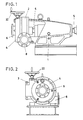
- the comminution device has a base frame 1 with a rotor housing 2 which is arranged on the side and is supported by it a cover 4 pivotable about a vertical axis 3 can be closed.
- a rotor shaft 5 is supported in shaft bearings (not specified).
- the cover 4 of the rotor housing 2 has a pipe socket 6 for the entry of the products to be shredded.
- the comminuted materials enter a collecting duct 7, which continues into an outlet pipe socket 8 oriented tangentially to the rotor housing 2.
- a disk-shaped rotor support 9 is wedged onto the rotor shaft 5 in a rotationally fixed manner.
- This receives a rotor ring 12 consisting of an inner and an outer rotor ring 10, 11.
- the outer rotor ring 11 is set back to a certain extent with respect to the inner rotor ring 10 and is arranged concentrically to the latter.
- the end of the rotor shaft 5 projecting beyond the inner rotor ring 10 carries a conical preliminary stage 13, which is opposite a hollow cone sleeve 14 arranged on the cover 4. The latter extends concentrically to the axis of the pipe socket 6.
- the cover 4 is also a carrier of a stator ring 15, which is composed of an inner and outer stator ring 16, 17.
- the inner and outer stator rings 16, 17 are arranged offset to one another in the axial direction on a support disk 18 of the cover 4.
- the latter continues in a threaded bushing 19 on which a nut 20 runs.
- a gearwheel 21 engages in the external toothing.
- the latter can be rotated by means of a handwheel 22, so that the grinding gap x existing between the rotor ring 12 and the stator ring 15 can be varied in this way.
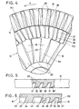
- the inner rotor ring 10 in the region of the inner rotor stage R 1 has flow channels 23 arranged in the same circumferential distribution and forming teeth 24 between them.
- Their flanks 25 facing the direction of travel y are undercut against the direction of travel y of the rotor.
- the extension of these flanks 25 lies off-center of the rotor axis of rotation.
- the flow channels 23 expand from the inside to the outside. 10 illustrates that the base 23 'of the rotor channels 23 is arched and opens at the level of the grinding gap x.
- This rotor stage R 2 is also equipped with rotor channels 26 which form teeth 27 whose flanks 28 are undercut.
- the extension of these flanks 28 points to the opposite side of the rotor axis of rotation.
- the tooth surfaces of these teeth 27 have an undercut 27 ', which can be seen in particular in FIG. 6.
- the bottom 26 'of the rotor grooves 26 extends from the grinding gap x, extends arched up to approximately the middle of the inner rotor ring 10 and opens there at the level of the end face of the outer rotor ring 11 which faces the grinding gap x.
- the latter is equipped with radially directed flow channels 29 which between leave the teeth 30.
- Their flanks 31 facing the direction of travel y are also undercut against the direction of travel of the rotor.
- the tooth surface has an undercut 30 '. In all three teeth 24, 27, 30 lying one behind the other in the radial direction, the undercut is achieved by appropriately inclined flow channels.
- the bottom 29 'of the flow channels 29 is arched in its end region and runs out at the level of the grinding gap x.
- the inner stator ring 16 extends from its end face facing the grinding gap x against flow channels 32 arranged in the same circumferential distribution, which leave teeth 33 between them.
- Their flanks 35 are also undercut, by appropriate incorporation of the throughflow channels 32.
- the flanks 35 of the teeth are also extended off-center of the rotor axis. However, the flanks 35 lie at a different angle to the rotor axis than the flanks 25 of the teeth 24 of the first rotor stage R 1.
- the teeth 33 extend on the first stator stage S 1.
- the bottom 32 'of the stator channels 32 is curved in the outward direction and ends at Scope of the stator ring 16 at the height of the grinding gap x.
- the teeth 33 have undercuts 36.
- the outer stator ring 17 encompassing the inner stator ring 16 contains a middle stator stage S 2 and an outer stator stage S 3.
- the middle stator stage S 2 is provided with through-flow channels 37 arranged in the same circumferential distribution. These are designed to be narrower than the through-flow channels 32 and are arranged offset to the circumference thereof. Teeth 38 are formed from the throughflow channels 37, the tooth flanks 39 of which are undercut due to the inclined position of the throughflow channels 37. The extensions of the flanks 39 run eccentrically to the rotor axis.
- the bottom 37 'of these channels 37 is curved and runs out at the level of the end face facing the grinding gap x.
- the outlet end extends approximately in the middle of the opposite flow channels 29 of the outer rotor stage R 3.
- the teeth 27 of the middle rotor stage R 2 have an angle z which is equal to or less than 80 °.
- the opposite angle z 'of the teeth 38 of the middle stator stage S 2 also includes such an angle. Since the outer stator ring 17 and inner rotor ring 10 overlap one another in this area, the teeth 27, 38 are moved past one another in a cutting-like manner, so that the product passing the overlap is separated with certainty, in particular when longer fibers have to be cut through.
- the product to be shredded is entered into the pipe socket 6. It then reaches the area of the preliminary stage 13 and is directed from there in the direction of the grinding gap x between the rotor ring 12 and the stator ring 15. From there it passes through the flow channels 23, 32, 26, 37, 29 and 40 one after the other in a zigzag direction and, as a result of this, reaches centrifugal force in the collecting channel 7, from where the comminuted product flows into the outlet pipe socket 8.
- the ground material exceeds the grinding gap and is gripped by the knife-like flanks of the teeth.
- cutting takes place as with a pair of scissors, which benefits improved grinding.
- the heat development is therefore less.
- the degree of comminution can then be determined very precisely. It can be realized with the appropriate grinding gap and the quality of the teeth and flow channels up to the emulsion.
Landscapes
- Engineering & Computer Science (AREA)
- Food Science & Technology (AREA)
- Chemical & Material Sciences (AREA)
- Chemical Kinetics & Catalysis (AREA)
- Crushing And Pulverization Processes (AREA)
- Separation, Recovery Or Treatment Of Waste Materials Containing Plastics (AREA)
- Crushing And Grinding (AREA)
Priority Applications (1)
| Application Number | Priority Date | Filing Date | Title |
|---|---|---|---|
| AT84108592T ATE37300T1 (de) | 1983-08-30 | 1984-07-20 | Mehrstufige zerkleinerungsvorrichtung, insbesondere fuer plaste, polymerisate fuer die bitumenmodifizierung, ptfe- u. gummi-regenerat, schlachtabfaelle fuer tiernahrung usw. |
Applications Claiming Priority (2)
| Application Number | Priority Date | Filing Date | Title |
|---|---|---|---|
| DE3331168A DE3331168C1 (de) | 1983-08-30 | 1983-08-30 | Mehrstufige Zerkleinerungsvorrichtung,insbesondere fuer Plaste,Polymerisate fuer dieBitumenmodifizierung,PTFE- u.Gummi-Regenerat,Schlachtabfaelle fuer Tiernahrung usw. |
| DE3331168 | 1983-08-30 |
Publications (3)
| Publication Number | Publication Date |
|---|---|
| EP0135697A2 EP0135697A2 (de) | 1985-04-03 |
| EP0135697A3 EP0135697A3 (en) | 1986-10-22 |
| EP0135697B1 true EP0135697B1 (de) | 1988-09-21 |
Family
ID=6207753
Family Applications (1)
| Application Number | Title | Priority Date | Filing Date |
|---|---|---|---|
| EP84108592A Expired EP0135697B1 (de) | 1983-08-30 | 1984-07-20 | Mehrstufige Zerkleinerungsvorrichtung, insbesondere für Plaste, Polymerisate für die Bitumenmodifizierung, PTFE- u. Gummi-Regenerat, Schlachtabfälle für Tiernahrung usw |
Country Status (4)
| Country | Link |
|---|---|
| EP (1) | EP0135697B1 (esLanguage) |
| JP (1) | JPS6071050A (esLanguage) |
| AT (1) | ATE37300T1 (esLanguage) |
| DE (2) | DE3331168C1 (esLanguage) |
Cited By (1)
| Publication number | Priority date | Publication date | Assignee | Title |
|---|---|---|---|---|
| EP1939239A1 (en) | 2004-01-30 | 2008-07-02 | General Electric Company | Method of preparing a poly(arylene ether) |
Families Citing this family (20)
| Publication number | Priority date | Publication date | Assignee | Title |
|---|---|---|---|---|
| DE3432255C2 (de) * | 1984-09-01 | 1986-07-17 | Wilhelm Siefer GmbH & Co KG, 5620 Velbert | Mehrstufige Zerkleinerungsvorrichtung, insbesondere für schwer reißbare Plastikfolien, Gummiregenerate oder dergleichen |
| DE4240073A1 (de) * | 1992-11-28 | 1994-06-23 | Harald Dipl Ing Suese | Vorrichtung zur thermostabilen umweltfreundlichen Direkterfassung und -verarbeitung anfallender Schlacht- und Gerbereiabfälle (TUMDASUGA) |
| US5509610A (en) * | 1994-01-27 | 1996-04-23 | Gibbco, Inc. | Centrifugal chopping and grinding apparatus |
| US5467931A (en) * | 1994-02-22 | 1995-11-21 | Beloit Technologies, Inc. | Long life refiner disc |
| RU2140358C1 (ru) * | 1998-04-28 | 1999-10-27 | Леонов Игорь Владимирович | Способ измельчения изношенных шин и устройство для его осуществления |
| FR2831838B1 (fr) * | 2001-11-06 | 2004-11-26 | Phenix Ind | Broyeur centrifuge |
| JP3651848B2 (ja) * | 2002-01-25 | 2005-05-25 | 株式会社田中住建 | 被粉砕物定量供給機能を有する碾臼 |
| WO2004078354A1 (ja) * | 2003-03-04 | 2004-09-16 | Sigma Seiki Co. Ltd. | 粉砕機 |
| US7374659B1 (en) | 2004-06-22 | 2008-05-20 | Asphalt Technology, Llc. | Methods and systems for modifying asphalts |
| RU2262384C1 (ru) * | 2004-07-21 | 2005-10-20 | Открытое Акционерное Общество "Канский Машиностроительный завод "Сегмент" | Размалывающая гарнитура дисковой мельницы |
| RU2270723C1 (ru) * | 2004-09-22 | 2006-02-27 | Открытое Акционерное Общество "Канский Машиностроительный завод "Сегмент" | Размалывающая гарнитура дисковой мельницы |
| RU2274491C1 (ru) * | 2004-12-07 | 2006-04-20 | Открытое Акционерное Общество "Канский Машиностроительный завод "Сегмент" | Размалывающая гарнитура дисковой мельницы |
| RU2270722C1 (ru) * | 2005-06-14 | 2006-02-27 | Открытое Акционерное Общество "Канский Машиностроительный завод "Сегмент" | Размалывающая гарнитура дисковой мельницы |
| RU2299807C2 (ru) * | 2005-07-22 | 2007-05-27 | Борис Александрович Куцемелов | Установка дробления шин |
| RU2288037C1 (ru) * | 2005-08-25 | 2006-11-27 | Открытое Акционерное Общество "Канский Машиностроительный завод "Сегмент" | Размалывающая гарнитура дисковой мельницы |
| RU2288038C1 (ru) * | 2005-08-25 | 2006-11-27 | Открытое Акционерное Общество "Канский Машиностроительный завод "Сегмент" | Размалывающая гарнитура дисковой мельницы |
| US7906011B2 (en) * | 2008-06-13 | 2011-03-15 | Asphalt Technology Llc | Methods and systems for manufacturing modified asphalts |
| JP4859969B2 (ja) * | 2009-09-11 | 2012-01-25 | 株式会社奈良機械製作所 | 粉粒体の解砕整粒装置 |
| US10654044B2 (en) | 2015-09-16 | 2020-05-19 | Paul J. Aitken | Cyclonic shear plates and method |
| CN116764753B (zh) * | 2023-03-31 | 2024-07-16 | 东莞市琅菱机械有限公司 | 一种涡轮传动式纳米砂磨机 |
Family Cites Families (6)
| Publication number | Priority date | Publication date | Assignee | Title |
|---|---|---|---|---|
| FR415795A (fr) * | 1910-05-11 | 1910-10-04 | Jaspers Geb | Meule artificielle |
| CH119699A (de) * | 1926-06-16 | 1927-04-01 | H Josephy | Mahlscheibenpaar mit ebenen Mahlflächen. |
| DE654360C (de) * | 1936-10-03 | 1937-12-17 | Hermann Mandl | Muehlstein |
| US2654295A (en) * | 1951-05-02 | 1953-10-06 | Sutherland Refiner Corp | Refiner apparatus |
| DE1090937B (de) * | 1956-07-11 | 1960-10-13 | Eirich Wilhelm | Rippenscheibenmuehle |
| DE7819825U1 (de) * | 1978-07-01 | 1980-02-21 | Fa. Wilhelm Siefer, 5620 Velbert | Maschine zum zerkleinern von insbesondere tierfuetterungsprodukten |
-
1983
- 1983-08-30 DE DE3331168A patent/DE3331168C1/de not_active Expired
-
1984
- 1984-07-20 EP EP84108592A patent/EP0135697B1/de not_active Expired
- 1984-07-20 AT AT84108592T patent/ATE37300T1/de not_active IP Right Cessation
- 1984-07-20 DE DE8484108592T patent/DE3474113D1/de not_active Expired
- 1984-08-30 JP JP59179531A patent/JPS6071050A/ja active Granted
Cited By (2)
| Publication number | Priority date | Publication date | Assignee | Title |
|---|---|---|---|---|
| EP1939239A1 (en) | 2004-01-30 | 2008-07-02 | General Electric Company | Method of preparing a poly(arylene ether) |
| US7459520B2 (en) | 2004-01-30 | 2008-12-02 | Sabic Innovative Plastics Ip B.V. | Poly(arylene ether) and an apparatus for producing the same |
Also Published As
| Publication number | Publication date |
|---|---|
| ATE37300T1 (de) | 1988-10-15 |
| JPH0378140B2 (esLanguage) | 1991-12-12 |
| JPS6071050A (ja) | 1985-04-22 |
| DE3331168C1 (de) | 1985-04-18 |
| DE3474113D1 (en) | 1988-10-27 |
| EP0135697A2 (de) | 1985-04-03 |
| EP0135697A3 (en) | 1986-10-22 |
Similar Documents
| Publication | Publication Date | Title |
|---|---|---|
| EP0135697B1 (de) | Mehrstufige Zerkleinerungsvorrichtung, insbesondere für Plaste, Polymerisate für die Bitumenmodifizierung, PTFE- u. Gummi-Regenerat, Schlachtabfälle für Tiernahrung usw | |
| EP0945172A1 (de) | Zerkleinerungs- und Zuteilungsvorrichtung für zerstückelbare, pumpbare Stoffe | |
| DE2517131C2 (de) | Vorrichtung zum Auflockern von feuchten, faserhaltigen Materialien | |
| EP3670920B1 (de) | Ansaugvorrichtung für eine abwasser-tauchpumpe | |
| DE3342304C2 (de) | Vorrichtung für die Herstellung von Emulsionen | |
| DE2005252C3 (de) | Abfall-Zerkleinerungsvorrichtung | |
| WO1998028077A1 (de) | Zerkleinerungsmaschine mit einem emulgator | |
| CH630538A5 (de) | Zerkleinerungsmaschine. | |
| DE2740074A1 (de) | Vorrichtung zur aufbereitung von fasermaterial | |
| CH441736A (de) | Verfahren und Vorrichtung zum kontinuierlichen Regenerieren von vulkanisierten, vorzerkleinerten Gummiabfällen | |
| DE2612692B2 (de) | Feldhäcksler | |
| DE2809609A1 (de) | Schneidsatz fuer fleischwoelfe | |
| DE4213608A1 (de) | Verfahren und vorrichtung zum zerkleinern von gummibrocken | |
| DE112015004361T5 (de) | Perforierter Rotationsschneider | |
| DE2817290C3 (de) | Radialgebläse mit Zerkleinerungsvorrichtung | |
| DE1806612A1 (de) | Verfahren und Vorrichtung zur Herstellung von Faserstoff | |
| DE3432255C2 (de) | Mehrstufige Zerkleinerungsvorrichtung, insbesondere für schwer reißbare Plastikfolien, Gummiregenerate oder dergleichen | |
| EP0114217B1 (de) | Vorrichtung zum Fördern, Zerkleinern und Mischen von Fördergut mit hohem Feststoffgehalt | |
| DE3444912C2 (de) | Vorrichtung zum Behandeln pumpfähiger Materialien | |
| DE2153236A1 (de) | Muehle | |
| DE102013206275A1 (de) | Verfahren und Vorrichtung zum Zerkleinern | |
| DE3141347A1 (de) | Strohschnitzelvorrichtung | |
| LU102840B1 (de) | Schneidring für mit Feststoff belastete Flüssigkeit einer Pumpe | |
| DE3247303A1 (de) | Einrichtung zur zerkleinerung und gleichzeitigen trocknung von waermeempfindlichem gut | |
| DE3009233C2 (de) | Mischvorrichtung |
Legal Events
| Date | Code | Title | Description |
|---|---|---|---|
| PUAI | Public reference made under article 153(3) epc to a published international application that has entered the european phase |
Free format text: ORIGINAL CODE: 0009012 |
|
| AK | Designated contracting states |
Designated state(s): AT BE CH DE FR GB IT LI LU NL SE |
|
| PUAL | Search report despatched |
Free format text: ORIGINAL CODE: 0009013 |
|
| AK | Designated contracting states |
Kind code of ref document: A3 Designated state(s): AT BE CH DE FR GB IT LI LU NL SE |
|
| 17P | Request for examination filed |
Effective date: 19870102 |
|
| 17Q | First examination report despatched |
Effective date: 19880209 |
|
| GRAA | (expected) grant |
Free format text: ORIGINAL CODE: 0009210 |
|
| AK | Designated contracting states |
Kind code of ref document: B1 Designated state(s): AT BE CH DE FR GB IT LI LU NL SE |
|
| REF | Corresponds to: |
Ref document number: 37300 Country of ref document: AT Date of ref document: 19881015 Kind code of ref document: T |
|
| REF | Corresponds to: |
Ref document number: 3474113 Country of ref document: DE Date of ref document: 19881027 |
|
| ET | Fr: translation filed | ||
| GBT | Gb: translation of ep patent filed (gb section 77(6)(a)/1977) | ||
| ITF | It: translation for a ep patent filed | ||
| PLBE | No opposition filed within time limit |
Free format text: ORIGINAL CODE: 0009261 |
|
| STAA | Information on the status of an ep patent application or granted ep patent |
Free format text: STATUS: NO OPPOSITION FILED WITHIN TIME LIMIT |
|
| 26N | No opposition filed | ||
| ITTA | It: last paid annual fee | ||
| EPTA | Lu: last paid annual fee | ||
| EAL | Se: european patent in force in sweden |
Ref document number: 84108592.1 |
|
| PGFP | Annual fee paid to national office [announced via postgrant information from national office to epo] |
Ref country code: BE Payment date: 20000619 Year of fee payment: 17 Ref country code: AT Payment date: 20000619 Year of fee payment: 17 |
|
| PGFP | Annual fee paid to national office [announced via postgrant information from national office to epo] |
Ref country code: SE Payment date: 20000620 Year of fee payment: 17 Ref country code: NL Payment date: 20000620 Year of fee payment: 17 Ref country code: LU Payment date: 20000620 Year of fee payment: 17 Ref country code: FR Payment date: 20000620 Year of fee payment: 17 Ref country code: CH Payment date: 20000620 Year of fee payment: 17 |
|
| PGFP | Annual fee paid to national office [announced via postgrant information from national office to epo] |
Ref country code: GB Payment date: 20000621 Year of fee payment: 17 |
|
| PGFP | Annual fee paid to national office [announced via postgrant information from national office to epo] |
Ref country code: DE Payment date: 20000703 Year of fee payment: 17 |
|
| PG25 | Lapsed in a contracting state [announced via postgrant information from national office to epo] |
Ref country code: LU Free format text: LAPSE BECAUSE OF NON-PAYMENT OF DUE FEES Effective date: 20010720 Ref country code: GB Free format text: LAPSE BECAUSE OF NON-PAYMENT OF DUE FEES Effective date: 20010720 Ref country code: AT Free format text: LAPSE BECAUSE OF NON-PAYMENT OF DUE FEES Effective date: 20010720 |
|
| PG25 | Lapsed in a contracting state [announced via postgrant information from national office to epo] |
Ref country code: SE Free format text: LAPSE BECAUSE OF NON-PAYMENT OF DUE FEES Effective date: 20010721 |
|
| PG25 | Lapsed in a contracting state [announced via postgrant information from national office to epo] |
Ref country code: LI Free format text: LAPSE BECAUSE OF NON-PAYMENT OF DUE FEES Effective date: 20010731 Ref country code: CH Free format text: LAPSE BECAUSE OF NON-PAYMENT OF DUE FEES Effective date: 20010731 Ref country code: BE Free format text: LAPSE BECAUSE OF NON-PAYMENT OF DUE FEES Effective date: 20010731 |
|
| BERE | Be: lapsed |
Owner name: WILHELM SIEFER G.M.B.H. & CO. K.G. Effective date: 20010731 |
|
| PG25 | Lapsed in a contracting state [announced via postgrant information from national office to epo] |
Ref country code: NL Free format text: LAPSE BECAUSE OF NON-PAYMENT OF DUE FEES Effective date: 20020201 |
|
| EUG | Se: european patent has lapsed |
Ref document number: 84108592.1 |
|
| GBPC | Gb: european patent ceased through non-payment of renewal fee |
Effective date: 20010720 |
|
| REG | Reference to a national code |
Ref country code: CH Ref legal event code: PL |
|
| PG25 | Lapsed in a contracting state [announced via postgrant information from national office to epo] |
Ref country code: FR Free format text: LAPSE BECAUSE OF NON-PAYMENT OF DUE FEES Effective date: 20020329 |
|
| NLV4 | Nl: lapsed or anulled due to non-payment of the annual fee |
Effective date: 20020201 |
|
| PG25 | Lapsed in a contracting state [announced via postgrant information from national office to epo] |
Ref country code: DE Free format text: LAPSE BECAUSE OF NON-PAYMENT OF DUE FEES Effective date: 20020501 |
|
| REG | Reference to a national code |
Ref country code: FR Ref legal event code: ST |