EP0106332B1 - Convoyeur accumulateur pour marchandises en ballot avec écluse de sortie - Google Patents
Convoyeur accumulateur pour marchandises en ballot avec écluse de sortie Download PDFInfo
- Publication number
- EP0106332B1 EP0106332B1 EP83110257A EP83110257A EP0106332B1 EP 0106332 B1 EP0106332 B1 EP 0106332B1 EP 83110257 A EP83110257 A EP 83110257A EP 83110257 A EP83110257 A EP 83110257A EP 0106332 B1 EP0106332 B1 EP 0106332B1
- Authority
- EP
- European Patent Office
- Prior art keywords
- section
- intermediate roller
- conveyor
- sensor
- section frame
- Prior art date
- Legal status (The legal status is an assumption and is not a legal conclusion. Google has not performed a legal analysis and makes no representation as to the accuracy of the status listed.)
- Expired
Links
- 230000000994 depressogenic effect Effects 0.000 claims description 3
- 230000000979 retarding effect Effects 0.000 abstract 2
- 238000009825 accumulation Methods 0.000 description 15
- 238000007599 discharging Methods 0.000 description 2
- 230000004888 barrier function Effects 0.000 description 1
- 230000007257 malfunction Effects 0.000 description 1
- 238000000926 separation method Methods 0.000 description 1
Images


Classifications
-
- B—PERFORMING OPERATIONS; TRANSPORTING
- B65—CONVEYING; PACKING; STORING; HANDLING THIN OR FILAMENTARY MATERIAL
- B65G—TRANSPORT OR STORAGE DEVICES, e.g. CONVEYORS FOR LOADING OR TIPPING, SHOP CONVEYOR SYSTEMS OR PNEUMATIC TUBE CONVEYORS
- B65G47/00—Article or material-handling devices associated with conveyors; Methods employing such devices
- B65G47/22—Devices influencing the relative position or the attitude of articles during transit by conveyors
- B65G47/26—Devices influencing the relative position or the attitude of articles during transit by conveyors arranging the articles, e.g. varying spacing between individual articles
- B65G47/261—Accumulating articles
- B65G47/268—Accumulating articles by means of belt or chain conveyor
-
- B—PERFORMING OPERATIONS; TRANSPORTING
- B65—CONVEYING; PACKING; STORING; HANDLING THIN OR FILAMENTARY MATERIAL
- B65G—TRANSPORT OR STORAGE DEVICES, e.g. CONVEYORS FOR LOADING OR TIPPING, SHOP CONVEYOR SYSTEMS OR PNEUMATIC TUBE CONVEYORS
- B65G47/00—Article or material-handling devices associated with conveyors; Methods employing such devices
- B65G47/22—Devices influencing the relative position or the attitude of articles during transit by conveyors
- B65G47/26—Devices influencing the relative position or the attitude of articles during transit by conveyors arranging the articles, e.g. varying spacing between individual articles
- B65G47/261—Accumulating articles
Definitions
- the invention relates to a storage conveyor for piece goods with a discharge station at at least one point and with a sectioned, drivable and carrying the piece goods transport means, each section being driven by an intermediate roller driven by a continuously rotating traction means, which protrudes into the movement path of the piece goods Sensor is adjustable from a drive position to a free-wheel position.
- a accumulation conveyor for general cargo of the type mentioned is already known. With this, the piece goods are transported along the accumulation conveyor and can possibly be discharged to one side by means of special removal stations. As a separate unit, each removal station not only requires technical effort, but also its own route area, which cannot be used as storage space.
- a conveyor belt switch is also known, in which at the end of a conveyor a device with a foldable about a horizontal axis conveyor belt is provided, through which the piece goods can be transferred either to an upper or a lower further conveyor.
- This turnout conveyor has its own drive and is a continuously working device that is not suitable for traffic jams. This device also requires its own space, which cannot be used as storage space.
- EP-A-59 984 also discloses a discharge device in a conveyor track, in which a part of the transport means is mounted in a discharge flap which can be swiveled upwards or downwards about a horizontal axis.
- the pivot axis of the discharge flap is coaxial with the axis of the first idler roller at the inlet end of the discharge flap.
- the known piece goods conveyors with a discharge station can therefore either not work as accumulation conveyors or require route areas that cannot be used as storage space for discharge.
- the object of the invention is therefore to create a accumulation conveyor with a large accumulation volume and a large number of discharge stations, through which the discharge takes place at high speed.
- a section of the transport means is mounted as a discharge station in a section frame which can be folded about a folding axis arranged parallel to the transport plane and perpendicular to the conveying direction, the intermediate roller is arranged at the inlet end of the section on the section frame and approximately coaxially to the folding axis and the intermediate roller is in constant engagement with the traction device regardless of the position of the section frame.
- the advantages achieved by the invention are, in particular, that both the entire length of the accumulation conveyor is used for accumulating piece goods, and that each station can be designed simultaneously as a discharge station.
- the storage volume therefore corresponds to that of a normal storage conveyor with the possibility of being discharged at any storage location.
- the discharge station therefore does not require its own space, so that the entire conveyor length can be used as storage space as before with an accumulation-only conveyor.
- the swiveling-out movement required for discharging can be carried out so briefly that the transport on the accumulation conveyor can take place at the usual speed.
- the accumulation conveyor according to the invention therefore combines the function of accumulation with that of discharging, without requiring an increased space.
- the accumulation conveyor therefore fulfills the congestion and distribution task at the same time.
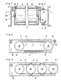
- the accumulation conveyor has, between parallel longitudinal frames 1 and 1 ', a means of transport 2 in the form of a conveyor belt, of transport chains or the like or of idlers.
- the transport means 2 is subdivided into a plurality of sections 5, 5 ′, 5 ′′, one behind the other, each of which can be driven independently of one another by a rotating traction means 4, in particular a chain, by means of an intermediate roller 14.
- the traction means 4 is driven by a motor (not shown) in FIG 1 driven from left to right.
- Each section 5, 5 ', 5 is mounted in a section frame 6, in which deflection rollers 7 are rotatably arranged at both ends, which are wrapped by the belt-shaped transport means 2. Between the deflection rollers 7, depending on the design of the transport means 2, there is support 8 for receiving the compressive force generated by the piece goods to be transported, assuming a transport direction pointing from left to right according to arrow 9, the section frame 6 is at the left end opposite to the transport direction 9 a folding axis 10 articulated to the longitudinal frame 1 and 1 'and can be folded up and / or down from the transport plane of the accumulation conveyor, as indicated by dash-dotted lines in FIG.
- distribution tracks 11 and 11' which lead directly or indirectly to a specific destination and can be of any design however, it is driven at least in the takeover area from section 5, 5 ', 5 ". It can be seen that a piece of goods transported on the transport means 2 can optionally be discharged upwards or downwards by folding one of the sections 5, 5 ', 5 "which act as a discharge station and can be directed to a predetermined destination.
- the axis 12' is a shaft guided through the section frame formed, which carries a drive wheel 13 on the outside, which in the exemplary embodiment is designed as a gear wheel.
- a corresponding counter wheel 14 'of an intermediate roller 14 is in drive connection in its drive position with this drive wheel 13.
- the counter wheel 14' is rigidly connected to a drive wheel 14 "and with this is rotatably mounted in a housing 15.
- the latter is mounted approximately vertically above the axis of rotation of the counter wheel 14 'oscillating about a pivot axis 16 fastened to the frame 6, so that the intermediate roller 14 can be pivoted clockwise from the illustrated drive position into a freewheel position in which the counter wheel 14' is disengaged from the drive wheel 13 is.
- the drive wheel 14 " is driven by the traction means 4 and preferably remains in constant drive connection with it.
- the drive wheel 14" is correspondingly designed as a chain wheel, which constantly, that is also in the freewheeling position, into the chain of the traction means 4 intervenes.
- support profiles 17 fastened to the longitudinal frame 1 are provided.
- e.g. sensor 18 designed as a roller, which is mounted on both sides on sensor levers 19, which can pivot about axes 20 attached to the output-side end of the frame 6 perpendicular to the transport plane of the piece goods on the transport means 2.
- the sensor 18 normally protrudes into the transport plane of the piece goods and can be pressed downwards into an outside switching position, as is indicated by dash-dotted lines in FIG. 4. In this switching position, the axis 18 'of the sensor 18 lies on a stop 21 of the section frame 6 and thus serves as a support for the piece goods sliding over it.
- the feeler lever 19 located on the side of the intermediate roller 14 has a downwardly projecting arm 19 ', to which a switching rod 23 is articulated at the bottom through an elongated hole 22 and which is articulated with its other, upwardly angled end 23' at the upper end of a double lever 24 connected.
- the latter is pivotally mounted coaxially to the axis of the counter wheel 14 'on the housing 15 of the intermediate roller 14 of the same section 5, 5', 5 ".
- a shift linkage 25 is articulated, which has its other end on the arm 19 'of the Sensor lever 19 of the section 5, 5 ', 5 "lying in front of it in the transport direction is connected.
- the shift linkage 25 is in two parts and is equipped with a joint 26 at the separation point, which is arranged approximately coaxially to the folding axis 10 on a holding arm 27. This is articulated on an actuating arm 28 carrying the folding axis 10, which bridges the intermediate roller 14 at the top and is fastened to the section frame 6.
- a roof-shaped, downwardly projecting stop 32 is provided at the lower end of the extension 28 ', against which adjusting wedges 33 and 33' rest on both sides in the transport position, which are supported by an auxiliary force, e.g. Actuating cylinder, can be adjusted downward from the illustrated locking position into a release position, so that the section frame 6 can be folded in one direction or the other, as indicated by dash-dotted lines.
- the piece goods are transported on the means of transport 2, the piece goods are stopped piece by piece by switching off the respective section 5, 5 ', 5 "in the event of a traffic jam or a safety device. If a sensor 18 is depressed for this reason, then the shift linkage 25 is used the double lever 24 of the intermediate roller 14 adjusts the section 5, 5 'or 5 "lying in the opposite direction to the transport direction in a clockwise direction, so that the elongated hole 22 reaches its other end position by shifting the shift rod 23 to the right. If the sensor 18 of this section 5, 5 ', 5 "is now also depressed, the shift rod 23 is pressed clockwise by the switching movement and, because the shift linkage 25 remains stationary, the intermediate roller 14 is turned clockwise into the freewheeling position.
- a reading station 35 is arranged above or next to it, by means of which the coding applied to the piece goods is read, preferably independently of the respective angular position to the direction of transport.
- the result is assigned to the associated section 5 , 5 ', 5 “transferred, in particular to the following in the direction of transport 9, so that the connected section 5, 5', 5" is folded up or down when the further transport begins, if the coding applies, in order to discharge the piece goods in question Leaving section 5, 5 ', 5 "can additionally be monitored by a light barrier 34 attached to the output end, so that the section frame 6 is folded as briefly as possible in order to achieve a speedy transport of general cargo at the usual speed.
- the transport means 2 can also be used as a chain conveyor.
- Fig. 8 be formed, in which the chains 2 'carrying the piece goods are guided over appropriately mounted supports 8.
- the transport means 2 can also consist of several support rollers 2 ", which are driven, for example, by a common, rotating traction means, such as a chain or V-belt, when the intermediate roller 14, not shown, is in the drive position.
Landscapes
- Engineering & Computer Science (AREA)
- Mechanical Engineering (AREA)
- Rollers For Roller Conveyors For Transfer (AREA)
- Threshing Machine Elements (AREA)
- Branching, Merging, And Special Transfer Between Conveyors (AREA)
- Framework For Endless Conveyors (AREA)
- Vending Machines For Individual Products (AREA)
- Attitude Control For Articles On Conveyors (AREA)
Claims (3)
Priority Applications (1)
| Application Number | Priority Date | Filing Date | Title |
|---|---|---|---|
| AT83110257T ATE34550T1 (de) | 1982-10-18 | 1983-10-14 | Staufoerderer fuer stueckgut mit ausschleusstation. |
Applications Claiming Priority (2)
| Application Number | Priority Date | Filing Date | Title |
|---|---|---|---|
| DE3238511 | 1982-10-18 | ||
| DE3238511A DE3238511C1 (de) | 1982-10-18 | 1982-10-18 | Staufoerderer fuer Stueckgut mit Ausschleusstation |
Publications (2)
| Publication Number | Publication Date |
|---|---|
| EP0106332A1 EP0106332A1 (fr) | 1984-04-25 |
| EP0106332B1 true EP0106332B1 (fr) | 1988-05-25 |
Family
ID=6175969
Family Applications (1)
| Application Number | Title | Priority Date | Filing Date |
|---|---|---|---|
| EP83110257A Expired EP0106332B1 (fr) | 1982-10-18 | 1983-10-14 | Convoyeur accumulateur pour marchandises en ballot avec écluse de sortie |
Country Status (5)
| Country | Link |
|---|---|
| US (1) | US4598814A (fr) |
| EP (1) | EP0106332B1 (fr) |
| AT (1) | ATE34550T1 (fr) |
| AU (1) | AU573192B2 (fr) |
| DE (2) | DE3238511C1 (fr) |
Families Citing this family (6)
| Publication number | Priority date | Publication date | Assignee | Title |
|---|---|---|---|---|
| US4938336A (en) * | 1985-09-04 | 1990-07-03 | Nabisco Brands, Inc. | Selective ejection conveyor |
| US4809842A (en) * | 1985-09-04 | 1989-03-07 | Nabisco Brands, Inc. | Selective ejection conveyor |
| US4733768A (en) * | 1985-09-04 | 1988-03-29 | Agostino Aquino | Selective ejection conveyors |
| IT1213829B (it) * | 1987-09-22 | 1990-01-05 | Solis Srl | Metodo e macchina per il trasferimento automatico dei collant o simili manufatti tubolari tra due gruppi di macchine rifinitrici di detti manufatti |
| US4860973A (en) * | 1988-04-27 | 1989-08-29 | The Boeing Company | Cargo conveying system |
| US6550603B1 (en) | 2000-08-23 | 2003-04-22 | Lockheed Martin Corporation | Rotating belt diverter |
Family Cites Families (8)
| Publication number | Priority date | Publication date | Assignee | Title |
|---|---|---|---|---|
| US1809456A (en) * | 1928-03-21 | 1931-06-09 | Streeter Edwin Henry | Transfer device |
| AT162724B (de) * | 1947-01-09 | 1949-04-11 | Heid Ag Maschf | Aus Einzelgliedern bestehender Bandförderer |
| US2883033A (en) * | 1953-05-21 | 1959-04-21 | Baker Perkins Inc | Conveyor system |
| US3513960A (en) * | 1968-01-17 | 1970-05-26 | Gifford Wood Inc | Accumulator conveyor |
| US4011935A (en) * | 1975-09-08 | 1977-03-15 | Massey John P | Sorting machines |
| DE2853483C2 (de) * | 1978-12-12 | 1985-08-29 | geb. Kramer Elfriede 6920 Sinsheim Gebhardt | Stauförderer für Stückgut |
| DE8017695U1 (de) * | 1980-06-28 | 1980-10-16 | H. Wohlenberg Kg-Gmbh & Co, 3000 Hannover | Transportbandweiche |
| DE3109174A1 (de) * | 1981-03-11 | 1982-10-14 | Gebhardt Fördertechnik GmbH, 6920 Sinsheim | Ausschleusvorrichtung fuer eine foerderbahn |
-
1982
- 1982-10-18 DE DE3238511A patent/DE3238511C1/de not_active Expired
-
1983
- 1983-10-14 EP EP83110257A patent/EP0106332B1/fr not_active Expired
- 1983-10-14 DE DE8383110257T patent/DE3376745D1/de not_active Expired
- 1983-10-14 AT AT83110257T patent/ATE34550T1/de not_active IP Right Cessation
- 1983-11-17 AU AU21445/83A patent/AU573192B2/en not_active Ceased
- 1983-11-29 US US06/556,120 patent/US4598814A/en not_active Expired - Lifetime
Also Published As
| Publication number | Publication date |
|---|---|
| AU2144583A (en) | 1985-05-23 |
| DE3238511C1 (de) | 1984-02-16 |
| ATE34550T1 (de) | 1988-06-15 |
| US4598814A (en) | 1986-07-08 |
| DE3376745D1 (en) | 1988-06-30 |
| AU573192B2 (en) | 1988-06-02 |
| EP0106332A1 (fr) | 1984-04-25 |
Similar Documents
| Publication | Publication Date | Title |
|---|---|---|
| DE4343036C2 (de) | Transportsystem mit elektrischen Förder-Schienenfahrzeugen | |
| EP0114343A1 (fr) | Appareil combiné de distribution pour marchandises | |
| EP0085886B1 (fr) | Convoyeur réversible à accumulation | |
| EP0059984B1 (fr) | Dispositif de distribution pour un convoyeur | |
| AT394530B (de) | Schuettgutverladewagen | |
| DE3241559C1 (de) | Vorrichtung zum Reinigen der Raeder,insbesondere der Felgen,eines Fahrzeuges in einer Waschstrasse | |
| DE2127310C3 (de) | Fördereinrichtung für Flaschen oder ähnliches Fördergut | |
| DE2853483A1 (de) | Staufoerderer fuer stueckgut | |
| DE2552360C2 (de) | Werkstückelevator | |
| DE2355143C3 (de) | Paletten-Umsetzvorrichtung | |
| DE3504365A1 (de) | Verteilervorrichtung fuer stueckgut | |
| DE2259273C2 (de) | Vorrichtung zum Ausschleusen von Stückgut aus einer Rollenbahn | |
| DE3238511C1 (de) | Staufoerderer fuer Stueckgut mit Ausschleusstation | |
| DE1173831B (de) | Zigaretten-Beschickungsanlage an Zigaretten-Packmaschinen | |
| CH402731A (de) | Fördereinrichtung | |
| DE1289778B (de) | Roellchenbahnweiche | |
| DE4428247A1 (de) | Transportvorrichtung für textile Packungen | |
| DE2332808C2 (de) | Vorrichtung zum Umsetzen von Stückgut von einer Rollenbahn | |
| DE19513422C2 (de) | Staurollenbahn | |
| DD212237A5 (de) | Staufoerderer fuer stueckgut mit ausschleusstation | |
| DE2640032A1 (de) | Vorrichtung zum gruppenweisen abtrennen einer vorbestimmten anzahl von schuppenartig sich ueberdeckenden gegenstaenden | |
| DE2922147C2 (de) | Wendevorrichtung mit als Ganzes ausmachender Hub- oder Senkvorrichtung | |
| DE594037C (fr) | ||
| DE907517C (de) | Praezisionsfoerdereinrichtung mittels Schraubenspindeln, insbesondere fuer Pruef- und Messzwecke | |
| DE3321108A1 (de) | Ablaeng- und stapelvorrichtung fuer langgestrecktes gut |
Legal Events
| Date | Code | Title | Description |
|---|---|---|---|
| PUAI | Public reference made under article 153(3) epc to a published international application that has entered the european phase |
Free format text: ORIGINAL CODE: 0009012 |
|
| AK | Designated contracting states |
Designated state(s): AT BE CH DE FR GB IT LI NL SE |
|
| 17P | Request for examination filed |
Effective date: 19840627 |
|
| 18R | Application refused |
Effective date: 19870515 |
|
| 18RA | Request filed for re-establishment of rights before grant |
Effective date: 19871001 |
|
| D18R | Application refused (deleted) | ||
| GRAA | (expected) grant |
Free format text: ORIGINAL CODE: 0009210 |
|
| AK | Designated contracting states |
Kind code of ref document: B1 Designated state(s): AT BE CH DE FR GB IT LI NL SE |
|
| REF | Corresponds to: |
Ref document number: 34550 Country of ref document: AT Date of ref document: 19880615 Kind code of ref document: T |
|
| REF | Corresponds to: |
Ref document number: 3376745 Country of ref document: DE Date of ref document: 19880630 |
|
| ET | Fr: translation filed | ||
| ITF | It: translation for a ep patent filed | ||
| GBT | Gb: translation of ep patent filed (gb section 77(6)(a)/1977) | ||
| PLBE | No opposition filed within time limit |
Free format text: ORIGINAL CODE: 0009261 |
|
| STAA | Information on the status of an ep patent application or granted ep patent |
Free format text: STATUS: NO OPPOSITION FILED WITHIN TIME LIMIT |
|
| 26N | No opposition filed | ||
| ITTA | It: last paid annual fee | ||
| EAL | Se: european patent in force in sweden |
Ref document number: 83110257.9 |
|
| PGFP | Annual fee paid to national office [announced via postgrant information from national office to epo] |
Ref country code: GB Payment date: 20000925 Year of fee payment: 18 |
|
| PGFP | Annual fee paid to national office [announced via postgrant information from national office to epo] |
Ref country code: FR Payment date: 20001017 Year of fee payment: 18 |
|
| PGFP | Annual fee paid to national office [announced via postgrant information from national office to epo] |
Ref country code: AT Payment date: 20001019 Year of fee payment: 18 |
|
| PGFP | Annual fee paid to national office [announced via postgrant information from national office to epo] |
Ref country code: NL Payment date: 20001020 Year of fee payment: 18 Ref country code: BE Payment date: 20001020 Year of fee payment: 18 |
|
| PGFP | Annual fee paid to national office [announced via postgrant information from national office to epo] |
Ref country code: SE Payment date: 20001023 Year of fee payment: 18 |
|
| PGFP | Annual fee paid to national office [announced via postgrant information from national office to epo] |
Ref country code: CH Payment date: 20001030 Year of fee payment: 18 |
|
| PGFP | Annual fee paid to national office [announced via postgrant information from national office to epo] |
Ref country code: DE Payment date: 20001106 Year of fee payment: 18 |
|
| PG25 | Lapsed in a contracting state [announced via postgrant information from national office to epo] |
Ref country code: GB Free format text: LAPSE BECAUSE OF NON-PAYMENT OF DUE FEES Effective date: 20011014 Ref country code: AT Free format text: LAPSE BECAUSE OF NON-PAYMENT OF DUE FEES Effective date: 20011014 |
|
| PG25 | Lapsed in a contracting state [announced via postgrant information from national office to epo] |
Ref country code: SE Free format text: LAPSE BECAUSE OF NON-PAYMENT OF DUE FEES Effective date: 20011015 |
|
| PG25 | Lapsed in a contracting state [announced via postgrant information from national office to epo] |
Ref country code: LI Free format text: LAPSE BECAUSE OF NON-PAYMENT OF DUE FEES Effective date: 20011031 Ref country code: CH Free format text: LAPSE BECAUSE OF NON-PAYMENT OF DUE FEES Effective date: 20011031 Ref country code: BE Free format text: LAPSE BECAUSE OF NON-PAYMENT OF DUE FEES Effective date: 20011031 |
|
| REG | Reference to a national code |
Ref country code: GB Ref legal event code: IF02 |
|
| BERE | Be: lapsed |
Owner name: GEBHARDT FORDERTECHNIK G.M.B.H. Effective date: 20011031 |
|
| PG25 | Lapsed in a contracting state [announced via postgrant information from national office to epo] |
Ref country code: NL Free format text: LAPSE BECAUSE OF NON-PAYMENT OF DUE FEES Effective date: 20020501 |
|
| EUG | Se: european patent has lapsed |
Ref document number: 83110257.9 |
|
| GBPC | Gb: european patent ceased through non-payment of renewal fee |
Effective date: 20011014 |
|
| REG | Reference to a national code |
Ref country code: CH Ref legal event code: PL |
|
| PG25 | Lapsed in a contracting state [announced via postgrant information from national office to epo] |
Ref country code: FR Free format text: LAPSE BECAUSE OF NON-PAYMENT OF DUE FEES Effective date: 20020628 |
|
| NLV4 | Nl: lapsed or anulled due to non-payment of the annual fee |
Effective date: 20020501 |
|
| PG25 | Lapsed in a contracting state [announced via postgrant information from national office to epo] |
Ref country code: DE Free format text: LAPSE BECAUSE OF NON-PAYMENT OF DUE FEES Effective date: 20020702 |
|
| REG | Reference to a national code |
Ref country code: FR Ref legal event code: ST |