EP0104367A2 - Horde für Mälzereien und andere Gutbehandlungsräume - Google Patents
Horde für Mälzereien und andere Gutbehandlungsräume Download PDFInfo
- Publication number
- EP0104367A2 EP0104367A2 EP83107587A EP83107587A EP0104367A2 EP 0104367 A2 EP0104367 A2 EP 0104367A2 EP 83107587 A EP83107587 A EP 83107587A EP 83107587 A EP83107587 A EP 83107587A EP 0104367 A2 EP0104367 A2 EP 0104367A2
- Authority
- EP
- European Patent Office
- Prior art keywords
- profiles
- clamping
- sheet metal
- horde
- tray bottom
- Prior art date
- Legal status (The legal status is an assumption and is not a legal conclusion. Google has not performed a legal analysis and makes no representation as to the accuracy of the status listed.)
- Granted
Links
Images

Classifications
-
- C—CHEMISTRY; METALLURGY
- C12—BIOCHEMISTRY; BEER; SPIRITS; WINE; VINEGAR; MICROBIOLOGY; ENZYMOLOGY; MUTATION OR GENETIC ENGINEERING
- C12C—BEER; PREPARATION OF BEER BY FERMENTATION; PREPARATION OF MALT FOR MAKING BEER; PREPARATION OF HOPS FOR MAKING BEER
- C12C1/00—Preparation of malt
- C12C1/027—Germinating
- C12C1/0275—Germinating on single or multi-stage floors
-
- C—CHEMISTRY; METALLURGY
- C12—BIOCHEMISTRY; BEER; SPIRITS; WINE; VINEGAR; MICROBIOLOGY; ENZYMOLOGY; MUTATION OR GENETIC ENGINEERING
- C12C—BEER; PREPARATION OF BEER BY FERMENTATION; PREPARATION OF MALT FOR MAKING BEER; PREPARATION OF HOPS FOR MAKING BEER
- C12C1/00—Preparation of malt
- C12C1/02—Pretreatment of grains, e.g. washing, steeping
-
- C—CHEMISTRY; METALLURGY
- C12—BIOCHEMISTRY; BEER; SPIRITS; WINE; VINEGAR; MICROBIOLOGY; ENZYMOLOGY; MUTATION OR GENETIC ENGINEERING
- C12C—BEER; PREPARATION OF BEER BY FERMENTATION; PREPARATION OF MALT FOR MAKING BEER; PREPARATION OF HOPS FOR MAKING BEER
- C12C1/00—Preparation of malt
- C12C1/067—Drying
- C12C1/10—Drying on fixed supports
Definitions
- the invention relates to a horde for malting plants and other areas of good cultivation, with a supporting structure and a floor which is accommodated by the latter and is perforated for the passage of the good treatment medium.
- Hordes of the type in question are used for moistening, germinating and drying or drying cereals, hops and other bulk materials and are often of considerable size and have to accommodate many tons of heavy bulk material, for example in modern large malt plants. They are designed either as immovable hordes, so-called plan hordes, or as mobile hordes, for example, as tilting hordes or rotating hordes.
- hordes is a basic structure consisting of a supporting structure and a floor, whereby the supporting structure is formed from profile or truss girders and the floor taken up by the supporting structure consists only of a fine-meshed wire mesh, for example with small and simple tray units, or - in the most common version - Is composed of a plurality of frames provided with a perforated sheet covering.
- the frames which are provided with a multitude of supporting webs to support the perforated sheet covering, are made in a welded construction and require the cutting and welding of relatively many individual parts.
- the perforated sheet covering is applied to the frame by riveting or welding; the former is expensive, the latter is cheaper, but almost always requires one Messages from the frame because it has warped due to thermal stress.
- the subsequent hot-dip galvanizing usually requires a second message.
- the news is time-consuming because, with regard to the required flatness and dimensional accuracy of the frame, it must be done fairly precisely if the finished tray floor is to be flat with regard to devices to be used later on and should not have any large gaps or gaps between its frames , which harbor the risk of moldy or rotting good nests.
- the known tray construction has a high weight per m 2 tray surface due to its material-consuming and labor-intensive frame construction of its floor and is expensive due to poor material utilization. Because the tolerances with regard to height and rectangularity are difficult to comply with, and as a result a lot of communication and fitting work is required on the construction sites, the price per square meter is negatively influenced by such reworking.
- the invention has for its object to improve hordes of the type mentioned in such a way that their floor has the same load-bearing capacity and permeability for the good treatment medium, has a much smaller square meter weight and is easier and quicker to assemble than the known tray floors and message and adjustment work largely come to an end.
- the design according to the invention it is possible to assemble the tray bottom from hollow sheet metal profiles of finite length to be rolled as semifinished products, which can be cut to shorter lengths and used almost without waste if necessary, by simply placing the hollow profiles together in rows on the supporting structure and using the connecting means according to the invention by simply pressing down - similar to a push button - can be positively connected to one another.
- the new tray floor is therefore very quick to assemble, it is also characterized by a weight that is around a quarter lower than that of known trays and by inexpensive production.
- claims 2 and 3 ensure that the hollow sheet metal profiles have a spring action due to their open underside and the convergence of their flanges, which is used to connect the hollow sheet metal profiles to one another, the molded locking strips additionally securing the connection by positive locking.
- a connecting means for the hollow sheet metal profiles was created, which is inexpensive, can be handled particularly easily and not only forms a reliable connection for the hollow sheet metal profiles, but by the indentation made in some places after the laying of a leg the clamping rail allows in the simplest way to attach the latter and the sheet metal hollow profiles clamped to it on the supports of the supporting structure.
- the circular tray for example intended for germinating green malt, consists, according to FIGS. 1 and 2, of a supporting structure 1 and a floor 2.
- the supporting structure 1 is composed of horizontal girders with an I-profile and vertical supports 4, which support the supports 3 at approximately uniform intervals and stand on the floor 5 of the crop treatment room 6.
- Each of the parallel beams 3 rests with one end on a bearing block 7, which is anchored in a recess in the outer wall 8 of the malting building, and with its other end on a bearing block 9, which is in a recess in the center column 10 or in another recess the outer wall 8 is fixed.
- the bottom 2 of the horde is composed of hollow sheet metal profiles in the form of clamping profiles 11 which are U-shaped in cross section.
- the clamping profiles 11, which are supplied in finite lengths, for example 6 m in length, as semi-finished products, which can be rolled, for example, from stainless steel or zinc sheet, are arranged closely parallel to one another as rows which are transverse to their longitudinal axis on the supports 3, due to the circular cross section of the treatment room 6 or the arch shape of the outer wall 8 of the malting building are cut radially on the outside to correspondingly shorter lengths (FIG. 1). As can be seen from FIGS.
- the clamping profiles 11 are designed as U-profiles, the webs 12 of which have rows 15 of slots 15 for the passage of the germ air over the entire length of the clamping profiles 11 and their downwardly facing flanges 13, 14 converge and each have an inwardly directed locking bar 16 and 17 at their free ends.
- transverse clamping rails 18 of predetermined length, for example 1.50 m in length (FIG. 4), are placed on each support 3 and adjoin one another on the end face. which are formed as rectangular angular profiles made of sheet metal and have a horizontal leg 19 and a vertical leg 20 (Fig. 3), which stiffens the clamping rail 18 in the horizontal plane. With their leg 19, the clamping rails 18 rest on the associated carrier 3 and have 19 pairs of noses 24 of noses 21, 22 at the free end of this leg, which are directed upwards; the pairs of lugs 24 are arranged with a division 23 distributed over the length of the clamping rail 18, the division 23 being equal to the width of a clamping profile 11 (FIG. 4).
- the lugs 21, 22 of each pair of lugs 24 each have a latching notch 25 or 26 on their mutually facing sides (see the detail shown enlarged in FIG. 5, which is marked by a circle in FIG. 4). Due to the clamping effect of the flanges 14, 13 and the pressure exerted from above during assembly on the clamping profile 11, a latching bar 17 or 16 is latched into the notches 25, 26, namely, as shown in FIGS. 4 and 5, the locking bar 16 of a flange 13 of a clamping profile 11 into the locking notch 26 of a nose 22 of a pair of lugs 24 and the locking bar 1? its other flange 14 snapped into a notch 25 of the nose 21 of the adjacent pair of noses 24.
- clamping profiles 11 are not only to be connected to one another, but also to the supports 3 of the supporting structure, this can be done in a simple manner by making dents 27 in the vertical legs 20 of the clamping rails 18 at intervals, thereby causing them and those of them held or connected by them clamping profiles 11 are positively fixed to the beams 3 and thus on the support structure 1.
- the 3 and 4 illustrate such a fixation by means of dents 27.
Landscapes
- Chemical & Material Sciences (AREA)
- Organic Chemistry (AREA)
- Engineering & Computer Science (AREA)
- General Health & Medical Sciences (AREA)
- Food Science & Technology (AREA)
- Biochemistry (AREA)
- Bioinformatics & Cheminformatics (AREA)
- General Engineering & Computer Science (AREA)
- Health & Medical Sciences (AREA)
- Genetics & Genomics (AREA)
- Life Sciences & Earth Sciences (AREA)
- Wood Science & Technology (AREA)
- Zoology (AREA)
- Cultivation Receptacles Or Flower-Pots, Or Pots For Seedlings (AREA)
- Package Frames And Binding Bands (AREA)
- Floor Finish (AREA)
- Pallets (AREA)
Abstract
Description
- Gegenstand der Erfindung ist eine Horde für Mälzereien und andere Gutbebendlungsräume, mit einem Traggerüst und einem von diesem aufgenommenen Boden, der für den Durchgang des Gutbehandlungsmediums perforiert ist.
- Horden der angesprochenen Gattung werden zum Befeuchten, Keimen und Darren bzw. Trocknen von Zerealien, Hopfen und anderen Schüttgütern benutzt und sind oft von erheblichen Ausmaßen und haben viele Tonnen schwere-Gutschüttungen aufzunehmen, beispielsweise in modernen Großmälzereien. Sie sind entweder als unbewegliche Horden, sogenannte Planhorden, oder als bewegliche Horden, zum Beispiel als Kipphorden oder Drehhorden, ausgebildet. Allen Horden gemeinsam ist ein grundsätzlicher Aufbau aus einem Traggerüst und einem Boden, wobei das Traggerüst aus Profil- oder Fachwerkträgern gebildet ist und der vom Traggerüst aufgenommene Boden bloß aus einem engmaschigen Drahtgeflecht besteht, etwa bei kleinen und einfachen Hordeneinheiten, oder - in der meistgebräuchlichen Ausführung - aus einer Vielzahl mit einem Lochblechbelag versehenen Rahmen zusammengesetzt ist. Die zum Abstützen des Lochblechbelages mit einer Vielzahl Stützstege versehenen, in Schweißkonstruktion erstellten Rahmen erfordern das Zuschneiden und Verschweißen relativ vieler Einzelteile. Das Aufbringen des Lochblechbelages auf den Rahmen erfolgt durch Nieten oder Schweißen; ersteres ist teuer, letzteres ist billiger, erfordert aber so gut wie immer ein Nachrichten des Rahmens, weil er sich durch Wärmespannungen verzogen hat. Das anschließende Feuerverzinken macht meistens ein zweites Nachrichten notwendig. Das Nachrichten ist zeitaufwendig, weil es im Hinblick auf die geforderte Ebenheit und Formgenauigkeit des Rahmens ziemlich genau erfolgen muß, wenn der fertige Hordenboden im Hinblick auf später auf ihm zum Einsatz kommende Geräte eben sein und zwischen seinen Rahmen keine größeren Zwischenräume bzw. Ritzen haben soll, welche die Gefahr von schimmelnden bzw. verrottenden Gutnestern in sich bergen. Die bekannte Hordenkonstruktion hat durch ihre materialaufwendige und arbeitsaufwendige Rahmenbauweise ihres Bodens ein hohes Gewicht pro m2 Hordenfläche und ist aufgrund schlechter Materialausnutzung teuer. Weil die Toleranzen in bezug auf Höhe und Rechtwinkeligkeit nur schwierig einzuhalten sind und dadurch viele Nachrichtarbeiten und Einpaßarbeiten auf den Baustellen anfallen, wird der Quadratmeterpreis durch solches Nacharbeiten in erheblichem Maße negativ beeinflußt.
- Der Erfindung obliegt die Aufgabe, Horden der genannten Gattung dahingehend zu verbessern, daß ihr Boden bei gleicher Tragfähigkeit sowie Durchlässigkeit für das Gutbehandlungsmedium ein wesentlich geringeres Quadratmetergewicht hat und einfacher und in erheblich kürzerer Zeit zu montieren-ist als die bekannten Hordenböden und Nachricht- sowie Anpaßarbeiten weitgehend in Fortfall kommen.
- Diese Aufgabe ist durch die im kennzeichnenden Teil des Patentanspruches 1 angegebenen Merkmale gelöst. Weitere erfinderische Ausgestaltungen sind in den Unteransprüchen angegeben.
- Durch die erfindungsgemäße Ausbildung ist es möglich, den Hordenboden aus als Halbzeug zu walzenden Blechhohlprofilen endlicher Länge, die bei Bedarf auf noch kürzere Längen zertrennt und nahezu verschnittlos ausgenutzt werden, zusammenzufügen, indem die Hohlprofile auf dem Traggerüst einfach reihenweise aneinandergelegt und mit Hilfe der erfindungsgemäßen Verbindungsmittel durch einfaches Herunterdrücken - druckknopf- ähnlich - miteinander formschlüssig verbunden werden. Der neue Hordenboden ist somit sehr schnell zu montieren, er zeichnet sich außerdem durch ein um cirka ein Viertel geringeres Gewicht gegenüber demjenigen bekannter Horden sowie durch eine preisgünstige Herstellung aus.
- Durch die Merkmale der Patentansprüche 2 und 3 wird erreicht, daß bei den Blechhohlprofilen aufgrund ihrer offenen Unterseite und der Konvergenz ihrer Flansche eine Federwirkung zustandekommt, die zum Verbinden der Blechhohlprofile untereinander ausgenützt wird, wobei die angeformten Rastleisten die Verbindung durch Formschluß zusätzlich sichern.
- Mit der Ausbildung nach den Patent ansprüchen 4 und 5 wurde ein Verbindungsmittel für die Blechhohlprofile geschaffen , das kostengünstig ist, sich besonders einfach handhaben läßt und nicht nur eine zuverlässige Verbindung für die Blechhohlprofile bildet, sondern durch nach der Verlegung vorgenommenes, stellenweises Eindellen des einen Schenkels der Klemmschiene in einfachster Weise ermöglicht, letztere und die an ihr festgeklemmten Blechhohlprofile an den Trägern des Traggerüstes zu befestigen.
- In der Zeichnung ist ein Ausführungsbeispiel der Horde nach der Erfindung dargestellt, das im nachfolgenden beschrieben wird. Es zeigen
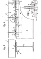
- Fig. 1 teilweise einen Querschnitt durch ein Mälzereigebäude mit einer Horde in Draufsicht, wobei der Hordenboden teilweise ausgebrochen dargestellt ist,
- Fig. 2 einen Querschnitt durch die Horde nach Linie II-II in Fig. 1,
- Fig. 3 einen Querschnitt durch einen Träger des Traggerüstes der Horde und die von ihm aufgenommene Klemmschiene sowie das von dieser gehaltene Blechhohlprofil im größeren Maßstab,
- Fig. 4 teilweise eine Seitenansicht des Traggerüstträgers nach Fig. 3 samt zugeordneter Klemmschiene und von letzterer fixierten Blechhohlprofilen, ebenfalls im größeren Maßstab und
- Fig. 5 einen vergrößert gezeichneten Ausschnitt aus Fig. 4 mit der Klemmschiene und einem ihrer Nasenpaare.
- Die beispielsweise zum Keimen von Grünmalz bestimmte, kreisförmige Horde besteht gemäß den Figuren 1 und 2 aus einem Traggerüst 1 und einem Boden 2. Das Traggerüst 1 ist aus horizontalen Trägern mit I-Profil und vertikalen Stützen 4 aufgebaut, welche die Träger 3 in annähernd gleichmäßigen Abständen unterstützen und auf dem Boden 5 des Gutbehandlungsraumes 6 stehen. Jeder der parallel verlaufenden Träger 3 ruht mit seinem einen Ende auf einem Lagerbock 7, der in einer Ausnehmung der Außenwand 8 des Mälzereigebäudes verankert ist, und mit seinem anderen Ende auf einem Lagerbock 9, welcher in einer Ausnehmung der Mittelsäule 10 oder in einer anderen Ausnehmung der Außenwand 8 fixiert ist.
- Der Boden 2 der Horde ist aus Blechhohlprofilen in Gestalt von im Querschnitt U-förmigen Klemmprofilen 11 zusammengesetzt. Die in endlichen Längen, zum Beispiel von 6 m Länge, als Halbzeug angelieferten Klemmprofile 11, welche beispielsweise aus Edelstahl oder Zinkblech gewalzt sein können, sind eng parallel aneinanderliegend als zu ihrer Längsachse queraxiale Reihen auf den Trägern 3 angeordnet, wobei sie wegen des kreisförmigen Querschnitts des Gutbehandlungsraumes 6 bzw. der Bogenform der Außenwand 8 des Mälzereigebäudes radial außen auf entsprechend kürzere Längen geschnitten sind (Fig. 1). Wie sich aus den Figuren 3 und 4 erkennen läßt, sind die Klemmprofile 11 als U-Profile ausgebildet, deren Stege 12 über die gesamte Länge der Klemmprofile 11 sich erstreckende Reihen Schlitze 15 für den Durchtritt der Keimluft haben und deren nach unten weisende Flansche 13,14 konvergieren und an ihren freien Enden je eine nach innen gerichtete Rastleiste 16 bzw. 17 besitzen.
- Zum Verbinden der Klemmprofile 11 untereinander dienen quer zu ihren Längsachsen auf jedem Träger 3 aufgelegte, stirnseitig aneinandergrenzende Klemmschienen 18 vorgegebener Länge, zum Beispiel von 1,50 m Länge (Fig. 4), die als rechtwinkelige Winkelprofile aus Blech geformt sind und einen horizontalen Schenkel 19 sowie einen vertikalen Schenkel 20 haben (Fig. 3), welcher die Klemmschiene 18 in horizontaler Ebene versteift. Mit ihrem Schenkel 19 liegen die Klemmschienen 18 auf dem zugeordneten Träger 3 auf und weisen am freien Ende dieses Schenkels'19 Nasenpaare 24 aus Nasen 21,22 auf, welche nach oben gerichtet sind; die Nasenpaare 24 sind mit einer Teilung 23 über die Länge der Klemmschiene 18 verteilt angeordnet, wobei die Teilung 23 gleich der Breite eines Klemmprofils 11 ist (Fig. 4). Die Nasen 21,22 jedes Nasenpaares 24 haben auf ihren einander zugekehrten Seiten je eine Rastkerbe 25 bzw. 26 (siehe den in Fig. 5 vergrößert dargestellten Ausschnitt, der in Fig. 4 durch einen Kreis markiert ist). In die Rastkerben 25,26 sind durch die Klemmwirkung der Flansche 14,13 sowie durch Druckausübung von oben bei der Montage auf das Klemmprofil 11 je eine Rastleiste 17 bzw. 16 eingerastet, und zwar ist jeweils - wie die Fig. 4 und 5 zeigen - die Rastleiste 16 des einen Flansches 13 eines Klemmprofiles 11 in die Rastkerbe 26 einer Nase 22 eines Nasenpaares 24 und die Rastleiste 1? seines anderen Flansches 14 in eine Rastkerbe 25 der Nase 21 des benachbarten Nasenpaares 24 eingerastet. Sollen die Klemmprofile 11 nicht nur untereinander, sondern auch mit den Trägern 3 des Traggerüstes verbunden werden, so kann dies in einfacher Weise dadurch geschehen, daß in Abständen Dellen 27 in die vertikalen Schenkel 20 der Klemmschienen 18 geschlagen werden, wodurch sie und die von ihnen gehaltenen bzw. durch sie verbundenen Klemmprofile 11 formschlüssig an den Trägern 3 und damit am Traggerüst 1 fixiert werden. Die Fig. 3 und 4 veranschaulichen beispielsweise eine solche Fixierung mittels Dellen 27.
Claims (5)
dadurch gekennzeichnet,
daß der Boden (2) aus parallel eng nebeneinander angeordneten, selbsttragenden Blechhohlprofilen (11) besteht, die mit Durchtrittsöffnungen (15) für das Gutbehandlungsmedium versehen und durch Verbindungsmittel (18) zusammengehalten sind.
dadurch gekennzeichnet,
daß die Blechhohlprofile als nach unten offene Klemmprofile (11) gestaltet sind.
dadurch gekennzeichnet,
daß die Klemmprofile (11) U-Profile sind, deren Flansche (13,14) nach unten weisen und konvergieren und an ihren freien Enden eine nach innen gerichtete Rastleiste (16,17) haben.
dadurch gekennzeichnet,
daß als Verbindungsmittel für die Blechhohlprofile (11) Klemmschienen (18) vorgesehen sind, welche auf das Traggerüst (1,3) verlegt sind.
dadurch gekennzeichnet,
daß die Klemmschienen (18) rechtwinkelige Winkelprofile aus Blech sind, die mit einem Schenkel (19) auf dem Traggerüst (1,3) liegen und am freien Ende dieses Schenkels (19) nach oben weisende Nasenpaare (24) aufweisen, welche mit einer Teilung (23) gleich der Breite der Klemmprofile (11) über die Länge der Klemmschiene (18) verteilt sind, wobei die beiden Nasen (21,22) jedes Nasenpaares (24) auf ihren einander zugekehrten Seiten je eine Rastkerbe (25 bzw. 26) zum Aufnehmen einer Rastleiste (17 bzw. 16) eines Klemmprofils (11) besitzen.
Applications Claiming Priority (2)
| Application Number | Priority Date | Filing Date | Title |
|---|---|---|---|
| DE3232977 | 1982-09-04 | ||
| DE3232977A DE3232977C1 (de) | 1982-09-04 | 1982-09-04 | Horde fuer Maelzereien und andere Gutbehandlungsraeume |
Publications (3)
| Publication Number | Publication Date |
|---|---|
| EP0104367A2 true EP0104367A2 (de) | 1984-04-04 |
| EP0104367A3 EP0104367A3 (en) | 1986-07-09 |
| EP0104367B1 EP0104367B1 (de) | 1988-12-28 |
Family
ID=6172513
Family Applications (1)
| Application Number | Title | Priority Date | Filing Date |
|---|---|---|---|
| EP83107587A Expired EP0104367B1 (de) | 1982-09-04 | 1983-08-02 | Horde für Mälzereien und andere Gutbehandlungsräume |
Country Status (5)
| Country | Link |
|---|---|
| US (2) | US4545137A (de) |
| EP (1) | EP0104367B1 (de) |
| DE (2) | DE3232977C1 (de) |
| ES (1) | ES274100Y (de) |
| FI (1) | FI76882C (de) |
Cited By (1)
| Publication number | Priority date | Publication date | Assignee | Title |
|---|---|---|---|---|
| FR2946361A1 (fr) * | 2009-06-04 | 2010-12-10 | Malteurope Groupe | Dispositif de plateau de malterie, touraille, germoir et outil de trempage |
Families Citing this family (7)
| Publication number | Priority date | Publication date | Assignee | Title |
|---|---|---|---|---|
| DE3232977C1 (de) * | 1982-09-04 | 1984-03-22 | Bühler-Miag GmbH, 3300 Braunschweig | Horde fuer Maelzereien und andere Gutbehandlungsraeume |
| ES2149654B1 (es) * | 1997-04-04 | 2001-05-16 | Seeger Ind Sa | Mejoras introducidas en cubas de remojo para malterias. |
| US6255102B1 (en) * | 1999-02-12 | 2001-07-03 | Hallsten Corporation | Modular support for biofiltration |
| NL1025609C2 (nl) * | 2004-03-01 | 2005-09-05 | Buehler Gmbh | Inrichting voor het weken van gerst. |
| US20090064616A1 (en) * | 2007-09-07 | 2009-03-12 | Yuquin Shan | Floor system for a grain bin |
| FR2946360B1 (fr) * | 2009-06-04 | 2011-06-24 | Malteurope Groupe | Dispositif de touraillage de grain ameliore |
| USD1082992S1 (en) | 2022-02-16 | 2025-07-08 | Implus Footcare, Llc | Hurdle |
Family Cites Families (13)
| Publication number | Priority date | Publication date | Assignee | Title |
|---|---|---|---|---|
| US532545A (en) * | 1895-01-15 | Malting-floor | ||
| US285246A (en) * | 1883-09-18 | James l | ||
| US2792644A (en) * | 1954-12-01 | 1957-05-21 | Albert Schwill & Company | Malting apparatus |
| US3426445A (en) * | 1966-08-22 | 1969-02-11 | Vincent B Steffen | Base for steel storage bin |
| GB1208603A (en) * | 1967-05-30 | 1970-10-14 | Bedford Sheet Metal Company Lt | Improvements in or relating to apparatus and a method of passing air through particulate material such as grain |
| CS164040B1 (de) * | 1973-05-18 | 1975-11-07 | ||
| US4137682A (en) * | 1977-11-29 | 1979-02-06 | Grain Systems, Inc. | Floor system for grain bin |
| GB1582203A (en) * | 1978-05-09 | 1981-01-07 | Ventec Agricultural Ltd | Drying shed floor elements |
| US4262584A (en) * | 1979-08-08 | 1981-04-21 | Dunbar Roger H | Grain tower aeration structure |
| US4281489A (en) * | 1979-09-24 | 1981-08-04 | Continental Agri-Services, Inc. | Floor support for grain drying and storage bin |
| US4282694A (en) * | 1979-11-08 | 1981-08-11 | Nixdorff Krein Industries, Inc. | Grain bin floor support system |
| DE3147671A1 (de) * | 1981-12-02 | 1983-07-14 | J.F. Nold & Co, 6081 Stockstadt | Verfahren zur herstellung von metall-horden |
| DE3232977C1 (de) * | 1982-09-04 | 1984-03-22 | Bühler-Miag GmbH, 3300 Braunschweig | Horde fuer Maelzereien und andere Gutbehandlungsraeume |
-
1982
- 1982-09-04 DE DE3232977A patent/DE3232977C1/de not_active Expired
-
1983
- 1983-07-22 FI FI832677A patent/FI76882C/fi not_active IP Right Cessation
- 1983-08-02 EP EP83107587A patent/EP0104367B1/de not_active Expired
- 1983-08-02 DE DE8383107587T patent/DE3378768D1/de not_active Expired
- 1983-08-24 ES ES1983274100U patent/ES274100Y/es not_active Expired
- 1983-08-24 US US06/526,165 patent/US4545137A/en not_active Expired - Fee Related
-
1985
- 1985-03-18 US US06/713,577 patent/US4667420A/en not_active Expired - Fee Related
Cited By (2)
| Publication number | Priority date | Publication date | Assignee | Title |
|---|---|---|---|---|
| FR2946361A1 (fr) * | 2009-06-04 | 2010-12-10 | Malteurope Groupe | Dispositif de plateau de malterie, touraille, germoir et outil de trempage |
| EP2258823A3 (de) * | 2009-06-04 | 2012-03-21 | Malteurop Groupe | Plateauvorrichtung zum Mälzen, Darren und Keimen, sowie Weichvorrichtung |
Also Published As
| Publication number | Publication date |
|---|---|
| US4667420A (en) | 1987-05-26 |
| FI832677A0 (fi) | 1983-07-22 |
| EP0104367A3 (en) | 1986-07-09 |
| US4545137A (en) | 1985-10-08 |
| ES274100Y (es) | 1984-08-01 |
| DE3378768D1 (en) | 1989-02-02 |
| FI832677L (fi) | 1984-03-05 |
| FI76882C (fi) | 1988-12-12 |
| ES274100U (es) | 1984-01-16 |
| DE3232977C1 (de) | 1984-03-22 |
| FI76882B (fi) | 1988-08-31 |
| EP0104367B1 (de) | 1988-12-28 |
Similar Documents
| Publication | Publication Date | Title |
|---|---|---|
| DE1559282C3 (de) | Raumkasten zur Montage eines Fertighauses | |
| DE69302390T2 (de) | Rahmen für ein gebäude | |
| DE2429916A1 (de) | Vorrichtung an schalldaemmenden waenden | |
| DE3232977C1 (de) | Horde fuer Maelzereien und andere Gutbehandlungsraeume | |
| EP0164330B1 (de) | Stahlbetondecke | |
| DE10196810T5 (de) | Verbundkonstruktionsteil, insbesondere zur Herstellung von Verkleidungs- und Wandkonstruktionen von Gebäuden | |
| DE102011079372A1 (de) | Tragende Konstruktion eines Gebäudes, welche Normalien und Sparren aufweist, Sparren und Verfahren zum Herstellen eines Sparrens | |
| DE2708400C2 (de) | Gebäude | |
| EP0299226A2 (de) | Schalung zum Herstellen von Betonbauteilen | |
| DE9214426U1 (de) | Stahlträger für eine Blechverbunddecke | |
| DE2702459A1 (de) | Verfahren zur befestigung von platten aus zerbrechlichem material an balken, saeulen o.dgl. laenglichen teilen und beschlaege zur durchfuehrung des verfahrens | |
| DE2157116A1 (de) | Dach- oder Wandkonstruktion | |
| DE2033550A1 (de) | Profilierter Trager zur Abstutzung und Verspannung von Platten | |
| DE2117499A1 (de) | Regalanlage | |
| EP3070225B1 (de) | Durchstanzbewehrungselement und bauwerk mit einer platte mit einem durchstanzbewehrungselement | |
| AT402419B (de) | Gitterträger | |
| DE2410118A1 (de) | Metallische struktur fuer das bauwesen | |
| DE1409788A1 (de) | Bewehrungsanordnung fuer aus Stahlbeton bestehende Gleistragplatten | |
| DE9311437U1 (de) | Bausatz fuer fachwerkbauten | |
| DE68911536T2 (de) | Stahlständer und vorgefertigtes Bauelement. | |
| DE2040668C3 (de) | Baustahlmatte | |
| DE2035372A1 (de) | Verfahren und Schalform zum Ein schalen von Bau bzw Tragwerksteilen aus Beton oder Stahlbeton | |
| DE2501758A1 (de) | Metalltraeger | |
| DE10204898A1 (de) | Neuartiges Trägersystem für Gebäude | |
| DE202022101458U1 (de) | Hybridmast |
Legal Events
| Date | Code | Title | Description |
|---|---|---|---|
| PUAI | Public reference made under article 153(3) epc to a published international application that has entered the european phase |
Free format text: ORIGINAL CODE: 0009012 |
|
| AK | Designated contracting states |
Designated state(s): BE DE FR GB NL |
|
| PUAL | Search report despatched |
Free format text: ORIGINAL CODE: 0009013 |
|
| AK | Designated contracting states |
Kind code of ref document: A3 Designated state(s): BE DE FR GB NL |
|
| 17P | Request for examination filed |
Effective date: 19861222 |
|
| 17Q | First examination report despatched |
Effective date: 19871223 |
|
| GRAA | (expected) grant |
Free format text: ORIGINAL CODE: 0009210 |
|
| AK | Designated contracting states |
Kind code of ref document: B1 Designated state(s): BE DE FR GB NL |
|
| GBT | Gb: translation of ep patent filed (gb section 77(6)(a)/1977) | ||
| REF | Corresponds to: |
Ref document number: 3378768 Country of ref document: DE Date of ref document: 19890202 |
|
| ET | Fr: translation filed | ||
| PLBE | No opposition filed within time limit |
Free format text: ORIGINAL CODE: 0009261 |
|
| STAA | Information on the status of an ep patent application or granted ep patent |
Free format text: STATUS: NO OPPOSITION FILED WITHIN TIME LIMIT |
|
| 26N | No opposition filed | ||
| PGFP | Annual fee paid to national office [announced via postgrant information from national office to epo] |
Ref country code: GB Payment date: 19960715 Year of fee payment: 14 |
|
| PGFP | Annual fee paid to national office [announced via postgrant information from national office to epo] |
Ref country code: FR Payment date: 19960716 Year of fee payment: 14 Ref country code: BE Payment date: 19960716 Year of fee payment: 14 |
|
| PGFP | Annual fee paid to national office [announced via postgrant information from national office to epo] |
Ref country code: DE Payment date: 19960722 Year of fee payment: 14 |
|
| PGFP | Annual fee paid to national office [announced via postgrant information from national office to epo] |
Ref country code: NL Payment date: 19960723 Year of fee payment: 14 |
|
| PG25 | Lapsed in a contracting state [announced via postgrant information from national office to epo] |
Ref country code: GB Free format text: LAPSE BECAUSE OF NON-PAYMENT OF DUE FEES Effective date: 19970802 |
|
| PG25 | Lapsed in a contracting state [announced via postgrant information from national office to epo] |
Ref country code: BE Free format text: LAPSE BECAUSE OF NON-PAYMENT OF DUE FEES Effective date: 19970831 |
|
| BERE | Be: lapsed |
Owner name: BUHLER-MIAG G.M.B.H. Effective date: 19970831 |
|
| PG25 | Lapsed in a contracting state [announced via postgrant information from national office to epo] |
Ref country code: NL Free format text: LAPSE BECAUSE OF NON-PAYMENT OF DUE FEES Effective date: 19980301 |
|
| GBPC | Gb: european patent ceased through non-payment of renewal fee |
Effective date: 19970802 |
|
| PG25 | Lapsed in a contracting state [announced via postgrant information from national office to epo] |
Ref country code: FR Free format text: LAPSE BECAUSE OF NON-PAYMENT OF DUE FEES Effective date: 19980430 |
|
| PG25 | Lapsed in a contracting state [announced via postgrant information from national office to epo] |
Ref country code: DE Free format text: LAPSE BECAUSE OF NON-PAYMENT OF DUE FEES Effective date: 19980501 |
|
| NLV4 | Nl: lapsed or anulled due to non-payment of the annual fee |
Effective date: 19980301 |
|
| REG | Reference to a national code |
Ref country code: FR Ref legal event code: ST |