EP0086400A1 - Dispositif d'alimentation des boudins de matière plastique en fusion à une glissière d'enlèvement inclinée - Google Patents
Dispositif d'alimentation des boudins de matière plastique en fusion à une glissière d'enlèvement inclinée Download PDFInfo
- Publication number
- EP0086400A1 EP0086400A1 EP83100972A EP83100972A EP0086400A1 EP 0086400 A1 EP0086400 A1 EP 0086400A1 EP 83100972 A EP83100972 A EP 83100972A EP 83100972 A EP83100972 A EP 83100972A EP 0086400 A1 EP0086400 A1 EP 0086400A1
- Authority
- EP
- European Patent Office
- Prior art keywords
- strands
- section
- operating position
- separating element
- drainage channel
- Prior art date
- Legal status (The legal status is an assumption and is not a legal conclusion. Google has not performed a legal analysis and makes no representation as to the accuracy of the status listed.)
- Granted
Links
Images


Classifications
-
- B—PERFORMING OPERATIONS; TRANSPORTING
- B29—WORKING OF PLASTICS; WORKING OF SUBSTANCES IN A PLASTIC STATE IN GENERAL
- B29B—PREPARATION OR PRETREATMENT OF THE MATERIAL TO BE SHAPED; MAKING GRANULES OR PREFORMS; RECOVERY OF PLASTICS OR OTHER CONSTITUENTS OF WASTE MATERIAL CONTAINING PLASTICS
- B29B9/00—Making granules
- B29B9/02—Making granules by dividing preformed material
- B29B9/06—Making granules by dividing preformed material in the form of filamentary material, e.g. combined with extrusion
-
- B—PERFORMING OPERATIONS; TRANSPORTING
- B29—WORKING OF PLASTICS; WORKING OF SUBSTANCES IN A PLASTIC STATE IN GENERAL
- B29C—SHAPING OR JOINING OF PLASTICS; SHAPING OF MATERIAL IN A PLASTIC STATE, NOT OTHERWISE PROVIDED FOR; AFTER-TREATMENT OF THE SHAPED PRODUCTS, e.g. REPAIRING
- B29C48/00—Extrusion moulding, i.e. expressing the moulding material through a die or nozzle which imparts the desired form; Apparatus therefor
- B29C48/03—Extrusion moulding, i.e. expressing the moulding material through a die or nozzle which imparts the desired form; Apparatus therefor characterised by the shape of the extruded material at extrusion
- B29C48/05—Filamentary, e.g. strands
-
- B—PERFORMING OPERATIONS; TRANSPORTING
- B29—WORKING OF PLASTICS; WORKING OF SUBSTANCES IN A PLASTIC STATE IN GENERAL
- B29C—SHAPING OR JOINING OF PLASTICS; SHAPING OF MATERIAL IN A PLASTIC STATE, NOT OTHERWISE PROVIDED FOR; AFTER-TREATMENT OF THE SHAPED PRODUCTS, e.g. REPAIRING
- B29C48/00—Extrusion moulding, i.e. expressing the moulding material through a die or nozzle which imparts the desired form; Apparatus therefor
- B29C48/25—Component parts, details or accessories; Auxiliary operations
- B29C48/355—Conveyors for extruded articles
-
- B—PERFORMING OPERATIONS; TRANSPORTING
- B29—WORKING OF PLASTICS; WORKING OF SUBSTANCES IN A PLASTIC STATE IN GENERAL
- B29C—SHAPING OR JOINING OF PLASTICS; SHAPING OF MATERIAL IN A PLASTIC STATE, NOT OTHERWISE PROVIDED FOR; AFTER-TREATMENT OF THE SHAPED PRODUCTS, e.g. REPAIRING
- B29C48/00—Extrusion moulding, i.e. expressing the moulding material through a die or nozzle which imparts the desired form; Apparatus therefor
- B29C48/25—Component parts, details or accessories; Auxiliary operations
- B29C48/88—Thermal treatment of the stream of extruded material, e.g. cooling
- B29C48/911—Cooling
-
- B—PERFORMING OPERATIONS; TRANSPORTING
- B29—WORKING OF PLASTICS; WORKING OF SUBSTANCES IN A PLASTIC STATE IN GENERAL
- B29C—SHAPING OR JOINING OF PLASTICS; SHAPING OF MATERIAL IN A PLASTIC STATE, NOT OTHERWISE PROVIDED FOR; AFTER-TREATMENT OF THE SHAPED PRODUCTS, e.g. REPAIRING
- B29C48/00—Extrusion moulding, i.e. expressing the moulding material through a die or nozzle which imparts the desired form; Apparatus therefor
- B29C48/25—Component parts, details or accessories; Auxiliary operations
- B29C48/88—Thermal treatment of the stream of extruded material, e.g. cooling
- B29C48/919—Thermal treatment of the stream of extruded material, e.g. cooling using a bath, e.g. extruding into an open bath to coagulate or cool the material
Definitions
- the invention relates to a device for supplying molten plastic strands to an oblique drainage channel, which extends at its upper end to behind the fall line of the strands emerging from nozzles, in the operating position catches the strands and can be moved into a forward position in which it free passage of the strands next to her allowed, with a cooling water inlet is directed to the upper end of the gutter.
- Such a device is known from DE-PS 2 503 455.
- the gutter merges in the region of its upper end into a pivotable flap which is mounted on an axis which runs transversely to the gutter and is arranged at the upper end of the flap in such a way that when the flap is pivoted these two positions can be assumed, namely an operating position , in which the side of the flap facing away from the axis merges into the drainage channel in such a way that, with regard to the flow of the strands and the cooling water, there is a closed structure in which the flap is part of the drainage channel, the flap hanging up the strands emerging from the nozzles and supplies with the cooling water of the gutter, and an inoperative position in which the flap is pivoted away from the gutter such that the strands emerging from the nozzles fall between the flap and the gutter.
- the so-called advance position it is generally a matter of first draining off the material initially emerging from the nozzles before the processing of plastic strands, which are then fed to the granulator via the drainage channel, since this generally contains or contains dirt has not yet reached its final uniform composition. If the flap is now pivoted back into its operating position, it must go through the fall line of the strands, which can get caught on the flap. In order to avoid this problem, one can either switch off the melt flow or interrupt the melt flow by painting over the relevant nozzle plate with a spatula or the like, which must be carried out by an operator, for the period of the pivoting of the flap from the forward position into the operating position .
- the invention has for its object to automate this process described above and to design such that movement when the flap moves from the forward position into the operating position, no fresh strands can get stuck on it.
- the drainage channel has at its upper end a section which can be displaced relative to it along a slide guide from the forward position to the operating position, which catches the strands in the operating position and to which a separating element is assigned, which is displaced when the end face of the section is moved the fall line of the strands in the forward position captures the strands and then cuts them.
- the section that can be moved from the forward position into the operating position ensures that the strands can be derived in the forward position, thereby preventing the strand material in question from reaching the granulate to be produced.
- the section in its operating position ensures that the strands made of full material are fed to the drainage channel, the strands being gripped by the separating element as the section moves from the forward position into the operating position, so that these can be kept away from the section. that they don’t stick to it.
- the after this capture the strands are then severed to ensure that the fresh strands can be discharged freely through the section and the gutter.
- the section itself can be provided with the separating element, with which the effectiveness of the separating element is directly coupled to the movement of the section.
- the separating element On the other hand, it is also possible to mount the separating element on its own guide and to couple it to the section via a controller, so that the necessary synchronization of the movement of the section and the separating element is brought about by the controller. Such a coupling is particularly useful if such a device already exists for the control of other processes in the device in question.
- a scraper knife can advantageously be used as the separating element, so that when the section moves into the operating position, it sweeps over a plate containing the nozzles and thereby interrupts the emerging strands. In the period of the interruption, the end face of the section then moves through the fall line of the strands, so that they cannot stick to this end face. The fresh strand material emerging after the interruption then reaches the section in the operating position, is collected by it and is fed to the drainage channel.
- a rod which is arranged at a distance above the upper end of the section and which on the movement of the section into the operating position opens the strands without significantly cooling them catches and holds on to the flowing strands until they tear off.
- the strands initially hang on the rod moving through the strands, but then fall off the rod due to gravity, since the spatially separated arrangement of the rod from the upper end of the section ensures that the rod is not cooled and consequently the strands on the rod initially maintain the molten state. In this state, the strands can then easily fall off the bar.
- DE-AS 2 230 187 it is known from DE-AS 2 230 187 to provide a slide in a device for pulling plastic strands out of extrusion nozzles and supplying the plastic strands into an upwardly open cooling bath container, which slide in its effective position, i.e. in their operating position, the strands from the cooling bath container and deflected so that they get into a collecting device.
- a knife is coupled to this slide, which can be extended and retracted into the fall line of the strands, which cuts off the plastic strands when the slide is moved out of its effective position.
- the invention proceeds in a fundamentally different way, since the section used in connection with the invention, which forms part of the drainage channel, in its effective position, namely its operating position, feeds the strands of the drainage channel, but in its non-operating position, the so-called forward position, the strands can freely fall by itself in order to keep them from the processing in this way.
- a component of the gutter which in this sense does not exist in the subject of DE-AS 2 230 187, is used for this, the first not yet perfect strand material to allow an essentially free passage without cooling, so that this strand material can accumulate as a waste cake that can be easily removed in this form.
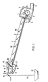
- the device shown in FIG. 1 contains the drainage channel 1, the structure of which can be found in more detail in DE-AS 2 503 455 mentioned above.
- Drainage channel 1 contains the bottom 2, over which the plastic strands slide down and at the end of the drainage channel 1 into the granulator 3 shown in principle.
- This contains the two feed rollers 4 and 5 and the cutter 6, which cooperates with the counter knife 7 in a known manner.
- the granulator 3 is additionally supplied with cooling water via the connection 8.
- the granulate produced in the granulator 3 is then discharged with the cooling water via the outlet 9.
- Spray nozzles 10 which are supplied with cooling water are arranged above the base 2 and provide an additional supply of cooling water along the drainage channel 1.
- the displaceable section 11 is provided, which is arranged to be movable back and forth in the horizontal direction in accordance with the double arrow shown.
- the displaceable section 11 forms the upper end of the drainage channel 1 and is therefore part of this.
- the displaceable section 11 further contains the water box 12, to which cooling water is supplied via the inlet 13, which exits through the slot 14, formed by the displaceable section 11 and the wall of the water box 12, runs away via the section 11 and then to the floor 2 of the gutter 1 arrives.
- the direction of the slot 14 and the pressure with which the cooling water is supplied to the water tank 12 ensures that the cooling water always flows from the slot 14 towards the drainage channel 1 at a considerable speed.
- the lever arm 16 is mounted on the water box 12 via the support 15 and is rotatably mounted on the axis 17 in its center. At its end facing away from the gutter 1, the lever 16 is provided with the scraper knife 18 which bears against the nozzle plate 19. The doctor blade 18 is pressed against the nozzle plate 19 by the tension spring 20 suspended in the lever 16.
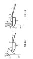
- section 11 In the operating position shown in FIG. 1, section 11 is in the forward position, in which strands 21 made of unprocessable material fall out of the nozzle plate 19 and reach the waste container 22. To the. Transition to the operating position, section 11 is shifted from the position shown in FIG. 1 to the left. This process is explained in more detail below with reference to FIGS. 2a and 2b.
- FIG. 2a shows a detail from FIG. 1, namely the displaceable section 11 in its forward position, in which an unprocessable strand 21 falls freely from the nozzle 23 in the nozzle plate 19.
- the scraper knife 18 is in a waiting position in front of the nozzle plate 19.
- a feed mechanism (not shown) that is not important in this connection, for example a pneumatically operated piston-cylinder unit
- the displaceable section 11 moves to the left the operating position shown in Figure 2b shifted, because of the mechanical connection of the stripping knife 18 and displaceable section 11, the stripping knife 18 is taken along and slides along the nozzle plate 19 in the position shown in Figure 2b, in the operating position of the section 11 from the nozzle plate 19 emerging strands.
- the exiting strands are separated and interrupted directly on the nozzle plate 19, so that the strand material following the interruption falls in the dash-dotted line 25 on the section 11 and is detected there by the stream of cooling water emerging from the slot 14.
- the cooling water then transports the fallen strands over section 11 towards the bottom 2 of the drainage channel, so that the strands run down over the bottom 2 together with the cooling water until the strands finally reach from in FIG were pelletizer 3 detected, which exerts a train on the strands in a known manner.
- the strands then assume the position designated by reference numeral 26 in FIG. 2b.
- the knife 18 is held in this operating position by the sleeve 40 indicated as a dash-dotted line.
- the operator switches automatically from the advance position shown in FIG. 2a to the operating position shown in FIG. 2b without manipulation of the operator and without interrupting the melt flow, the melt being fed to the waste in the form of melt strands 21 in the first operating phase and in the operating position shown in Figure 2b reaches the bottom 2 of the gutter.
- no melt initially intended for waste can be fed to the drainage channel, so that after the transition to the operating position shown in FIG. 2b, it receives only qualitatively perfect material.
- the rod 27, which runs transversely to the strands 21, is used as the separating element while parallel to the row of nozzles in the nozzle plate 19.
- the rod 27 is arranged at a distance from the end face 24 moved through the strands 21 above the slot 14, so that it cannot be cooled by the cooling water supplied to the water tank 12.
- FIGS. 4a and 4b show the part of the device according to FIG. 3 containing section 11 in the water tank 12 in the two operating phases, namely the forward position according to FIG. 4a and the operating position according to FIG. 4b.
- strands 21 consisting of unprocessable material initially flow down from the nozzles 23 into a waste container not shown in FIGS. 4a and 4b (see reference number 22 in FIG. 3).
- the operating phase shown in FIG. 4 corresponds entirely to that according to FIG. 2a. If the device is now brought into the operating position, the water box 12 with the section 11 is moved away from the bottom 2 of the drainage channel to the left into the operating position shown in FIG. 4b, the end face 24 running through the fall line 25 and strand material from the Rod 27 is caught.
- the end 29 is then thinned more and more by the flowing strand 26, which forms a loop in the direction of the bottom 2, until the end 29 is finally torn off the rod 27.
- the strand 26 then continues to flow over the section 11 towards the bottom 2 (see FIG. 4b) until finally the strand 26 is gripped by the granulator 3 (see FIG. 3) and assumes the stretched position shown in FIG. 4b.
- the rod 27 ensures that the strands are grasped by the rod 27 acting as a separating element and then severed during this transition from the forward position (FIG. 4a) to the operating position (FIG. 4b), which automatically switches the strand line from the supply to the waste to the supply to the gutter 1 results.
- the synchronization of the movement of the separating element, that is to say according to the illustrated exemplary embodiments of the doctor blade 18 or, the rod 27, with the movement of the displaceable section 11 can also be brought about by coupling these movements to one another via a control.
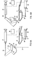
- a corresponding exemplary embodiment based on a separating knife as a separating element is shown in FIGS. 6a and 6b.
- FIG. 6a the device is shown in the forward position, in which the strands 21 fall freely from the nozzles 23.
- the pneumatically operated piston-cylinder unit 30 is provided, which engages with its plunger 31 on an arm 39 fastened to the water box 12. Due to the actuation of the piston-cylinder unit 30, the water box 12 with the section 11 is moved into the operating position shown in FIG. 6b, which corresponds to the explanations for FIGS. 2a and 2b.
- the stripping knife 32 is provided as a separating element in the device shown in FIGS. 6a and 6b, which is guided by means of the lever 34 mounted on the axis 33 over the nozzle plate 35 provided in this case with a cylindrical surface.
- the lever 34 with its end facing away from the stripping knife 32, is articulated on the piston rod 36 of the pneumatically actuated piston-cylinder unit 37, upon actuation of which the lever 34 executes a pivoting movement which finally transfers it to the operating position shown in FIG. 6b.
- control 38 which is only shown in principle, in such a way that a movement sequence results, as described with reference to FIGS. 2a and 2b.
- the controller 38 instead of the synchronization provided by mechanical connection of section 1 and doctor blade 18, there is a synchronization effected by the controller 38.
- Such controls are known, they are e.g. B. used in packaging machines, machine tools and the like. As sequence controls. Such a control can be used in particular in connection with the invention described here if the underlying device already contains a special control for other work processes.
- the device shown in FIG. 6 can also be used to remove oxidized melt deposits directly at the nozzle outlet, as such oxidations occur over a longer operating time. Such material is unusable for further processing. If it falls off the nozzle plate by itself, it is swept along by the water flow flowing over the displaceable section 11 and then usually causes contamination of the granulated material, in particular its discoloration. In order to avoid this, the device according to FIG. 6 can be moved back and forth during operation, that is to say from the operating position (FIG. 6b) to the forward position (FIG. 6a) and back again to the operating position, the nozzle plate 35 from the doctor blade 32 is swept. The doctor blade 32 takes the material oxidations mentioned with it.
- the control 38 is set in this case so that the movement of the doctor blade 32 from the operating position (FIG. 6b) to the forward position (FIG. 6a) Section 11 is shifted beforehand, so that section 11 is first brought from the operating position shown in FIG. 6b to the forward position shown in FIG. 6a, whereupon the doctor blade 32 then moves from the position according to FIG. 6b into the position according to FIG. 6a is transferred. Falling oxidations then fall into the waste. The movement of the doctor blade 32 and section 11 from the forward position (FIG. 6a) into the operating position (FIG. 6b) then takes place in a normal manner.
Applications Claiming Priority (2)
| Application Number | Priority Date | Filing Date | Title |
|---|---|---|---|
| DE3205052A DE3205052C2 (de) | 1982-02-12 | 1982-02-12 | Vorrichtung zum Zuleiten von aus Düsen schmelzflüssig austretenden Kunststoffsträngen zu einer Granuliervorrichtung |
| DE3205052 | 1982-02-12 |
Publications (2)
| Publication Number | Publication Date |
|---|---|
| EP0086400A1 true EP0086400A1 (fr) | 1983-08-24 |
| EP0086400B1 EP0086400B1 (fr) | 1986-12-30 |
Family
ID=6155562
Family Applications (1)
| Application Number | Title | Priority Date | Filing Date |
|---|---|---|---|
| EP83100972A Expired EP0086400B1 (fr) | 1982-02-12 | 1983-02-02 | Dispositif d'alimentation des boudins de matière plastique en fusion à une glissière d'enlèvement inclinée |
Country Status (3)
| Country | Link |
|---|---|
| EP (1) | EP0086400B1 (fr) |
| JP (1) | JPS58151208A (fr) |
| DE (2) | DE3205052C2 (fr) |
Cited By (9)
| Publication number | Priority date | Publication date | Assignee | Title |
|---|---|---|---|---|
| US5242289A (en) * | 1992-10-20 | 1993-09-07 | The Conair Group, Inc. | Apparatus for providing controlled cooling of thermoplastic strands |
| WO1993017850A1 (fr) * | 1992-03-12 | 1993-09-16 | Rieter Automatik Gmbh | Dispositif pour refroidir et granuler des joncs thermoplastiques sortant en fusion de filieres |
| EP0914929A1 (fr) * | 1997-11-06 | 1999-05-12 | Nokia - Maillefer Holding SA | Dispositif d'évacuation pour une purge d'une extrudeuse ou d'une tête d'extrusion |
| WO2000007797A1 (fr) * | 1998-08-03 | 2000-02-17 | Solvay (Societe Anonyme) | Dispositif pour purger une extrudeuse |
| EP0993927A1 (fr) * | 1998-10-15 | 2000-04-19 | C.F. SCHEER & CIE. GMBH & CO. | Dispositif de refroidissement pour des dispositifs de granulation de matières plastiques |
| WO2001019581A1 (fr) * | 1999-09-13 | 2001-03-22 | Rieter Automatik Gmbh | Dispositif d'acheminement de boudins de matiere synthetique en fusion sortant de filtres, jusqu'a un conduit de coulee |
| WO2013159931A1 (fr) * | 2012-04-26 | 2013-10-31 | Automatik Plastics Machinery Gmbh | Dispositif de coulée continue destiné à fabriquer des granulés à partir d'un matériau en fusion, et procédé permettant de le faire fonctionner |
| CN108656390A (zh) * | 2017-04-01 | 2018-10-16 | 常州塑金高分子科技有限公司 | 一种风冷切粒机 |
| CN115339779A (zh) * | 2022-08-12 | 2022-11-15 | 凯迈(洛阳)机电有限公司 | 一种可快速拆解的切粒机启动头水箱 |
Families Citing this family (12)
| Publication number | Priority date | Publication date | Assignee | Title |
|---|---|---|---|---|
| JPS6153118U (fr) * | 1984-09-13 | 1986-04-10 | ||
| JPS6190507U (fr) * | 1984-11-19 | 1986-06-12 | ||
| JPS61123504A (ja) * | 1984-11-20 | 1986-06-11 | Ishinaka Tekkosho:Kk | 溶融ストランドの冷却細断装置 |
| JPH0320085Y2 (fr) * | 1984-12-18 | 1991-04-30 | ||
| JPS61148006A (ja) * | 1984-12-21 | 1986-07-05 | Ishinaka Tekkosho:Kk | 溶融ストランドの冷却細断装置 |
| JPS62194015U (fr) * | 1986-05-31 | 1987-12-10 | ||
| DE3726606A1 (de) * | 1987-08-11 | 1989-03-02 | Guenter Hartig | Vorrichtung zum zufuehren und abkuehlen von straengen aus thermoplastischen kunststoffen |
| DE3900250A1 (de) * | 1989-01-05 | 1990-07-12 | Hench Automatik App Masch | Vorrichtung zum abkuehlen, trocknen und granulieren von straengen |
| DE4026371A1 (de) * | 1990-08-21 | 1992-02-27 | Daimler Benz Ag | Verfahren zur herstellung eines quarzglasrohlings |
| DE4117941C1 (fr) * | 1991-05-31 | 1992-05-07 | Automatik Apparate-Maschinenbau Gmbh, 8754 Grossostheim, De | |
| DE19933476B4 (de) * | 1999-07-16 | 2006-09-28 | Rieter Automatik Gmbh | Verfahren und Vorrichtung zur Zuleitung und Behandlung von Kunststoffsträngen |
| DE10139324C2 (de) * | 2001-08-10 | 2003-12-11 | Scheer & Cie C F | Vorrichtung zum Abkühlen von Kunststoffsträngen |
Citations (2)
| Publication number | Priority date | Publication date | Assignee | Title |
|---|---|---|---|---|
| DE2230187B2 (de) * | 1972-06-21 | 1974-10-03 | C.F. Scheer & Cie., 7000 Stuttgart | Vorrichtung zum Abziehen mehrerer Kunststoffstränge aus Extrusionsdüsen |
| DE2503455B2 (de) * | 1975-01-28 | 1977-06-16 | Ausscheidung in: 25 59 541 Automatik Apparate-Maschinenbau H. Hench GmbH, 8754 Großostheim | Vorrichtung zum abkuehlen und granulieren von straengen aus thermoplastischen kunststoffen |
Family Cites Families (3)
| Publication number | Priority date | Publication date | Assignee | Title |
|---|---|---|---|---|
| JPS4729206U (fr) * | 1971-04-23 | 1972-12-02 | ||
| JPS6029940B2 (ja) * | 1977-08-29 | 1985-07-13 | 株式会社リコー | 積層型電子写真感光体及びその製造法 |
| DE3145613C2 (de) * | 1981-11-17 | 1984-06-07 | Automatik Apparate-Maschinenbau H. Hench Gmbh, 8754 Grossostheim | Vorrichtung zum Zuleiten von aus Düsen schmelzflüssig austretenden Kunststoffsträngen zu einer Granuliervorrichtung |
-
1982
- 1982-02-12 DE DE3205052A patent/DE3205052C2/de not_active Expired
-
1983
- 1983-02-02 EP EP83100972A patent/EP0086400B1/fr not_active Expired
- 1983-02-02 DE DE8383100972T patent/DE3368548D1/de not_active Expired
- 1983-02-10 JP JP58021973A patent/JPS58151208A/ja active Granted
Patent Citations (2)
| Publication number | Priority date | Publication date | Assignee | Title |
|---|---|---|---|---|
| DE2230187B2 (de) * | 1972-06-21 | 1974-10-03 | C.F. Scheer & Cie., 7000 Stuttgart | Vorrichtung zum Abziehen mehrerer Kunststoffstränge aus Extrusionsdüsen |
| DE2503455B2 (de) * | 1975-01-28 | 1977-06-16 | Ausscheidung in: 25 59 541 Automatik Apparate-Maschinenbau H. Hench GmbH, 8754 Großostheim | Vorrichtung zum abkuehlen und granulieren von straengen aus thermoplastischen kunststoffen |
Cited By (13)
| Publication number | Priority date | Publication date | Assignee | Title |
|---|---|---|---|---|
| WO1993017850A1 (fr) * | 1992-03-12 | 1993-09-16 | Rieter Automatik Gmbh | Dispositif pour refroidir et granuler des joncs thermoplastiques sortant en fusion de filieres |
| US5441394A (en) * | 1992-03-12 | 1995-08-15 | Rieter Automatik Gmbh | Device for cooling and granulating molten thermoplastic strands emerging from dies |
| US5242289A (en) * | 1992-10-20 | 1993-09-07 | The Conair Group, Inc. | Apparatus for providing controlled cooling of thermoplastic strands |
| EP0914929A1 (fr) * | 1997-11-06 | 1999-05-12 | Nokia - Maillefer Holding SA | Dispositif d'évacuation pour une purge d'une extrudeuse ou d'une tête d'extrusion |
| BE1012108A3 (fr) * | 1998-08-03 | 2000-05-02 | Solvay | Dispositif pour purger une extrudeuse. |
| WO2000007797A1 (fr) * | 1998-08-03 | 2000-02-17 | Solvay (Societe Anonyme) | Dispositif pour purger une extrudeuse |
| EP0993927A1 (fr) * | 1998-10-15 | 2000-04-19 | C.F. SCHEER & CIE. GMBH & CO. | Dispositif de refroidissement pour des dispositifs de granulation de matières plastiques |
| WO2001019581A1 (fr) * | 1999-09-13 | 2001-03-22 | Rieter Automatik Gmbh | Dispositif d'acheminement de boudins de matiere synthetique en fusion sortant de filtres, jusqu'a un conduit de coulee |
| US6379137B1 (en) | 1999-09-13 | 2002-04-30 | Rieter Automatic Gmbh | Device for feeding strands of molten synthetic material that are issued from nozzles to a discharge chute |
| WO2013159931A1 (fr) * | 2012-04-26 | 2013-10-31 | Automatik Plastics Machinery Gmbh | Dispositif de coulée continue destiné à fabriquer des granulés à partir d'un matériau en fusion, et procédé permettant de le faire fonctionner |
| CN108656390A (zh) * | 2017-04-01 | 2018-10-16 | 常州塑金高分子科技有限公司 | 一种风冷切粒机 |
| CN115339779A (zh) * | 2022-08-12 | 2022-11-15 | 凯迈(洛阳)机电有限公司 | 一种可快速拆解的切粒机启动头水箱 |
| CN115339779B (zh) * | 2022-08-12 | 2024-04-30 | 凯迈(洛阳)机电有限公司 | 一种可快速拆解的切粒机启动头水箱 |
Also Published As
| Publication number | Publication date |
|---|---|
| DE3205052C2 (de) | 1984-10-31 |
| DE3205052A1 (de) | 1983-08-25 |
| JPS58151208A (ja) | 1983-09-08 |
| JPH0510203B2 (fr) | 1993-02-09 |
| DE3368548D1 (en) | 1987-02-05 |
| EP0086400B1 (fr) | 1986-12-30 |
Similar Documents
| Publication | Publication Date | Title |
|---|---|---|
| EP0086400B1 (fr) | Dispositif d'alimentation des boudins de matière plastique en fusion à une glissière d'enlèvement inclinée | |
| DE3145613C2 (de) | Vorrichtung zum Zuleiten von aus Düsen schmelzflüssig austretenden Kunststoffsträngen zu einer Granuliervorrichtung | |
| DE102006017017A1 (de) | Direktanbindung von Wurstclip- und Wurstfördereinrichtung | |
| EP0584325B1 (fr) | Dispositif pour refroidir et granuler des joncs thermoplastiques sortant en fusion de filieres | |
| EP0805741B1 (fr) | Dispositif de refroidissement et de granulation de joncs en matiere plastique | |
| DE3028713C2 (de) | Vorrichtung zum Vereinzeln von Stäben | |
| DE3638110A1 (de) | Vorrichtung zum pneumatischen falschdrallspinnen | |
| DE2655840B2 (de) | Vorrichtung zum Abkühlen und Granulieren von Strängen aus thermoplastischen Kunststoffen | |
| DE1510356A1 (de) | Vorrichtung zum Austauschen voller Spinnkannen gegen leere an einer Fuellstation | |
| DE2230187C3 (de) | Vorrichtung zum Abziehen mehrerer Kunststoffstränge aus Extrusionsdüsen | |
| DE3127181C2 (fr) | ||
| DE2354634A1 (de) | Beschickungsbehaelter fuer textilkaemmmaschinen oder dergleichen | |
| DE3020042A1 (de) | Vorrichtung zur herstellung von hohlglasartikeln | |
| DE4124702A1 (de) | Vorrichtung zur ueberfuehrung eines faserflors in einen verdichter | |
| DE3432507A1 (de) | Verfahren und vorrichtung zum reinigen von gegenstaenden | |
| WO2001019581A1 (fr) | Dispositif d'acheminement de boudins de matiere synthetique en fusion sortant de filtres, jusqu'a un conduit de coulee | |
| DE60318208T2 (de) | Vorrichtung zum vorbereiten von materialbahnen wie auf thermoformanlagen erzeugten fangleisten | |
| DE3019054C2 (de) | An einer Kunststoff-Spritzgießmaschine angeordnete Entnahmevorrichtung zum vereinzelten Entnehmen und Abgeben von Spritzlingen aus einer geöffneten Spritzgießform | |
| DE228603C (fr) | ||
| DE2855033A1 (de) | Spritzgiessmaschine | |
| DE931574C (de) | Ausstossvorrichtung mit Wandersaugduese fuer Karden | |
| DE3510374C2 (de) | Vorrichtung zum Trennen der Bestandteile eines extrudierten Profilstreifens | |
| DE1510356C (de) | Kannenwechselvornchtung an Spinnerei Vorbereitungsmaschinen | |
| DE1295176B (de) | Vorrichtung zum Zufuehren und Einfaedeln von kontinuierlich aus einem Strangpresskopf ausgepressten Kunststoffstraengen in einen Granulator | |
| DE1934981C3 (de) | Verfahren und Vorrichtung zur Herstellung einer Glasfadenmatte |
Legal Events
| Date | Code | Title | Description |
|---|---|---|---|
| PUAI | Public reference made under article 153(3) epc to a published international application that has entered the european phase |
Free format text: ORIGINAL CODE: 0009012 |
|
| PUAI | Public reference made under article 153(3) epc to a published international application that has entered the european phase |
Free format text: ORIGINAL CODE: 0009012 |
|
| AK | Designated contracting states |
Designated state(s): BE CH DE FR GB IT LI LU NL |
|
| 17P | Request for examination filed |
Effective date: 19831214 |
|
| RAP1 | Party data changed (applicant data changed or rights of an application transferred) |
Owner name: AUTOMATIK APPARATE-MASCHINENBAU GMBH |
|
| ITF | It: translation for a ep patent filed |
Owner name: DR. ING. A. RACHELI & C. |
|
| GRAA | (expected) grant |
Free format text: ORIGINAL CODE: 0009210 |
|
| AK | Designated contracting states |
Kind code of ref document: B1 Designated state(s): BE CH DE FR GB IT LI LU NL |
|
| REF | Corresponds to: |
Ref document number: 3368548 Country of ref document: DE Date of ref document: 19870205 |
|
| ET | Fr: translation filed | ||
| PLBI | Opposition filed |
Free format text: ORIGINAL CODE: 0009260 |
|
| 26 | Opposition filed |
Opponent name: C.F. SCHEER & CIE GMBH + CO. Effective date: 19870926 |
|
| NLR1 | Nl: opposition has been filed with the epo |
Opponent name: C.F. SCHEER & CIE GMBH |
|
| ITTA | It: last paid annual fee | ||
| PLBN | Opposition rejected |
Free format text: ORIGINAL CODE: 0009273 |
|
| STAA | Information on the status of an ep patent application or granted ep patent |
Free format text: STATUS: OPPOSITION REJECTED |
|
| 27O | Opposition rejected |
Effective date: 19921203 |
|
| NLR2 | Nl: decision of opposition | ||
| REG | Reference to a national code |
Ref country code: CH Ref legal event code: PFA Free format text: RIETER AUTOMATIK GMBH |
|
| ITPR | It: changes in ownership of a european patent |
Owner name: CAMBIO RAGIONE SOCIALE;RIETER AUTOMATIK GMBH |
|
| REG | Reference to a national code |
Ref country code: FR Ref legal event code: CD |
|
| NLT1 | Nl: modifications of names registered in virtue of documents presented to the patent office pursuant to art. 16 a, paragraph 1 |
Owner name: RIETER AUTOMATIK GESELLSCHAFT MIT BESCHRAENKTER HA |
|
| EPTA | Lu: last paid annual fee | ||
| PGFP | Annual fee paid to national office [announced via postgrant information from national office to epo] |
Ref country code: LU Payment date: 19950201 Year of fee payment: 13 |
|
| PG25 | Lapsed in a contracting state [announced via postgrant information from national office to epo] |
Ref country code: LU Free format text: LAPSE BECAUSE OF NON-PAYMENT OF DUE FEES Effective date: 19960202 |
|
| REG | Reference to a national code |
Ref country code: GB Ref legal event code: IF02 |
|
| PGFP | Annual fee paid to national office [announced via postgrant information from national office to epo] |
Ref country code: GB Payment date: 20020122 Year of fee payment: 20 |
|
| PGFP | Annual fee paid to national office [announced via postgrant information from national office to epo] |
Ref country code: NL Payment date: 20020214 Year of fee payment: 20 |
|
| PGFP | Annual fee paid to national office [announced via postgrant information from national office to epo] |
Ref country code: CH Payment date: 20020220 Year of fee payment: 20 |
|
| PGFP | Annual fee paid to national office [announced via postgrant information from national office to epo] |
Ref country code: FR Payment date: 20020221 Year of fee payment: 20 Ref country code: BE Payment date: 20020221 Year of fee payment: 20 |
|
| PGFP | Annual fee paid to national office [announced via postgrant information from national office to epo] |
Ref country code: DE Payment date: 20020326 Year of fee payment: 20 |
|
| PG25 | Lapsed in a contracting state [announced via postgrant information from national office to epo] |
Ref country code: LI Free format text: LAPSE BECAUSE OF EXPIRATION OF PROTECTION Effective date: 20030201 Ref country code: GB Free format text: LAPSE BECAUSE OF EXPIRATION OF PROTECTION Effective date: 20030201 Ref country code: CH Free format text: LAPSE BECAUSE OF EXPIRATION OF PROTECTION Effective date: 20030201 |
|
| PG25 | Lapsed in a contracting state [announced via postgrant information from national office to epo] |
Ref country code: NL Free format text: LAPSE BECAUSE OF EXPIRATION OF PROTECTION Effective date: 20030202 |
|
| REG | Reference to a national code |
Ref country code: GB Ref legal event code: PE20 Effective date: 20030201 |
|
| BE20 | Be: patent expired |
Owner name: *RIETER AUTOMATIK G.M.B.H. Effective date: 20030202 |
|
| REG | Reference to a national code |
Ref country code: CH Ref legal event code: PL |
|
| NLV7 | Nl: ceased due to reaching the maximum lifetime of a patent |
Effective date: 20030202 |
|
| APAH | Appeal reference modified |
Free format text: ORIGINAL CODE: EPIDOSCREFNO |