EP0086400A1 - Device for feeding molten plastic strands to a tilted gutter - Google Patents
Device for feeding molten plastic strands to a tilted gutter Download PDFInfo
- Publication number
- EP0086400A1 EP0086400A1 EP83100972A EP83100972A EP0086400A1 EP 0086400 A1 EP0086400 A1 EP 0086400A1 EP 83100972 A EP83100972 A EP 83100972A EP 83100972 A EP83100972 A EP 83100972A EP 0086400 A1 EP0086400 A1 EP 0086400A1
- Authority
- EP
- European Patent Office
- Prior art keywords
- strands
- section
- operating position
- separating element
- drainage channel
- Prior art date
- Legal status (The legal status is an assumption and is not a legal conclusion. Google has not performed a legal analysis and makes no representation as to the accuracy of the status listed.)
- Granted
Links
Images


Classifications
-
- B—PERFORMING OPERATIONS; TRANSPORTING
- B29—WORKING OF PLASTICS; WORKING OF SUBSTANCES IN A PLASTIC STATE IN GENERAL
- B29B—PREPARATION OR PRETREATMENT OF THE MATERIAL TO BE SHAPED; MAKING GRANULES OR PREFORMS; RECOVERY OF PLASTICS OR OTHER CONSTITUENTS OF WASTE MATERIAL CONTAINING PLASTICS
- B29B9/00—Making granules
- B29B9/02—Making granules by dividing preformed material
- B29B9/06—Making granules by dividing preformed material in the form of filamentary material, e.g. combined with extrusion
-
- B—PERFORMING OPERATIONS; TRANSPORTING
- B29—WORKING OF PLASTICS; WORKING OF SUBSTANCES IN A PLASTIC STATE IN GENERAL
- B29C—SHAPING OR JOINING OF PLASTICS; SHAPING OF MATERIAL IN A PLASTIC STATE, NOT OTHERWISE PROVIDED FOR; AFTER-TREATMENT OF THE SHAPED PRODUCTS, e.g. REPAIRING
- B29C48/00—Extrusion moulding, i.e. expressing the moulding material through a die or nozzle which imparts the desired form; Apparatus therefor
- B29C48/03—Extrusion moulding, i.e. expressing the moulding material through a die or nozzle which imparts the desired form; Apparatus therefor characterised by the shape of the extruded material at extrusion
- B29C48/05—Filamentary, e.g. strands
-
- B—PERFORMING OPERATIONS; TRANSPORTING
- B29—WORKING OF PLASTICS; WORKING OF SUBSTANCES IN A PLASTIC STATE IN GENERAL
- B29C—SHAPING OR JOINING OF PLASTICS; SHAPING OF MATERIAL IN A PLASTIC STATE, NOT OTHERWISE PROVIDED FOR; AFTER-TREATMENT OF THE SHAPED PRODUCTS, e.g. REPAIRING
- B29C48/00—Extrusion moulding, i.e. expressing the moulding material through a die or nozzle which imparts the desired form; Apparatus therefor
- B29C48/25—Component parts, details or accessories; Auxiliary operations
- B29C48/355—Conveyors for extruded articles
-
- B—PERFORMING OPERATIONS; TRANSPORTING
- B29—WORKING OF PLASTICS; WORKING OF SUBSTANCES IN A PLASTIC STATE IN GENERAL
- B29C—SHAPING OR JOINING OF PLASTICS; SHAPING OF MATERIAL IN A PLASTIC STATE, NOT OTHERWISE PROVIDED FOR; AFTER-TREATMENT OF THE SHAPED PRODUCTS, e.g. REPAIRING
- B29C48/00—Extrusion moulding, i.e. expressing the moulding material through a die or nozzle which imparts the desired form; Apparatus therefor
- B29C48/25—Component parts, details or accessories; Auxiliary operations
- B29C48/88—Thermal treatment of the stream of extruded material, e.g. cooling
- B29C48/911—Cooling
-
- B—PERFORMING OPERATIONS; TRANSPORTING
- B29—WORKING OF PLASTICS; WORKING OF SUBSTANCES IN A PLASTIC STATE IN GENERAL
- B29C—SHAPING OR JOINING OF PLASTICS; SHAPING OF MATERIAL IN A PLASTIC STATE, NOT OTHERWISE PROVIDED FOR; AFTER-TREATMENT OF THE SHAPED PRODUCTS, e.g. REPAIRING
- B29C48/00—Extrusion moulding, i.e. expressing the moulding material through a die or nozzle which imparts the desired form; Apparatus therefor
- B29C48/25—Component parts, details or accessories; Auxiliary operations
- B29C48/88—Thermal treatment of the stream of extruded material, e.g. cooling
- B29C48/919—Thermal treatment of the stream of extruded material, e.g. cooling using a bath, e.g. extruding into an open bath to coagulate or cool the material
Definitions
- the invention relates to a device for supplying molten plastic strands to an oblique drainage channel, which extends at its upper end to behind the fall line of the strands emerging from nozzles, in the operating position catches the strands and can be moved into a forward position in which it free passage of the strands next to her allowed, with a cooling water inlet is directed to the upper end of the gutter.
- Such a device is known from DE-PS 2 503 455.
- the gutter merges in the region of its upper end into a pivotable flap which is mounted on an axis which runs transversely to the gutter and is arranged at the upper end of the flap in such a way that when the flap is pivoted these two positions can be assumed, namely an operating position , in which the side of the flap facing away from the axis merges into the drainage channel in such a way that, with regard to the flow of the strands and the cooling water, there is a closed structure in which the flap is part of the drainage channel, the flap hanging up the strands emerging from the nozzles and supplies with the cooling water of the gutter, and an inoperative position in which the flap is pivoted away from the gutter such that the strands emerging from the nozzles fall between the flap and the gutter.
- the so-called advance position it is generally a matter of first draining off the material initially emerging from the nozzles before the processing of plastic strands, which are then fed to the granulator via the drainage channel, since this generally contains or contains dirt has not yet reached its final uniform composition. If the flap is now pivoted back into its operating position, it must go through the fall line of the strands, which can get caught on the flap. In order to avoid this problem, one can either switch off the melt flow or interrupt the melt flow by painting over the relevant nozzle plate with a spatula or the like, which must be carried out by an operator, for the period of the pivoting of the flap from the forward position into the operating position .
- the invention has for its object to automate this process described above and to design such that movement when the flap moves from the forward position into the operating position, no fresh strands can get stuck on it.
- the drainage channel has at its upper end a section which can be displaced relative to it along a slide guide from the forward position to the operating position, which catches the strands in the operating position and to which a separating element is assigned, which is displaced when the end face of the section is moved the fall line of the strands in the forward position captures the strands and then cuts them.
- the section that can be moved from the forward position into the operating position ensures that the strands can be derived in the forward position, thereby preventing the strand material in question from reaching the granulate to be produced.
- the section in its operating position ensures that the strands made of full material are fed to the drainage channel, the strands being gripped by the separating element as the section moves from the forward position into the operating position, so that these can be kept away from the section. that they don’t stick to it.
- the after this capture the strands are then severed to ensure that the fresh strands can be discharged freely through the section and the gutter.
- the section itself can be provided with the separating element, with which the effectiveness of the separating element is directly coupled to the movement of the section.
- the separating element On the other hand, it is also possible to mount the separating element on its own guide and to couple it to the section via a controller, so that the necessary synchronization of the movement of the section and the separating element is brought about by the controller. Such a coupling is particularly useful if such a device already exists for the control of other processes in the device in question.
- a scraper knife can advantageously be used as the separating element, so that when the section moves into the operating position, it sweeps over a plate containing the nozzles and thereby interrupts the emerging strands. In the period of the interruption, the end face of the section then moves through the fall line of the strands, so that they cannot stick to this end face. The fresh strand material emerging after the interruption then reaches the section in the operating position, is collected by it and is fed to the drainage channel.
- a rod which is arranged at a distance above the upper end of the section and which on the movement of the section into the operating position opens the strands without significantly cooling them catches and holds on to the flowing strands until they tear off.
- the strands initially hang on the rod moving through the strands, but then fall off the rod due to gravity, since the spatially separated arrangement of the rod from the upper end of the section ensures that the rod is not cooled and consequently the strands on the rod initially maintain the molten state. In this state, the strands can then easily fall off the bar.
- DE-AS 2 230 187 it is known from DE-AS 2 230 187 to provide a slide in a device for pulling plastic strands out of extrusion nozzles and supplying the plastic strands into an upwardly open cooling bath container, which slide in its effective position, i.e. in their operating position, the strands from the cooling bath container and deflected so that they get into a collecting device.
- a knife is coupled to this slide, which can be extended and retracted into the fall line of the strands, which cuts off the plastic strands when the slide is moved out of its effective position.
- the invention proceeds in a fundamentally different way, since the section used in connection with the invention, which forms part of the drainage channel, in its effective position, namely its operating position, feeds the strands of the drainage channel, but in its non-operating position, the so-called forward position, the strands can freely fall by itself in order to keep them from the processing in this way.
- a component of the gutter which in this sense does not exist in the subject of DE-AS 2 230 187, is used for this, the first not yet perfect strand material to allow an essentially free passage without cooling, so that this strand material can accumulate as a waste cake that can be easily removed in this form.
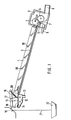
- the device shown in FIG. 1 contains the drainage channel 1, the structure of which can be found in more detail in DE-AS 2 503 455 mentioned above.
- Drainage channel 1 contains the bottom 2, over which the plastic strands slide down and at the end of the drainage channel 1 into the granulator 3 shown in principle.
- This contains the two feed rollers 4 and 5 and the cutter 6, which cooperates with the counter knife 7 in a known manner.
- the granulator 3 is additionally supplied with cooling water via the connection 8.
- the granulate produced in the granulator 3 is then discharged with the cooling water via the outlet 9.
- Spray nozzles 10 which are supplied with cooling water are arranged above the base 2 and provide an additional supply of cooling water along the drainage channel 1.
- the displaceable section 11 is provided, which is arranged to be movable back and forth in the horizontal direction in accordance with the double arrow shown.
- the displaceable section 11 forms the upper end of the drainage channel 1 and is therefore part of this.
- the displaceable section 11 further contains the water box 12, to which cooling water is supplied via the inlet 13, which exits through the slot 14, formed by the displaceable section 11 and the wall of the water box 12, runs away via the section 11 and then to the floor 2 of the gutter 1 arrives.
- the direction of the slot 14 and the pressure with which the cooling water is supplied to the water tank 12 ensures that the cooling water always flows from the slot 14 towards the drainage channel 1 at a considerable speed.
- the lever arm 16 is mounted on the water box 12 via the support 15 and is rotatably mounted on the axis 17 in its center. At its end facing away from the gutter 1, the lever 16 is provided with the scraper knife 18 which bears against the nozzle plate 19. The doctor blade 18 is pressed against the nozzle plate 19 by the tension spring 20 suspended in the lever 16.
- section 11 In the operating position shown in FIG. 1, section 11 is in the forward position, in which strands 21 made of unprocessable material fall out of the nozzle plate 19 and reach the waste container 22. To the. Transition to the operating position, section 11 is shifted from the position shown in FIG. 1 to the left. This process is explained in more detail below with reference to FIGS. 2a and 2b.
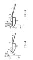
- FIG. 2a shows a detail from FIG. 1, namely the displaceable section 11 in its forward position, in which an unprocessable strand 21 falls freely from the nozzle 23 in the nozzle plate 19.
- the scraper knife 18 is in a waiting position in front of the nozzle plate 19.
- a feed mechanism (not shown) that is not important in this connection, for example a pneumatically operated piston-cylinder unit
- the displaceable section 11 moves to the left the operating position shown in Figure 2b shifted, because of the mechanical connection of the stripping knife 18 and displaceable section 11, the stripping knife 18 is taken along and slides along the nozzle plate 19 in the position shown in Figure 2b, in the operating position of the section 11 from the nozzle plate 19 emerging strands.
- the exiting strands are separated and interrupted directly on the nozzle plate 19, so that the strand material following the interruption falls in the dash-dotted line 25 on the section 11 and is detected there by the stream of cooling water emerging from the slot 14.
- the cooling water then transports the fallen strands over section 11 towards the bottom 2 of the drainage channel, so that the strands run down over the bottom 2 together with the cooling water until the strands finally reach from in FIG were pelletizer 3 detected, which exerts a train on the strands in a known manner.
- the strands then assume the position designated by reference numeral 26 in FIG. 2b.
- the knife 18 is held in this operating position by the sleeve 40 indicated as a dash-dotted line.
- the operator switches automatically from the advance position shown in FIG. 2a to the operating position shown in FIG. 2b without manipulation of the operator and without interrupting the melt flow, the melt being fed to the waste in the form of melt strands 21 in the first operating phase and in the operating position shown in Figure 2b reaches the bottom 2 of the gutter.
- no melt initially intended for waste can be fed to the drainage channel, so that after the transition to the operating position shown in FIG. 2b, it receives only qualitatively perfect material.
- the rod 27, which runs transversely to the strands 21, is used as the separating element while parallel to the row of nozzles in the nozzle plate 19.
- the rod 27 is arranged at a distance from the end face 24 moved through the strands 21 above the slot 14, so that it cannot be cooled by the cooling water supplied to the water tank 12.
- FIGS. 4a and 4b show the part of the device according to FIG. 3 containing section 11 in the water tank 12 in the two operating phases, namely the forward position according to FIG. 4a and the operating position according to FIG. 4b.
- strands 21 consisting of unprocessable material initially flow down from the nozzles 23 into a waste container not shown in FIGS. 4a and 4b (see reference number 22 in FIG. 3).
- the operating phase shown in FIG. 4 corresponds entirely to that according to FIG. 2a. If the device is now brought into the operating position, the water box 12 with the section 11 is moved away from the bottom 2 of the drainage channel to the left into the operating position shown in FIG. 4b, the end face 24 running through the fall line 25 and strand material from the Rod 27 is caught.
- the end 29 is then thinned more and more by the flowing strand 26, which forms a loop in the direction of the bottom 2, until the end 29 is finally torn off the rod 27.
- the strand 26 then continues to flow over the section 11 towards the bottom 2 (see FIG. 4b) until finally the strand 26 is gripped by the granulator 3 (see FIG. 3) and assumes the stretched position shown in FIG. 4b.
- the rod 27 ensures that the strands are grasped by the rod 27 acting as a separating element and then severed during this transition from the forward position (FIG. 4a) to the operating position (FIG. 4b), which automatically switches the strand line from the supply to the waste to the supply to the gutter 1 results.
- the synchronization of the movement of the separating element, that is to say according to the illustrated exemplary embodiments of the doctor blade 18 or, the rod 27, with the movement of the displaceable section 11 can also be brought about by coupling these movements to one another via a control.
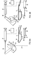
- a corresponding exemplary embodiment based on a separating knife as a separating element is shown in FIGS. 6a and 6b.
- FIG. 6a the device is shown in the forward position, in which the strands 21 fall freely from the nozzles 23.
- the pneumatically operated piston-cylinder unit 30 is provided, which engages with its plunger 31 on an arm 39 fastened to the water box 12. Due to the actuation of the piston-cylinder unit 30, the water box 12 with the section 11 is moved into the operating position shown in FIG. 6b, which corresponds to the explanations for FIGS. 2a and 2b.
- the stripping knife 32 is provided as a separating element in the device shown in FIGS. 6a and 6b, which is guided by means of the lever 34 mounted on the axis 33 over the nozzle plate 35 provided in this case with a cylindrical surface.
- the lever 34 with its end facing away from the stripping knife 32, is articulated on the piston rod 36 of the pneumatically actuated piston-cylinder unit 37, upon actuation of which the lever 34 executes a pivoting movement which finally transfers it to the operating position shown in FIG. 6b.
- control 38 which is only shown in principle, in such a way that a movement sequence results, as described with reference to FIGS. 2a and 2b.
- the controller 38 instead of the synchronization provided by mechanical connection of section 1 and doctor blade 18, there is a synchronization effected by the controller 38.
- Such controls are known, they are e.g. B. used in packaging machines, machine tools and the like. As sequence controls. Such a control can be used in particular in connection with the invention described here if the underlying device already contains a special control for other work processes.
- the device shown in FIG. 6 can also be used to remove oxidized melt deposits directly at the nozzle outlet, as such oxidations occur over a longer operating time. Such material is unusable for further processing. If it falls off the nozzle plate by itself, it is swept along by the water flow flowing over the displaceable section 11 and then usually causes contamination of the granulated material, in particular its discoloration. In order to avoid this, the device according to FIG. 6 can be moved back and forth during operation, that is to say from the operating position (FIG. 6b) to the forward position (FIG. 6a) and back again to the operating position, the nozzle plate 35 from the doctor blade 32 is swept. The doctor blade 32 takes the material oxidations mentioned with it.
- the control 38 is set in this case so that the movement of the doctor blade 32 from the operating position (FIG. 6b) to the forward position (FIG. 6a) Section 11 is shifted beforehand, so that section 11 is first brought from the operating position shown in FIG. 6b to the forward position shown in FIG. 6a, whereupon the doctor blade 32 then moves from the position according to FIG. 6b into the position according to FIG. 6a is transferred. Falling oxidations then fall into the waste. The movement of the doctor blade 32 and section 11 from the forward position (FIG. 6a) into the operating position (FIG. 6b) then takes place in a normal manner.
Abstract
Description
Die Erfindung bezieht sich auf eine Vorrichtung zum Zuleiten von schmelzflüssigen Kunststoffsträngen zu einer schrägen Ablaufrinne, die an ihrem oberen Ende bis hinter die Fallinie der aus Düsen austretenden Stränge reicht, in der Betriebslage die Stränge auffängt und in eine Vorlaufstellung bewegbar ist, in der sie den freien Durchtritt der Stränge neben ihr gestattet, wobei auf das obere Ende der Ablaufrinne ein Kühlwasserzulauf gerichtet ist.The invention relates to a device for supplying molten plastic strands to an oblique drainage channel, which extends at its upper end to behind the fall line of the strands emerging from nozzles, in the operating position catches the strands and can be moved into a forward position in which it free passage of the strands next to her allowed, with a cooling water inlet is directed to the upper end of the gutter.
Eine derartige Vorrichtung ist aus der DE-PS 2 503 455 bekannt. Bei dieser Vorrichtung geht die Ablaufrinne im Bereich ihres oberen Endes in eine verschwenkbare Klappe über, die auf einer quer zur Ablaufrinne verlaufenden, am oberen Ende der Klappe angeordneten Achse derart gelagert ist, daß beim Verschwenken der Klappe diese zwei Lagen einnehmen kann, nämlich eine Betriebslage, in der die der Achse abgewandte Seite der Klappe in die Ablaufrinne so übergeht, daß sich hinsichtlich des Ablaufs der Stränge und des Kühlwassers ein geschlossenes Gebilde ergibt, in dem die Klappe Bestandteil der Ablaufrinne ist, wobei die Klappe die aus den Düsen austretenden Stränge aufhängt und mit dem Kühlwasser der Ablaufrinne zuleitet, und eine Außerbetriebslage, in der die Klappe derart von der Ablaufrinne weggeschwenkt ist, daß die aus den Düsen austretenden Stränge zwischen der Klappe und der Ablaufrinne herabfallen.Such a device is known from DE-PS 2 503 455. In this device, the gutter merges in the region of its upper end into a pivotable flap which is mounted on an axis which runs transversely to the gutter and is arranged at the upper end of the flap in such a way that when the flap is pivoted these two positions can be assumed, namely an operating position , in which the side of the flap facing away from the axis merges into the drainage channel in such a way that, with regard to the flow of the strands and the cooling water, there is a closed structure in which the flap is part of the drainage channel, the flap hanging up the strands emerging from the nozzles and supplies with the cooling water of the gutter, and an inoperative position in which the flap is pivoted away from the gutter such that the strands emerging from the nozzles fall between the flap and the gutter.
Bei diesem Betriebszustand, der sogenannten Vorlaufstellung, handelt es sich im allgemeinen darum, vor Beginn der Verarbeitung von Kunststoffsträngen, die danach über die Ablaufrinne einem Granulator zugeführt werden, das anfangs aus den Düsen austretende Material zunächst abzuleiten, da dieses in der Regel Verschmutzungen enthält bzw. noch nicht seine endgültige gleichmäßige Zusammensetzung erfahren hat. Wird nun die Klappe in ihre Betriebslage zurückgeschwenkt, so muß sie die Fallinie der Stränge durchlaufen, die dabei an der Klappe hängenbleiben können. Um diesem Problem aus dem Wege zu gehen, kann man für den Zeitraum des Verschwenkens der Klappe aus der Vorlaufstellung in die Betriebslage entweder den Schmelzefluß abschalten oder den Schmelzefluß durch Überstreichen der betreffenden Düsenplatte mit einem Spachtel oder dergleichen unterbrechen, was durch eine Bedienungsperson durchgeführt werden muß.In this operating state, the so-called advance position, it is generally a matter of first draining off the material initially emerging from the nozzles before the processing of plastic strands, which are then fed to the granulator via the drainage channel, since this generally contains or contains dirt has not yet reached its final uniform composition. If the flap is now pivoted back into its operating position, it must go through the fall line of the strands, which can get caught on the flap. In order to avoid this problem, one can either switch off the melt flow or interrupt the melt flow by painting over the relevant nozzle plate with a spatula or the like, which must be carried out by an operator, for the period of the pivoting of the flap from the forward position into the operating position .
Der Erfindung liegt die Aufgabe zugrunde, diesen vorstehend beschriebenen Vorgang zu automatisieren und so zu gestalten, Bewegung daß bei der Bewegung der Klappe aus der Vorlaufstellung in die Betriebslage keine frischen Stränge an ihr hängenbleiben können.The invention has for its object to automate this process described above and to design such that movement when the flap moves from the forward position into the operating position, no fresh strands can get stuck on it.
Erfindungsgemäß geschieht dies dadurch, daß die Ablaufrinne an ihrem oberen Ende einen ihr gegenüber längs einer Schlittenführung aus der Vorlaufstellung in die Betriebslage verschiebbaren Abschnitt aufweist, der in der Betriebslage die Stränge auffängt und dem ein Trennelement zugeordnet ist, das beim Verschieben der Stirnseite des Abschnitts durch die Falllinie der Stränge in die Vorlauflage die Stränge erfaßt und anschließend durchtrennt.According to the invention, this is done in that the drainage channel has at its upper end a section which can be displaced relative to it along a slide guide from the forward position to the operating position, which catches the strands in the operating position and to which a separating element is assigned, which is displaced when the end face of the section is moved the fall line of the strands in the forward position captures the strands and then cuts them.
Durch den aus der Vorlaufstellung in die Betriebslage bewegbaren Abschnitt wird einerseits dafür gesorgt, daß die Stränge in der Vorlaufstellung abgeleitet werden können, wodurch vermieden wird, daß das betreffende Strangmaterial in das herzustellende Granulat gelangt. Andererseits sorgt der Abschnitt in seiner Betriebslage dafür, die aus vollwertigem Material bestehenden Stränge der Ablaufrinne zuzuleiten, wobei mit der Bewegung des Abschnitts aus der Vorlaufstellung in die Betriebslage durch das Trennelement die Stränge erfaßt werden, womit diese von dem Abschnitt so fern gehalten werden können, daß sie nicht an diesem ankleben. Die nach dieser Erfassung der Stränge erfolgende Durchtrennung der Stränge sorgt dann dafür, daß die frischen Stränge ungehindert über den Abschnitt und die Ablaufrinne abgeleitet werden können.The section that can be moved from the forward position into the operating position ensures that the strands can be derived in the forward position, thereby preventing the strand material in question from reaching the granulate to be produced. On the other hand, the section in its operating position ensures that the strands made of full material are fed to the drainage channel, the strands being gripped by the separating element as the section moves from the forward position into the operating position, so that these can be kept away from the section. that they don’t stick to it. The after this capture the strands are then severed to ensure that the fresh strands can be discharged freely through the section and the gutter.
Da das vorstehend beschriebene Wirksamwerden des Trennelementes beim Verschieben der Stirnseite des Abschnitts durch die Fallinie der Stränge erfolgt, kann man den Abschnitt selbst mit dem Trennelement versehen, womit das Wirksamwerden des Trennelementes mit der Bewegung des Abschnitts direkt gekoppelt ist.Since the above-described effectiveness of the separating element takes place when the end face of the section is displaced by the fall line of the strands, the section itself can be provided with the separating element, with which the effectiveness of the separating element is directly coupled to the movement of the section.
Andererseits ist es auch möglich, das Trennelement auf einer eigenen Führung anzubringen und diese über eine Steuerung mit dem Abschnitt zu koppeln, so daß die erforderliche Synchronisierung der Bewegung des Abschnitts und des Trennelementes durch die Steuerung herbeigeführt wird. Eine derartige Kopplung ist insbesondere dann sinnvoll, wenn eine solche bei der betreffenden Vorrichtung bereits für die Steuerung anderer Vorgänge existiert.On the other hand, it is also possible to mount the separating element on its own guide and to couple it to the section via a controller, so that the necessary synchronization of the movement of the section and the separating element is brought about by the controller. Such a coupling is particularly useful if such a device already exists for the control of other processes in the device in question.
Als Trennelement kann man vorteilhaft ein Abstreifmesser verwenden, daß bei der Bewegung des Abschnitts in die Betriebslage eine die Düsen enthaltende Platte überstreicht und dabei die austretenden Stränge unterbricht. Im Zeitraum der Unterbrechung bewegt sich dann die Stirnseite des Abschnitts durch die Fallinie der Stränge hindurch, so daß diese nicht an dieser Stirnseite festkleben können. Das nach der Unterbrechung austretende frische-Strangmaterial gelangt dann auf den in der Betriebslage befindlichen Abschnitt, wird von diesem aufgefangen und der Ablaufrinne zugeleitet.A scraper knife can advantageously be used as the separating element, so that when the section moves into the operating position, it sweeps over a plate containing the nozzles and thereby interrupts the emerging strands. In the period of the interruption, the end face of the section then moves through the fall line of the strands, so that they cannot stick to this end face. The fresh strand material emerging after the interruption then reaches the section in the operating position, is collected by it and is fed to the drainage channel.
Es ist aber auch möglich, als Trennelement eine mit Abstand oberhalb des oberen Endes des Abschnitts angeordnete Stange zu verwenden, die bei der Bewegung des Abschnitts in die Betriebslage die Stränge ohne deren wesentliche Abkühlung auffängt und gegenüber den weiterfließenden Strängen bis.zu deren Abreißen festhält. An der durch die Stränge hindurchbewegten Stange hängen sich die Stränge zunächst auf, fallen dann jedoch aufgrund der Schwerkraft von der Stange ab, da durch die räumlich getrennte Anordnung der Stange vom oberen Ende des Abschnitts dafür gesorgt ist, daß die Stange nicht gekühlt wird und infolgedessen die Stränge an der Stange zunächst den schmelzflüssigen Zustand beibehalten. In diesem Zustand der Stränge können diese dann ohne weiteres von der Stange abfallen.However, it is also possible to use as a separating element a rod which is arranged at a distance above the upper end of the section and which on the movement of the section into the operating position opens the strands without significantly cooling them catches and holds on to the flowing strands until they tear off. The strands initially hang on the rod moving through the strands, but then fall off the rod due to gravity, since the spatially separated arrangement of the rod from the upper end of the section ensures that the rod is not cooled and consequently the strands on the rod initially maintain the molten state. In this state, the strands can then easily fall off the bar.
Es sei noch darauf hingewiesen, daß es aus der DE-AS 2 230 187 bekannt ist, bei einer Vorrichtung zum Abziehen von Kunststoffsträngen aus Extrusionsdüsen und Zuleitung der Kunststoffstränge in einen nach oben offenen Kühlbadbehälter eine Rutsche vorzusehen, die in ihrer wirksamen Stellung, also in ihrer Betriebslage, die Stränge von dem Kühlbadbehälter ableitet und so umlenkt, daß sie in eine Auffangvorrichtung gelangen. Mit dieser in die Fallinie der Stränge ein- und ausfahrbaren Rutsche ist ein Messer gekoppelt, daß die Kunststoffstränge beim Herausfahren der Rutsche aus ihrer wirksamen Stellung abschneidet.It should also be pointed out that it is known from DE-AS 2 230 187 to provide a slide in a device for pulling plastic strands out of extrusion nozzles and supplying the plastic strands into an upwardly open cooling bath container, which slide in its effective position, i.e. in their operating position, the strands from the cooling bath container and deflected so that they get into a collecting device. A knife is coupled to this slide, which can be extended and retracted into the fall line of the strands, which cuts off the plastic strands when the slide is moved out of its effective position.
Die Erfindung geht demgegenüber einen grundsätzlich anderen Weg, da der im Zusammenhang mit der Erfindung verwendete, einen Bestandteil der Ablaufrinne bildende Abschnitt in seiner wirksamen Stellung, nämlich seiner Betriebslage, die Stränge der Ablaufrinne zuleitet, dagegen in seiner Außerbetriebslage, der sogenannten Vorlaufstellung, die Stränge frei an sich vorbeifallen läßt, um diese auf diese Weise von dem Verarbeitungsvorgang fernzuhalten. Bei der Erfindung wird also ein Bestandteil der Ablaufrinne, das es in diesem Sinne beim Gegenstand der DE-AS 2 230 187 nicht gibt, dazu ausgenutzt, dem zunächst noch nicht einwandfreien Strangmaterial einen im wesentlichen freien Durchtritt ohne Kühlung zu gestatten, so daß sich dieses Strangmaterial als Abfallkuchen ansammeln kann, der sich in dieser Form leicht abtransportieren läßt. Demgegenüber muß beim Gegenstand der DE-AS 2 230 187 die Rutsche gekühlt werden, da sie aktiv in ihrer Betriebsstellung dafür sorgt, die zunächst unverarbeitbaren Stränge abzuleiten. Ohne Kühlung der Rutsche würden diese an ihr festkleben. Mithin entsteht bei dieser Art der Ableitung unverarbeitbaren Strangmaterials ein Stranggewirr mit wesentlich niedrigerem Volumengewicht als der vorstehend erwähnte Abfallkuchen. Das Gewirr läßt sich wesentlich schlechter beseitigen läßt als ein Abfallkuchen.In contrast, the invention proceeds in a fundamentally different way, since the section used in connection with the invention, which forms part of the drainage channel, in its effective position, namely its operating position, feeds the strands of the drainage channel, but in its non-operating position, the so-called forward position, the strands can freely fall by itself in order to keep them from the processing in this way. In the invention, therefore, a component of the gutter, which in this sense does not exist in the subject of DE-AS 2 230 187, is used for this, the first not yet perfect strand material to allow an essentially free passage without cooling, so that this strand material can accumulate as a waste cake that can be easily removed in this form. In contrast, the slide in the subject of DE-AS 2 230 187 must be cooled since it actively ensures in its operating position that the initially unprocessable strands are derived. Without cooling the slide, they would stick to it. Thus, this type of derivation of unprocessable strand material creates a tangle of strands with a significantly lower volume weight than the waste cake mentioned above. The tangle is much more difficult to remove than a waste cake.
In den Figuren ist ein Ausführungsbeispiel der Erfindung dargestellt. Es zeigen
- Figur 1 die Vorrichtung mit einem am verschiebbaren Abschnitt angebrachten Abstreifmesser als Trennelement,
- Figuren 2a und 2b der den verschiebbaren Abschnitt und das Abstreifmesser enthaltene Teil der Figur 1 in vergrößerter Darstellung in zwei Betriebsphasen,
- Figur 3 die Vorrichtung mit einer am verschiebbaren Abschnitt angebrachten Stange als Trennelement,
- Figuren 4a und 4b der den verschiebbaren Abschnitt und die Stange enthaltende Teil der Figur 3 in vergrößerter Darstellung in zwei Betriebsphasen,
- Figur 5 eine vergrößerte Darstellung der Betriebsphase gemäß Figur 4b mit gerade aufgefangenem _ Strang,
- Figuren 6a und 6b der den verschiebbaren Abschnitt enthaltende Teil der Vorrichtung und ein Abstreifmesser, das über eine Steuerung mit dem verschiebbaren Abschnitt gekoppelt ist.
- 1 shows the device with a scraper blade attached to the displaceable section as a separating element,
- FIGS. 2a and 2b the part of FIG. 1 which contains the displaceable section and the doctor blade in an enlarged representation in two operating phases,
- 3 shows the device with a rod attached to the displaceable section as a separating element,
- 4a and 4b the part of FIG. 3 containing the displaceable section and the rod in an enlarged representation in two operating phases,
- FIG. 5 shows an enlarged representation of the operating phase according to FIG. 4b with the strand just caught,
- FIGS. 6a and 6b the part of the device which contains the displaceable section and a scraper knife which is coupled to the displaceable section via a controller.
Die in Figur 1 dargestellte Vorrichtung enthält die.Ablaufrinne 1, deren Aufbau in näher detaillierter Weise der oben erwähnten DE-AS 2 503 455 zu entnehmen ist. Ablaufrinne 1 enthält den Boden 2, über den die Kunststoffstränge hinabgleiten und am Ende der Ablaufrinne 1 in den prinzipiell dargestellten Granulator 3 gelangt. Dieser enthält die beiden Einzugswalzen 4 und 5 sowie den Fräser 6, der in bekannter Weise mit dem Gegenmesser 7 zusammenwirkt. Dem Granulator 3 wird zusätzlich Kühlwasser über den Anschluß 8 zugeführt. Das im Granulator 3 erzeugte Granulat wird dann mit dem Kühlwasser über den Auslaß 9 abgeleitet. Oberhalb des Bodens 2 sind mit Kühlwasser beschickte Sprühdüsen 10 angeordnet, die längs der Ablaufrinne 1 für eine zusätzliche Kühlwasserzufuhr sorgen. Am oberen Ende der Ablaufrinne 1 ist der verschiebbare Abschnitt 11 vorgesehen, der entsprechend dem eingezeichneten Doppelpfeil in horizontaler Richtung hin und her verschiebbar angeordnet ist. Der verschiebbare Abschnitt 11 bildet das obere Ende der Ablaufrinne 1 und ist somit Bestandteil von dieser. Der verschiebbare Abschnitt 11 enthält weiterhin den Wasserkasten 12, dem über den Zulauf 13 Kühlwasser zugeführt wird, das durch den Schlitz 14, gebildet durch den verschiebbaren Abschnitt 11 und die Wandung des Wasserkastens 12, austritt, über den Abschnitt 11 wegläuft und danach auf den Boden 2 der Ablaufrinne 1 gelangt. Durch die Richtung des Schlitzes 14 und den Druck, mit dem das Kühlwasser dem Wasserkasten 12 zugeleitet wird, wird dafür gesorgt, daß das Kühlwasser aus dem Schlitz 14 stets mit erheblicher Geschwindigkeit in Richtung auf die Ablaufrinne 1 zuströmt.The device shown in FIG. 1 contains the drainage channel 1, the structure of which can be found in more detail in DE-AS 2 503 455 mentioned above. Drainage channel 1 contains the
An dem Wasserkasten 12 ist über die Stütze 15 der Hebelarm 16 angebracht, der in seiner Mitte drehbar auf der Achse 17 gelagert ist. An seinem der Ablaufrinne 1 abgewandten Ende ist der Hebel 16 mit dem Abstreifmesser 18 versehen, das an der Düsenplatte 19 anliegt. Das Abstreifmesser 18 wird durch die in den Hebel 16 eingehängte Zugfeder 20 gegen die Düsenplatte 19 gedrückt.The
In der in der Figur 1 dargestellten Betriebslage befindet sich der Abschnitt 11 in der Vorlaufstellung, in der aus unverarbeitbarem Material bestehende Stränge 21 aus der Düsenplatte 19 herabfallen und in den Abfallbehälter 22 gelangen. Zum. Übergang in die Betriebslage wird der Abschnitt 11 aus der in Figur 1 dargestellten Lage nach links hin verschoben. Dieser Vorgang sei nachstehend anhand der Figuren 2a und 2b näher erläutert.In the operating position shown in FIG. 1,
Figur 2a zeigt einen Ausschnitt aus Figur 1, und zwar den verschiebbaren Abschnitt 11 in seiner Vorlaufstellung, in der ein unverarbeitbarer Strang 21 aus der Düse 23 in der Düsenplatte 19 frei herabfällt. In dieser Vorlaufstellung steht das Abstreifmesser 18 gewissermaßen in Wartestellung vor der Düsenplatte 19. Wird nun durch einen nicht dargestellten Vorschubmechanismus, auf den es in diesem Zusammenhang nicht ankommt, beispielsweise eine pneumatisch betätigte Kolben-Zylinder-Einheit, der verschiebbare Abschnitt 11 nach links hin in die in Figur 2b dargestellte Betriebslage verschoben, so wird wegen der mechanischen Verbindung von Abstreifmesser 18 und verschiebbarem Abschnitt 11 das Abstreifmesser 18 mitgenommen und gleitet entlang der Düsenplatte 19 in die in Figur 2b dargestellte Lage, in der als Betriebslage der Abschnitt 11 die aus der Düsenplatte 19 austretenden Stränge auffängt. Bei diesem Vorgang werden unmittelbar an der Düsenplatte 19 die austretenden Stränge abgetrennt und unterbrochen, so daß das der Unterbrechung folgende Strangmaterial in der strichpunktiert eingezeichneten Fallinie 25 auf den Abschnitt 11 herabfällt und dort vom Strom des aus dem Schlitz 14 austretenden Kühlwasser erfaßt wird. Das Kühlwasser transportiert dann die herabgefallenen Stränge über den Abschnitt 11 in Richtung auf den Boden 2 der Ablaufrinne, so daß die Stränge über den Boden 2 zusammen mit dem Kühlwasser hinablaufen, bis die Stränge schließlich vom in Figur 1 dargestellten Granulator 3 erfaßt werden, der in bekannter Weise einen Zug auf die Stränge ausübt. Die Stränge nehmen dann die in der Figur 2b mit dem Bezugszeichen 26 bezeichnete Lage ein. Das Messer 18 wird in dieser Betriebslage durch die als strichpunktierte Linie angedeutete Hülse 40 gehalten.FIG. 2a shows a detail from FIG. 1, namely the
Bei diesem Vorgang der Unterbrechung der aus der Düsenplatte 19 austretenden Stränge unter der Wirkung des Abstreifmessers 18 tritt die Stirnseite 24 des Wasserkastens 12 durch die Fallinie 25 der Stränge hindurch, wobei im Falle günstiger Einstellung der Unterbrechung die Stirnseite 24 mit keinem der herabfallenden Stränge in Berührung kommt. Sollte jedoch eine solche Berührung eintreten, so ist dies nicht problematisch, da an der vom Kühlwasser gekühlten Stirnseite 24 die Stränge nicht kleben bleiben können, so daß sie unmittelbar nach Erreichen der in der Figur 2b dargestellten Betriebslage von der Stirnseite 24 abfallen.In this process of interrupting the strands emerging from the
Bei diesem Vorgang wird also automatisch ohne eine Manipulation der Bedienungsperson und ohne Unterbrechung des Schmelzestromes von der in Figur 2a dargestellten Vorlaufstellung in die in Figur 2b gezeigte Betriebslage umgeschaltet, wobei in der ersteren Betriebsphase die Schmelze in Form der Schmelzestränge 21 dem Abfall zugeleitet wird und in der in Figur 2b dargestellten Betriebslage zum Boden 2 der Ablaufrinne gelangt. Dabei kann keine zunächst für den Abfall bestimmte Schmelze der Ablaufrinne zugeleitet werden, so daß diese nach Übergang in die in Figur 2b dargestellte Betriebslage nur qualitativ einwandfreies Material erhält.In this process, the operator switches automatically from the advance position shown in FIG. 2a to the operating position shown in FIG. 2b without manipulation of the operator and without interrupting the melt flow, the melt being fed to the waste in the form of
Bei der in Figur 3 dargestellten Vorrichtung, die hinsichtlich der Ablaufrinne 1, dem Granulator 3 und dem Wasserkasten 12 mit verschiebbarem Abschnitt 11 mit der Vorrichtung gemäß Figur 1 übereinstimmt, wird als Trennelement die Stange 27 verwendet, die quer zu den Strängen 21 verläuft, und zwar dabei parallel zur Reihe der Düsen in der Düsenplatte 19. Die Stange 27 ist mit Abstand von der durch die Stränge 21 hindurchbewegten Stirnseite 24 oberhalb des Schlitzes 14 angeordnet, so daß sie durch das dem Wasserkasten 12 zugeführte Kühlwasser nicht gekühlt werden kann.In the device shown in FIG. 3, which corresponds to the device according to FIG. 1 with regard to the drainage channel 1, the granulator 3 and the
Die Wirkungsweise der Stange 27 sei nunmehr anhand der Figuren 4a und 4b näher erläutert, die den im Wasserkasten 12 mit Abschnitt 11 enthaltenden Teil der Vorrichtung gemäß Figur 3 in den beiden Betriebsphasen, nämlich Vorlaufstellung gemäß Figur 4a und Betriebsstellung gemäß Figur 4b, zeigen.The mode of operation of the
Bei der in Figur 4a dargestellten Vorlaufstellung fließen zunächst aus unverarbeitbarem Material bestehende Stränge 21 aus den Düsen 23 herab in einen in den Figuren 4a und 4b nicht dargestellten Abfallbehälter (siehe Bezugszeichen 22 in Figur 3). Insofern entspricht die in Figur 4 dargestellte Betriebsphase völlig derjenigen gemäß Figur 2a. Wenn nun die Vorrichtung in die Betriebslage gebracht wird, so wird der Wasserkasten 12 mit dem Abschnitt 11 vom Boden 2 der Ablaufrinne weg nach links hin in die in Figur 4b dargestellte Betriebslage verschoben, wobei die Stirnseite 24 durch die Fallinie 25 hindurchläuft und Strangmaterial von der Stange 27 aufgefangen wird.In the forward position shown in FIG. 4a,
Anhand der Darstellung in Figur 5 sei nunmehr die Wirkung der Stange 27 näher erläutert. Beim Hindurchtreten der Stange 27 durch die Stränge 21 (siehe Figur 4a) hängen sich die Stränge an der Stange 27 auf, wobei sie im Bereich der Stange 27 ihre Temperatur behalten, da die Stange 27 nicht gekühlt ist. Infolgedessen dehnen sich die beiden beidseitig der Stange 27 herabhängenden Enden jedes Stranges, also einerseits das zum Abfall gerichtete Ende 28 und andererseits das zum verschiebbaren Abschnitt 11 gerichtete Ende 29 aus, bis durch diese Ausdehnung das Ende 28 schließlich von der Stange 27 zum Abfall herabfällt. An der Stirnseite 24 kann dabei dieses Ende 28 nicht festkleben, weil die Stirnseite 24 gekühlt ist.The effect of the
Das Ende 29 wird dann von dem nachfließenden Strang 26, der in Richtung zum Boden 2 eine Schlaufe bildet, mehr und mehr ausgedünnt, bis das Ende 29 schließlich von der Stange 27 abgerissen wird. Es fließt dann weiterhin der Strang 26 über den Abschnitt 11 in Richtung auf den Boden 2 (siehe Figur 4b), bis schließlich der Strang 26-vom Granulator 3 (siehe Figur 3) erfaßt wird und die in Figur 4b dargestellte, gestreckte Lage einnimmt.The
Wie ersichtlich, sorgt also bei diesem übergang von Vorlaufstellung (Figur 4a) in die Betriebslage (Figur 4b) die Stange 27 dafür, daß die Stränge von der als Trennelement wirkenden Stange 27 erfaßt und anschließend durchtrennt werden, wodurch sich automatisch eine Umschaltung der Strangleitung von der Zufuhr zum Abfall zur Zufuhr zur Ablaufrinne 1 ergibt.As can be seen, the
Die Synchronisierung der Bewegung des Trennelements, also gemäß den dargestellten Ausführungsbeispielen des Abstreifmessers 18 bzw., der Stange 27, mit der Bewegung des verschiebbaren Abschnitts 11 läßt sich auch dadurch herbeiführen, daß man diese Bewegungen über eine Steuerung miteinander koppelt. Ein entsprechendes Ausführungsbeispiel unter Zugrundelegung eines Trennmessers als Trennelement ist in den Figuren 6a und 6b dargestellt.The synchronization of the movement of the separating element, that is to say according to the illustrated exemplary embodiments of the
In Figur 6a ist die Vorrichtung in der Vorlaufstellung gezeigt, in der die Stränge 21 aus den Düsen 23 frei herabfallen. Für die Bewegung des Wasserkastens 12 ist hier die pneumatisch betätigte Kolben-Zylinder-Einheit 30 vorgesehen, die mit ihrem Stößel 31 an einem an den Wasserkasten 12 befestigten Arm 39 ansetzt. Aufgrund der Betätigung der Kolben-Zylinder-Einheit 30 wird der Wasserkasten 12 mit dem Abschnitt 11 in die in Figur 6b dargestellte Betriebslage verschoben, was den Erläuterungen zu den Figuren 2a und 2b entspricht.In Figure 6a, the device is shown in the forward position, in which the
Als Trennelement ist bei den in Figuren 6a und 6b därgestelten Vorrichtung das Abstreifmesser 32 vorgesehen, das mittels des auf der Achse 33 gelagerten Hebels 34 über die in diesem Falle mit einer zylindrischen Oberfläche versehene Düsenplatte 35 geführt wird. Der Hebel 34 ist mit seinem dem Abstreifmesser 32 abgewandten Ende an der Kolbenstange 36 der pneumatisch betätigten Kolben-Zylinder-Einheit 37 angelenkt, bei deren Betätigung der Hebel 34 eine Verschwenkbewegung ausführt, die ihn schließlich in die in Figur 6b dargestellte Betriebslage überführt.The stripping
Die Bewegung des verschiebbaren Abschnitts 11 und des Abstreifmessers 32 wird nun mittels der nur prinzipiell dargestellten Steuerung 38 so eingestellt, daß sich ein Bewegungsablauf ergibt, wie er anhand der Figuren 2a und 2b beschrieben ist. Anstelle der durch mechanische Verbindung von Abschnitt 1 und Abstreifmesser 18 gegebenen Synchronisierung liegt hier eine durch die Steuerung 38 bewirkte Synchronisierung vor. Derartige Steuerungen sind bekannt, sie werden z. B. bei Verpackungsmaschinen, Werkzeugmaschinen und dgl. als Ablaufsteuerungen verwendet. Eine derartige Steuerung kann insbesondere dann im Zusammenhang mit der hier beschriebenen Erfindung verwendet werden, wenn die zugrundeliegende Vorrichtung für andere Arbeitsabläufe bereits eine besondere Steuerung enthält.The movement of the
Aufgrund der Steuerung 38 wird also hinsichtlich des Bewegungsablaufs die gleiche Wirkung wie bei der Vorrichtung gemäß den Figuren 2a und 2b erzielt, so daß hinsichtlich der Wirkungsweise der Vorrichtung gemäß den Figuren 6a und 6b auf die Erläuterungen zu Figuren 2a und 2b verwiesen werden kann. Es sei noch darauf hingewiesen, daß im Zusammenhang mit einer besonderen Steuerung als Trennelement natürlich auch eine Stange, wie die Stange 27, verwendet werden kann, der in diesem Falle ähnlich dem Hebel 34 ein eigener Vorschubmechanismus zu geben ist.Due to the
Die in Figur 6 dargestellte Vorrichtung kann auch dazu verwendet werden, oxydierte Schmelzeablagerungen unmittelbar am Düsenaustritt zu entfernen, wie solche Oxydationen im Laufe einer längeren Betriebszeit entstehen. Derartiges Material ist für den weiteren Verarbeitungsprozeß unbrauchbar. Fällt es von selbst von der Düsenplatte ab, so wird es von dem über den verschiebbaren Abschnitt 11 fließenden Wasserstrom mitgeschwemmt und bewirkt dann meist eine Verschmutzung des granulierten Materials, insbesondere dessen Verfärbung. Um dies zu vermeiden, kann die Vorrichtung gemäß Fig. 6 während des Betriebes hin und her verschoben werden, also aus der Betriebslage (Fig. 6b) in die Vorlaufstellung (Fig. 6a) und wieder zurück in die Betriebslage, wobei die Düsenplatte 35 von dem Abstreifmesser 32 überstrichen wird. Dabei nimmt das Abstreifmesser 32 die erwähnten Materialoxydationen mit. Damit nun derartige Materialoxydationen vom Abstreifmesser 32 nicht auf den verschiebbaren Abschnitt 11 fallen können, wird in diesem Falle die Steuerung 38 so eingestellt, daß für die Bewegung des Abstreifmessers 32 aus der Betriebslage (Fig. 6b) in die Vorlaufstellung (Fig. 6a) der Abschnitt 11 schon vorher verschoben wird, so daß zunächst der Abschnitt 11 aus der in Fig. 6b dargestellten Betriebslage in die in Fig. 6a gezeigte Vorlaufstellung gebracht wird, woraufhin dann das Abstreifmesser 32 aus der Lage gemäß Fig. 6b in die Lage gemäß Fig. 6a überführt wird. Dabei herabfallende Oxydationen fallen dann also in den Abfall. Die Bewegung von Abstreifmesser 32 und Abschnitt 11 aus der Vorlaufstellung (Fig. 6a) in die Betriebslage (Fig. 6b) erfolgt dann in normaler Weise.The device shown in FIG. 6 can also be used to remove oxidized melt deposits directly at the nozzle outlet, as such oxidations occur over a longer operating time. Such material is unusable for further processing. If it falls off the nozzle plate by itself, it is swept along by the water flow flowing over the
Claims (5)
Applications Claiming Priority (2)
| Application Number | Priority Date | Filing Date | Title |
|---|---|---|---|
| DE3205052A DE3205052C2 (en) | 1982-02-12 | 1982-02-12 | Device for feeding molten plastic strands emerging from nozzles to a granulating device |
| DE3205052 | 1982-02-12 |
Publications (2)
| Publication Number | Publication Date |
|---|---|
| EP0086400A1 true EP0086400A1 (en) | 1983-08-24 |
| EP0086400B1 EP0086400B1 (en) | 1986-12-30 |
Family
ID=6155562
Family Applications (1)
| Application Number | Title | Priority Date | Filing Date |
|---|---|---|---|
| EP83100972A Expired EP0086400B1 (en) | 1982-02-12 | 1983-02-02 | Device for feeding molten plastic strands to a tilted gutter |
Country Status (3)
| Country | Link |
|---|---|
| EP (1) | EP0086400B1 (en) |
| JP (1) | JPS58151208A (en) |
| DE (2) | DE3205052C2 (en) |
Cited By (9)
| Publication number | Priority date | Publication date | Assignee | Title |
|---|---|---|---|---|
| US5242289A (en) * | 1992-10-20 | 1993-09-07 | The Conair Group, Inc. | Apparatus for providing controlled cooling of thermoplastic strands |
| WO1993017850A1 (en) * | 1992-03-12 | 1993-09-16 | Rieter Automatik Gmbh | Device for cooling and granulating molten thermoplastic strands emerging from dies |
| EP0914929A1 (en) * | 1997-11-06 | 1999-05-12 | Nokia - Maillefer Holding SA | Purge discharging device for extruder or extrusion nozzle |
| WO2000007797A1 (en) * | 1998-08-03 | 2000-02-17 | Solvay (Societe Anonyme) | Device for purging an extruder |
| EP0993927A1 (en) * | 1998-10-15 | 2000-04-19 | C.F. SCHEER & CIE. GMBH & CO. | Chilling apparatus for plastic granulators |
| WO2001019581A1 (en) * | 1999-09-13 | 2001-03-22 | Rieter Automatik Gmbh | Device for feeding strands of molten synthetic material that are issued from nozzles to a discharge chute |
| WO2013159931A1 (en) * | 2012-04-26 | 2013-10-31 | Automatik Plastics Machinery Gmbh | Continuous casting device for producing granules from melt material and method for the operation thereof |
| CN108656390A (en) * | 2017-04-01 | 2018-10-16 | 常州塑金高分子科技有限公司 | A kind of air-cooled pelleter |
| CN115339779A (en) * | 2022-08-12 | 2022-11-15 | 凯迈(洛阳)机电有限公司 | Granulator starting head water tank capable of being disassembled quickly |
Families Citing this family (12)
| Publication number | Priority date | Publication date | Assignee | Title |
|---|---|---|---|---|
| JPS6153118U (en) * | 1984-09-13 | 1986-04-10 | ||
| JPS6190507U (en) * | 1984-11-19 | 1986-06-12 | ||
| JPS61123504A (en) * | 1984-11-20 | 1986-06-11 | Ishinaka Tekkosho:Kk | Apparatus for cooling and chopping melted strand |
| JPH0320085Y2 (en) * | 1984-12-18 | 1991-04-30 | ||
| JPS61148006A (en) * | 1984-12-21 | 1986-07-05 | Ishinaka Tekkosho:Kk | Cooling and chopping device of molten strand |
| JPS62194015U (en) * | 1986-05-31 | 1987-12-10 | ||
| DE3726606A1 (en) * | 1987-08-11 | 1989-03-02 | Guenter Hartig | DEVICE FOR FEEDING AND COOLING STRINGS OF THERMOPLASTIC PLASTICS |
| DE3900250A1 (en) * | 1989-01-05 | 1990-07-12 | Hench Automatik App Masch | DEVICE FOR COOLING, DRYING AND GRANULATING STRINGS |
| DE4026371A1 (en) * | 1990-08-21 | 1992-02-27 | Daimler Benz Ag | Deposition of quartz glass layer for use in optical fibres - consists of burning silicon-contg. volatile cpds. in flame which is directed at the substrate surface |
| DE4117941C1 (en) * | 1991-05-31 | 1992-05-07 | Automatik Apparate-Maschinenbau Gmbh, 8754 Grossostheim, De | |
| DE19933476B4 (en) * | 1999-07-16 | 2006-09-28 | Rieter Automatik Gmbh | Method and device for the supply and treatment of plastic strands |
| DE10139324C2 (en) * | 2001-08-10 | 2003-12-11 | Scheer & Cie C F | Device for cooling plastic strands |
Citations (2)
| Publication number | Priority date | Publication date | Assignee | Title |
|---|---|---|---|---|
| DE2230187B2 (en) * | 1972-06-21 | 1974-10-03 | C.F. Scheer & Cie., 7000 Stuttgart | Device for pulling several plastic strands from extrusion nozzles |
| DE2503455B2 (en) * | 1975-01-28 | 1977-06-16 | Ausscheidung in: 25 59 541 Automatik Apparate-Maschinenbau H. Hench GmbH, 8754 Großostheim | DEVICE FOR COOLING AND GRANULATING STRIPS MADE OF THERMOPLASTIC PLASTICS |
Family Cites Families (3)
| Publication number | Priority date | Publication date | Assignee | Title |
|---|---|---|---|---|
| JPS4729206U (en) * | 1971-04-23 | 1972-12-02 | ||
| JPS6029940B2 (en) * | 1977-08-29 | 1985-07-13 | 株式会社リコー | Laminated electrophotographic photoreceptor and its manufacturing method |
| DE3145613C2 (en) * | 1981-11-17 | 1984-06-07 | Automatik Apparate-Maschinenbau H. Hench Gmbh, 8754 Grossostheim | Device for feeding molten plastic strands emerging from nozzles to a granulating device |
-
1982
- 1982-02-12 DE DE3205052A patent/DE3205052C2/en not_active Expired
-
1983
- 1983-02-02 DE DE8383100972T patent/DE3368548D1/en not_active Expired
- 1983-02-02 EP EP83100972A patent/EP0086400B1/en not_active Expired
- 1983-02-10 JP JP58021973A patent/JPS58151208A/en active Granted
Patent Citations (2)
| Publication number | Priority date | Publication date | Assignee | Title |
|---|---|---|---|---|
| DE2230187B2 (en) * | 1972-06-21 | 1974-10-03 | C.F. Scheer & Cie., 7000 Stuttgart | Device for pulling several plastic strands from extrusion nozzles |
| DE2503455B2 (en) * | 1975-01-28 | 1977-06-16 | Ausscheidung in: 25 59 541 Automatik Apparate-Maschinenbau H. Hench GmbH, 8754 Großostheim | DEVICE FOR COOLING AND GRANULATING STRIPS MADE OF THERMOPLASTIC PLASTICS |
Cited By (12)
| Publication number | Priority date | Publication date | Assignee | Title |
|---|---|---|---|---|
| WO1993017850A1 (en) * | 1992-03-12 | 1993-09-16 | Rieter Automatik Gmbh | Device for cooling and granulating molten thermoplastic strands emerging from dies |
| US5441394A (en) * | 1992-03-12 | 1995-08-15 | Rieter Automatik Gmbh | Device for cooling and granulating molten thermoplastic strands emerging from dies |
| US5242289A (en) * | 1992-10-20 | 1993-09-07 | The Conair Group, Inc. | Apparatus for providing controlled cooling of thermoplastic strands |
| EP0914929A1 (en) * | 1997-11-06 | 1999-05-12 | Nokia - Maillefer Holding SA | Purge discharging device for extruder or extrusion nozzle |
| WO2000007797A1 (en) * | 1998-08-03 | 2000-02-17 | Solvay (Societe Anonyme) | Device for purging an extruder |
| BE1012108A3 (en) * | 1998-08-03 | 2000-05-02 | Solvay | Purge device for an extruder. |
| EP0993927A1 (en) * | 1998-10-15 | 2000-04-19 | C.F. SCHEER & CIE. GMBH & CO. | Chilling apparatus for plastic granulators |
| WO2001019581A1 (en) * | 1999-09-13 | 2001-03-22 | Rieter Automatik Gmbh | Device for feeding strands of molten synthetic material that are issued from nozzles to a discharge chute |
| US6379137B1 (en) | 1999-09-13 | 2002-04-30 | Rieter Automatic Gmbh | Device for feeding strands of molten synthetic material that are issued from nozzles to a discharge chute |
| WO2013159931A1 (en) * | 2012-04-26 | 2013-10-31 | Automatik Plastics Machinery Gmbh | Continuous casting device for producing granules from melt material and method for the operation thereof |
| CN108656390A (en) * | 2017-04-01 | 2018-10-16 | 常州塑金高分子科技有限公司 | A kind of air-cooled pelleter |
| CN115339779A (en) * | 2022-08-12 | 2022-11-15 | 凯迈(洛阳)机电有限公司 | Granulator starting head water tank capable of being disassembled quickly |
Also Published As
| Publication number | Publication date |
|---|---|
| JPH0510203B2 (en) | 1993-02-09 |
| DE3205052A1 (en) | 1983-08-25 |
| DE3368548D1 (en) | 1987-02-05 |
| JPS58151208A (en) | 1983-09-08 |
| DE3205052C2 (en) | 1984-10-31 |
| EP0086400B1 (en) | 1986-12-30 |
Similar Documents
| Publication | Publication Date | Title |
|---|---|---|
| EP0086400B1 (en) | Device for feeding molten plastic strands to a tilted gutter | |
| DE3145613C2 (en) | Device for feeding molten plastic strands emerging from nozzles to a granulating device | |
| EP0584325B1 (en) | Device for cooling and granulating molten thermoplastic strands emerging from dies | |
| EP0805741B1 (en) | Device for cooling and granulating strands of plastic | |
| DE3028713C2 (en) | Device for separating bars | |
| DE3638110A1 (en) | DEVICE FOR PNEUMATIC SPIRAL SPINNING | |
| DE2655840B2 (en) | Device for cooling and granulating strands made of thermoplastics | |
| DE1510356A1 (en) | Device for exchanging full spinning cans for empty ones at a filling station | |
| DE2230187C3 (en) | Device for pulling several plastic strands from extrusion nozzles | |
| DE3127181C2 (en) | ||
| DE2354634A1 (en) | LOADING CONTAINER FOR TEXTILE EMBLEMING MACHINES OR THE LIKE | |
| DE3020042A1 (en) | DEVICE FOR PRODUCING HOLLOW GLASS ITEMS | |
| DE1109089B (en) | Sorting device with upwardly pivoting conveyor track sections | |
| DE4124702A1 (en) | Transfer appts. to carry web to condenser - has row of jets below gap between roller and guide plate with jet to roll web into silver | |
| DE3432507A1 (en) | Method and apparatus for cleaning articles | |
| WO2001019581A1 (en) | Device for feeding strands of molten synthetic material that are issued from nozzles to a discharge chute | |
| DE60318208T2 (en) | DEVICE FOR PREPARING MATERIAL TRACKS SUCH AS THERMOFORMING PLANTS | |
| DE3019054C2 (en) | Removal device arranged on a plastic injection molding machine for the isolated removal and dispensing of injection molded parts from an open injection mold | |
| DE228603C (en) | ||
| DE2855033A1 (en) | Automatic ejector for injection mould - in which pneumatic cylinder piston rod grips moulding swivels and releases on to chute | |
| DE931574C (en) | Ejection device with traveling suction nozzle for cards | |
| DE3510374C2 (en) | Device for separating the components of an extruded profile strip | |
| DE1510356C (en) | Can changing device on spinning preparation machines | |
| DE1934981C3 (en) | Method and device for producing a glass thread mat | |
| DE3526073A1 (en) | Process and device for cleaning a heated tool of a heated tool welding device |
Legal Events
| Date | Code | Title | Description |
|---|---|---|---|
| PUAI | Public reference made under article 153(3) epc to a published international application that has entered the european phase |
Free format text: ORIGINAL CODE: 0009012 |
|
| PUAI | Public reference made under article 153(3) epc to a published international application that has entered the european phase |
Free format text: ORIGINAL CODE: 0009012 |
|
| AK | Designated contracting states |
Designated state(s): BE CH DE FR GB IT LI LU NL |
|
| 17P | Request for examination filed |
Effective date: 19831214 |
|
| RAP1 | Party data changed (applicant data changed or rights of an application transferred) |
Owner name: AUTOMATIK APPARATE-MASCHINENBAU GMBH |
|
| ITF | It: translation for a ep patent filed |
Owner name: DR. ING. A. RACHELI & C. |
|
| GRAA | (expected) grant |
Free format text: ORIGINAL CODE: 0009210 |
|
| AK | Designated contracting states |
Kind code of ref document: B1 Designated state(s): BE CH DE FR GB IT LI LU NL |
|
| REF | Corresponds to: |
Ref document number: 3368548 Country of ref document: DE Date of ref document: 19870205 |
|
| ET | Fr: translation filed | ||
| PLBI | Opposition filed |
Free format text: ORIGINAL CODE: 0009260 |
|
| 26 | Opposition filed |
Opponent name: C.F. SCHEER & CIE GMBH + CO. Effective date: 19870926 |
|
| NLR1 | Nl: opposition has been filed with the epo |
Opponent name: C.F. SCHEER & CIE GMBH |
|
| ITTA | It: last paid annual fee | ||
| PLBN | Opposition rejected |
Free format text: ORIGINAL CODE: 0009273 |
|
| STAA | Information on the status of an ep patent application or granted ep patent |
Free format text: STATUS: OPPOSITION REJECTED |
|
| 27O | Opposition rejected |
Effective date: 19921203 |
|
| NLR2 | Nl: decision of opposition | ||
| REG | Reference to a national code |
Ref country code: CH Ref legal event code: PFA Free format text: RIETER AUTOMATIK GMBH |
|
| ITPR | It: changes in ownership of a european patent |
Owner name: CAMBIO RAGIONE SOCIALE;RIETER AUTOMATIK GMBH |
|
| REG | Reference to a national code |
Ref country code: FR Ref legal event code: CD |
|
| NLT1 | Nl: modifications of names registered in virtue of documents presented to the patent office pursuant to art. 16 a, paragraph 1 |
Owner name: RIETER AUTOMATIK GESELLSCHAFT MIT BESCHRAENKTER HA |
|
| EPTA | Lu: last paid annual fee | ||
| PGFP | Annual fee paid to national office [announced via postgrant information from national office to epo] |
Ref country code: LU Payment date: 19950201 Year of fee payment: 13 |
|
| PG25 | Lapsed in a contracting state [announced via postgrant information from national office to epo] |
Ref country code: LU Free format text: LAPSE BECAUSE OF NON-PAYMENT OF DUE FEES Effective date: 19960202 |
|
| REG | Reference to a national code |
Ref country code: GB Ref legal event code: IF02 |
|
| PGFP | Annual fee paid to national office [announced via postgrant information from national office to epo] |
Ref country code: GB Payment date: 20020122 Year of fee payment: 20 |
|
| PGFP | Annual fee paid to national office [announced via postgrant information from national office to epo] |
Ref country code: NL Payment date: 20020214 Year of fee payment: 20 |
|
| PGFP | Annual fee paid to national office [announced via postgrant information from national office to epo] |
Ref country code: CH Payment date: 20020220 Year of fee payment: 20 |
|
| PGFP | Annual fee paid to national office [announced via postgrant information from national office to epo] |
Ref country code: FR Payment date: 20020221 Year of fee payment: 20 Ref country code: BE Payment date: 20020221 Year of fee payment: 20 |
|
| PGFP | Annual fee paid to national office [announced via postgrant information from national office to epo] |
Ref country code: DE Payment date: 20020326 Year of fee payment: 20 |
|
| PG25 | Lapsed in a contracting state [announced via postgrant information from national office to epo] |
Ref country code: LI Free format text: LAPSE BECAUSE OF EXPIRATION OF PROTECTION Effective date: 20030201 Ref country code: GB Free format text: LAPSE BECAUSE OF EXPIRATION OF PROTECTION Effective date: 20030201 Ref country code: CH Free format text: LAPSE BECAUSE OF EXPIRATION OF PROTECTION Effective date: 20030201 |
|
| PG25 | Lapsed in a contracting state [announced via postgrant information from national office to epo] |
Ref country code: NL Free format text: LAPSE BECAUSE OF EXPIRATION OF PROTECTION Effective date: 20030202 |
|
| REG | Reference to a national code |
Ref country code: GB Ref legal event code: PE20 Effective date: 20030201 |
|
| BE20 | Be: patent expired |
Owner name: *RIETER AUTOMATIK G.M.B.H. Effective date: 20030202 |
|
| REG | Reference to a national code |
Ref country code: CH Ref legal event code: PL |
|
| NLV7 | Nl: ceased due to reaching the maximum lifetime of a patent |
Effective date: 20030202 |
|
| APAH | Appeal reference modified |
Free format text: ORIGINAL CODE: EPIDOSCREFNO |