EP0062696A1 - Panneau de fermeture, notamment panneau de décompression - Google Patents
Panneau de fermeture, notamment panneau de décompression Download PDFInfo
- Publication number
- EP0062696A1 EP0062696A1 EP81108575A EP81108575A EP0062696A1 EP 0062696 A1 EP0062696 A1 EP 0062696A1 EP 81108575 A EP81108575 A EP 81108575A EP 81108575 A EP81108575 A EP 81108575A EP 0062696 A1 EP0062696 A1 EP 0062696A1
- Authority
- EP
- European Patent Office
- Prior art keywords
- wall
- lever arm
- explosion
- closure plate
- articulation point
- Prior art date
- Legal status (The legal status is an assumption and is not a legal conclusion. Google has not performed a legal analysis and makes no representation as to the accuracy of the status listed.)
- Granted
Links
- 238000004880 explosion Methods 0.000 title claims abstract description 27
- 230000009975 flexible effect Effects 0.000 claims description 2
- 238000010008 shearing Methods 0.000 claims description 2
- 238000007789 sealing Methods 0.000 abstract description 4
- 230000000903 blocking effect Effects 0.000 description 3
- 230000000694 effects Effects 0.000 description 3
- 238000011161 development Methods 0.000 description 2
- 230000018109 developmental process Effects 0.000 description 2
- 239000000428 dust Substances 0.000 description 2
- 239000002360 explosive Substances 0.000 description 2
- XEEYBQQBJWHFJM-UHFFFAOYSA-N iron Substances [Fe] XEEYBQQBJWHFJM-UHFFFAOYSA-N 0.000 description 2
- 229910052742 iron Inorganic materials 0.000 description 2
- 230000007704 transition Effects 0.000 description 2
- XAGFODPZIPBFFR-UHFFFAOYSA-N aluminium Chemical compound [Al] XAGFODPZIPBFFR-UHFFFAOYSA-N 0.000 description 1
- 229910052782 aluminium Inorganic materials 0.000 description 1
- 230000005540 biological transmission Effects 0.000 description 1
- 239000000463 material Substances 0.000 description 1
- 238000012986 modification Methods 0.000 description 1
- 230000004048 modification Effects 0.000 description 1
- NJPPVKZQTLUDBO-UHFFFAOYSA-N novaluron Chemical compound C1=C(Cl)C(OC(F)(F)C(OC(F)(F)F)F)=CC=C1NC(=O)NC(=O)C1=C(F)C=CC=C1F NJPPVKZQTLUDBO-UHFFFAOYSA-N 0.000 description 1
- 239000004033 plastic Substances 0.000 description 1
- 239000013535 sea water Substances 0.000 description 1
Images

Classifications
-
- B—PERFORMING OPERATIONS; TRANSPORTING
- B65—CONVEYING; PACKING; STORING; HANDLING THIN OR FILAMENTARY MATERIAL
- B65D—CONTAINERS FOR STORAGE OR TRANSPORT OF ARTICLES OR MATERIALS, e.g. BAGS, BARRELS, BOTTLES, BOXES, CANS, CARTONS, CRATES, DRUMS, JARS, TANKS, HOPPERS, FORWARDING CONTAINERS; ACCESSORIES, CLOSURES, OR FITTINGS THEREFOR; PACKAGING ELEMENTS; PACKAGES
- B65D90/00—Component parts, details or accessories for large containers
- B65D90/22—Safety features
- B65D90/32—Arrangements for preventing, or minimising the effect of, excessive or insufficient pressure
- B65D90/36—Weakened parts
Definitions
- the invention / innovation is that the clamping profile is bridged by at least one lever arm, one side of which is articulated on the wall - or the plate - and the other side is then supported on the plate - or the wall or the clamping profile , If a locking member, which is designed in particular as a shear pin and which prevents pivoting of the lever arm around the articulation point in the closed position, by the occurrence of the determined overpressure or underpressure. Shearing a pivoting of the lever arm around the articulation point allowed.
- the holding pressure which holds the plate in the opening of the wall, is no longer transmitted in the invention / innovation only by the seal, which is in particular made of rubber or rubber-elastic plastic and is designed as a clamping profile. Rather, the lever arm serves for additional support of the plate. In order to be able to set this support force well, it is recommended according to a special embodiment of the invention / innovation to equip the lever arm on the side facing away from the articulation point with an adjusting element, in particular a screw, the tip or the screw head of which is on the outside of the plate can put on. By adjusting the screw, the transmission pressure from the lever arm to the plate can also be changed, since the clamping profile of the seal can be bent due to its flexible properties and the plate can be deflected somewhat from the normal stop.
- an adjusting element in particular a screw
- the plate is given the possibility of evading in the direction of the lever arm and guessing out of the clamping profile or pushing the clamping profile out of its mounting in the wall in order to enable pressure equalization.
- the "explosive force" which must be achieved in order to put the locking member out of operation can be set accordingly by a suitable choice of the design and the material of the locking member, in particular a shear pin, and by a suitable choice of the distance thereof from the articulation point. In order to obtain adjustability in this regard, it is advisable to make the distance from the locking member to the articulation point changeable.
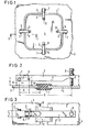
- a loading opening with approximately several square meters of opening area is closed by means of a plate 4 which forms the explosion closure plate according to the invention / innovation and also as a "hatch "can be designated.
- the outer edge of the plate 4 is inserted into a recess of the clamping profile 1, the opposite recess - as can be seen in particular from FIG. 2 - is pushed onto the edge 9 of the wall 3 delimiting the opening.
- the clamping profile 1 forms a seal in this closed position, so that rain or sea water cannot penetrate into the loading space covered by the plate 4.
- the clamping profile 1 holds the plate 4 in the desired position.
- the lever arm 2 is also a U-iron, but with the dimensions 40x60x40 mm, so that there is no clearance on both sides between the inside of the legs of the lever arm 2 and the outside of the legs of the bearing block 6.
- the leg height D of the bearing block 6 is therefore 40 mm.
- the distance G from the articulation point 7 to the edge 9 of the wall 3 delimiting the opening in this exemplary embodiment is approximately 12 cm.
- the width of the lever arm 2 is 60 mm and the width F of the pedestal 6 is 50 mm.
- the plate 4 is articulated on the side shown on the left with conventional joints on the wall 3, while it is only on the right side by means of the lever arm 2 and the same design as in FIG. 1 is torn open from the blocking position into the open position when a certain limit pressure is exceeded.
- the joints 10 ensure that the plate 4 is not thrown away, but remains on the wall 3.
- the bearing block 6 is fastened to the underside of the plate 4, so that the holding force can be adjusted via the lever arm 2 and the adjusting element 8 in that the screw forming the holding element 3 is pressed against the inside of the wall 3 and screwed in further the pressure intensifies becomes.
- the locking member 5 shears through, so that the lever arm 2 can be pivoted counterclockwise and the plate 4 can be torn out of the rubber-elastic clamping profile 1.
- the locking member 5 is arranged on the side opposite the adjusting member 8 from the articulation point 7 of the lever arm 2.
- the torque is determined by the distance A between the articulation point 7 and the locking member 5.
- the ratio of this distance A to the distance B also determines the force relationships between the force used to shear the locking member 5 and the pressure force acting on the plate 4 .
- the distance between the point of application of the setting element 8 on the plate 4 and the blocking element 5 or the articulation point 7 can be made adjustable.
Landscapes
- Engineering & Computer Science (AREA)
- Mechanical Engineering (AREA)
- Clamps And Clips (AREA)
- Pressure Vessels And Lids Thereof (AREA)
Applications Claiming Priority (2)
| Application Number | Priority Date | Filing Date | Title |
|---|---|---|---|
| DE3114941A DE3114941C2 (de) | 1981-04-13 | 1981-04-13 | Explosionsverschlußplatte |
| DE3114941 | 1981-04-13 |
Publications (2)
| Publication Number | Publication Date |
|---|---|
| EP0062696A1 true EP0062696A1 (fr) | 1982-10-20 |
| EP0062696B1 EP0062696B1 (fr) | 1985-02-13 |
Family
ID=6130068
Family Applications (1)
| Application Number | Title | Priority Date | Filing Date |
|---|---|---|---|
| EP81108575A Expired EP0062696B1 (fr) | 1981-04-13 | 1981-10-20 | Panneau de fermeture, notamment panneau de décompression |
Country Status (5)
| Country | Link |
|---|---|
| US (1) | US4656793A (fr) |
| EP (1) | EP0062696B1 (fr) |
| JP (1) | JPS57175589A (fr) |
| DE (1) | DE3114941C2 (fr) |
| SG (1) | SG35885G (fr) |
Cited By (3)
| Publication number | Priority date | Publication date | Assignee | Title |
|---|---|---|---|---|
| EP0092639A2 (fr) * | 1982-04-27 | 1983-11-02 | Jansens & Dieperink B.V. | Réservoirs empilables de grande capacité, en particulier silos |
| US4656793A (en) * | 1981-04-13 | 1987-04-14 | Jansens & Dieperink B.V. | Explosion cover plate especially explosion hatch |
| CN105041042A (zh) * | 2015-05-28 | 2015-11-11 | 何华明 | 锁芯钥匙双极限多码暗箱式机械防盗锁 |
Families Citing this family (25)
| Publication number | Priority date | Publication date | Assignee | Title |
|---|---|---|---|---|
| JPS60171799U (ja) * | 1984-04-25 | 1985-11-14 | 川崎重工業株式会社 | 小型舟艇のエンジンル−ムの耐圧機構 |
| DE3441957A1 (de) * | 1984-11-16 | 1986-05-28 | J. Derichs GmbH & Co KG Maschinen- und Mühlenbau, 5132 Übach-Palenberg | Zylindrischer silo |
| US4750303A (en) * | 1985-12-26 | 1988-06-14 | Mullen Terrance J | Silo explosion door |
| DE3715328C1 (de) * | 1987-05-08 | 1988-08-18 | Messerschmitt Boelkow Blohm | Dekompressionspanel |
| US5036632A (en) * | 1990-05-14 | 1991-08-06 | Bs&B Safety Systems, Inc. | Pressure relief panel assembly |
| BE1003900A6 (nl) * | 1990-10-02 | 1992-07-07 | Stuvex Internat Nv | Kleminrichting voor explosiepanelen. |
| DE19711208A1 (de) * | 1997-03-18 | 1998-09-24 | Rudolf Hajek | Druckentlastungsklappe |
| US6367203B1 (en) | 2000-09-11 | 2002-04-09 | Oklahoma Safety Equipment Co., Inc. | Rupture panel |
| US6318576B1 (en) | 2000-11-21 | 2001-11-20 | Oklahoma Safety Equipment Co., Inc. | Sanitary rupture disk apparatus |
| US7798893B2 (en) * | 2006-01-19 | 2010-09-21 | Fike Corporation | Full opening and reclosable explosion vent apparatus |
| US8322360B2 (en) | 2009-08-07 | 2012-12-04 | Oklahoma Safety Equipment Company, Inc. | Rupture panel |
| US8517042B2 (en) | 2009-08-27 | 2013-08-27 | Oklahoma Safety Equipment Company, Inc. | Rupture disk |
| NL2003649C2 (nl) * | 2009-10-16 | 2011-04-19 | Jansens & Dieperink Bv | Inrichting en werkwijze voor het positioneren van schaaldelen. |
| CA2968744C (fr) * | 2010-01-05 | 2020-03-24 | Cooper Technologies Company | Pinces pour caissons et systemes de pinces |
| US8602245B2 (en) | 2010-01-05 | 2013-12-10 | Cooper Technologies Company | Enclosure clamps and clamp systems |
| KR101763278B1 (ko) * | 2010-07-28 | 2017-07-31 | 볼보 컨스트럭션 이큅먼트 에이비 | 건설기계용 운전실 리어 유리 고정장치 |
| DE102011107984A1 (de) * | 2011-07-18 | 2013-01-24 | Roland Wolf | Druckentlastungsvorrichtung für einen Behälter |
| US9199789B2 (en) * | 2012-02-29 | 2015-12-01 | Fike Corporation | Explosion vent including buckle tab plate |
| CA2871881C (fr) | 2012-05-01 | 2020-06-30 | Cooper Technologies Company | Dispositifs de fixation pour enceintes antideflagrantes |
| CN104781155B (zh) | 2012-09-14 | 2017-04-19 | 库帕技术公司 | 用于防爆罩壳的紧固装置 |
| DE102013107559A1 (de) * | 2013-07-16 | 2015-01-22 | Maschinenfabrik Reinhausen Gmbh | Bersteinrichtung für ein Hochspannungsgerät |
| US9272821B2 (en) | 2013-09-13 | 2016-03-01 | Cooper Technologies Company | Fastening devices for explosion-proof enclosures |
| GB201720831D0 (en) * | 2017-10-12 | 2018-01-31 | Rolls-Royce Ltd | A pressure relief arrangement for a gas turbine engine |
| US10473436B2 (en) | 2017-11-08 | 2019-11-12 | Cubic Corporation | Blast resistant station fixed barrier |
| CN113624090B (zh) * | 2021-08-24 | 2022-09-23 | 中国商用飞机有限责任公司 | 防爆装置及飞行器 |
Citations (3)
| Publication number | Priority date | Publication date | Assignee | Title |
|---|---|---|---|---|
| FR1076435A (fr) * | 1953-04-24 | 1954-10-26 | Panneau de sécurité pour réservoirs à hydrocarbures | |
| FR2419444A1 (fr) * | 1978-03-08 | 1979-10-05 | Moss Rosenberg Verft As | Panneau de decompression, notamment pour cale de navire transportant du gaz |
| US4207706A (en) * | 1978-12-05 | 1980-06-17 | Haines Eugene F | Latch control for explosion relief panel |
Family Cites Families (5)
| Publication number | Priority date | Publication date | Assignee | Title |
|---|---|---|---|---|
| GB1284731A (en) * | 1968-05-18 | 1972-08-09 | Laing & Son Ltd John | Improvements in or relating to a building construction |
| JPS477467U (fr) * | 1971-02-20 | 1972-09-27 | ||
| US3807106A (en) * | 1973-04-16 | 1974-04-30 | Eastman Kodak Co | Explosion relief wall supporting fastener |
| US4109819A (en) * | 1977-05-16 | 1978-08-29 | The Stacey Manufacturing Co. | Explosion vent and method of venting |
| DE3114941C2 (de) * | 1981-04-13 | 1983-07-28 | Jansens & Dieperink B.V., 1505 Zaandam | Explosionsverschlußplatte |
-
1981
- 1981-04-13 DE DE3114941A patent/DE3114941C2/de not_active Expired
- 1981-06-25 US US06/277,249 patent/US4656793A/en not_active Expired - Fee Related
- 1981-10-20 EP EP81108575A patent/EP0062696B1/fr not_active Expired
-
1982
- 1982-01-11 JP JP57002634A patent/JPS57175589A/ja active Granted
-
1985
- 1985-05-11 SG SG358/85A patent/SG35885G/en unknown
Patent Citations (3)
| Publication number | Priority date | Publication date | Assignee | Title |
|---|---|---|---|---|
| FR1076435A (fr) * | 1953-04-24 | 1954-10-26 | Panneau de sécurité pour réservoirs à hydrocarbures | |
| FR2419444A1 (fr) * | 1978-03-08 | 1979-10-05 | Moss Rosenberg Verft As | Panneau de decompression, notamment pour cale de navire transportant du gaz |
| US4207706A (en) * | 1978-12-05 | 1980-06-17 | Haines Eugene F | Latch control for explosion relief panel |
Cited By (5)
| Publication number | Priority date | Publication date | Assignee | Title |
|---|---|---|---|---|
| US4656793A (en) * | 1981-04-13 | 1987-04-14 | Jansens & Dieperink B.V. | Explosion cover plate especially explosion hatch |
| EP0092639A2 (fr) * | 1982-04-27 | 1983-11-02 | Jansens & Dieperink B.V. | Réservoirs empilables de grande capacité, en particulier silos |
| EP0092639A3 (en) * | 1982-04-27 | 1984-11-14 | Jansens & Dieperink B.V. | Large capacity stackable containers, in particular silos |
| CN105041042A (zh) * | 2015-05-28 | 2015-11-11 | 何华明 | 锁芯钥匙双极限多码暗箱式机械防盗锁 |
| CN105041042B (zh) * | 2015-05-28 | 2017-10-27 | 何华明 | 锁芯钥匙双极限多码暗箱式机械防盗锁 |
Also Published As
| Publication number | Publication date |
|---|---|
| US4656793A (en) | 1987-04-14 |
| EP0062696B1 (fr) | 1985-02-13 |
| JPS57175589A (en) | 1982-10-28 |
| DE3114941C2 (de) | 1983-07-28 |
| SG35885G (en) | 1985-11-15 |
| JPS6152073B2 (fr) | 1986-11-11 |
| DE3114941A1 (de) | 1982-10-28 |
Similar Documents
| Publication | Publication Date | Title |
|---|---|---|
| EP0062696B1 (fr) | Panneau de fermeture, notamment panneau de décompression | |
| EP0071077A1 (fr) | Toit de véhicule ayant une ouverture à fermer au moyen d'un couvercle | |
| EP1354545B1 (fr) | Joint pour une cloison de séparation de douche | |
| CH677388A5 (fr) | ||
| EP0581011B1 (fr) | Récipient avec dispositif d'équilibrage de pression | |
| DE69102680T2 (de) | Scharnier geeignet zur Anwendung in einer Dachlukenmontage. | |
| DE3126432C2 (fr) | ||
| DE3840240A1 (de) | Druckentlastungseinrichtung an gebaeuden, insbesondere elektrischen schaltwerken | |
| EP0505350B1 (fr) | Disque pivotant-séquence de fermeture et dispositif de verrouillage | |
| EP0092639B1 (fr) | Réservoirs empilables de grande capacité, en particulier silos | |
| DE2131852C3 (de) | Klappenscharnier | |
| DE2136376C2 (de) | Ausstellvorrichtung zum Feststellen eines schwenkbaren Dachlukendeckels, insbesondere für Fahrzeuge | |
| DE69304940T2 (de) | Selbsttätig schliessendes Bodentor | |
| DE2229348A1 (de) | Verbergbares Scharnierteil, insbesondere für Möbel | |
| CH407189A (de) | Kühlschrank | |
| DE9307870U1 (de) | Schwenk-Hebescharnier | |
| DE68904563T2 (de) | Fenster mit oben angelenktem rahmen fuer den einbau in schraegdaechern. | |
| DE8602948U1 (de) | Vorrichtung zum Ausgleich von Druckunterschieden, insbesondere in Silos | |
| DE3414826C2 (de) | Silobehälter | |
| DE8905142U1 (de) | Gebäudeaußentür | |
| DE2651824B1 (de) | Verschluss fuer eine verschwenkbare sicherheitsklappe, insbesondere an einem kraftwerksgebaeude | |
| DE7802906U1 (de) | Tuerstopper | |
| DE1273366B (de) | Lager fuer um eine mittlere waagerechte Achse schwingbare Fluegel von schraeg geneigten Fenstern | |
| DE29509177U1 (de) | Türband | |
| DE2634707A1 (de) | Krankentransportfahrzeug mit als waagerecht geteilter klappe ausgebildeter hinterer ladetuer |
Legal Events
| Date | Code | Title | Description |
|---|---|---|---|
| PUAI | Public reference made under article 153(3) epc to a published international application that has entered the european phase |
Free format text: ORIGINAL CODE: 0009012 |
|
| AK | Designated contracting states |
Designated state(s): BE FR GB IT NL |
|
| 17P | Request for examination filed |
Effective date: 19830105 |
|
| ITF | It: translation for a ep patent filed | ||
| GRAA | (expected) grant |
Free format text: ORIGINAL CODE: 0009210 |
|
| AK | Designated contracting states |
Designated state(s): BE FR GB IT NL |
|
| ET | Fr: translation filed | ||
| PLBE | No opposition filed within time limit |
Free format text: ORIGINAL CODE: 0009261 |
|
| STAA | Information on the status of an ep patent application or granted ep patent |
Free format text: STATUS: NO OPPOSITION FILED WITHIN TIME LIMIT |
|
| 26N | No opposition filed | ||
| ITTA | It: last paid annual fee | ||
| PGFP | Annual fee paid to national office [announced via postgrant information from national office to epo] |
Ref country code: GB Payment date: 19970806 Year of fee payment: 17 |
|
| PGFP | Annual fee paid to national office [announced via postgrant information from national office to epo] |
Ref country code: FR Payment date: 19970818 Year of fee payment: 17 |
|
| PGFP | Annual fee paid to national office [announced via postgrant information from national office to epo] |
Ref country code: BE Payment date: 19971021 Year of fee payment: 17 |
|
| PGFP | Annual fee paid to national office [announced via postgrant information from national office to epo] |
Ref country code: NL Payment date: 19971029 Year of fee payment: 17 |
|
| PG25 | Lapsed in a contracting state [announced via postgrant information from national office to epo] |
Ref country code: GB Free format text: LAPSE BECAUSE OF NON-PAYMENT OF DUE FEES Effective date: 19981020 |
|
| PG25 | Lapsed in a contracting state [announced via postgrant information from national office to epo] |
Ref country code: BE Free format text: LAPSE BECAUSE OF NON-PAYMENT OF DUE FEES Effective date: 19981031 |
|
| BERE | Be: lapsed |
Owner name: JANSENS & DIEPERINK B.V. Effective date: 19981031 |
|
| PG25 | Lapsed in a contracting state [announced via postgrant information from national office to epo] |
Ref country code: NL Free format text: LAPSE BECAUSE OF NON-PAYMENT OF DUE FEES Effective date: 19990501 |
|
| GBPC | Gb: european patent ceased through non-payment of renewal fee |
Effective date: 19981020 |
|
| PG25 | Lapsed in a contracting state [announced via postgrant information from national office to epo] |
Ref country code: FR Free format text: LAPSE BECAUSE OF NON-PAYMENT OF DUE FEES Effective date: 19990630 |
|
| NLV4 | Nl: lapsed or anulled due to non-payment of the annual fee |
Effective date: 19990501 |
|
| REG | Reference to a national code |
Ref country code: FR Ref legal event code: ST |