EP0062696A1 - Closing panel, especially explosion relief panel - Google Patents
Closing panel, especially explosion relief panel Download PDFInfo
- Publication number
- EP0062696A1 EP0062696A1 EP81108575A EP81108575A EP0062696A1 EP 0062696 A1 EP0062696 A1 EP 0062696A1 EP 81108575 A EP81108575 A EP 81108575A EP 81108575 A EP81108575 A EP 81108575A EP 0062696 A1 EP0062696 A1 EP 0062696A1
- Authority
- EP
- European Patent Office
- Prior art keywords
- wall
- lever arm
- explosion
- closure plate
- articulation point
- Prior art date
- Legal status (The legal status is an assumption and is not a legal conclusion. Google has not performed a legal analysis and makes no representation as to the accuracy of the status listed.)
- Granted
Links
- 238000004880 explosion Methods 0.000 title claims abstract description 27
- 230000009975 flexible effect Effects 0.000 claims description 2
- 238000010008 shearing Methods 0.000 claims description 2
- 238000007789 sealing Methods 0.000 abstract description 4
- 230000000903 blocking effect Effects 0.000 description 3
- 230000000694 effects Effects 0.000 description 3
- 238000011161 development Methods 0.000 description 2
- 230000018109 developmental process Effects 0.000 description 2
- 239000000428 dust Substances 0.000 description 2
- 239000002360 explosive Substances 0.000 description 2
- XEEYBQQBJWHFJM-UHFFFAOYSA-N iron Substances [Fe] XEEYBQQBJWHFJM-UHFFFAOYSA-N 0.000 description 2
- 229910052742 iron Inorganic materials 0.000 description 2
- 230000007704 transition Effects 0.000 description 2
- XAGFODPZIPBFFR-UHFFFAOYSA-N aluminium Chemical compound [Al] XAGFODPZIPBFFR-UHFFFAOYSA-N 0.000 description 1
- 229910052782 aluminium Inorganic materials 0.000 description 1
- 230000005540 biological transmission Effects 0.000 description 1
- 239000000463 material Substances 0.000 description 1
- 238000012986 modification Methods 0.000 description 1
- 230000004048 modification Effects 0.000 description 1
- NJPPVKZQTLUDBO-UHFFFAOYSA-N novaluron Chemical compound C1=C(Cl)C(OC(F)(F)C(OC(F)(F)F)F)=CC=C1NC(=O)NC(=O)C1=C(F)C=CC=C1F NJPPVKZQTLUDBO-UHFFFAOYSA-N 0.000 description 1
- 239000004033 plastic Substances 0.000 description 1
- 239000013535 sea water Substances 0.000 description 1
Images

Classifications
-
- B—PERFORMING OPERATIONS; TRANSPORTING
- B65—CONVEYING; PACKING; STORING; HANDLING THIN OR FILAMENTARY MATERIAL
- B65D—CONTAINERS FOR STORAGE OR TRANSPORT OF ARTICLES OR MATERIALS, e.g. BAGS, BARRELS, BOTTLES, BOXES, CANS, CARTONS, CRATES, DRUMS, JARS, TANKS, HOPPERS, FORWARDING CONTAINERS; ACCESSORIES, CLOSURES, OR FITTINGS THEREFOR; PACKAGING ELEMENTS; PACKAGES
- B65D90/00—Component parts, details or accessories for large containers
- B65D90/22—Safety features
- B65D90/32—Arrangements for preventing, or minimising the effect of, excessive or insufficient pressure
- B65D90/36—Weakened parts
Definitions
- the invention / innovation is that the clamping profile is bridged by at least one lever arm, one side of which is articulated on the wall - or the plate - and the other side is then supported on the plate - or the wall or the clamping profile , If a locking member, which is designed in particular as a shear pin and which prevents pivoting of the lever arm around the articulation point in the closed position, by the occurrence of the determined overpressure or underpressure. Shearing a pivoting of the lever arm around the articulation point allowed.
- the holding pressure which holds the plate in the opening of the wall, is no longer transmitted in the invention / innovation only by the seal, which is in particular made of rubber or rubber-elastic plastic and is designed as a clamping profile. Rather, the lever arm serves for additional support of the plate. In order to be able to set this support force well, it is recommended according to a special embodiment of the invention / innovation to equip the lever arm on the side facing away from the articulation point with an adjusting element, in particular a screw, the tip or the screw head of which is on the outside of the plate can put on. By adjusting the screw, the transmission pressure from the lever arm to the plate can also be changed, since the clamping profile of the seal can be bent due to its flexible properties and the plate can be deflected somewhat from the normal stop.
- an adjusting element in particular a screw
- the plate is given the possibility of evading in the direction of the lever arm and guessing out of the clamping profile or pushing the clamping profile out of its mounting in the wall in order to enable pressure equalization.
- the "explosive force" which must be achieved in order to put the locking member out of operation can be set accordingly by a suitable choice of the design and the material of the locking member, in particular a shear pin, and by a suitable choice of the distance thereof from the articulation point. In order to obtain adjustability in this regard, it is advisable to make the distance from the locking member to the articulation point changeable.
- a loading opening with approximately several square meters of opening area is closed by means of a plate 4 which forms the explosion closure plate according to the invention / innovation and also as a "hatch "can be designated.
- the outer edge of the plate 4 is inserted into a recess of the clamping profile 1, the opposite recess - as can be seen in particular from FIG. 2 - is pushed onto the edge 9 of the wall 3 delimiting the opening.
- the clamping profile 1 forms a seal in this closed position, so that rain or sea water cannot penetrate into the loading space covered by the plate 4.
- the clamping profile 1 holds the plate 4 in the desired position.
- the lever arm 2 is also a U-iron, but with the dimensions 40x60x40 mm, so that there is no clearance on both sides between the inside of the legs of the lever arm 2 and the outside of the legs of the bearing block 6.
- the leg height D of the bearing block 6 is therefore 40 mm.
- the distance G from the articulation point 7 to the edge 9 of the wall 3 delimiting the opening in this exemplary embodiment is approximately 12 cm.
- the width of the lever arm 2 is 60 mm and the width F of the pedestal 6 is 50 mm.
- the plate 4 is articulated on the side shown on the left with conventional joints on the wall 3, while it is only on the right side by means of the lever arm 2 and the same design as in FIG. 1 is torn open from the blocking position into the open position when a certain limit pressure is exceeded.
- the joints 10 ensure that the plate 4 is not thrown away, but remains on the wall 3.
- the bearing block 6 is fastened to the underside of the plate 4, so that the holding force can be adjusted via the lever arm 2 and the adjusting element 8 in that the screw forming the holding element 3 is pressed against the inside of the wall 3 and screwed in further the pressure intensifies becomes.
- the locking member 5 shears through, so that the lever arm 2 can be pivoted counterclockwise and the plate 4 can be torn out of the rubber-elastic clamping profile 1.
- the locking member 5 is arranged on the side opposite the adjusting member 8 from the articulation point 7 of the lever arm 2.
- the torque is determined by the distance A between the articulation point 7 and the locking member 5.
- the ratio of this distance A to the distance B also determines the force relationships between the force used to shear the locking member 5 and the pressure force acting on the plate 4 .
- the distance between the point of application of the setting element 8 on the plate 4 and the blocking element 5 or the articulation point 7 can be made adjustable.
Landscapes
- Engineering & Computer Science (AREA)
- Mechanical Engineering (AREA)
- Clamps And Clips (AREA)
- Pressure Vessels And Lids Thereof (AREA)
Abstract
Um das selbsttätige Öffnen von Explosions-Verschlußplatten (4) bei bestimmten Druckdifferenzen genauer einstellen zu können, ist die Verschlußplatte (4) nicht nur in einem gummielastischen Dichtungs-Klemmprofil (1) gehaltert, sondern zusätzlich durch mindestens ein Gegenlager (2) abgestützt, das aus einem Hebelarm (2) gebildet ist, der bei Überschreiten der Grenzbelastung aus seiner Abstützlage ausschwenkt (7).In order to be able to set the automatic opening of explosion closure plates (4) more precisely at certain pressure differences, the closure plate (4) is not only held in a rubber-elastic sealing clamping profile (1), but is additionally supported by at least one counter bearing (2) which is formed from a lever arm (2) which swings out of its support position when the limit load is exceeded (7).
Description
Die Erfindung/Neuerung betrifft eine Explosions-Verschlußplatte, insbesondere Explosions-Luke, der im Oberbegriff des Anspruches 1 genannten Gattung.The invention / innovation relates to an explosion closure plate, in particular explosion hatch, of the type mentioned in the preamble of
Derartige Explosions-Verschlußplatten sind bereits bekannt (VDI Richtlinien 3673 Über Druckentlastung von Staubexplosionen vom Juni 1979, S.5/6). Dabei wird die scheibenartige Verschlußplatte in einem Gummiklemmprofil gehalten. Bei Erreichen eines nicht mehr zulässigen Überdrucks in einem mit der Verschlußplatte verschlossenen Behälter wird die Scheibe insbesondere explosionsartig aus dem Klemmprofil herausgedrückt. Dabei ist es auch bekannt, solche Scheiben ähnlich wie Explosionsklappen zu haltern, um sie am Wegfliegen zu hindern.Such explosion sealing plates are already known (VDI guidelines 3673 on pressure relief from dust explosions of June 1979, p.5 / 6). The disc-like closure plate is held in a rubber clamping profile. When an overpressure in a container closed with the closure plate is no longer permissible, the pane is pressed out of the clamping profile in an explosive manner. It is also known to hold such disks similar to explosion flaps in order to prevent them from flying away.
Derartige Explosions-Verschlußplatten sind insbesondere bei Anlagen anwendbar, bei denen mit Staubexplosionen zu rechnen ist. Ihre ventilartige Wirkung soll verhindern, daß durch einen bestimmten Überdruck Anlagenteile an unerwünschten Stellen zerrissen oder beschädigt werden. Die Explosions-Verschlußklappen stellen die "schwächsten" Stellen der Anlage bzw. des Behälters oder der Wand dar, so daß sich der Überdruck dort auszugleichen vermag. Entsprechend sind solche Explosions-Verschlußplatten auch bei Einrichtungen anwendbar, bei denen mit unerwünschten Unterdrucken zu rechnen ist.Explosion sealing plates of this type can be used in particular in systems in which dust explosions are to be expected. Their valve-like effect is intended to prevent plant parts from being torn or damaged at undesired locations by a certain excess pressure. The explosion flaps represent the "weakest" points of the system or the container or the wall, so that the overpressure can compensate for them there. Correspondingly, such explosion sealing plates can also be used in facilities in which undesirable negative pressure is to be expected.
Es hat sich jedoch gezeigt, daß der Druck, bei dem die "Entlastung" stattfinden soll, recht schwierig einstellbar ist, insbesondere wenn die Plattengröße einen Bereich in der Größenordnung von 1qm erreicht.However, it has been found that the pressure at which the "relief" is to take place is very difficult to set, especially when the plate size reaches a range of the order of 1 square meter.
Der Erfindung/Neuerung liegt daher die Aufgabe zugrunde, die Explosions-Verschlußplatte der eingangs genannten Gattung dahingehend zu verbessern, daß trotz konstruktiv einfacher Gestaltung eine bessere Einstellbarkeit auf das Ansprechen bzw. den bestimmten Über- oder Unterdruck möglich ist.The invention / innovation is therefore based on the object of improving the explosion closure plate of the type mentioned in such a way that, despite the simple design, a better adjustability to the response or the specific positive or negative pressure is possible.
Die Erfindung/Neuerung besteht darin, daß das Klemmprofil mindestens von einem Hebelarm überbrückt ist, von dem eine Seite an der Wand - oder der Platte - angelenkt ist und sich die andere Seite an der Platte - bzw. der Wand bzw. dem Klemmprofil dann abstützt, wenn ein Sperrorgan, das insbesondere als Scherstift ausgebildet ist und das in der Verschlußstellung ein Schwenken des Hebelarmes um die Anlenkstelle verhindert, bei Auftreten des bestimmten Über- bzw. Unterdruckes durch. Abscheren ein Schwenken des Hebelarmes um die Anlenkstelle jedoch erlaubt.The invention / innovation is that the clamping profile is bridged by at least one lever arm, one side of which is articulated on the wall - or the plate - and the other side is then supported on the plate - or the wall or the clamping profile , If a locking member, which is designed in particular as a shear pin and which prevents pivoting of the lever arm around the articulation point in the closed position, by the occurrence of the determined overpressure or underpressure. Shearing a pivoting of the lever arm around the articulation point allowed.
Der Haltedruck, der die Platte in der Öffnung der Wand hält, wird bei der Erfindung/Neuerung nicht mehr nur durch die insbesondere aus Gummi oder gummielastischem Kunststoff bestehende und als Klemmprofil ausgebildete Dichtung übertragen. Vielmehr dient der Hebelarm zur zusätzlichen Abstützung der Platte. Um diese Abstützkraft gut einstellen zu können, empfiehlt es sich nach einer besonderen Ausbildung der Erfindung/Neuerung, den Hebelarm an der der Anlenkstelle abgewandten Seite mit einem Einstellorgan, insbesondere einer Schraube, auszurüsten, deren Spitze oder auch deren Schraubkopf sich an die Außenseite der Platte anlegen läßt. Durch Verstellen der Schraube kann auch der Übertragungsdruck vom Hebelarm auf die Platte verändert werden, da das Klemmprofil der Dichtung aufgrund seiner biegeelastischen Eigenschaften biegbar ist und die Platte aus der normalen Haltestelle etwas ausgelenkt werden kann.The holding pressure, which holds the plate in the opening of the wall, is no longer transmitted in the invention / innovation only by the seal, which is in particular made of rubber or rubber-elastic plastic and is designed as a clamping profile. Rather, the lever arm serves for additional support of the plate. In order to be able to set this support force well, it is recommended according to a special embodiment of the invention / innovation to equip the lever arm on the side facing away from the articulation point with an adjusting element, in particular a screw, the tip or the screw head of which is on the outside of the plate can put on. By adjusting the screw, the transmission pressure from the lever arm to the plate can also be changed, since the clamping profile of the seal can be bent due to its flexible properties and the plate can be deflected somewhat from the normal stop.
Wird jedoch der Druckunterschied zwischen Außen- und Innenseite der Platte bzw. des von der Platte verschlossenen Raumes zu groß, dann kann diese Kraft von dem Hebelarm bzw. dem Sperrorgan nicht mehr aufgenommen werden; dieses fällt dann hinsichtlich seiner Sperrwirkung aus und erlaubt dem Hebelarm, sich um die Anlenkstelle zu verschwenken. Hierdurch wird der Platte die Möglichkeit gegeben, in Richtung zum Hebelarm auszuweichen und aus dem Klemmprofil herauszugeraten bzw. das Klemmprofil aus seiner Lagerung in der Wand herauszudrücken, um den Druckausgleich zu ermöglichen.However, if the pressure difference between the outside and inside of the plate or the space closed by the plate becomes too large, then this force can no longer be absorbed by the lever arm or the locking member; This then fails in terms of its locking effect and allows the lever arm to pivot around the articulation point. As a result, the plate is given the possibility of evading in the direction of the lever arm and guessing out of the clamping profile or pushing the clamping profile out of its mounting in the wall in order to enable pressure equalization.
Durch geeignete Wahl der Ausbildung und des Werkstoffs des insbesondere als Scherstift ausgebildeten Sperrorgans sowie durch geeignete Wahl des Abstands desselben von der Anlenkstelle kann die "Sprengkraft" entsprechend eingestellt werden, die erreicht werden muß, um das Sperrorgan außer Funktion zu setzen. Um auch diesbezüglich eine Einstellbarkeit zu erhalten, empfiehlt es sich, den Abstand vom Sperrorgan zur Anlenkstelle veränderbar zu machen.The "explosive force" which must be achieved in order to put the locking member out of operation can be set accordingly by a suitable choice of the design and the material of the locking member, in particular a shear pin, and by a suitable choice of the distance thereof from the articulation point. In order to obtain adjustability in this regard, it is advisable to make the distance from the locking member to the articulation point changeable.
Weitere Ausbildungen der Erfindung/Neuerung sind in den Unteransprüchen beansprucht und werden im folgenden anhand der Zeichnung noch näher erläutert. Dabei zeigen:
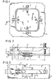
- Fig. 1 eine schematische Teilaufsicht auf einen Schiffsladeraum, der mit einer Explosions-Verschlußluke verschlossen ist;
- Fig. 2 eine Seitenansicht teilweise im Querschnitt längs der Schnittlinien I - I von Fig. 1;
- Fig. 3 eine Aufsicht - teilweise aufgebrochen - auf den Bereich des Hebelarms und der entsprechenden Übergangsstelle von der Wand über das Klemmprofil zur Platte;
- Fig. 4 eine andere Ausbildung der Erfindung/Neuerung, und zwar wiederum entsprechend Fig. 1 als Teilausschnitt der Aufsicht auf eine Explosions-Verschlußtür;
- Fig. 5 einen Querschnitt durch die Übergangsstelle von der Wand über das Klemmprofil zur Platte mit einer anderen Ausbildung des Hebelarms in Seitenansicht und
- Fig. 6 eine Teilaufsicht auf den Bereich der Anlenkstelle der Ausbildung gemäß Fig. 5.
- Figure 1 is a schematic partial plan view of a ship's hold, which is closed with an explosion hatch.
- FIG. 2 is a side view, partly in cross section, along the section lines I - I of FIG. 1;
- Figure 3 is a plan view - partially broken away - of the area of the lever arm and the corresponding transition point from the wall via the clamping profile to the plate;
- Fig. 4 shows another embodiment of the invention / innovation, again in accordance with Figure 1 as a partial section of the supervision of an explosion lock door.
- Fig. 5 shows a cross section through the transition point from the wall via the clamping profile to the plate with a different design of the lever arm in side view
- 6 is a partial view of the area of the articulation point of the design according to FIG. 5.
Gemäß Fig. 1 ist auf der Wand 3, beispielsweise einem Schiffsdeck, das einen Laderaum nach oben abschließt, eine Ladeöffnung mit etwa mehreren Quadratmetern Öffnungsfläche mittels einer Platte 4 verschlossen, die die Explosions-Verschlußplatte gemäß der Erfindung/Neuerung bildet und auch als "Luke" bezeichnet werden kann. Der Außenrand der Platte 4 ist in eine Aussparung des Klemmprofils 1 eingesetzt, dessen entgegengesetzte Aussparung - wie insbesondere aus Fig. 2 ersichtlich ist - auf den die Öffnung begrenzenden Rand 9 der Wand 3 aufgesteckt ist. Das Klemmprofil 1 bildet in dieser Verschlußstellung eine Dichtung, so daß Regen- oder Seewasser nicht in den von der Platte 4 abgedeckten Laderaum eindringen kann. Außerdem hält das Klemmprofil 1 die Platte 4 in der gewünschten Stellung fest.According to FIG. 1, on the wall 3, for example a ship's deck, which closes off a loading space at the top, a loading opening with approximately several square meters of opening area is closed by means of a plate 4 which forms the explosion closure plate according to the invention / innovation and also as a "hatch "can be designated. The outer edge of the plate 4 is inserted into a recess of the
Über diese eine bekannte Anordnung darstellende Halterung der Platte 4 hinaus wird diese jedoch noch mittels des Hebelarmes 2 abgestützt, der an seinem in Fig. 2 links dargestellten Ende mittels eines Schraubbolzens an der Anlenkstelle 7 an einem im Querschnitt U-förmigen Lagerbock 6 angelenkt ist, dessen Stegteil an die Wand 3 angeschweißt ist. Am entgegengesetzten Ende ist der Hebelarm 2 mit einem Einstellorgan 8 versehen, das als Schraube ausgebildet ist und dessen freies Ende an die Außenseite der Platte 4 andrehbar ist. Der Abstand G von der Oberkante des Hebelarmes 2 bis zur Außenseite der Platte 4 kann nun durch Verschrauben der Schraube, d.h. des Einstellorgans 8, geändert werden. Damit bei einer solchen Änderung des Abstandes C auch Kräfte über den Hebelarm 2 auf die Platte 4 übertragen werden können, ist der Hebelarm 2 im Abstand A von der Anlenkstelle 7 mittels eines als Sperrorgan 5 dienenden Scherstiftes zusätzlich mit dem Lagerbock 6 verbunden. Dieser Abstand A beträgt beispielsweise 70 mm, bei einem Abstand B von der Angriffsstelle des Einstellorgans 8 an der Platte 4 bis zur Anlenkstelle 7 von etwa 30 cm. Als Einstellorgan 8 dient beispielsweise eine Schraube mit dem Gewinde M 12, während der Scherstift aus Aluminium mit einem Durchmesser von 6 mm besteht. Der Lagerbock 6 ist ein U-Eisen mit einer Dicke von 4 mm und den Abmessungen 40x50x40 mm. Der Hebelarm 2 ist ebenfalls ein U-Eisen, jedoch mit den Abmessungen 40x60x40 mm, so daß zwischen den Innenseiten der Schenkel des Hebelarms 2 und den Außenseiten der Schenkel des Lagerbocks 6 kein Spielraum an beiden Seiten besteht. Die Schenkelhöhe D des Lagerbockes 6 ist daher 40 mm. Der Abstand G von der Anlenkstelle 7 bis zum die Öffnung begrenzenden Rand 9 der Wand 3 beträgt bei diesem Ausführungsbeispiel etwa 12 cm. Die Breite des Hebelarmes 2 beträgt 60 mm und die Breite F des Lagerbockes 6 50 mm.In addition to this mounting of the plate 4, which is a known arrangement, it is also supported by means of the lever arm 2, which is articulated at its end shown on the left in FIG. whose web part is welded to the wall 3. At the opposite end, the lever arm 2 is provided with an adjusting element 8, which is designed as a screw and whose free end can be turned to the outside of the plate 4. The distance G from the upper edge of the lever arm 2 to the outside of the plate 4 can now be changed by screwing the screw, ie the adjusting element 8. So that with such a change in the distance C, forces can also be transmitted to the plate 4 via the lever arm 2, the lever arm 2 is additionally connected to the
Wird der Druck im Innenraum, d.h. unterhalb der Platte 4 unzulässig groß, dann wird eine so große Kraft von der Platte 4 über das Einstellorgan 8 und dem Hebelarm 2 sowie das Sperrorgan 5 auf den Lagerbock 6 und die Wand 3 übertragen, daß bei Erreichen bzw. Überschreiten eines Grenzwertes der Scherstift bzw. das Sperrorgan 5 durchschert und der Hebelarm 2 seine Sperrstellung verläßt und um die Anlenkstelle 7 verschwenken kann. Hierdurch kann der Hebelarm 2 keine Kraft mehr auf die Platte 4 übertragen, so daß diese aus dem Klemmprofil 1 bzw. dieses aus der Wand 3 herausgerissen wird. Die "Ventilwirkung" der Explosions-Verschlußluke ist hierdurch gewährleistet.If the pressure in the interior, i.e. underneath the plate 4 inadmissibly large, then such a large force is transmitted from the plate 4 via the adjusting element 8 and the lever arm 2 and the blocking
Bei der anderen Ausbildung der Erfindung/Neuerung gemäß Fig. 4 ist die Platte 4 an der links dargestellten Seite mit üblichen Gelenken an der Wand 3 angelenkt, während sie nur an der rechten Seite mittels des Hebelarms 2 und im übrigen derselben Ausbildung wie nach Fig. 1 bei Überschreiten eines bestimmten Grenzdruckes aus der Sperrstellung in die geöffnete Stellung aufgerissen wird. Die Gelenke 10 sorgen dafür, daß die Platte 4 nicht hinweggeschleudert wird, sondern an der Wand 3 verbleibt.In the other embodiment of the invention / innovation according to FIG. 4, the plate 4 is articulated on the side shown on the left with conventional joints on the wall 3, while it is only on the right side by means of the lever arm 2 and the same design as in FIG. 1 is torn open from the blocking position into the open position when a certain limit pressure is exceeded. The
Gemäß Fig. 5 ist der Lagerbock 6 an der Unterseite der Platte 4 befestigt, so daß die Haltekraft über den Hebelarm 2 und das Einstellorgan 8 dadurch einstellbar ist, daß die das Halteorgan 3 bildende Schraube an die Innenseite der Wand 3 angedrückt und durch weiteres Einschrauben der Druck verstärkt wird. Im Falle von Überschreiten des eingestellten Grenzdruckes schert das Sperrorgan 5 durch, so daß der Hebelarm 2 im Gegenuhrzeigersinn verschwenkt und die Platte 4 aus dem gummielastischen Klemmprofil 1 herausgerissen werden kann. Im Unterschied zur Ausbildung nach den Fig. 1 bis 4 ist bei der Ausbildung von Fig. 5 und 6 das Sperrorgan 5 an der dem Einstellorgan 8 entgegengesetzten Seite von der Anlenkstelle 7 des Hebelarms 2 angeordnet. Auch hier wird jedoch das Drehmoment bestimmt vom Abstand A zwischen der Anlenkstelle 7 und dem Sperrorgan 5. Das Verhältnis dieses Abstands A zum Abstand B bestimmt auch die Kräfteverhältnisse zwischen dem zum Abscheren des Sperrorgans 5 dienenden Kraft und der Druckkraft, die auf die Platte 4 wirkt.5, the
Es versteht sich, daß weitere Abwandlungen und Ausbildungen der Erfindung/Neuerung im Rahmen des hier beschriebenen Prinzips möglich sind. So ist dieses Prinzip anwendbar bei vielfältigen Behälter- und Raumtypen sowie vielfältigen Ausbildungen von Verschlußplatten, Verschlußdeckeln und dergleichen.It goes without saying that further modifications and developments of the invention / innovation are possible within the framework of the principle described here. So this principle is applicable to a wide variety of container and room types as well as various designs of closure plates, closure lids and the like.
Außerdem kann auch der Abstand zwischen dem Angriffspunkt des Einstellorgans 8 auf der Platte 4 und dem Sperrorgan 5 bzw. der Anlenkstelle 7 verstellbar gemacht werden.In addition, the distance between the point of application of the setting element 8 on the plate 4 and the
Claims (10)
dadurch gekennzeichnet,
daß das Klemmprofil (1) mindestens von einem Hebelarm (2)' überbrückt ist, von dem eine Seite an der Wand (3) oder der Platte (4) angelenkt ist und sich die andere Seite an der Platte (4) bzw. der Wand (3) dann abstützt, wenn ein Sperrorgan (5), das in der Verschlußstellung ein Schwenken des Hebelarms (2) um die Anlenkstelle verhindert, beim Auftreten des bestimmten Über- bzw. Unterdruckes durch Abscheren ein Schwenken des Hebelarms (2) um die Anlenkstelle jedoch erlaubt.1. Explosion closure plate, in particular explosion hatch, which can be inserted tightly into an opening in a wall of a room to be closed, for example silos, by means of flexible, elastic clamping profiles and, when a certain excess and / or negative pressure occurs in the room, at least partially opening the opening can be pushed out of the wall or the clamping profile,
characterized,
that the clamping profile (1) is bridged by at least one lever arm (2) ', one side of which is articulated on the wall (3) or the plate (4) and the other side on the plate (4) or the wall (3) then supports when a locking member (5), which prevents the lever arm (2) from pivoting around the articulation point in the closed position, when the specific overpressure or underpressure occurs by shearing a pivoting of the lever arm (2) around the articulation point however allowed.
daß das Sperrorgan (5) als Scherstift ausgebildet ist.2. Explosion closure plate according to claim 1, characterized in
that the locking member (5) is designed as a shear pin.
daß an der Wand (3) in der Nähe des Klemmprofils (1) ein Lagerbock (6) befestigt ist, der sowohl die Anlenkstelle in Form eines Schwenklagers (7) als auch die Lagerung für das Sperrorgan (5) aufweist.3. Explosion closure plate according to claim 1 or 2, characterized in
that on the wall (3) in the vicinity of the clamping profile (1) a bearing block (6) is fixed, which has both the articulation point in the form of a pivot bearing (7) and the storage for the locking member (5).
daß der Lagerbock (6) als U-Profil ausgebildet und außen an der Wand angeschweißt ist.4. Explosion closure flap according to claim 3, characterized in
that the bearing block (6) is designed as a U-profile and is welded to the outside of the wall.
daß der Hebelarm (2) aus einem U-Profil hergestellt ist.5. Explosion closure plate according to one of the preceding claims, characterized in
that the lever arm (2) is made from a U-profile.
daß an der der Anlenkstelle abgewandten Seite des Hebelarms (2) ein Einstellorgan (8) angeordnet ist, das einstellbar an die Platte (4) bzw. an die Wand (3) andrückbar ist.6. Explosion closure plate according to one of the preceding claims, characterized in
that an adjusting member (8) is arranged on the side of the lever arm (2) facing away from the articulation point, which can be pressed against the plate (4) or against the wall (3).
daß für das Einstellorgan (8) eine Schraube verwendet ist.7. Explosion closure plate according to claim 6, characterized in
that a screw is used for the adjusting member (8).
daß der Abstand A in Längsrichtung des Hebelarms (2) von der Anlenkstelle zum Sperrorgan (5) wesentlich geringer ist als der Abstand B von der Anlenkstelle zum Einstellorgan (8).8. Explosion closure plate according to claim 6 or 7, characterized in
that the distance A in the longitudinal direction of the lever arm (2) from the articulation point to the locking member (5) is significantly less than the distance B from the articulation point to the adjusting member (8).
daß das Verhältnis der Abstände B:A etwa 4:1 bis 5:1 beträgt.9. Explosion closure plate according to claim 8, characterized in
that the ratio of the distances B: A is about 4: 1 to 5: 1.
daß der Abstand G von der Anlenkstelle zu dem vom Klemmprofil (1) überdeckten Rand (9) der Wand (3) etwa das Doppelte wie der Abstand A beträgt.10. Explosion closure plate according to claim 8 or 9, characterized in
that the distance G from the articulation point to the edge (9) of the wall (3) covered by the clamping profile (1) is approximately twice as the distance A.
Applications Claiming Priority (2)
| Application Number | Priority Date | Filing Date | Title |
|---|---|---|---|
| DE3114941A DE3114941C2 (en) | 1981-04-13 | 1981-04-13 | Explosion lock plate |
| DE3114941 | 1981-04-13 |
Publications (2)
| Publication Number | Publication Date |
|---|---|
| EP0062696A1 true EP0062696A1 (en) | 1982-10-20 |
| EP0062696B1 EP0062696B1 (en) | 1985-02-13 |
Family
ID=6130068
Family Applications (1)
| Application Number | Title | Priority Date | Filing Date |
|---|---|---|---|
| EP81108575A Expired EP0062696B1 (en) | 1981-04-13 | 1981-10-20 | Closing panel, especially explosion relief panel |
Country Status (5)
| Country | Link |
|---|---|
| US (1) | US4656793A (en) |
| EP (1) | EP0062696B1 (en) |
| JP (1) | JPS57175589A (en) |
| DE (1) | DE3114941C2 (en) |
| SG (1) | SG35885G (en) |
Cited By (3)
| Publication number | Priority date | Publication date | Assignee | Title |
|---|---|---|---|---|
| EP0092639A2 (en) * | 1982-04-27 | 1983-11-02 | Jansens & Dieperink B.V. | Large capacity stackable containers, in particular silos |
| US4656793A (en) * | 1981-04-13 | 1987-04-14 | Jansens & Dieperink B.V. | Explosion cover plate especially explosion hatch |
| CN105041042A (en) * | 2015-05-28 | 2015-11-11 | 何华明 | Lock cylinder and key dual-limit multi-password magazine-type mechanical anti-theft lock |
Families Citing this family (25)
| Publication number | Priority date | Publication date | Assignee | Title |
|---|---|---|---|---|
| JPS60171799U (en) * | 1984-04-25 | 1985-11-14 | 川崎重工業株式会社 | Pressure-resistant mechanism in the engine room of a small boat |
| DE3441957A1 (en) * | 1984-11-16 | 1986-05-28 | J. Derichs GmbH & Co KG Maschinen- und Mühlenbau, 5132 Übach-Palenberg | Cylindrical hopper |
| US4750303A (en) * | 1985-12-26 | 1988-06-14 | Mullen Terrance J | Silo explosion door |
| DE3715328C1 (en) * | 1987-05-08 | 1988-08-18 | Messerschmitt Boelkow Blohm | Decompression panel |
| US5036632A (en) * | 1990-05-14 | 1991-08-06 | Bs&B Safety Systems, Inc. | Pressure relief panel assembly |
| BE1003900A6 (en) * | 1990-10-02 | 1992-07-07 | Stuvex Internat Nv | Clamp device for explosion panels. |
| DE19711208A1 (en) * | 1997-03-18 | 1998-09-24 | Rudolf Hajek | Pressure release flap for pressure equalisation in buildings, containers etc. |
| US6367203B1 (en) | 2000-09-11 | 2002-04-09 | Oklahoma Safety Equipment Co., Inc. | Rupture panel |
| US6318576B1 (en) | 2000-11-21 | 2001-11-20 | Oklahoma Safety Equipment Co., Inc. | Sanitary rupture disk apparatus |
| US7798893B2 (en) * | 2006-01-19 | 2010-09-21 | Fike Corporation | Full opening and reclosable explosion vent apparatus |
| US8322360B2 (en) | 2009-08-07 | 2012-12-04 | Oklahoma Safety Equipment Company, Inc. | Rupture panel |
| US8517042B2 (en) | 2009-08-27 | 2013-08-27 | Oklahoma Safety Equipment Company, Inc. | Rupture disk |
| NL2003649C2 (en) * | 2009-10-16 | 2011-04-19 | Jansens & Dieperink Bv | DEVICE AND METHOD FOR POSITIONING SCALE PARTS. |
| CA2968744C (en) * | 2010-01-05 | 2020-03-24 | Cooper Technologies Company | Enclosure clamps and clamp systems |
| US8602245B2 (en) | 2010-01-05 | 2013-12-10 | Cooper Technologies Company | Enclosure clamps and clamp systems |
| KR101763278B1 (en) * | 2010-07-28 | 2017-07-31 | 볼보 컨스트럭션 이큅먼트 에이비 | Apparatus for fixing the rear glass of an operator cab on construction machinery |
| DE102011107984A1 (en) * | 2011-07-18 | 2013-01-24 | Roland Wolf | Pressure relief device for e.g. steel concrete silo, to store bulk materials, has lateral pressure relief apertures covered with device, and pressure relief flap captively held by linked flap holder, which is fastened at container wall |
| US9199789B2 (en) * | 2012-02-29 | 2015-12-01 | Fike Corporation | Explosion vent including buckle tab plate |
| CA2871881C (en) | 2012-05-01 | 2020-06-30 | Cooper Technologies Company | Fastening devices for explosion-proof enclosures |
| CN104781155B (en) | 2012-09-14 | 2017-04-19 | 库帕技术公司 | Fastening devices for explosion-proof enclosures |
| DE102013107559A1 (en) * | 2013-07-16 | 2015-01-22 | Maschinenfabrik Reinhausen Gmbh | Bursting device for a high voltage device |
| US9272821B2 (en) | 2013-09-13 | 2016-03-01 | Cooper Technologies Company | Fastening devices for explosion-proof enclosures |
| GB201720831D0 (en) * | 2017-10-12 | 2018-01-31 | Rolls-Royce Ltd | A pressure relief arrangement for a gas turbine engine |
| US10473436B2 (en) | 2017-11-08 | 2019-11-12 | Cubic Corporation | Blast resistant station fixed barrier |
| CN113624090B (en) * | 2021-08-24 | 2022-09-23 | 中国商用飞机有限责任公司 | Explosion-proof device and aircraft |
Citations (3)
| Publication number | Priority date | Publication date | Assignee | Title |
|---|---|---|---|---|
| FR1076435A (en) * | 1953-04-24 | 1954-10-26 | Safety panel for oil tanks | |
| FR2419444A1 (en) * | 1978-03-08 | 1979-10-05 | Moss Rosenberg Verft As | Pressure release hatch for gas tank ship holds - has calibrated shear bolts and cover with flange fitting into acrylic!-silicone sealed groove |
| US4207706A (en) * | 1978-12-05 | 1980-06-17 | Haines Eugene F | Latch control for explosion relief panel |
Family Cites Families (5)
| Publication number | Priority date | Publication date | Assignee | Title |
|---|---|---|---|---|
| GB1284731A (en) * | 1968-05-18 | 1972-08-09 | Laing & Son Ltd John | Improvements in or relating to a building construction |
| JPS477467U (en) * | 1971-02-20 | 1972-09-27 | ||
| US3807106A (en) * | 1973-04-16 | 1974-04-30 | Eastman Kodak Co | Explosion relief wall supporting fastener |
| US4109819A (en) * | 1977-05-16 | 1978-08-29 | The Stacey Manufacturing Co. | Explosion vent and method of venting |
| DE3114941C2 (en) * | 1981-04-13 | 1983-07-28 | Jansens & Dieperink B.V., 1505 Zaandam | Explosion lock plate |
-
1981
- 1981-04-13 DE DE3114941A patent/DE3114941C2/en not_active Expired
- 1981-06-25 US US06/277,249 patent/US4656793A/en not_active Expired - Fee Related
- 1981-10-20 EP EP81108575A patent/EP0062696B1/en not_active Expired
-
1982
- 1982-01-11 JP JP57002634A patent/JPS57175589A/en active Granted
-
1985
- 1985-05-11 SG SG358/85A patent/SG35885G/en unknown
Patent Citations (3)
| Publication number | Priority date | Publication date | Assignee | Title |
|---|---|---|---|---|
| FR1076435A (en) * | 1953-04-24 | 1954-10-26 | Safety panel for oil tanks | |
| FR2419444A1 (en) * | 1978-03-08 | 1979-10-05 | Moss Rosenberg Verft As | Pressure release hatch for gas tank ship holds - has calibrated shear bolts and cover with flange fitting into acrylic!-silicone sealed groove |
| US4207706A (en) * | 1978-12-05 | 1980-06-17 | Haines Eugene F | Latch control for explosion relief panel |
Cited By (5)
| Publication number | Priority date | Publication date | Assignee | Title |
|---|---|---|---|---|
| US4656793A (en) * | 1981-04-13 | 1987-04-14 | Jansens & Dieperink B.V. | Explosion cover plate especially explosion hatch |
| EP0092639A2 (en) * | 1982-04-27 | 1983-11-02 | Jansens & Dieperink B.V. | Large capacity stackable containers, in particular silos |
| EP0092639A3 (en) * | 1982-04-27 | 1984-11-14 | Jansens & Dieperink B.V. | Large capacity stackable containers, in particular silos |
| CN105041042A (en) * | 2015-05-28 | 2015-11-11 | 何华明 | Lock cylinder and key dual-limit multi-password magazine-type mechanical anti-theft lock |
| CN105041042B (en) * | 2015-05-28 | 2017-10-27 | 何华明 | The bipolar limit multi-code dark box type mechanical anti-theft lock of lock core key |
Also Published As
| Publication number | Publication date |
|---|---|
| US4656793A (en) | 1987-04-14 |
| EP0062696B1 (en) | 1985-02-13 |
| JPS57175589A (en) | 1982-10-28 |
| DE3114941C2 (en) | 1983-07-28 |
| SG35885G (en) | 1985-11-15 |
| JPS6152073B2 (en) | 1986-11-11 |
| DE3114941A1 (en) | 1982-10-28 |
Similar Documents
| Publication | Publication Date | Title |
|---|---|---|
| EP0062696B1 (en) | Closing panel, especially explosion relief panel | |
| EP0071077A1 (en) | Vehicle roof with an opening closable with a lid | |
| EP1354545B1 (en) | Sealing for a shower partition | |
| CH677388A5 (en) | ||
| EP0581011B1 (en) | Container with pressure equalising device | |
| DE69102680T2 (en) | Hinge suitable for use in a roof hatch assembly. | |
| DE3126432C2 (en) | ||
| DE3840240A1 (en) | Pressure-relief means on buildings, in particular electric switching units | |
| EP0505350B1 (en) | Pivoting plate-closure sequence and locking device | |
| EP0092639B1 (en) | Large capacity stackable containers, in particular silos | |
| DE2131852C3 (en) | Flap hinge | |
| DE2136376C2 (en) | Opening device for securing a pivotable roof hatch cover, in particular for vehicles | |
| DE69304940T2 (en) | Automatically closing floor gate | |
| DE2229348A1 (en) | Concealable hinge part, in particular for furniture | |
| CH407189A (en) | fridge | |
| DE9307870U1 (en) | Swivel lifting hinge | |
| DE68904563T2 (en) | WINDOW WITH HINGED FRAME FOR INSTALLATION IN SLOPED ROOFS. | |
| DE8602948U1 (en) | Device for equalizing pressure differences, especially in silos | |
| DE3414826C2 (en) | Silo containers | |
| DE8905142U1 (en) | Building exterior door | |
| DE2651824B1 (en) | Safety flap shear pin for power station - has rotating holder held under preload to ensure positive opening | |
| DE7802906U1 (en) | DOOR STOPPER | |
| DE1273366B (en) | Bearing for sashes of diagonally inclined windows that can swing around a central horizontal axis | |
| DE29509177U1 (en) | Hinge | |
| DE2634707A1 (en) | Ambulance with horizontally divided rear door - has lower flap pivot and stops located in door opening soffit. so that no parts project |
Legal Events
| Date | Code | Title | Description |
|---|---|---|---|
| PUAI | Public reference made under article 153(3) epc to a published international application that has entered the european phase |
Free format text: ORIGINAL CODE: 0009012 |
|
| AK | Designated contracting states |
Designated state(s): BE FR GB IT NL |
|
| 17P | Request for examination filed |
Effective date: 19830105 |
|
| ITF | It: translation for a ep patent filed | ||
| GRAA | (expected) grant |
Free format text: ORIGINAL CODE: 0009210 |
|
| AK | Designated contracting states |
Designated state(s): BE FR GB IT NL |
|
| ET | Fr: translation filed | ||
| PLBE | No opposition filed within time limit |
Free format text: ORIGINAL CODE: 0009261 |
|
| STAA | Information on the status of an ep patent application or granted ep patent |
Free format text: STATUS: NO OPPOSITION FILED WITHIN TIME LIMIT |
|
| 26N | No opposition filed | ||
| ITTA | It: last paid annual fee | ||
| PGFP | Annual fee paid to national office [announced via postgrant information from national office to epo] |
Ref country code: GB Payment date: 19970806 Year of fee payment: 17 |
|
| PGFP | Annual fee paid to national office [announced via postgrant information from national office to epo] |
Ref country code: FR Payment date: 19970818 Year of fee payment: 17 |
|
| PGFP | Annual fee paid to national office [announced via postgrant information from national office to epo] |
Ref country code: BE Payment date: 19971021 Year of fee payment: 17 |
|
| PGFP | Annual fee paid to national office [announced via postgrant information from national office to epo] |
Ref country code: NL Payment date: 19971029 Year of fee payment: 17 |
|
| PG25 | Lapsed in a contracting state [announced via postgrant information from national office to epo] |
Ref country code: GB Free format text: LAPSE BECAUSE OF NON-PAYMENT OF DUE FEES Effective date: 19981020 |
|
| PG25 | Lapsed in a contracting state [announced via postgrant information from national office to epo] |
Ref country code: BE Free format text: LAPSE BECAUSE OF NON-PAYMENT OF DUE FEES Effective date: 19981031 |
|
| BERE | Be: lapsed |
Owner name: JANSENS & DIEPERINK B.V. Effective date: 19981031 |
|
| PG25 | Lapsed in a contracting state [announced via postgrant information from national office to epo] |
Ref country code: NL Free format text: LAPSE BECAUSE OF NON-PAYMENT OF DUE FEES Effective date: 19990501 |
|
| GBPC | Gb: european patent ceased through non-payment of renewal fee |
Effective date: 19981020 |
|
| PG25 | Lapsed in a contracting state [announced via postgrant information from national office to epo] |
Ref country code: FR Free format text: LAPSE BECAUSE OF NON-PAYMENT OF DUE FEES Effective date: 19990630 |
|
| NLV4 | Nl: lapsed or anulled due to non-payment of the annual fee |
Effective date: 19990501 |
|
| REG | Reference to a national code |
Ref country code: FR Ref legal event code: ST |