EP0054751B1 - Heizungsrohr aus Kunststoff für Fussbodenheizungen mit sauerstoffdichter Ummantelung - Google Patents
Heizungsrohr aus Kunststoff für Fussbodenheizungen mit sauerstoffdichter Ummantelung Download PDFInfo
- Publication number
- EP0054751B1 EP0054751B1 EP81109828A EP81109828A EP0054751B1 EP 0054751 B1 EP0054751 B1 EP 0054751B1 EP 81109828 A EP81109828 A EP 81109828A EP 81109828 A EP81109828 A EP 81109828A EP 0054751 B1 EP0054751 B1 EP 0054751B1
- Authority
- EP
- European Patent Office
- Prior art keywords
- pipe
- casing
- layer
- plastic pipe
- oxygen
- Prior art date
- Legal status (The legal status is an assumption and is not a legal conclusion. Google has not performed a legal analysis and makes no representation as to the accuracy of the status listed.)
- Expired
Links
Images
Classifications
-
- F—MECHANICAL ENGINEERING; LIGHTING; HEATING; WEAPONS; BLASTING
- F16—ENGINEERING ELEMENTS AND UNITS; GENERAL MEASURES FOR PRODUCING AND MAINTAINING EFFECTIVE FUNCTIONING OF MACHINES OR INSTALLATIONS; THERMAL INSULATION IN GENERAL
- F16L—PIPES; JOINTS OR FITTINGS FOR PIPES; SUPPORTS FOR PIPES, CABLES OR PROTECTIVE TUBING; MEANS FOR THERMAL INSULATION IN GENERAL
- F16L9/00—Rigid pipes
- F16L9/12—Rigid pipes of plastics with or without reinforcement
- F16L9/133—Rigid pipes of plastics with or without reinforcement the walls consisting of two layers
-
- F—MECHANICAL ENGINEERING; LIGHTING; HEATING; WEAPONS; BLASTING
- F24—HEATING; RANGES; VENTILATING
- F24D—DOMESTIC- OR SPACE-HEATING SYSTEMS, e.g. CENTRAL HEATING SYSTEMS; DOMESTIC HOT-WATER SUPPLY SYSTEMS; ELEMENTS OR COMPONENTS THEREFOR
- F24D3/00—Hot-water central heating systems
- F24D3/12—Tube and panel arrangements for ceiling, wall, or underfloor heating
- F24D3/14—Tube and panel arrangements for ceiling, wall, or underfloor heating incorporated in a ceiling, wall or floor
- F24D3/146—Tubes specially adapted for underfloor heating
-
- Y—GENERAL TAGGING OF NEW TECHNOLOGICAL DEVELOPMENTS; GENERAL TAGGING OF CROSS-SECTIONAL TECHNOLOGIES SPANNING OVER SEVERAL SECTIONS OF THE IPC; TECHNICAL SUBJECTS COVERED BY FORMER USPC CROSS-REFERENCE ART COLLECTIONS [XRACs] AND DIGESTS
- Y02—TECHNOLOGIES OR APPLICATIONS FOR MITIGATION OR ADAPTATION AGAINST CLIMATE CHANGE
- Y02B—CLIMATE CHANGE MITIGATION TECHNOLOGIES RELATED TO BUILDINGS, e.g. HOUSING, HOUSE APPLIANCES OR RELATED END-USER APPLICATIONS
- Y02B30/00—Energy efficient heating, ventilation or air conditioning [HVAC]
Definitions
- the invention relates to a plastic tube with a multilayer jacket, which comprises a stretchable, practically impermeable barrier layer for oxygen.
- the plastic pipe covered according to the invention is used in particular in the heating sector for underfloor hot water heating systems.
- plastic pipes, in particular pipes made of polyolefins have gained importance in heating construction in recent years.
- plastic pipes have the disadvantage that their walls have an undesirably high permeability to oxygen even at room temperature.
- the oxygen permeability of pipes which consist for example of high-density polyethylene and have a wall thickness of, for example, 2 mm, is approximately 3 cm 3 / m of pipe length x day x bar at 23 ° C.
- the tube has an outer diameter of 20 mm.
- the polyester film forms the outside of the jacket, the adhesive layer adjoins the surface of the tube and is connected to it by gluing.
- the known casing has the disadvantage that its aluminum layer is no longer sufficiently impermeable to oxygen after it has been subjected to stretching when the tube is bent and due to thermal expansion, since it becomes cracked in the process.
- the effect of the thermal expansion of the tube is that the coefficient of thermal expansion of the plastic forming the tube is substantially greater than the coefficient of thermal expansion of the aluminum barrier layer connected to the tube.
- the jacketed pipes are partially bent to bring them into a curved state.
- the jacket surrounding the tube is subjected to a great deal of strain, in particular when the curved tube curvature has a small radius.
- the barrier position of the jacket is stretched by the fact that the pipe diameter increases when the pipe carries hot water.
- the barrier layer made of aluminum foil is then no longer impermeable to oxygen.
- GB-A-1 171 122 also describes plastic pipes covered with a metal foil. They serve the purpose of protecting electrical cables against corrosion by moisture. The pipes described in this publication also lose their barrier properties when heated frequently for the reasons explained above.
- the invention is therefore based on the object of proposing plastic pipes with a jacket which comprises an elastic barrier layer which is practically impermeable to oxygen.
- a pipe made of plastic material protected against gas diffusion has already been proposed in EP-A-30091 (state of the art according to Article 54 (3) EPC), which has set itself the task of creating a flexible and gas-tight pipe for use as a heating pipe which is coextrudable.
- the tube described in this document comprises an inner, waterproof plastic material and an outer layer which is resistant to mechanical damage, an intermediate layer being arranged between the two, which is resistant to gas diffusion and which is connected to both the inner and the outer layer.
- the layer resistant to gas diffusion consists of polyvinyl alcohol, polyacrylonitrile or polyvinylidene chloride.
- the present invention comprises, in addition to the barrier layer for oxygen made of materials already mentioned in part in the cited publication, also a sealable layer which adjoins the tube circumference and is connected to it by sealing.
- a stretchable, practically impermeable barrier layer of the sheath is by definition to be understood as meaning that which consists of plastic and is at least 40%, advantageously more than 100% stretchable at room temperature and also practically impermeable to oxygen in the stretched state.
- the barrier layer has a thickness of at least 5 11 m, preferably it has a thickness in the range of 12 to 25 11 m.
- the barrier layer has a permeation value for oxygen which is not more than 5 cm3 / mx day x bar at 23 ° C and a relative humidity of 25%.
- a jacketed tube with a diameter of 20 mm, the barrier position of which is indicated by the permeation value for Characterized oxygen, has an oxygen permeability of not more than 0.3 cm 3 / m tube length x day x bar.
- the barrier layer consists of synthetic thermoplastic, selected from a group comprising polyvinyl alcohol and vinyl alcohol-ethylene copolymers, which consist in small quantities of copolymerized ethylene; the copolymer advantageously has a copolymerized ethylene content of at most 40 mol%, particularly preferably not more than 20 mol%, based on the total weight of the copolymer.
- vinyl alcohol-ethylene copolymers are to be understood as those which result from the copolymerization of ethylene with vinyl acetate and subsequent virtually complete saponification of the copolymerized vinyl acetate in such a way that at least 97% by weight of the acetyl groups of the copolymer are converted into OH groups by saponification.
- a barrier layer made of polyvinyl alcohol is to be understood as such a polymer which is formed by the polymerization of vinyl acetate and subsequent virtually complete saponification in such a way that at least 97% by weight of acetate groups are converted into OH groups by saponification.
- the barrier layer can also consist of polyacrylonitrile.
- the barrier layer advantageously consists of plastic film, in particular of biaxially stretch-oriented plastic film with the specified properties.
- the second layer of the jacket directly adjacent to the circumferential surface of the tube, consists of synthetic polymer which can be converted into a sealable state by the action of heat, for example of polyolefin, preferably of polyethylene.
- the thickness of the sealable jacket layer directly adjacent to the pipe circumferential surface is preferably 20 to 50 wm.
- the second jacket layer is firmly connected to the peripheral surface of the tube by sealing.
- the jacketed tube can advantageously be designed such that a layer made of tough-elastic, thermoplastic is used as a protective layer against mechanical and / or chemical action on the outside of the barrier layer of the jacket; this can for example consist of polyolefin, preferably polyethylene, and for example have a thickness of 50 fJ.m.
- the jacket there is a thin layer of chemical material between the protective layer and the barrier layer of the jacket, which, due to its chemical structure, is capable of producing a firm adhesive bond between the protective layer and the barrier layer, for example a layer of two-component adhesive based on polyurethane.
- the adhesion-promoting layer has a thickness which is negligibly small compared to the thickness of the barrier layer or the protective layer.
- the jacket surrounding the tube is adapted in shape and dimension of its cross section to the shape and dimension of the tube which it envelops; the inside of the jacket lies directly against the outside of the tube.
- the coated tube can also be designed in such a way that a metal layer is evaporated on the inside of the transparent protective layer of the jacket.
- the tubular jacket consists of a hollow cylinder body which is formed from a rectangular film laminate blank.
- the hollow cylinder body has a straight, longitudinal-axial slot in the form of a longitudinal-axial zone, in the area of which side edge areas of the film blank forming the hollow body overlap, the edges of the overlapping side edge areas running parallel and at a distance from one another.
- the film laminate blank forming the hollow body or the hollow body wall formed by it is constructed, for example, in three layers as follows: it or the jacket wall consists of a layer of preferably biaxially stretch-oriented film made of polyvinyl alcohol, vinyl alcohol-ethylene copolymer or polyacrylonitrile, with one surface thereof a protective layer of polyolefin, preferably polyethylene, adjoins and is connected thereto, while a layer of sealable material of the specified type adjoins and is connected to the other surface of the designated film.
- the hollow cylinder body designed as indicated can be formed around the tube by bending a rectangular film laminate blank of the above-mentioned construction around its longitudinal axis as a bending line around the tube to form the jacket designed as indicated.
- the jacket of the aforementioned spatial configuration consisting of the film laminate surrounds the pipe circumferential surface in such a way that the sealable laminate layer directly adjoins it and the layer of the jacket made of polyolefin or polyethylene forms an outside.
- the jacket and the circumferential surface of the pipe are connected to one another in the interface area by sealing over the entire surface or at certain intervals.
- the jacket parts are connected to one another by sealing in the interface area between the sealable layer and the protective layer layer.
- a rectangular film laminate blank of the above structure is assumed, the length of which is adapted to the length of the tube to be covered and the width of which is greater than the circumference of the tube.
- the blank is then bent about its longitudinal axis as a bending line around the pipe to be encased in such a way that a hollow cylinder body is formed from the blank, which has a straight, has longitudinal-axial slot in the form of a slow-axial zone, in the area of which side edge regions of the blank forming the hollow body overlap, the side edges of which run parallel and at a distance from one another.
- the arrangement of the hollow cylinder body around the pipe is carried out in such a way that the sealable position of the film laminate blank forming it faces the pipe circumferential surface and directly adjoins it.
- the protective layer of the blank forming the hollow cylinder body then forms the outside of the jacket.
- the jacket is then subjected to heat at a temperature of, for example, 150 ° C., which is sufficient to activate the sealable jacket layer in such a way that it leads to the jacket being glued to the pipe.
- the jacket is then pressed against the circumference of the tube under slight pressure and then cooled to room temperature. After the jacket has cooled, there is a fixed sealing connection between it and the tube.
- the seal connection in the overlap area of the jacket takes place in the interface between the polyolefin layer of one overlap part and the sealable layer adjacent to this of the other overlap part.
- the sheathed tube can be designed such that the sheath consists of a spirally overlapping wound foil strip, which lies against the tube circumference under winding tension.
- the structure of the film strip corresponds, for example, to the structure of the three-layer film laminate used to form the first variant of the invention.
- the film strip is spirally wound around the entire circumference of the tube over its entire length such that the sealable layer of the film strip adjoins the circumferential surface of the tube.
- the wound jacket which is pressed onto the pipe surface by winding tension, is then subjected to heat and advantageously additionally to pressure and then cooled to room temperature.
- the barrier layer is seamless and consists, for example, of extrudable polyvinyl alcohol.
- the third variant of the invention can be produced by first applying adhesion promoters, for example those based on ethylene copolymer with a predominant proportion of copolymerized ethylene, to the circumferential surface of the plastic tube to be encased and then applying a barrier layer to the plastic tube pretreated as indicated, which, for example, consists of There is polyvinyl alcohol.
- the pipe is coated with polyvinyl alcohol in a known manner by an extrusion process using devices known for this purpose, a seamless coating of polyvinyl alcohol being formed on the pipe.
- a thin layer of adhesion-promoting chemical substance for example ethylene copolymer with a predominant proportion of copolymerized ethylene
- a seamless protective layer for example of polyolefin, preferably of polyethylene
- the seamless protective layer can be applied, for example, by means of an extrusion process in a known manner and with devices known for this purpose. It is also possible to apply all of the layers mentioned at the same time by means of a coextrusion process. Suitable coextrusion devices are known.
- a plastic pipe made of cross-linked polyethylene with an outer diameter of 20 mm and a wall thickness of 2 mm has an oxygen permeability of 7.5 cm 3 / m pipe length x day x bar at 50 ° C.
- a plastic tube if it is surrounded according to the invention by a jacket which comprises, for example, a 12 ⁇ m thick barrier layer made of biaxially stretch-oriented polyvinyl alcohol film, has a permeability to oxygen of 0.003 cm 3 / m tube length x day x bar.
- oxygen permeability is to be understood as the amount of oxygen which, under the conditions mentioned, can penetrate into the tube cavity through the casing and the tube wall.
- Tubes according to the invention with a seamless jacket can also be produced by simultaneously forming the tube and jacket by coextrusion.
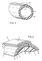
- a tube according to the first variant of the invention explained is shown in cross section and in a schematic perspective illustration in FIG.
- FIG. 2 shows a schematic and semi-perspective illustration and enlarges a detail A from FIG. 1.
- the elements of the jacketed tube shown in FIG. 2 are not shown to scale.
- 1 means the plastic tube, 2 the tube shell in its entirety.
- the structural design of the jacket is not shown in FIG. 1 for the sake of simplifying the drawing, it is shown in FIG. 2, which shows the detail A from FIG. 1 on an enlarged scale.
- the numbers 1 and 2 have the same meaning as in Figure 1. It is 3 the sealable position of the pipe jacket, 4 is the blocking position of the Coat and 5 the protective layer layer of the same.
- 6 is the overlap zone of the jacket, 7 the outside of the jacket, 8 the interface between jacket and plastic tube 1, in the area in which jacket and tube are connected by sealing, 9 is the interface (overlap zone) in overlap part 6 of the jacket; in the area of the boundary surface 9 of the overlap part, the overlapping jacket parts are connected to one another by sealing.
Landscapes
- Engineering & Computer Science (AREA)
- General Engineering & Computer Science (AREA)
- Mechanical Engineering (AREA)
- Physics & Mathematics (AREA)
- Thermal Sciences (AREA)
- Chemical & Material Sciences (AREA)
- Combustion & Propulsion (AREA)
- Laminated Bodies (AREA)
- Rigid Pipes And Flexible Pipes (AREA)
- Pharmaceuticals Containing Other Organic And Inorganic Compounds (AREA)
- Wrappers (AREA)
- Steam Or Hot-Water Central Heating Systems (AREA)
- Harvester Elements (AREA)
- Blow-Moulding Or Thermoforming Of Plastics Or The Like (AREA)
- Fertilizers (AREA)
- Pretreatment Of Seeds And Plants (AREA)
Description
- Die Erfindung betrifft ein Kunststoffrohr mit einem mehrlagigen Mantel, der eine dehnfähige, für Sauerstoff praktisch undurchlässige Sperrlage umfaßt.
- Das erfindungsgemäß ummantelte Kunststoffrohr findet insbesondere im Heizungssektor für Fußboden-Warmwasserheizungen Anwendung. Neben Rohren aus Stahl oder Kupfer haben in den letzten Jahren Kunststoffrohre, insbesondere Rohre aus Polyolefinen, Bedeutung im Heizungsbau erlangt.
- Kunststoffrohre haben jedoch den Nachteil, daß ihre Wandungen bereits bei Raumtemperatur eine unerwünscht hohe Durchlässigkeit für Sauerstoff besitzen. Die Sauerstoffdurchlässigkeit von Rohren, die beispielsweise aus Polyethylen hoher Dichte bestehen und eine Wandstärke von beispielsweise 2 mm haben, beträgt bei 23 °C ca. 3 cm3/m Rohrlänge x Tag x bar. Das Rohr hat einen Außendurchmesser von 20 mm.
- Über das in den Rohren des Heizsystems zirkulierende Heizwasser als Wärmeträger gelangt daher ständig Sauerstoff in den Heizkreislauf und damit in Kontakt mit Eisenteilen des Heizungssystems, beispielsweise dem Heizkessel oder Radiatoren. Die im Heizkreislauf befindlichen Eisenteile unterliegen daher der Korrosion ; es besteht die Gefahr, daß sie nach einigen Jahren des Gebrauchs durch Korrosion unbrauchbar werden.
- Um den genannten Nachteil von Kunststoffrohren zu beseitigen, ist vorgeschlagen worden, die in Heizsystemen verwendeten Rohre aus Kunststoff mit einem Mantel zu umgeben, der aus einem Folienlaminat besteht, das aus einer Schicht aus streckorientierter Polyesterfolie als Trägermaterial, Folie aus Aluminium als sauerstoffundurchlässige Sperrlage und einer Schicht aus Heißkleber besteht.
- Die Polyesterfolie bildet die Außenseite des Mantels, die Kleberschicht grenzt an die Oberfläche des Rohres an und ist mit dieser durch Verklebung verbunden.
- Die bekannte Mantelhülle hat jedoch den Nachteil, daß ihre Aluminiumschicht nach Dehnbeanspruchung beim Biegen des Rohres sowie durch Wärmeausdehnung desselben nicht mehr hinreichend sauerstoffundurchlässig ist, da sie dabei rissig wird. Bei der Wärmeausdehnung des Rohres wirkt sich aus, daß der Wärmeausdehnungskoeffizient des das Rohr bildenden Kunststoffs wesentlich größer ist als der Wärmeausdehnungskoeffizient der mit dem Rohr verbundenen Sperrlage aus Aluminium.
- Die ummantelten Rohre werden teilweise gebogen, um sie in gekrümmten Zustand überzuführen. Dabei wird der das Rohr umgebende Mantel insbesondere dann, wenn die gebogene Rohrkrümmung einen kleinen Radius hat, stark auf Dehnung beansprucht. Nach der Verlegung der ummantelten Rohre wird die Sperrlage des Mantels dadurch auf Dehnung beansprucht, daß sich der Rohrdurchmesser vergrößert, wenn das Rohr heißes Wasser führt. Die Sperrschicht aus Aluminiumfolie ist dann nicht mehr undurchlässig für Sauerstoff.
- In der GB-A-1 171 122 werden ebenfalls Plastikrohre beschrieben, die mit einer Metallfolie überzogen sind. Sie dienen dem Zweck, elektrische Kabel vor Korrosion durch Feuchtigkeit zu schützen. Auch die in dieser Druckschrift beschriebenen Rohre verlieren aus den im Vorstehenden erläuterten Gründen bei häufiger Erwärmung ihre Sperreigenschaften.
- Der Erfindung liegt daher die Aufgabe zugrunde, Kunststoffrohre mit einem Mantel vorzuschlagen, der eine dehnfähige, für Sauerstoff praktisch undurchlässige Sperrlage umfaßt.
- Die der Erfindung zugrundeliegende Aufgabe wird gelöst durch ein ummanteltes Rohr der in Anspruch 1 angegebenen Ausbildung.
- Besondere Ausgestaltungen des erfindungsgemäßen Rohres nach Anspruch 1 sind in den auf diesen rückbezogenen Unteransprüchen konkretisiert.
- Ein gegen Gasdiffusion geschütztes Rohr aus Plastikmaterial ist bereits in der EP-A-30091 (Stand der Technik gemäß Artikel 54 (3) EPÜ) vorgeschlagen worden, die es sich zur Aufgabe gemacht hat, ein flexibles und gasdichtes Rohr zur Verwendung als Heizungsrohr zu schaffen, welches coextrudierbar ist. Das in dieser Druckschrift beschriebene Rohr umfaßt ein inneres, wasserdichtes Plastikmaterial und eine äußere gegen mechanische Beschädigung resistente Schicht, wobei zwischen beiden eine Zwischenschicht angeordnet ist, die gegen Gasdiffusion resistent ist und die sowohl mit der inneren als auch mit der äußeren Schicht verbunden ist. Die gegen Gasdiffusion resistente Schicht besteht nach der Lehre dieser Druckschrift aus Polyvinylalkohol, Polyacrylnitril oder Polyvinylidenchlorid. Demgegenüber umfaßt die vorliegende Erfindung neben der Sperrlage für Sauerstoff aus teilweise in der genannten Druckschrift bereits erwähnten Materialien auch noch eine siegelfähige Schicht, die an den Rohrumfang angrenzt und mit diesem durch Versiegelung verbunden ist.
- Unter einer dehnfähigen, für Sauerstoff praktisch undurchlässigen Sperrlage des Mantels ist definitionsgemäß eine solche zu verstehen, die aus Kunststoff besteht und bei Raumtemperatur mindestens 40 %, vorteilhaft mehr als 100 % dehnbar sowie auch im gedehnten Zustand praktisch undurchlässig für Sauerstoff ist.
- Die Sperrlage hat eine Dicke von wenigstens 5 11m, bevorzugt hat sie eine Dicke im Bereich von 12 bis 25 11m.
- Die Sperrlage besitzt einen Permeationswert für Sauerstoff, der nicht mehr als 5 cm3/m x Tag x bar bei 23 °C und einer relativen Luftfeuchte von 25 % beträgt. Ein ummanteltes Rohr mit einem Durchmesser von 20 mm, dessen Sperrlage durch den angegebenen Permeationswert für Sauerstoff charakterisiert ist, hat eine Sauerstoffdurchlässigkeit von nicht mehr als 0,3 cm3/m Rohrlänge x Tag x bar.
- Die Sperrlage besteht aus synthetischem thermoplastischem Kunststoff, ausgewählt aus einer Gruppe, umfassend Polyvinylalkohol sowie Vinylalkohol-Ethylen-Copolymerisate, die zu mengenmäßig geringem Anteil aus copoiymerisiertem Ethylen bestehen ; vorteilhaft besitzt das Copolymerisat einen Anteil an copolymerisiertem Ethylen von höchstens 40 Mol-%, insbesondere bevorzugt nicht mehr als 20 Mol-%, bezogen auf das Gesamtgewicht des Copolymerisats.
- Unter Vinylalkohol-Ethylen-Copolymerisaten sind definitionsgemäß solche zu verstehen, die durch Copolymerisation von Ethylen mit Vinylacetat und nachfolgender praktisch vollständiger Verseifung des copolymerisierten Vinylacetats derart entstehen, daß wenigstens 97 Gew.-% der Acetylgruppen des Copolymerisats durch Verseifung in OH-Gruppen umgewandelt sind.
- Unter einer Sperrlage aus Polyvinylalkohol ist ein solches Polymerisat zu verstehen, das durch Polymerisation von Vinylacetat und nachfolgender praktisch völliger Verseifung desselben derart entsteht, daß wenigstens 97 Gew.-% Acetatgruppen durch Verseifung in OH-Gruppen umgewandelt sind.
- Die Sperrlage kann auch aus Polyacrylnitril bestehen.
- Die Sperrlage besteht vorteihaft aus Kunststoffolie, insbesondere aus biaxial streckorientierter Kunststoffolie mit den bezeichneten Eigenschaften.
- Die zweite, unmittelbar an die Umfangsfläche des Rohres angrenzende Lage des Mantels besteht aus synthetischem Polymerisat, das durch Wärmeeinwirkung in siegelfähigen Zustand überführbar ist, beispielsweise aus Polyolefin, bevorzugt aus Polyethylen.
- Nach Wiederabkühlung des siegelfähigen Werkstoffs ist dieser befähigt, einen festen Siegelverbund zu bilden. Die Dicke der unmittelbar an die Rohrumfangsfläche angrenzenden siegelfähigen Mantellage beträgt bevorzugt 20 bis 50 wm.
- Die zweite Mantellage ist mit der Umfangsfläche des Rohres durch Siegelung fest verbunden.
- Das ummantelte Rohr kann vorteilhaft derart ausgebildet sein, daß auf der Außenseite der Sperrlage des Mantels eine als Schutzschicht gegen mechanische und/oder chemische Einwirkung dienende, aus zäh-elastischem, thermoplastischem Kunststoff bestehende Lage angeordnet ist; diese kann beipsielsweise aus Polyolefin, bevorzugt Polyethylen, bestehen und beispielsweise eine Dicke von 50 fJ.m besitzen.
- Bei der angegebenen Ausbildung des Mantels befindet sich zwischen der Schutzschicht und der Sperrlage des Mantels eine dünne Schicht aus chemischem Stoff, der infolge seines chemischen Aufbaus befähigt ist, feste Klebeverbindung zwischen der Schutzschicht und der Sperrlage herzustellen, beispielsweise eine Schicht aus Zweikomponentenkleber auf Polyurethanbasis. Die haftvermittelnde Schicht hat eine Dicke, die im Vergleich zur Dicke der Sperrlage bzw. der Schutzschicht vernachlässigbar gering ist.
- Der das Rohr umgebende Mantel ist in Form und Abmessung seines Querschnitts der Form und Abmessung des Rohres angepaßt, das er umhüllt; der Mantel liegt mit seiner Innenseite der Außenseite des Rohres unmittelbar an.
- Das ummantelte Rohr kann auch in der Weise ausgebildet sein, daß auf der Innenseite der durchsichtigen Schutzschicht des Mantels eine Metallschicht aufgedampft ist.
- Gemäß einer ersten Erfindungsvariante besteht der Rohrmantel aus einem Hohlzylinderkörper, der aus einem rechteckigen Folienlaminatzuschnitt gebildet ist. Der Hohlzylinderkörper besitzt einen geraden längsaxialen Schlitz in Form einer längsaxialen Zone, im Bereich welcher Seitenrandbereiche des den Hohlkörper bildenden Folienzuschnitts überlappen, wobei die Ränder der überlappenden Seitenrandbereiche parallel und im Abstand zueinander verlaufen. Der den Hohlkörper bildende Folienlaminatzuschnitt bzw. die durch ihn gebildete Hohlkörperwandung ist beispielsweise wie folgt dreilagig aufgebaut: Er bzw. die Mantelwandung besteht aus einer Lage aus bevorzugt biaxial streckorientierter Folie aus Polyvinylalkohol, Vinylalkohol-Ethylen-Copolymerisat oder Polyacrylnitril, die mit ihrer einen Oberfläche an eine Schutzschichtlage aus Polyolefin, bevorzugt Polyethylen, angrenzt, und mit dieser verbunden ist, während an die andere Oberfläche der bezeichneten Folie eine Lage aus siegelfähigem Werkstoff der angegebenen Art angrenzt und mit dieser verbunden ist. Der wie angegeben ausgebildete Hohlzylinderkörper kann um das Rohr dadurch gebildet werden, daß man einen rechteckigen Folienlaminatzuschnitt des genannten Aufbaus um seine Längsachse als Biegelinie um das Rohr unter Bildung des wie angegeben ausgebildeten Mantel biegt.
- Der aus dem Folienlaminat bestehende Mantel der genannten raumförmlichen Ausbildung umgibt die Rohrumfangsfläche derart, daß die siegelfähige Laminatlage unmittelbar an diese angrenzt und die Schicht des Mantels aus Polyolefin bzw. Polyethylen eine Außenseite bildet. Mantel und Rohrumfangsfläche sind im Grenzflächenbereich durch Versiegelung vollflächig oder in bestimmten Abständen miteinander verbunden.
- Im Überlappungsbereich des Mantels sind die Mantelteile im Grenzflächenbereich zwischen siegelfähiger Lage und Schutzschichtlage durch Versiegelung miteinander verbunden.
- Zur Herstellung eines wie angegeben ummantelten Rohres bestimmter Länge geht man von einem rechteckigen Folienlaminatzuschnitt des geannten Aufbaus aus, dessen Länge der Länge des zu ummantelnden Rohres angepaßt und dessen Breite größer als der Rohrumfang ist. Der Zuschnitt wird dann derart um seine Längsachse als Biegelinie um das zu ummantelnde Rohr gebogen, daß aus dem Zuschnitt ein Hohlzylinderkörper entsteht, der einen geraden, längsaxialen Schlitz in Form einer langsaxialen Zone besitzt, im Bereich welcher Seitenrandbereiche des den Hohlkörper bildenden Zuschnitts überlappen, wobei dessen Seitenränder parallel und abständig zueinander verlaufen. Die Anordnung des Hohlzylinderkörpers um das Rohr erfolgt dabei in der Weise, daß die siegelfähige Lage des diesen bildenden Folienlaminatzuschnitts der Rohrumfangsfläche zugewandt ist und unmittelbar an diese angrenzt. Die Schutzschicht des den Hohlzylinderkörper bildenden Zuschnitts bildet dann die Mantelaußenseite. Der Mantel wird dann mit Wärme einer Temperatur von beispielsweise 150 °C beaufschlagt, die ausreicht, die siegelfähige Mantellage derart zu aktivieren, daß sie zur Verklebung des Mantels mit dem Rohr führt. Der Mantel wird dann unter leichtem Preßdruck an den Rohrumfang angepreßt und dann auf Raumtemperatur abgekühlt. Nach Abkühlung des Mantels besteht zwischen diesem und dem Rohr feste Siegelverbindung.
- Der Überlappungsbereich des Mantels hat bei Verwendung der beispielhaften Verbundfolie - von außen nach innen betrachtet - folgenden Aufbau :
- Polyolefin-, bevorzugt Polyethylenlage/Lage aus Polyvinylalkohol/siegelfähige Lage/Polyolefin-, bevorzugt Polyethylenlage/Lage aus Polyvinylalkohol/siegelfähige Lage ; letztere grenzt an die Rohrumfangsfläche an.
- Die Siegelverbindung im Überlappungsbereich des Mantels erfolgt in der Grenzfläche zwischen der Polyolefinlage eines Überlappungsteils und der an diese angrenzenden siegelfähigen Lage des anderen Übertappungsteiies.
- In einer zweiten Erfindungsvariante kann das ummantelte Rohr derart ausgebildet sein, daß der Mantel aus einem spiralig überlappend gewickelten Folienstreifen besteht, der dem Rohrumfang unter Wickelspannung anliegt. Der Aufbau des Folienstreifens entspricht beispielsweise dem Aufbau des zur Ausbildung der ersten Erfindungsvariante verwendeten dreilagigen Folienlaminats.
- Das Folienband wird spiralig derart um den gesamten Umfang des Rohres über dessen gesamte Länge gewickelt, daß die siegelfähige Schicht des Folienbandes an die Rohrumfangsfläche angrenzt.
- Der gewickelte, durch Wickelspannung an die Rohroberfläche angepreßte Mantel wird dann mit Wärme und vorteilhaft zusätzlich mit Druck beaufschlagt und danach auf Raumtemperatur abgekühlt.
- In einer dritten Erfindungsvariante ist die Sperrlage nahtlos ausgebildet und besteht beispielsweise aus extrudierbarem Polyvinylalkohol. Die dritte Erfindungsvariante ist dadurch herstellbar, daß man auf die Umfangsfläche des zu ummantelnden Kunststoffrohres zunächst Haftvermittler, beispielsweise solchen auf Basis von Ethylen-Copolymerisat mit überwiegendem Anteil an copolymerisiertem Ethylen, aufbringt und danach auf dem wie angegeben vorbehandelten Kunststoffrohr eine Sperrlage aufbringt, die beispielsweise aus Polyvinylalkohol besteht. Die Ummantelung des Rohres mit Polyvinylalkohol erfolgt in bekannter Weise durch ein Extrusionsverfahren mittels hierfür bekannter Vorrichtungen, wobei ein nahtloser Überzug aus Polyvinylalkohol auf dem Rohr entsteht.
- Gegebenenfalls wird auf der Außenseite des nahtlosen Überzugs aus Polyvinylalkohol eine dünne Schicht aus haftvermittelnder chemischer Substanz, beispielsweise Ethylen-Copolymerisat mit überwiegendem Anteil an copolymerisiertem Ethylen, aufgebracht und danach auf diese eine nahtlose Schutzschicht, beispielsweise aus Polyolefin, bevorzugt aus Polyethylen. Die nahtlose Schutzschicht kann beispielsweise mittels eines Extrusionsverfahrens in bekannter Weise und mit hierfür bekannten Vorrichtungen aufgebracht werden, es ist auch möglich, alle genannten Schichten mittels eines Coextrusionsverfahrens zugleich aufzubringen. Geeignete Coextrusionsvorrichtungen sind bekannt.
- Ein aus vernetztem Polyethylen bestehendes Kunststoffrohr mit einem Außendurchmesser von 20 mm und einer Wanddicke von 2 mm hat bei 50 °C eine Sauerstoffdurchlässigkeit von 7,5 cm3/m Rohrlänge x Tag x bar. Ein derartiges Kunststoffrohr hat, wenn es erfindungsgemäß von einem Mantel umgeben ist, der eine beispielsweise 12 µm dicke Sperrlage aus biaxial streckorientierter Polyvinylalkoholfolie umfaßt, eine Durchlässigkeit für Sauerstoff von 0,003 cm3/m Rohrlänge x Tag x bar. Im letztgenannten Fall ist unter Sauerstoffdurchlässigkeit diejenige Menge Sauerstoff zu verstehen, die unter den genannten Bedingungen durch die Ummantelung und die Rohrwand in den Rohrhohlraum einzudringen vermag.
- Die Messungen wurden jeweils bei einer relativen Feuchte von 25 % unter sonst vergleichbaren Versuchsbedingungen durchgeführt.
- Zur Herstellung von erfindungsgemäßen Rohren mit nahtlosem Mantel kann man auch gelangen, indem man Rohr und Mantel durch Coextrusion zugleich bildet.
- Die zwei Figuren umfassende Zeichnung soll die Erfindung beispielhaft erläutern.
- In der Figur 1 ist im Querschnitt und in schematischer perspektivischer Darstellung ein Rohr gemäß der erläuterten ersten Erfindungsvariante dargestellt.
- Figur 2 zeigt in schematischer und halb perspektivischer Darstellung und vergrößert einen Ausschnitt A aus Figur 1. Die Elemente des in Figur 2 gezeigten ummantelten Rohres sind nicht maßstäblich dargestellt.
- In der Figur 1 bedeutet 1 das Kunststoffrohr, 2 den Rohrmantel in seiner Gesamtheit. Die bauliche Ausbildung des Mantels ist in Figur 1 aus Gründen zeichnerischer Vereinfachung nicht dargestellt, sie wird in Figur 2 gezeigt, wobei diese den Ausschnitt A aus Figur 1 vergrößert dargestellt wiedergibt.
- In der Figur 2 haben die Ziffern 1 und 2 dieselbe Bedeutung wie in Figur 1. Es ist 3 die siegelfähige Lage des Rohrmantels, 4 ist die Sperrlage des Mantels und 5 die Schutzschichtlage desselben. 6 ist die Überlappungszone des Mantels, 7 die Mantelaußenseite, 8 die Grenzfläche zwischen Mantel und Kunststoffrohr 1, im Bereich welcher Mantel und Rohr durch Versiegelung miteinander verbunden sind, 9 ist die Grenzfläche (Überlappungszone) im Überlappungsteil 6 des Mantels ; im Bereich der Genzfläche 9 des Überlappungsteils sind die sich überlappenden Mantelteile durch Versiegelung miteinander verbunden.
Claims (8)
Priority Applications (1)
| Application Number | Priority Date | Filing Date | Title |
|---|---|---|---|
| AT81109828T ATE12977T1 (de) | 1980-12-15 | 1981-11-23 | Kunststoffrohr mit sauerstoffdichter ummantelung. |
Applications Claiming Priority (2)
| Application Number | Priority Date | Filing Date | Title |
|---|---|---|---|
| DE3047181 | 1980-12-15 | ||
| DE19803047181 DE3047181A1 (de) | 1980-12-15 | 1980-12-15 | Kunststoffrohr mit sauerstoffdichter ummantelung |
Publications (3)
| Publication Number | Publication Date |
|---|---|
| EP0054751A1 EP0054751A1 (de) | 1982-06-30 |
| EP0054751B1 true EP0054751B1 (de) | 1985-04-24 |
| EP0054751B2 EP0054751B2 (de) | 1990-10-03 |
Family
ID=6119184
Family Applications (1)
| Application Number | Title | Priority Date | Filing Date |
|---|---|---|---|
| EP81109828A Expired - Lifetime EP0054751B2 (de) | 1980-12-15 | 1981-11-23 | Heizungsrohr aus Kunststoff für Fussbodenheizungen mit sauerstoffdichter Ummantelung |
Country Status (9)
| Country | Link |
|---|---|
| US (1) | US4593853A (de) |
| EP (1) | EP0054751B2 (de) |
| JP (1) | JPS57125046A (de) |
| AT (1) | ATE12977T1 (de) |
| CA (1) | CA1173376A (de) |
| DE (2) | DE3047181A1 (de) |
| DK (1) | DK150293C (de) |
| FI (1) | FI73806C (de) |
| NO (1) | NO161141C (de) |
Cited By (1)
| Publication number | Priority date | Publication date | Assignee | Title |
|---|---|---|---|---|
| DE3820254A1 (de) * | 1988-04-22 | 1989-11-09 | Stramax Ag | Kunststoffrohr |
Families Citing this family (22)
| Publication number | Priority date | Publication date | Assignee | Title |
|---|---|---|---|---|
| JPS6183035A (ja) * | 1984-09-06 | 1986-04-26 | 株式会社クラレ | パイプ |
| US4710413A (en) * | 1984-09-24 | 1987-12-01 | Dow Chemical Handels-Und Vertriebsgesellschaft Mbh | Coating composition and its use for the preparation of oxygen barrier coatings on plastic articles |
| DE3929325A1 (de) * | 1989-09-04 | 1991-03-07 | Wirsbo Pex Gmbh | Doppelwandiges leitungsrohr |
| US5284204A (en) * | 1991-05-10 | 1994-02-08 | Electric Power Research Institute, Inc. | Hydronic thermal distribution system for space heating and cooling |
| DE4122119A1 (de) * | 1991-07-04 | 1993-01-07 | Hoechst Ag | Mehrschichtige sauerstoffbarrierefolie, diese enthaltende kunststoffrohre und verwendung derselben |
| FI933877L (fi) * | 1993-09-06 | 1995-03-07 | Neste Oy | Luja kestomuovipohjainen komposiittiputki |
| DE69433017D1 (de) * | 1994-01-26 | 2003-09-11 | Osaka Oxygen Ind | Sauerstoff-Analysator |
| FR2716522B3 (fr) * | 1994-02-22 | 1996-01-12 | Mr Ind | Conduit composite formable à froid et conduit formé à mémoire de forme. |
| DE29710258U1 (de) * | 1997-06-12 | 1997-08-07 | BRUGG Rohrsysteme GmbH, 31515 Wunstorf | Leitungsrohr für den Transport flüssiger oder gasförmiger Medien |
| SE511766C2 (sv) † | 1998-03-23 | 1999-11-22 | Wirsbo Bruks Ab | Flerskiktsrör av plast och dess användning |
| SE513735C2 (sv) * | 1998-05-06 | 2000-10-30 | Wirsbo Bruks Ab | Mediarör av plast, rörsystem, användning av en flytande kristallpolymer i mediarör samt användning av ett dylikt mediarör för ledning av varmvatten |
| EP1118566A1 (de) * | 2000-01-20 | 2001-07-25 | KAVANAGH, Conor | Verfahren zur Produktion und Überwachung von übereinanderliegenden Bahnen mit variablen Daten |
| US20040154676A1 (en) * | 2003-02-06 | 2004-08-12 | Piranha Hose Products, Inc. | Abrasion-resistant hose |
| DE602004016182D1 (de) * | 2003-09-19 | 2008-10-09 | Nkt Flexibles Is | Flexibles, nicht verbundenes rohr und verfahren zur herstellung solch eines rohrs |
| US7308911B2 (en) * | 2004-08-26 | 2007-12-18 | Kuriyama Of American, Inc. | Electronically detectable high-pressure hose and method of determining the location of the hose |
| JP2008008486A (ja) * | 2006-05-31 | 2008-01-17 | Tokai Rubber Ind Ltd | 冷媒輸送用ホース |
| DE102007049330A1 (de) * | 2006-10-12 | 2008-05-21 | Tokai Rubber Industries, Ltd., Komaki | Kältemittel-Transportschlauch |
| US7857010B1 (en) * | 2006-12-22 | 2010-12-28 | Parker-Hannifin Corporation | Low permeability hose system |
| DE102009030632C5 (de) * | 2009-06-25 | 2014-12-31 | Benteler Automobiltechnik Gmbh | Verfahren und Vorrichtung zur Herstellung eines Katalysators |
| US8814333B1 (en) | 2013-03-18 | 2014-08-26 | Xerox Corporation | Oxygen impermeable umbilicals for ink in a printer |
| JP6410127B2 (ja) * | 2014-03-11 | 2018-10-24 | 住友電気工業株式会社 | 電解液循環型電池、熱交換器、及び配管 |
| JP7186103B2 (ja) * | 2019-01-30 | 2022-12-08 | 日立Geニュークリア・エナジー株式会社 | 高密度ポリエチレン管及び継手 |
Family Cites Families (18)
| Publication number | Priority date | Publication date | Assignee | Title |
|---|---|---|---|---|
| US2081538A (en) * | 1934-06-26 | 1937-05-25 | Celluloid Corp | Decorative artificial product |
| US2489130A (en) * | 1947-07-17 | 1949-11-22 | Elson M Harter | Radiant heating system |
| NL237521A (de) * | 1958-03-25 | 1900-01-01 | ||
| US3400029A (en) * | 1965-01-22 | 1968-09-03 | Continental Can Co | Method of making spiral wound container bodies |
| US3561493A (en) * | 1965-04-21 | 1971-02-09 | Paul Maillard | Composite tubes and method of manufacturing same |
| GB1175005A (en) * | 1966-02-03 | 1969-12-23 | U M P Venesta Ltd Formerly Nam | Method and apparatus for producing plastics tubing |
| GB1171122A (en) * | 1966-03-21 | 1969-11-19 | Post Office | Improvements in or relating to Tubes. |
| GB1183313A (en) * | 1966-05-13 | 1970-03-04 | Ici Ltd | Manufacture of Laminated Tubing |
| US3589402A (en) * | 1969-02-26 | 1971-06-29 | Westinghouse Electric Corp | Ink feed tubing |
| US3741253A (en) * | 1971-03-30 | 1973-06-26 | Grace W R & Co | Laminates of ethylene vinyl acetate polymers and polymers of vinylidene chloride |
| ES448091A1 (es) * | 1975-05-22 | 1977-07-01 | Grace W R & Co | Procedimiento para mejorar la resistencia a la deslaminacionde un laminado de peliculas estirado. |
| DE2559318C3 (de) * | 1975-12-31 | 1979-11-29 | Naturin-Werk Becker & Co, 6940 Weinheim | Verwendung eines elastischen Polyurethans zum Herstellen einer mindestens einschichtigen, gegebenenfalls biaxial gereckten Wursthülle für Koch- und Brühwürste |
| DK154615C (da) * | 1976-02-18 | 1989-05-22 | Montedison Spa | Fremgangsmaade til fremstilling af hullegemer af to eller flere lag |
| DE2724252C2 (de) * | 1977-05-28 | 1982-12-16 | Hoechst Ag, 6000 Frankfurt | Schlauchförmiges Verpackungsmaterial, vorzugsweise zur Verwendung als Wursthülle |
| US4178401A (en) * | 1978-01-09 | 1979-12-11 | W. R. Grace & Co. | Packaging film comprising a blended self-welding layer |
| DE7927416U1 (de) * | 1979-09-27 | 1980-01-17 | Egeplast Werner Strumann Gmbh & Co, 4407 Emsdetten | Kunststoffrohr |
| CA1145272A (en) * | 1979-11-28 | 1983-04-26 | Jerker Skarelius | Gaseous diffusion resistant article and method utilizing same |
| US4296156A (en) * | 1979-12-26 | 1981-10-20 | Union Carbide Corporation | Multilayer film including a polyurethane |
-
1980
- 1980-12-15 DE DE19803047181 patent/DE3047181A1/de not_active Withdrawn
-
1981
- 1981-11-23 AT AT81109828T patent/ATE12977T1/de active
- 1981-11-23 EP EP81109828A patent/EP0054751B2/de not_active Expired - Lifetime
- 1981-11-23 DE DE8181109828T patent/DE3170191D1/de not_active Expired
- 1981-12-11 FI FI813994A patent/FI73806C/fi not_active IP Right Cessation
- 1981-12-14 CA CA000392249A patent/CA1173376A/en not_active Expired
- 1981-12-14 DK DK552681A patent/DK150293C/da not_active IP Right Cessation
- 1981-12-14 NO NO814262A patent/NO161141C/no unknown
- 1981-12-15 JP JP56201018A patent/JPS57125046A/ja active Granted
-
1983
- 1983-10-11 US US06/540,114 patent/US4593853A/en not_active Expired - Lifetime
Cited By (1)
| Publication number | Priority date | Publication date | Assignee | Title |
|---|---|---|---|---|
| DE3820254A1 (de) * | 1988-04-22 | 1989-11-09 | Stramax Ag | Kunststoffrohr |
Also Published As
| Publication number | Publication date |
|---|---|
| EP0054751A1 (de) | 1982-06-30 |
| FI73806C (fi) | 1987-11-09 |
| DE3047181A1 (de) | 1982-06-16 |
| FI73806B (fi) | 1987-07-31 |
| DK150293C (da) | 1987-10-26 |
| NO161141B (no) | 1989-03-28 |
| FI813994L (fi) | 1982-06-16 |
| EP0054751B2 (de) | 1990-10-03 |
| DE3170191D1 (en) | 1985-05-30 |
| JPS57125046A (en) | 1982-08-04 |
| DK552681A (da) | 1982-06-16 |
| DK150293B (da) | 1987-02-02 |
| NO814262L (no) | 1982-06-16 |
| CA1173376A (en) | 1984-08-28 |
| NO161141C (no) | 1989-07-05 |
| US4593853A (en) | 1986-06-10 |
| JPH0251731B2 (de) | 1990-11-08 |
| ATE12977T1 (de) | 1985-05-15 |
Similar Documents
| Publication | Publication Date | Title |
|---|---|---|
| EP0054751B1 (de) | Heizungsrohr aus Kunststoff für Fussbodenheizungen mit sauerstoffdichter Ummantelung | |
| DE1640177C3 (de) | Fernmeldekabel | |
| DE3782115T2 (de) | Mehrschicht-filmsystem und dieses enthaltendes, elektrisches kabel. | |
| CH444928A (de) | Ummanteltes elektrisches Kabel und Verfahren zu seiner Herstellung | |
| DE1704117B2 (de) | Verfahren zum Herstellen gas- und flüssigkeitsdichter Tuben | |
| EP1471299B1 (de) | Wärmeisoliertes Leitungsrohr | |
| EP0522380A1 (de) | Mehrschichtige Sauerstoffbarrierefolie, diese enthaltende Kunststoffrohre und Verwendung derselben | |
| EP0006422B1 (de) | Verfahren zum Umhüllen gerader Rohrstücke mit Zuschnitten aus Folienlaminat | |
| DE3307120A1 (de) | Fernwaermeleitungsrohr | |
| EP0375608A1 (de) | Flexibles Medientransportrohr | |
| DE202019004158U1 (de) | Isoliertes Rohr | |
| DE2809663A1 (de) | Streifenfoermiges biegsames verkleidungsmaterial zum ummanteln von waerme-, kaelte- und schallisolierungen | |
| AT391749B (de) | Flexibles leitungsrohr zum fortleiten fluessiger oder gasfoermiger medien | |
| DE2338431C2 (de) | Verfahren zur Ummantelung eines länglichen Gegenstandes | |
| EP0282960A2 (de) | Optisches Kabelelement und optisches Kabel | |
| DE2025026A1 (de) | Bahnförmiges Isoliermaterial | |
| DE8033299U1 (de) | Kunststoffrohr mit sauerstoffdichter ummantelung | |
| DE2739321C2 (de) | Verfahren zur Herstellung eines kunststoffbeschichteten Metallrohres für Installationszwecke | |
| DE3444523C2 (de) | ||
| DE3409013A1 (de) | Wasserinstallationsrohr, insbesondere fussbodenheizungsrohr | |
| DE3780904T2 (de) | Waermeschrumpfender artikel. | |
| CH405842A (de) | Harte Kunststoff-Folie zum Ummanteln einer zylindrischen Wärme-, Kälte- oder Schallisolierung | |
| DE3225869A1 (de) | Vorrichtung zur herstellung eines leitungsrohres aus kunststoff | |
| DE8133466U1 (de) | Rohr für Warmwasserfußbodenheizung | |
| DE3531248A1 (de) | Verfahren zur herstellung einer zur direkten kaschierung mit weiteren bahnen oder matten geeigneten schaumstoffbahn oder -matte |
Legal Events
| Date | Code | Title | Description |
|---|---|---|---|
| PUAI | Public reference made under article 153(3) epc to a published international application that has entered the european phase |
Free format text: ORIGINAL CODE: 0009012 |
|
| AK | Designated contracting states |
Designated state(s): AT BE CH DE FR GB NL SE |
|
| 17P | Request for examination filed |
Effective date: 19820702 |
|
| GRAA | (expected) grant |
Free format text: ORIGINAL CODE: 0009210 |
|
| AK | Designated contracting states |
Designated state(s): AT BE CH DE FR GB LI NL SE |
|
| REF | Corresponds to: |
Ref document number: 12977 Country of ref document: AT Date of ref document: 19850515 Kind code of ref document: T |
|
| REF | Corresponds to: |
Ref document number: 3170191 Country of ref document: DE Date of ref document: 19850530 |
|
| ET | Fr: translation filed | ||
| PLBI | Opposition filed |
Free format text: ORIGINAL CODE: 0009260 |
|
| PLBI | Opposition filed |
Free format text: ORIGINAL CODE: 0009260 |
|
| 26 | Opposition filed |
Opponent name: UPONOR AB Effective date: 19860122 |
|
| NLR1 | Nl: opposition has been filed with the epo |
Opponent name: UPONOR AB |
|
| 26 | Opposition filed |
Opponent name: FRAENKISCHE ROHRWERKE GEBR. KIRCHNER GMBH & CO., D Effective date: 19860124 Opponent name: REHAU PLASTIKS AG + CO Effective date: 19860123 |
|
| NLR1 | Nl: opposition has been filed with the epo |
Opponent name: FRAENKISCHE ROHRWERKE GEBR.KIRCHNER GMBH & CO. Opponent name: REHAU PLASTIKS AG |
|
| PLBG | Opposition deemed not to have been filed |
Free format text: ORIGINAL CODE: 0009274 |
|
| NLXE | Nl: other communications concerning ep-patents (part 3 heading xe) |
Free format text: IN PAT.BUL.07/86,PAGE 821:OPPOSITION I SHOULD BE DEEMED NOT TO HAVE BEEN FILED |
|
| 26D | Opposition deemed not to have been filed |
Opponent name: REHAU PLASTIKS AG + CO Effective date: 19870216 |
|
| RTI2 | Title (correction) | ||
| PUAH | Patent maintained in amended form |
Free format text: ORIGINAL CODE: 0009272 |
|
| STAA | Information on the status of an ep patent application or granted ep patent |
Free format text: STATUS: PATENT MAINTAINED AS AMENDED |
|
| 27A | Patent maintained in amended form |
Effective date: 19901003 |
|
| AK | Designated contracting states |
Kind code of ref document: B2 Designated state(s): AT BE CH DE FR GB LI NL SE |
|
| ET3 | Fr: translation filed ** decision concerning opposition | ||
| NLR2 | Nl: decision of opposition | ||
| NLR3 | Nl: receipt of modified translations in the netherlands language after an opposition procedure | ||
| REG | Reference to a national code |
Ref country code: CH Ref legal event code: PUE Owner name: WOLFF WALSRODE AKTIENGESELLSCHAFT |
|
| REG | Reference to a national code |
Ref country code: GB Ref legal event code: 732E |
|
| REG | Reference to a national code |
Ref country code: FR Ref legal event code: TP |
|
| NLS | Nl: assignments of ep-patents |
Owner name: WOLFF WALSRODE AKTIENGESELLSCHAFT TE WALSRODE, BON |
|
| EAL | Se: european patent in force in sweden |
Ref document number: 81109828.4 |
|
| PGFP | Annual fee paid to national office [announced via postgrant information from national office to epo] |
Ref country code: DE Payment date: 19961014 Year of fee payment: 16 |
|
| PGFP | Annual fee paid to national office [announced via postgrant information from national office to epo] |
Ref country code: SE Payment date: 19961015 Year of fee payment: 16 |
|
| PGFP | Annual fee paid to national office [announced via postgrant information from national office to epo] |
Ref country code: CH Payment date: 19961021 Year of fee payment: 16 |
|
| PGFP | Annual fee paid to national office [announced via postgrant information from national office to epo] |
Ref country code: FR Payment date: 19961030 Year of fee payment: 16 |
|
| PGFP | Annual fee paid to national office [announced via postgrant information from national office to epo] |
Ref country code: AT Payment date: 19961112 Year of fee payment: 16 |
|
| PGFP | Annual fee paid to national office [announced via postgrant information from national office to epo] |
Ref country code: GB Payment date: 19961114 Year of fee payment: 16 |
|
| PGFP | Annual fee paid to national office [announced via postgrant information from national office to epo] |
Ref country code: BE Payment date: 19961128 Year of fee payment: 16 |
|
| PGFP | Annual fee paid to national office [announced via postgrant information from national office to epo] |
Ref country code: NL Payment date: 19961129 Year of fee payment: 16 |
|
| PG25 | Lapsed in a contracting state [announced via postgrant information from national office to epo] |
Ref country code: GB Free format text: LAPSE BECAUSE OF NON-PAYMENT OF DUE FEES Effective date: 19971123 Ref country code: AT Free format text: LAPSE BECAUSE OF NON-PAYMENT OF DUE FEES Effective date: 19971123 |
|
| PG25 | Lapsed in a contracting state [announced via postgrant information from national office to epo] |
Ref country code: SE Free format text: LAPSE BECAUSE OF NON-PAYMENT OF DUE FEES Effective date: 19971124 |
|
| PG25 | Lapsed in a contracting state [announced via postgrant information from national office to epo] |
Ref country code: LI Free format text: LAPSE BECAUSE OF NON-PAYMENT OF DUE FEES Effective date: 19971130 Ref country code: FR Free format text: THE PATENT HAS BEEN ANNULLED BY A DECISION OF A NATIONAL AUTHORITY Effective date: 19971130 Ref country code: CH Free format text: LAPSE BECAUSE OF NON-PAYMENT OF DUE FEES Effective date: 19971130 Ref country code: BE Free format text: LAPSE BECAUSE OF NON-PAYMENT OF DUE FEES Effective date: 19971130 |
|
| BERE | Be: lapsed |
Owner name: WOLFF WALSRODE A.G. Effective date: 19971130 |
|
| PG25 | Lapsed in a contracting state [announced via postgrant information from national office to epo] |
Ref country code: NL Free format text: LAPSE BECAUSE OF NON-PAYMENT OF DUE FEES Effective date: 19980601 |
|
| GBPC | Gb: european patent ceased through non-payment of renewal fee |
Effective date: 19971123 |
|
| REG | Reference to a national code |
Ref country code: CH Ref legal event code: PL |
|
| PG25 | Lapsed in a contracting state [announced via postgrant information from national office to epo] |
Ref country code: DE Free format text: LAPSE BECAUSE OF NON-PAYMENT OF DUE FEES Effective date: 19980801 |
|
| EUG | Se: european patent has lapsed |
Ref document number: 81109828.4 |
|
| NLV4 | Nl: lapsed or anulled due to non-payment of the annual fee |
Effective date: 19980601 |
|
| REG | Reference to a national code |
Ref country code: FR Ref legal event code: ST |
|
| PLAB | Opposition data, opponent's data or that of the opponent's representative modified |
Free format text: ORIGINAL CODE: 0009299OPPO |