EP0054252A1 - Dispositif pour fendre le bois - Google Patents
Dispositif pour fendre le bois Download PDFInfo
- Publication number
- EP0054252A1 EP0054252A1 EP81110272A EP81110272A EP0054252A1 EP 0054252 A1 EP0054252 A1 EP 0054252A1 EP 81110272 A EP81110272 A EP 81110272A EP 81110272 A EP81110272 A EP 81110272A EP 0054252 A1 EP0054252 A1 EP 0054252A1
- Authority
- EP
- European Patent Office
- Prior art keywords
- split
- cutting
- iron
- irons
- bar
- Prior art date
- Legal status (The legal status is an assumption and is not a legal conclusion. Google has not performed a legal analysis and makes no representation as to the accuracy of the status listed.)
- Granted
Links
Images

Classifications
-
- B—PERFORMING OPERATIONS; TRANSPORTING
- B27—WORKING OR PRESERVING WOOD OR SIMILAR MATERIAL; NAILING OR STAPLING MACHINES IN GENERAL
- B27L—REMOVING BARK OR VESTIGES OF BRANCHES; SPLITTING WOOD; MANUFACTURE OF VENEER, WOODEN STICKS, WOOD SHAVINGS, WOOD FIBRES OR WOOD POWDER
- B27L7/00—Arrangements for splitting wood
- B27L7/06—Arrangements for splitting wood using wedges, knives or spreaders
Definitions
- a device with two pairs of splitting irons, by means of which a block of wood can be split into four essentially identical parts, is known for example from SE-PS 222 393.
- the known devices are only suitable for splitting blocks of wood with a relatively small diameter, which are split into two or three sufficiently small logs by means of these devices, which are suitable for burning in wood stoves or open fireplaces.
- the invention has for its object to improve a device of the aforementioned type so that even larger diameter wooden blocks can be split into logs of the size required for fireplaces of the aforementioned type in a single pass through the device.
- the advantage of this device is, in particular, that not only does a large number of logs be obtained when the Rammbär collapses, but also that the Rammbär's force is fully exploited by the fact that in the lower levels, in which due to the previous division of the A smaller splitting force is required, the length of the cutting edges is a greater overall.
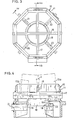
- the splitting device 10 shown in FIGS. 3 and 4 consists of an octagonal frame 11 which is attached to the stand 12 shown in FIGS. 1 and 2.
- the wooden block 13 lies on the splitting device 10 below the hydraulically operated ramming bear 14.
- the ramming bear has two grooves 15 arranged perpendicular to one another, which divide the lower end face of the ramming bear into four abutting surfaces 15a, which are between the two can penetrate the upper split iron.
- the cutting edges of the splitting irons are parallel to each other, to the movement direction of the ramming vertical planes.
- the uppermost split iron 16 extends diametrically in the octagonal frame 11, on the opposite side parts of which the ends of the split iron 16 are detachably arranged in recesses.
- the next lower equally long split bar 17 is arranged at right angles to the split bar 16.
- the outer ends of these split bars located in a fourth plane reach through recesses provided in the side parts of the frame 11, as can be seen from FIG. 4.
- the block of wood can be held on the splitting device by any means not shown in the drawing. These can consist, for example, of grippers that release it at the moment the ramming bear hits. At the top of the splitting device there can also be horizontal tabs which can be lowered against the restoring force of springs, which keep the wooden block at a distance from the uppermost splitting iron and only lower when the ramming bear hits the wooden block.
- the splitting of the block of wood begins with the impact of the block of wood on the first splitting iron 16, so that it is split into two parts when its lower end face strikes the second splitting iron 17 (FIG. 6).
- the two halves of the block are split a total of four parts, which essentially have the shape of a quadrant.
- these parts are pushed radially outwards, as shown in FIG. 7.
- each of these parts is split into a sector-shaped inner log and an outer curved log.
- the four inner logs fall freely through the ring of the split bar 18, while the outer logs each hit one of the split bars 20, 21, 22, 23 and are split into two smaller logs by means of this.
- the cutting edges of the splitting irons have a certain cutting angle, so that when splitting the wooden block the risk is avoided as far as possible that the cutting edges penetrate into the wooden block at an angle to the fibrous structure, the cutting edges rather in essentially split the block of wood in the direction of the fiber structure, whereby the splitting forces can be kept low.
- the outer surface 18b of the ring-shaped split bar 18 is formed in its upper cutting area 18b by a relatively narrow conical surface, which merges into a wider, concave-widening annular surface 18c with a radius r, the surface of which adjoins the outer edge surface 18b with the inside surface of the split bar forms, which is smaller than the cutting angle b of the split bar, as shown in FIG. 4.
- the result of this is that the cutting edge has essentially the same direction as the direction of movement of the parts 13a or runs parallel to the gap surfaces thereof when they strike the cutting edge of the annular split bar.
- the gap surfaces created with the cutting edge of this wedge 18 thus run in the direction of the fiber structure.
- the logs 13b thus slide with their lower edges along the concave surface 18c and are thus pushed outwards.
- This design of the split bar 18 facilitates the splitting because sliding friction resistances on the The outer surface of the split bar 18 and the cutting through of the fiber structure can be avoided. The splitting forces occurring here are significantly reduced for these two reasons.
Landscapes
- Life Sciences & Earth Sciences (AREA)
- Engineering & Computer Science (AREA)
- Wood Science & Technology (AREA)
- Forests & Forestry (AREA)
- Preparation Of Compounds By Using Micro-Organisms (AREA)
- Breeding Of Plants And Reproduction By Means Of Culturing (AREA)
- Debarking, Splitting, And Disintegration Of Timber (AREA)
- Shearing Machines (AREA)
- Graft Or Block Polymers (AREA)
- Materials For Medical Uses (AREA)
- Diaphragms For Electromechanical Transducers (AREA)
- Arc Welding In General (AREA)
- Chemical And Physical Treatments For Wood And The Like (AREA)
Priority Applications (1)
| Application Number | Priority Date | Filing Date | Title |
|---|---|---|---|
| AT81110272T ATE9290T1 (de) | 1980-12-12 | 1981-12-09 | Geraet zum spalten von brennholz. |
Applications Claiming Priority (2)
| Application Number | Priority Date | Filing Date | Title |
|---|---|---|---|
| SE8008770A SE422174B (sv) | 1980-12-12 | 1980-12-12 | Vedklyvningsanordning |
| SE8008770 | 1980-12-12 |
Publications (2)
| Publication Number | Publication Date |
|---|---|
| EP0054252A1 true EP0054252A1 (fr) | 1982-06-23 |
| EP0054252B1 EP0054252B1 (fr) | 1984-09-12 |
Family
ID=20342464
Family Applications (1)
| Application Number | Title | Priority Date | Filing Date |
|---|---|---|---|
| EP81110272A Expired EP0054252B1 (fr) | 1980-12-12 | 1981-12-09 | Dispositif pour fendre le bois |
Country Status (8)
| Country | Link |
|---|---|
| US (1) | US4434825A (fr) |
| EP (1) | EP0054252B1 (fr) |
| AT (1) | ATE9290T1 (fr) |
| CA (1) | CA1174570A (fr) |
| DE (1) | DE3166090D1 (fr) |
| FI (1) | FI813966L (fr) |
| NO (1) | NO151112C (fr) |
| SE (1) | SE422174B (fr) |
Cited By (5)
| Publication number | Priority date | Publication date | Assignee | Title |
|---|---|---|---|---|
| US4782866A (en) * | 1988-01-19 | 1988-11-08 | Charlie Valdez | Log splitting head |
| AT401750B (de) * | 1995-03-29 | 1996-11-25 | Hechenblaickner Josef | Vorrichtung zum spalten von holzrohlingen |
| US5791389A (en) * | 1997-03-28 | 1998-08-11 | Yvonne Company | Apparatus and method for forming firewood logs |
| AT514488A3 (de) * | 2013-06-21 | 2015-12-15 | Binderberger Maschb Gmbh | Spaltmesservorrichtung |
| FR3105060A1 (fr) * | 2019-12-23 | 2021-06-25 | Home Clotures D'aquitaine | Bloc de decoupe pour rondins de bois et installation comprenant un tel bloc |
Families Citing this family (9)
| Publication number | Priority date | Publication date | Assignee | Title |
|---|---|---|---|---|
| US4800937A (en) * | 1988-01-14 | 1989-01-31 | Mangus Sr Kenneth H | Log splitting apparatus |
| US4830071A (en) * | 1988-03-22 | 1989-05-16 | Gollahon Robert J | Wood processing machine |
| US6609545B1 (en) * | 2001-06-15 | 2003-08-26 | Ian Van Gelder | Wood cutting head structure |
| ITTV20070159A1 (it) * | 2007-09-20 | 2009-03-21 | Tollot Raffaelo Snc Off | Macchina spaccalegna con dispositivo di centraggio dell'elemento da spaccare rispetto alla testata stessa e sistema di espulsione a testa di trafila. |
| US20110036455A1 (en) * | 2009-08-14 | 2011-02-17 | Charlie Valdez | Log splitter |
| US9061436B2 (en) | 2010-05-11 | 2015-06-23 | Brent A. Fisher | Staged contact splitting blade assembly |
| AT14246U1 (de) * | 2014-06-18 | 2015-06-15 | Philipp Glöckner | Zündholzvorrichtung für stehende Holzspalter |
| CN107283583B (zh) * | 2017-07-11 | 2020-02-07 | 马正平 | 一种半自动劈柴装置 |
| CN107283582B (zh) * | 2017-07-11 | 2020-02-07 | 林明繁 | 一种自动劈柴装置 |
Citations (9)
| Publication number | Priority date | Publication date | Assignee | Title |
|---|---|---|---|---|
| DE198082C (fr) * | ||||
| CH85257A (de) * | 1919-08-30 | 1920-10-01 | A Eichmann | Maschine zum Spalten von Holzklötzen. |
| US1594599A (en) * | 1923-04-11 | 1926-08-03 | John E Carlson | Machine for cutting reed |
| US1701001A (en) * | 1927-08-25 | 1929-02-05 | Francis H Hampton | Wood-chopping device |
| DE507680C (de) * | 1928-08-26 | 1930-09-19 | G J Killmeyer Holz U Metallwar | Kleinholzspalter mit mehreren kreuzfoermig angeordneten Messern |
| FR723802A (fr) * | 1931-10-02 | 1932-04-15 | Rotin Sa Du | Outil et porte-outil formant déversoir pour machines à fendre le rotin ou analogue |
| SE222393C1 (fr) * | 1964-09-30 | 1968-09-03 | ||
| DE1453349A1 (de) * | 1964-09-30 | 1969-07-31 | Miag Muehlenbau & Ind Gmbh | Spaltmesser fuer Holz-Spaltmaschinen |
| US4294295A (en) * | 1978-09-25 | 1981-10-13 | Bloomfield Farms, Inc. | Apparatus for cutting and splitting firewood |
-
1980
- 1980-12-12 SE SE8008770A patent/SE422174B/sv not_active IP Right Cessation
-
1981
- 1981-12-01 US US06/326,394 patent/US4434825A/en not_active Expired - Fee Related
- 1981-12-09 DE DE8181110272T patent/DE3166090D1/de not_active Expired
- 1981-12-09 EP EP81110272A patent/EP0054252B1/fr not_active Expired
- 1981-12-09 AT AT81110272T patent/ATE9290T1/de active
- 1981-12-10 CA CA000391962A patent/CA1174570A/fr not_active Expired
- 1981-12-10 FI FI813966A patent/FI813966L/fi not_active Application Discontinuation
- 1981-12-11 NO NO814237A patent/NO151112C/no unknown
Patent Citations (9)
| Publication number | Priority date | Publication date | Assignee | Title |
|---|---|---|---|---|
| DE198082C (fr) * | ||||
| CH85257A (de) * | 1919-08-30 | 1920-10-01 | A Eichmann | Maschine zum Spalten von Holzklötzen. |
| US1594599A (en) * | 1923-04-11 | 1926-08-03 | John E Carlson | Machine for cutting reed |
| US1701001A (en) * | 1927-08-25 | 1929-02-05 | Francis H Hampton | Wood-chopping device |
| DE507680C (de) * | 1928-08-26 | 1930-09-19 | G J Killmeyer Holz U Metallwar | Kleinholzspalter mit mehreren kreuzfoermig angeordneten Messern |
| FR723802A (fr) * | 1931-10-02 | 1932-04-15 | Rotin Sa Du | Outil et porte-outil formant déversoir pour machines à fendre le rotin ou analogue |
| SE222393C1 (fr) * | 1964-09-30 | 1968-09-03 | ||
| DE1453349A1 (de) * | 1964-09-30 | 1969-07-31 | Miag Muehlenbau & Ind Gmbh | Spaltmesser fuer Holz-Spaltmaschinen |
| US4294295A (en) * | 1978-09-25 | 1981-10-13 | Bloomfield Farms, Inc. | Apparatus for cutting and splitting firewood |
Cited By (7)
| Publication number | Priority date | Publication date | Assignee | Title |
|---|---|---|---|---|
| US4782866A (en) * | 1988-01-19 | 1988-11-08 | Charlie Valdez | Log splitting head |
| AT401750B (de) * | 1995-03-29 | 1996-11-25 | Hechenblaickner Josef | Vorrichtung zum spalten von holzrohlingen |
| US5791389A (en) * | 1997-03-28 | 1998-08-11 | Yvonne Company | Apparatus and method for forming firewood logs |
| AT514488A3 (de) * | 2013-06-21 | 2015-12-15 | Binderberger Maschb Gmbh | Spaltmesservorrichtung |
| AT514488B1 (de) * | 2013-06-21 | 2016-09-15 | Binderberger Maschb Gmbh | Spaltmesservorrichtung |
| FR3105060A1 (fr) * | 2019-12-23 | 2021-06-25 | Home Clotures D'aquitaine | Bloc de decoupe pour rondins de bois et installation comprenant un tel bloc |
| WO2021130436A1 (fr) * | 2019-12-23 | 2021-07-01 | Home Clotures D'aquitaine | Bloc de decoupe pour rondins de bois et installation comprenant un tel bloc |
Also Published As
| Publication number | Publication date |
|---|---|
| NO814237L (no) | 1982-06-14 |
| ATE9290T1 (de) | 1984-09-15 |
| NO151112C (no) | 1985-02-13 |
| US4434825A (en) | 1984-03-06 |
| FI813966L (fi) | 1982-06-13 |
| EP0054252B1 (fr) | 1984-09-12 |
| DE3166090D1 (en) | 1984-10-18 |
| SE422174B (sv) | 1982-02-22 |
| CA1174570A (fr) | 1984-09-18 |
| NO151112B (no) | 1984-11-05 |
Similar Documents
| Publication | Publication Date | Title |
|---|---|---|
| EP0054252B1 (fr) | Dispositif pour fendre le bois | |
| DE2840660C2 (fr) | ||
| DE69018997T2 (de) | Kreissägeblattanordnung. | |
| EP0806130B1 (fr) | Rouleau, en particulier rouleaux de compactage | |
| DE1684042B1 (de) | Vorrichtung zum Zerteilen noch in plastischem Zustand befindlicher Massebloecke,insbesondere Porenbetonbloecke | |
| DE3104315A1 (de) | Vorrichtung zum teilen von knollenfruechten | |
| DE102015114122B3 (de) | Vorrichtung zum Abtragen von Bauwerkstoff | |
| DE2338108A1 (de) | Klumpen-zerkleinerer | |
| EP1050386A1 (fr) | Procédé et dispositif de transformation des bois ronds en planches | |
| DE925136C (de) | Schneidvorrichtung fuer Strohschneidemaschinen | |
| DE19809100A1 (de) | Vorrichtung zum Spalten von scheibenförmigen Holzstücken in Scheithölzer | |
| DE930900C (de) | Aushebe- und Umsetzgeraet fuer Pflanzen, insbesondere fuer Waldpflanzen | |
| DE2811376A1 (de) | Rotir fuer prallmuehlen, insbesondere fuer sandprallmuehlen | |
| DE328258C (de) | Vorrichtung zum Abscheren von Rohren und rohrfoermigen Koerpern mittels profilierterMesser | |
| DE874966C (de) | Bodenbearbeitungsgeraet mit in einem Rahmengestell gelagerter Walze | |
| DE1500653A1 (de) | Schraubverbindung | |
| DE7826717U1 (de) | Hammer fuer hammerbrecher und mit derartigen haemmern ausgeruesteter rotor fuer einen brecher | |
| AT19883B (de) | Riemscheibe veränderbaren Durchmessers. | |
| DE563684C (de) | Selbsttaetig arbeitende Kohlenschraemmaschine | |
| DE888027C (de) | Geraet zum Ausheben und Umsetzen von Pflanzen | |
| DE2707248A1 (de) | Kreiselmaehwerk | |
| DE3725726C1 (en) | Ditching roller on contractors plant - incorporates segments screwed to cutter shaft to form disc | |
| DE428617C (de) | Vorrichtung zum Zerschneiden von Brettern u. dgl. in Holzstaebe von rechteckigem Querschnitt | |
| DE9218843U1 (de) | Absenkvorrichtung für lasttragende Systemteile | |
| DE3222201C2 (de) | Tiefenerder |
Legal Events
| Date | Code | Title | Description |
|---|---|---|---|
| PUAI | Public reference made under article 153(3) epc to a published international application that has entered the european phase |
Free format text: ORIGINAL CODE: 0009012 |
|
| AK | Designated contracting states |
Designated state(s): AT CH DE FR |
|
| RBV | Designated contracting states (corrected) |
Designated state(s): AT CH DE FR LI |
|
| 17P | Request for examination filed |
Effective date: 19821218 |
|
| GRAA | (expected) grant |
Free format text: ORIGINAL CODE: 0009210 |
|
| AK | Designated contracting states |
Designated state(s): AT CH DE FR LI |
|
| PG25 | Lapsed in a contracting state [announced via postgrant information from national office to epo] |
Ref country code: FR Free format text: THE PATENT HAS BEEN ANNULLED BY A DECISION OF A NATIONAL AUTHORITY Effective date: 19840912 |
|
| REF | Corresponds to: |
Ref document number: 9290 Country of ref document: AT Date of ref document: 19840915 Kind code of ref document: T |
|
| REF | Corresponds to: |
Ref document number: 3166090 Country of ref document: DE Date of ref document: 19841018 |
|
| PGFP | Annual fee paid to national office [announced via postgrant information from national office to epo] |
Ref country code: AT Payment date: 19841211 Year of fee payment: 4 |
|
| PGFP | Annual fee paid to national office [announced via postgrant information from national office to epo] |
Ref country code: DE Payment date: 19850107 Year of fee payment: 4 |
|
| PLBE | No opposition filed within time limit |
Free format text: ORIGINAL CODE: 0009261 |
|
| STAA | Information on the status of an ep patent application or granted ep patent |
Free format text: STATUS: NO OPPOSITION FILED WITHIN TIME LIMIT |
|
| EN | Fr: translation not filed | ||
| 26N | No opposition filed | ||
| PG25 | Lapsed in a contracting state [announced via postgrant information from national office to epo] |
Ref country code: AT Effective date: 19851209 |
|
| PG25 | Lapsed in a contracting state [announced via postgrant information from national office to epo] |
Ref country code: LI Effective date: 19851231 Ref country code: CH Effective date: 19851231 |
|
| REG | Reference to a national code |
Ref country code: CH Ref legal event code: PL |
|
| PG25 | Lapsed in a contracting state [announced via postgrant information from national office to epo] |
Ref country code: DE Effective date: 19860902 |