EP0054252A1 - Wood splitting apparatus - Google Patents
Wood splitting apparatus Download PDFInfo
- Publication number
- EP0054252A1 EP0054252A1 EP81110272A EP81110272A EP0054252A1 EP 0054252 A1 EP0054252 A1 EP 0054252A1 EP 81110272 A EP81110272 A EP 81110272A EP 81110272 A EP81110272 A EP 81110272A EP 0054252 A1 EP0054252 A1 EP 0054252A1
- Authority
- EP
- European Patent Office
- Prior art keywords
- split
- cutting
- iron
- irons
- bar
- Prior art date
- Legal status (The legal status is an assumption and is not a legal conclusion. Google has not performed a legal analysis and makes no representation as to the accuracy of the status listed.)
- Granted
Links
Images

Classifications
-
- B—PERFORMING OPERATIONS; TRANSPORTING
- B27—WORKING OR PRESERVING WOOD OR SIMILAR MATERIAL; NAILING OR STAPLING MACHINES IN GENERAL
- B27L—REMOVING BARK OR VESTIGES OF BRANCHES; SPLITTING WOOD; MANUFACTURE OF VENEER, WOODEN STICKS, WOOD SHAVINGS, WOOD FIBRES OR WOOD POWDER
- B27L7/00—Arrangements for splitting wood
- B27L7/06—Arrangements for splitting wood using wedges, knives or spreaders
Definitions
- a device with two pairs of splitting irons, by means of which a block of wood can be split into four essentially identical parts, is known for example from SE-PS 222 393.
- the known devices are only suitable for splitting blocks of wood with a relatively small diameter, which are split into two or three sufficiently small logs by means of these devices, which are suitable for burning in wood stoves or open fireplaces.
- the invention has for its object to improve a device of the aforementioned type so that even larger diameter wooden blocks can be split into logs of the size required for fireplaces of the aforementioned type in a single pass through the device.
- the advantage of this device is, in particular, that not only does a large number of logs be obtained when the Rammbär collapses, but also that the Rammbär's force is fully exploited by the fact that in the lower levels, in which due to the previous division of the A smaller splitting force is required, the length of the cutting edges is a greater overall.
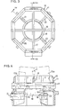
- the splitting device 10 shown in FIGS. 3 and 4 consists of an octagonal frame 11 which is attached to the stand 12 shown in FIGS. 1 and 2.
- the wooden block 13 lies on the splitting device 10 below the hydraulically operated ramming bear 14.
- the ramming bear has two grooves 15 arranged perpendicular to one another, which divide the lower end face of the ramming bear into four abutting surfaces 15a, which are between the two can penetrate the upper split iron.
- the cutting edges of the splitting irons are parallel to each other, to the movement direction of the ramming vertical planes.
- the uppermost split iron 16 extends diametrically in the octagonal frame 11, on the opposite side parts of which the ends of the split iron 16 are detachably arranged in recesses.
- the next lower equally long split bar 17 is arranged at right angles to the split bar 16.
- the outer ends of these split bars located in a fourth plane reach through recesses provided in the side parts of the frame 11, as can be seen from FIG. 4.
- the block of wood can be held on the splitting device by any means not shown in the drawing. These can consist, for example, of grippers that release it at the moment the ramming bear hits. At the top of the splitting device there can also be horizontal tabs which can be lowered against the restoring force of springs, which keep the wooden block at a distance from the uppermost splitting iron and only lower when the ramming bear hits the wooden block.
- the splitting of the block of wood begins with the impact of the block of wood on the first splitting iron 16, so that it is split into two parts when its lower end face strikes the second splitting iron 17 (FIG. 6).
- the two halves of the block are split a total of four parts, which essentially have the shape of a quadrant.
- these parts are pushed radially outwards, as shown in FIG. 7.
- each of these parts is split into a sector-shaped inner log and an outer curved log.
- the four inner logs fall freely through the ring of the split bar 18, while the outer logs each hit one of the split bars 20, 21, 22, 23 and are split into two smaller logs by means of this.
- the cutting edges of the splitting irons have a certain cutting angle, so that when splitting the wooden block the risk is avoided as far as possible that the cutting edges penetrate into the wooden block at an angle to the fibrous structure, the cutting edges rather in essentially split the block of wood in the direction of the fiber structure, whereby the splitting forces can be kept low.
- the outer surface 18b of the ring-shaped split bar 18 is formed in its upper cutting area 18b by a relatively narrow conical surface, which merges into a wider, concave-widening annular surface 18c with a radius r, the surface of which adjoins the outer edge surface 18b with the inside surface of the split bar forms, which is smaller than the cutting angle b of the split bar, as shown in FIG. 4.
- the result of this is that the cutting edge has essentially the same direction as the direction of movement of the parts 13a or runs parallel to the gap surfaces thereof when they strike the cutting edge of the annular split bar.
- the gap surfaces created with the cutting edge of this wedge 18 thus run in the direction of the fiber structure.
- the logs 13b thus slide with their lower edges along the concave surface 18c and are thus pushed outwards.
- This design of the split bar 18 facilitates the splitting because sliding friction resistances on the The outer surface of the split bar 18 and the cutting through of the fiber structure can be avoided. The splitting forces occurring here are significantly reduced for these two reasons.
Abstract
Description
Die Erfindung betrifft ein Gerät zum Spalten von Brennholz mit einem Rammbär, der einen Holzklotz gegen eine Mehrzahl von Spalteisen stößt, deren rechtwinklig zur Stoßrichtung des Rammbärs verlaufende Schneiden in axial gegeneinander versetzten Ebenen angeordnet sind, in deren erster Ebene ein erstes Spalteisen und in deren zweiter Ebene ein zweites Spalteisen senkrecht zu dem ersten Spalteisen angeordnet ist.The invention relates to a device for splitting firewood with a battering bear, which abuts a wooden block against a plurality of splitting irons, the cutting edges of which are arranged at right angles to the direction of impact of the battering ram in axially offset planes, in the first level a first splitting iron and in the second Level a second column is arranged perpendicular to the first column.
Ein Gerät mit zwei Paaren von Spalteisen, mittels deren ein Holzklotz in vier im wesentlichen gleiche Teile gespalten werden kann, ist beispielsweise aus der SE-PS 222 393 bekannt.A device with two pairs of splitting irons, by means of which a block of wood can be split into four essentially identical parts, is known for example from SE-PS 222 393.
Die bekannten Geräte eignen sich jedoch nur zum Spalten von Holzklötzen mit einem verhältnismäßig geringen Durchmesser, die mittels dieser Geräte in zwei oder drei genügend kleine Scheite gespalten werden, die sich zum Verbrennen in Holzöfen.oder offenen Kaminen eignen.However, the known devices are only suitable for splitting blocks of wood with a relatively small diameter, which are split into two or three sufficiently small logs by means of these devices, which are suitable for burning in wood stoves or open fireplaces.
Sollen mit solchen bekannten Geräten Holzklötze größerer Durchmesser gespalten werden, so müssen diese zunächst in zwei oder drei Teile gespalten werden, worauf diese Teile nochmals mittels des Gerätes in Scheite einer ihrem Verwendungszweck angepaßten handlichen Größe gespalten werden müssen. Zum Spalten größerer Holzklötze sind solche Geräte daher wegen des verhältnismäßig großen Zeitaufwandes wenig geeignet.If wooden blocks of larger diameter are to be split with such known devices, they first have to be split into two or three parts, whereupon these parts have to be split again by means of the device into logs of a handy size adapted to their intended use. For splitting larger blocks of wood, such devices are therefore not very suitable because of the relatively large amount of time required.
Der Erfindung liegt die Aufgabe zugrunde, ein Gerät der vorgenannten Art so zu verbessern, daß auch Holzklötze größeren Durchmessers bei einem einmaligen Durchgang durch das Gerät in Scheite solcher Größe zerspalten werden können, wie sie für Feuerstellen der vorgenannten Art benötigt werden.The invention has for its object to improve a device of the aforementioned type so that even larger diameter wooden blocks can be split into logs of the size required for fireplaces of the aforementioned type in a single pass through the device.
Diese Aufgabe wird gemäß der Erfindung mittels eines Geräts gelöst, das durch die in den Ansprüchen angegebenen konstruktiven Merkmale gekennzeichnet ist.This object is achieved according to the invention by means of a device which is characterized by the design features specified in the claims.
Der Vorteil dieses Geräts besteht insbesondere darin, daß nichtnur bei einem Niedergang des Rammbärs eine größere Anzahl von Scheiten erhalten wird, sondern auch darin, daß die Wucht des Rammbärs dadurch voll ausgenützt wird, daß in den unteren Ebenen, in denen wegen der vorhergehenden Unterteilung des Holzklotzes eine geringere Spaltkraft benötigt wird, die Länge der Schneiden insgesamt eine größere ist.The advantage of this device is, in particular, that not only does a large number of logs be obtained when the Rammbär collapses, but also that the Rammbär's force is fully exploited by the fact that in the lower levels, in which due to the previous division of the A smaller splitting force is required, the length of the cutting edges is a greater overall.
In der Zeichnung ist ein Ausführungsbeispiel des erfindungsgemäßen Geräts in schematischer Weise dargestellt. Es zeigen:
- Fig. 1 eine Seitenansicht des Geräts;
- Fig. 2 eine Draufsicht auf das Gerät:
- Fig. 2a eine Ansicht des Rammbärs von unten in Richtung dex in Fig.1 eingezeichneten Pfeile 2 gesehen;
- Fig. 3 eine Draufsicht auf die an einem Rahmen angeordneten-Spalteisen;
- Fig. 4 zwei senkrechte Schnitte durch den die Spalteisen tragenden Rahmen, und zwar einen Schnitt durch die obere Hälfte des Rahmens mit den beiden oberen Spalteisen nach der
Schnittlinie 4a - 4b und durch die untere Hälfte des Rahmens mit den unteren Spalteisen nach der Schnittlinie 4c - 4b; - Fig. 5 eine Draufsicht auf den Holzklotz;
- Fig. 6 bis 9 den mittels der jeweils wirksamen in strichpunktierten Linien dargestellten Schneiden in vier Schritten gespalteten Holzklotz.
- Figure 1 is a side view of the device.
- 2 is a top view of the device:
- 2a shows a view of the ramming bear seen from below in the direction dex in FIG. 1, arrows 2;
- 3 shows a plan view of the split irons arranged on a frame;
- F ig. 4 two vertical cuts through the frame supporting the splitting iron, namely a cut through the upper half of the frame with the two upper splitting iron according to the
cutting line 4a - 4b and through the lower half of the frame with the lower splitting iron according to the cutting line 4c - 4b; - Fig. 5 is a plan view of the block of wood;
- 6 to 9 the wooden block split in four steps by means of the respectively effective cutting lines shown in dash-dotted lines.
Die in Fig. 3 und 4 dargestellte Spaltvorrichtung 10 besteht aus einem achteckigen Rahmen 11, der an dem in den Fig. 1 und 2 dargestellten Ständer 12 befestigt ist. Wie aus Fig.l ersichtlich ist, liegt der Holzklotz 13 auf der Spaltvorrichtung 10 unterhalb des hydraulisch betätigten Rammbärs 14. Der Rammbär weist zwei senkrecht zueinander angeordnete Auskehlungen 15 auf, die die untere Stirnfläche des Rammbärs in vier Stoßflächen 15a unterteilen, die zwischen die beiden oberen Spalteisen eindringen können. Die Schneiden der Spalteisen liegen in zueinander parallelen, zu der Bewegungsrichtung des Rammbärs senkrechten Ebenen. Das zuoberst angeordnete Spalteisen 16 erstreckt sich diametral in dem achteckigen Rahmen 11, an dessen einander gegenüberliegenden Seitenteilen die Enden des Spalteisens 16 in Aussparungen lösbar angeordnet sind. In gleicher Weise ist das nächstuntere gleichlange Spalteisen 17 rechtwinklig zu dem Spalteisen 16 angeordnet. In einer dritten Ebene liegt die Schneide des kreisringförmigen Spalteisens 18, das an seiner Unterseite vier in gleichen Winkelabständen angeordnete Aussparungen 19 aufweist, in die die inneren Enden der vier radial angeordneten Spalteisen 20,21,22,23 eingreifen, auf denen das kreisringförmige Spalteisen 18 ruht. Die äußeren Enden dieser in einer vierten Ebene gelegenen Spalteisen greifen durch in den Seitenteilen des Rahmens 11 vorgesehene Aussparungen hindurch, wie aus Fig. 4 ersichtlich ist.The
Der Holzklotz kann auf der Spaltvorrichtung mittels beliebiger, in der Zeichnung nicht dargesteller Mittel gehalten werden. Diese können beispielsweise in Greifern bestehen, die ihn im Augenblick des Auftreffens des Rammbärs freigeben. An der Oberseite der Spaltvorrichtung können auch waagerechte, entgegen der Rückstellkraft von Federn senkbare Laschen vorgesehen sein, die den Holzklotz im Abstand von dem obersten Spalteisen halten und sich erst beim Auftreffen des Rammbärs auf den Holzklotz absenken.The block of wood can be held on the splitting device by any means not shown in the drawing. These can consist, for example, of grippers that release it at the moment the ramming bear hits. At the top of the splitting device there can also be horizontal tabs which can be lowered against the restoring force of springs, which keep the wooden block at a distance from the uppermost splitting iron and only lower when the ramming bear hits the wooden block.
Das Zerspalten des Holzklotzes beginnt mit dem Auftreffen des Holzklotzes auf das erste Spalteisen 16, so daß dieser in zwei Teile gespalten ist, wenn seine untere Stirnfläche auf das zweite Spalteisen 17 auftrifft (Fig. 6). Mittels dieses Spalteisens werden die beiden Holzklotzhälften in insgesamt vier, im wesentlichen die Form eines Quadranten aufweisende Teile gespalten. Bei der weiteren Abwärtsbewegung werden diese Teile radial nach außen gedrängt, wie dies Fig. 7 zeigt. Mittels des ringförmigen Spalteisens 18 wird jedes dieser Teile in ein sektorförmiges inneres Scheit und ein äußeres gekrümmtes Scheit gespalten. Die vier inneren Scheite fallen frei durch den Ring des Spalteisens 18, während die äußeren Scheite auf je eines der Spalteisen 20,21,22,23 auftreffen und mittels dieser in je zwei kleinere Scheite gespalten werden.The splitting of the block of wood begins with the impact of the block of wood on the first splitting
Wenn der Rammbär sich in seiner untersten Stellung befindet, in der die vier stirnseitigen, von den Auskehlungen 15 gebildeten Stoßflächen 15a sich nahe der Schneidkante des ringförmigen Spalteisens 18 befinden, können die äußeren, gegebenenfalls noch nicht ganz voneinander getrennten Scheite unter Umständen in der Spaltvorrichtung hängen bleiben, was sich jedoch für den Betrieb des Geräts nicht störend auswirkt, da sie von den Scheiten des nächstfolgenden Holzklotzes aus der Spaltvorrichtung ausgetrieben werden.When the ramming bear is in its lowermost position, in which the four
Wie aus Fig. 4 ersichtlich ist, weisen die Schneiden der Spalteisen einen bestimmten Schneidwinkel auf, so daß beim Spalten des Holzklotzes das Risiko so weit wie irgend möglich vermieden wird, daß die Schneiden schräg zur Faserstruktur des Holzklotzes in diesen eindringen, die Schneiden vielmehr im wesentlichen den Holzklotz in Richtung der Faserstruktur spalten, wodurch die Spaltkräfte gering gehalten werden können.As can be seen from Fig. 4, the cutting edges of the splitting irons have a certain cutting angle, so that when splitting the wooden block the risk is avoided as far as possible that the cutting edges penetrate into the wooden block at an angle to the fibrous structure, the cutting edges rather in essentially split the block of wood in the direction of the fiber structure, whereby the splitting forces can be kept low.
Der Schneidwinkel a der beiden Spalteisen 16,17 liegt im Bereich von 30 bis 40°, vorteilhafterweise beträgt er 360. Die vier Teile 13a werden dadurch nach außen abgedrängt und weisen eine in Fig. 4 in strichpunktierten Linien angedeutete Schräglage auf, wenn sie mit ihrer Unterseite auf das ringförmige Spalteisen 18 auftreffen. Dieses Spalteisen 18 kann auch eine mehreckige Gestalt aufweisen.The cutting angle a of the two
Der Schneidwinkel b dieses Spalteisens 18 liegt im Bereich von 25 bis 35°, vorteilhafterweise beträgt er 30°. Die Innenfläche 18a der Schneide des Spalteisens 18 fluchtet mit der Innenfläche des Spalteisens, die durch eine Kegelmantelfläche mit einem Neigungswinkel c gebildet wird. Dieser Winkel beträgt etwa 2 bis 4°, was einem Kegelwinkel von 4 bis 8° entspricht, wobei die besten Ergebnisse erzielt werden, wenn der Neigungswinkel etwa 3° und der Kegelwinkel somit 60 beträgt.The cutting angle b of this
Die Außenfläche 18b des ringförmigen Spalteisens 18 wird in ihrem oberen Schneidenbereich 18b durch eine verhältnismäßig schmale Kegelmantelfläche gebildet, die in eine breitere, konkav sich erweiternde Ringfläche 18c mit einem Radius r übergeht, deren an die Schneidenaußenfläche 18b angrenzende Fläche mit der Innenfläche des Spalteisens einen Winkel bildet, der kleiner als der Schneidwinkel b des Spalteisens ist, wie dies die Fig. 4 zeigt. Dies hat zur Folge, daß die Schneide im wesentlichen dieselbe Richtung aufweist wie die Bewegungsrichtung der Teile 13a bzw. mit deren Spaltflächen parallel verläuft, wenn diese auf die Schneide des ringförmigen Spalteisens auftreffen. Die mit der Schneide dieses Spalteisens 18 hervorgerufenen Spaltflächen verlaufen somit in Richtung der Faserstruktur. Die Scheite 13b gleiten so mit ihren unteren Kanten entlang der konkaven Oberfläche 18c und werden so nach außen gedrängt. Durch diese Ausbildung des Spalteisens 18 wird die Spaltung erleichtert, weil Gleitreibungswiderstände an der Außenfläche des Spalteisens 18 und das Durchschneiden der Faserstruktur vermieden werden. Die hierbei auftretenden Spaltkräfte werden aus diesen beiden Gründen wesentlich verringert.The outer surface 18b of the ring-
Die Ausbildung der Schneidwinkel der zuletzt wirksamen Spalteisen 20,21,22,23 ist weniger kritisch, aus Herstellungsgründen empfiehlt sich jedoch derselbe Schneidwinkel wie bei den Spalteisen 16,17, also von etwa 36°.The formation of the cutting angles of the last
Die Herstellung der erfindungsgemäßen Spaltvorrichtung gestaltet sich somit höchst einfach und verursacht geringe Kosten. Alle Spalteisen sind leicht auswechselbar angeordnet.The production of the splitting device according to the invention is thus extremely simple and causes low costs. All split bars are easily interchangeable.
Claims (6)
Priority Applications (1)
| Application Number | Priority Date | Filing Date | Title |
|---|---|---|---|
| AT81110272T ATE9290T1 (en) | 1980-12-12 | 1981-12-09 | DEVICE FOR SPLITTING FIREWOOD. |
Applications Claiming Priority (2)
| Application Number | Priority Date | Filing Date | Title |
|---|---|---|---|
| SE8008770A SE422174B (en) | 1980-12-12 | 1980-12-12 | Wood splitting DEVICE |
| SE8008770 | 1980-12-12 |
Publications (2)
| Publication Number | Publication Date |
|---|---|
| EP0054252A1 true EP0054252A1 (en) | 1982-06-23 |
| EP0054252B1 EP0054252B1 (en) | 1984-09-12 |
Family
ID=20342464
Family Applications (1)
| Application Number | Title | Priority Date | Filing Date |
|---|---|---|---|
| EP81110272A Expired EP0054252B1 (en) | 1980-12-12 | 1981-12-09 | Wood splitting apparatus |
Country Status (8)
| Country | Link |
|---|---|
| US (1) | US4434825A (en) |
| EP (1) | EP0054252B1 (en) |
| AT (1) | ATE9290T1 (en) |
| CA (1) | CA1174570A (en) |
| DE (1) | DE3166090D1 (en) |
| FI (1) | FI813966L (en) |
| NO (1) | NO151112C (en) |
| SE (1) | SE422174B (en) |
Cited By (5)
| Publication number | Priority date | Publication date | Assignee | Title |
|---|---|---|---|---|
| US4782866A (en) * | 1988-01-19 | 1988-11-08 | Charlie Valdez | Log splitting head |
| AT401750B (en) * | 1995-03-29 | 1996-11-25 | Hechenblaickner Josef | DEVICE FOR SPLITTING WOOD BLanks |
| US5791389A (en) * | 1997-03-28 | 1998-08-11 | Yvonne Company | Apparatus and method for forming firewood logs |
| AT514488A3 (en) * | 2013-06-21 | 2015-12-15 | Binderberger Maschb Gmbh | Splitting knife device |
| FR3105060A1 (en) * | 2019-12-23 | 2021-06-25 | Home Clotures D'aquitaine | CUTTING BLOCK FOR WOOD RODS AND INSTALLATION INCLUDING SUCH A BLOCK |
Families Citing this family (9)
| Publication number | Priority date | Publication date | Assignee | Title |
|---|---|---|---|---|
| US4800937A (en) * | 1988-01-14 | 1989-01-31 | Mangus Sr Kenneth H | Log splitting apparatus |
| US4830071A (en) * | 1988-03-22 | 1989-05-16 | Gollahon Robert J | Wood processing machine |
| US6609545B1 (en) * | 2001-06-15 | 2003-08-26 | Ian Van Gelder | Wood cutting head structure |
| ITTV20070159A1 (en) * | 2007-09-20 | 2009-03-21 | Tollot Raffaelo Snc Off | SPLITTER MACHINE WITH CENTERING DEVICE FOR THE ITEM TO BE SPLITTED COMPARED TO THE SAME HEAD AND EXHAUST SYSTEM WITH HEAD DIAMOND. |
| US20110036455A1 (en) * | 2009-08-14 | 2011-02-17 | Charlie Valdez | Log splitter |
| US9061436B2 (en) | 2010-05-11 | 2015-06-23 | Brent A. Fisher | Staged contact splitting blade assembly |
| AT14246U1 (en) * | 2014-06-18 | 2015-06-15 | Philipp Glöckner | Matching device for standing wood splitters |
| CN107283583B (en) * | 2017-07-11 | 2020-02-07 | 马正平 | Semi-automatic firewood chopping device |
| CN107283582B (en) * | 2017-07-11 | 2020-02-07 | 林明繁 | Automatic firewood chopping device |
Citations (9)
| Publication number | Priority date | Publication date | Assignee | Title |
|---|---|---|---|---|
| DE198082C (en) * | ||||
| CH85257A (en) * | 1919-08-30 | 1920-10-01 | A Eichmann | Machine for splitting wooden blocks. |
| US1594599A (en) * | 1923-04-11 | 1926-08-03 | John E Carlson | Machine for cutting reed |
| US1701001A (en) * | 1927-08-25 | 1929-02-05 | Francis H Hampton | Wood-chopping device |
| DE507680C (en) * | 1928-08-26 | 1930-09-19 | G J Killmeyer Holz U Metallwar | Kindling splitter with several knives arranged in a cross shape |
| FR723802A (en) * | 1931-10-02 | 1932-04-15 | Rotin Sa Du | Tool and tool holder forming weir for rattan splitting machines or the like |
| SE222393C1 (en) * | 1964-09-30 | 1968-09-03 | ||
| DE1453349A1 (en) * | 1964-09-30 | 1969-07-31 | Miag Muehlenbau & Ind Gmbh | Splitting knife for wood splitting machines |
| US4294295A (en) * | 1978-09-25 | 1981-10-13 | Bloomfield Farms, Inc. | Apparatus for cutting and splitting firewood |
-
1980
- 1980-12-12 SE SE8008770A patent/SE422174B/en not_active IP Right Cessation
-
1981
- 1981-12-01 US US06/326,394 patent/US4434825A/en not_active Expired - Fee Related
- 1981-12-09 DE DE8181110272T patent/DE3166090D1/en not_active Expired
- 1981-12-09 EP EP81110272A patent/EP0054252B1/en not_active Expired
- 1981-12-09 AT AT81110272T patent/ATE9290T1/en active
- 1981-12-10 CA CA000391962A patent/CA1174570A/en not_active Expired
- 1981-12-10 FI FI813966A patent/FI813966L/en not_active Application Discontinuation
- 1981-12-11 NO NO814237A patent/NO151112C/en unknown
Patent Citations (9)
| Publication number | Priority date | Publication date | Assignee | Title |
|---|---|---|---|---|
| DE198082C (en) * | ||||
| CH85257A (en) * | 1919-08-30 | 1920-10-01 | A Eichmann | Machine for splitting wooden blocks. |
| US1594599A (en) * | 1923-04-11 | 1926-08-03 | John E Carlson | Machine for cutting reed |
| US1701001A (en) * | 1927-08-25 | 1929-02-05 | Francis H Hampton | Wood-chopping device |
| DE507680C (en) * | 1928-08-26 | 1930-09-19 | G J Killmeyer Holz U Metallwar | Kindling splitter with several knives arranged in a cross shape |
| FR723802A (en) * | 1931-10-02 | 1932-04-15 | Rotin Sa Du | Tool and tool holder forming weir for rattan splitting machines or the like |
| SE222393C1 (en) * | 1964-09-30 | 1968-09-03 | ||
| DE1453349A1 (en) * | 1964-09-30 | 1969-07-31 | Miag Muehlenbau & Ind Gmbh | Splitting knife for wood splitting machines |
| US4294295A (en) * | 1978-09-25 | 1981-10-13 | Bloomfield Farms, Inc. | Apparatus for cutting and splitting firewood |
Cited By (7)
| Publication number | Priority date | Publication date | Assignee | Title |
|---|---|---|---|---|
| US4782866A (en) * | 1988-01-19 | 1988-11-08 | Charlie Valdez | Log splitting head |
| AT401750B (en) * | 1995-03-29 | 1996-11-25 | Hechenblaickner Josef | DEVICE FOR SPLITTING WOOD BLanks |
| US5791389A (en) * | 1997-03-28 | 1998-08-11 | Yvonne Company | Apparatus and method for forming firewood logs |
| AT514488A3 (en) * | 2013-06-21 | 2015-12-15 | Binderberger Maschb Gmbh | Splitting knife device |
| AT514488B1 (en) * | 2013-06-21 | 2016-09-15 | Binderberger Maschb Gmbh | Splitting knife device |
| FR3105060A1 (en) * | 2019-12-23 | 2021-06-25 | Home Clotures D'aquitaine | CUTTING BLOCK FOR WOOD RODS AND INSTALLATION INCLUDING SUCH A BLOCK |
| WO2021130436A1 (en) * | 2019-12-23 | 2021-07-01 | Home Clotures D'aquitaine | Block for cutting wooden logs and unit comprising such a block |
Also Published As
| Publication number | Publication date |
|---|---|
| NO814237L (en) | 1982-06-14 |
| US4434825A (en) | 1984-03-06 |
| CA1174570A (en) | 1984-09-18 |
| EP0054252B1 (en) | 1984-09-12 |
| FI813966L (en) | 1982-06-13 |
| NO151112C (en) | 1985-02-13 |
| ATE9290T1 (en) | 1984-09-15 |
| DE3166090D1 (en) | 1984-10-18 |
| NO151112B (en) | 1984-11-05 |
| SE422174B (en) | 1982-02-22 |
Similar Documents
| Publication | Publication Date | Title |
|---|---|---|
| EP0054252B1 (en) | Wood splitting apparatus | |
| EP0806130B1 (en) | Roller, in particular packer roller | |
| DE1684042B1 (en) | Device for dividing blocks of earth that are still in a plastic state, in particular blocks of aerated concrete | |
| DE3104315A1 (en) | DEVICE FOR TUBER FRUIT | |
| DE102015114122B3 (en) | Device for removing building material | |
| DE2338108A1 (en) | LUMP CRUSHER | |
| EP1050386A1 (en) | Method and device for processing round timber to boards | |
| DE925136C (en) | Cutting device for straw cutting machines | |
| DE19809100A1 (en) | Appliance for splitting wood into billets | |
| DE930900C (en) | Lifting and moving device for plants, especially for forest plants | |
| DE2811376A1 (en) | Impact mill with interchangeable rotor arms - has rotor with slots shaped for changeover for even wear on both faces | |
| DE328258C (en) | Device for shearing off pipes and tubular bodies using profiled knives | |
| DE874966C (en) | Soil cultivation device with roller mounted in a frame | |
| DE1500653A1 (en) | Screw connection | |
| DE7826717U1 (en) | HAMMER FOR HAMMER CRUSHER AND ROTOR EQUIPPED WITH SUCH HAMMER FOR A CRUSHER | |
| DE608115C (en) | Device for separating the individual fibers into pulp | |
| DE563684C (en) | Autonomous coal cutting machine | |
| DE888027C (en) | Device for digging and moving plants | |
| DE2707248A1 (en) | ROTARY MOWER | |
| DE867482C (en) | Stepless change gear | |
| DE3725726C1 (en) | Ditching roller on contractors plant - incorporates segments screwed to cutter shaft to form disc | |
| DE428617C (en) | Device for cutting boards u. Like. In wooden rods of rectangular cross-section | |
| DE3222201C2 (en) | Deep earth rod | |
| DE547101C (en) | Catching tool for deep holes with overlapping catch wedges | |
| DE202006006677U1 (en) | Splitting device to split logs into billets has two splitting rings and several splitting cutters with blades stepped towards rear |
Legal Events
| Date | Code | Title | Description |
|---|---|---|---|
| PUAI | Public reference made under article 153(3) epc to a published international application that has entered the european phase |
Free format text: ORIGINAL CODE: 0009012 |
|
| AK | Designated contracting states |
Designated state(s): AT CH DE FR |
|
| RBV | Designated contracting states (corrected) |
Designated state(s): AT CH DE FR LI |
|
| 17P | Request for examination filed |
Effective date: 19821218 |
|
| GRAA | (expected) grant |
Free format text: ORIGINAL CODE: 0009210 |
|
| AK | Designated contracting states |
Designated state(s): AT CH DE FR LI |
|
| PG25 | Lapsed in a contracting state [announced via postgrant information from national office to epo] |
Ref country code: FR Free format text: THE PATENT HAS BEEN ANNULLED BY A DECISION OF A NATIONAL AUTHORITY Effective date: 19840912 |
|
| REF | Corresponds to: |
Ref document number: 9290 Country of ref document: AT Date of ref document: 19840915 Kind code of ref document: T |
|
| REF | Corresponds to: |
Ref document number: 3166090 Country of ref document: DE Date of ref document: 19841018 |
|
| PGFP | Annual fee paid to national office [announced via postgrant information from national office to epo] |
Ref country code: AT Payment date: 19841211 Year of fee payment: 4 |
|
| PGFP | Annual fee paid to national office [announced via postgrant information from national office to epo] |
Ref country code: DE Payment date: 19850107 Year of fee payment: 4 |
|
| PLBE | No opposition filed within time limit |
Free format text: ORIGINAL CODE: 0009261 |
|
| STAA | Information on the status of an ep patent application or granted ep patent |
Free format text: STATUS: NO OPPOSITION FILED WITHIN TIME LIMIT |
|
| EN | Fr: translation not filed | ||
| 26N | No opposition filed | ||
| PG25 | Lapsed in a contracting state [announced via postgrant information from national office to epo] |
Ref country code: AT Effective date: 19851209 |
|
| PG25 | Lapsed in a contracting state [announced via postgrant information from national office to epo] |
Ref country code: LI Effective date: 19851231 Ref country code: CH Effective date: 19851231 |
|
| REG | Reference to a national code |
Ref country code: CH Ref legal event code: PL |
|
| PG25 | Lapsed in a contracting state [announced via postgrant information from national office to epo] |
Ref country code: DE Effective date: 19860902 |