EP0053476B1 - Einrichtung zur Bewegung eines Aufnahmekopfes in wenigstens zwei zueinander orthogonalen Richtungen - Google Patents
Einrichtung zur Bewegung eines Aufnahmekopfes in wenigstens zwei zueinander orthogonalen Richtungen Download PDFInfo
- Publication number
- EP0053476B1 EP0053476B1 EP81305578A EP81305578A EP0053476B1 EP 0053476 B1 EP0053476 B1 EP 0053476B1 EP 81305578 A EP81305578 A EP 81305578A EP 81305578 A EP81305578 A EP 81305578A EP 0053476 B1 EP0053476 B1 EP 0053476B1
- Authority
- EP
- European Patent Office
- Prior art keywords
- coil
- pickup
- assembly
- support
- magnetic force
- Prior art date
- Legal status (The legal status is an assumption and is not a legal conclusion. Google has not performed a legal analysis and makes no representation as to the accuracy of the status listed.)
- Expired
Links
- 239000003190 viscoelastic substance Substances 0.000 claims description 14
- 230000003287 optical effect Effects 0.000 description 24
- 238000010276 construction Methods 0.000 description 9
- 238000004804 winding Methods 0.000 description 7
- 230000000694 effects Effects 0.000 description 3
- 238000006073 displacement reaction Methods 0.000 description 2
- 239000003822 epoxy resin Substances 0.000 description 2
- 229920000647 polyepoxide Polymers 0.000 description 2
- 239000000853 adhesive Substances 0.000 description 1
- 238000005452 bending Methods 0.000 description 1
- 238000006243 chemical reaction Methods 0.000 description 1
- 238000013016 damping Methods 0.000 description 1
- 230000009977 dual effect Effects 0.000 description 1
- 230000005484 gravity Effects 0.000 description 1
- 239000000463 material Substances 0.000 description 1
- 239000007769 metal material Substances 0.000 description 1
- 230000004048 modification Effects 0.000 description 1
- 238000012986 modification Methods 0.000 description 1
- 238000009877 rendering Methods 0.000 description 1
- 239000007779 soft material Substances 0.000 description 1
Images


Classifications
-
- H—ELECTRICITY
- H02—GENERATION; CONVERSION OR DISTRIBUTION OF ELECTRIC POWER
- H02K—DYNAMO-ELECTRIC MACHINES
- H02K41/00—Propulsion systems in which a rigid body is moved along a path due to dynamo-electric interaction between the body and a magnetic field travelling along the path
- H02K41/02—Linear motors; Sectional motors
- H02K41/035—DC motors; Unipolar motors
- H02K41/0352—Unipolar motors
- H02K41/0354—Lorentz force motors, e.g. voice coil motors
-
- G—PHYSICS
- G11—INFORMATION STORAGE
- G11B—INFORMATION STORAGE BASED ON RELATIVE MOVEMENT BETWEEN RECORD CARRIER AND TRANSDUCER
- G11B7/00—Recording or reproducing by optical means, e.g. recording using a thermal beam of optical radiation by modifying optical properties or the physical structure, reproducing using an optical beam at lower power by sensing optical properties; Record carriers therefor
- G11B7/08—Disposition or mounting of heads or light sources relatively to record carriers
- G11B7/09—Disposition or mounting of heads or light sources relatively to record carriers with provision for moving the light beam or focus plane for the purpose of maintaining alignment of the light beam relative to the record carrier during transducing operation, e.g. to compensate for surface irregularities of the latter or for track following
- G11B7/0925—Electromechanical actuators for lens positioning
- G11B7/093—Electromechanical actuators for lens positioning for focusing and tracking
-
- G—PHYSICS
- G11—INFORMATION STORAGE
- G11B—INFORMATION STORAGE BASED ON RELATIVE MOVEMENT BETWEEN RECORD CARRIER AND TRANSDUCER
- G11B7/00—Recording or reproducing by optical means, e.g. recording using a thermal beam of optical radiation by modifying optical properties or the physical structure, reproducing using an optical beam at lower power by sensing optical properties; Record carriers therefor
- G11B7/08—Disposition or mounting of heads or light sources relatively to record carriers
- G11B7/09—Disposition or mounting of heads or light sources relatively to record carriers with provision for moving the light beam or focus plane for the purpose of maintaining alignment of the light beam relative to the record carrier during transducing operation, e.g. to compensate for surface irregularities of the latter or for track following
- G11B7/0925—Electromechanical actuators for lens positioning
- G11B7/0932—Details of sprung supports
-
- H—ELECTRICITY
- H02—GENERATION; CONVERSION OR DISTRIBUTION OF ELECTRIC POWER
- H02K—DYNAMO-ELECTRIC MACHINES
- H02K2201/00—Specific aspects not provided for in the other groups of this subclass relating to the magnetic circuits
- H02K2201/18—Machines moving with multiple degrees of freedom
Definitions
- This invention relates to a pickup actuator for driving in at least two mutually perpendicular directions a pickup means movable in the direction of any one of three coordinate axes disposed perpendicular to one another in three-dimensional space.
- the beam of the laser is collected in a minuscule spot to detect a signal recorded on an information recording member.
- To read out a signal correctly requires effecting of focusing control for focusing the spot of light beam on the information recording member by accommodating the.irregularities on the surface of the information recording member or vibration thereof and tracking control for causing the spot of light beam to follow up the correct signal track at all times. Also when there is the risk of a time base error being made due to variations in the rotation of the information recording member or eccentricity thereof, it is necessary to effect time base control to correct such error.
- an actuator which supports error sensing means for sensing errors and an optical system and operates such that it actuates the optical system on the basis of an putput signal produced by the error sensing means so as to cancel out the error.
- the support device used includes plate springs arranged in two stages which can be bent in one direction only. This construction has one disadvantage.
- Japanese Patent Application Laid-Open No. 109801/79 discloses another type of actuator in which the actuator is supported by a support device including eight L-shaped springs each formed by bending a rod-shaped spring at a right angle. Some disadvantages are associated with this construction.
- the springs of the L-shape would have one part of the L-shape twisted when the other part thereof is flexed. Because of this phenomenon, flexural vibration would coexist with torsional vibration and give rise to coupled vibration, so that a complex resonance phenomenon would take place.
- the L-shaped springs are formed of metal material, the aforesaid resonance phenomenon would be intensified; when soft material is used for forming them, difficulties would be encountered in effecting stationary positioning.'
- Still another type of actuator including a mirror that can be tilted is commercially available in U.S.A. which is made by MCA company, Pioneer Company, etc., and used with a video disc player of the optical system.
- this type of actuator has already been exhibited publicly in Japan.
- the light beam of a laser would tend to be deflected due to the tilting of the mirror, thereby making it difficult to bring the light beam into coincidence with the optical axis of the optical system.
- To drive a lens of a large size would require a drive system of the overall size.
- the prior art portion of claim 1 relates to a device for displacing a pickup head as disclosed in JA-A-109801n9 discussed above.
- the present invention uses a support of viscoelastic material which provides damping to reduce or overcome resonance difficulties.
- the invention has been developed for the purpose of obviating disadvantages of the prior art. Accordingly the invention has as one of its objects the provision of a drive system for a movable objective in which the risk of developing an unnecessary resonance phenomenon is obviated and which can be assembled with ease and permits the heat generated by drive coils to be readily dissipated.
- An object of a preferred embodiment of the invention is to provide a support device for an objective capable of movement in three dimensions in which tilting of the optical axis can be minimized when focusing control and tracking control are effected.
- each of said support systems comprises a plurality of support arms for supporting said assembly on a frame, said support arms being formed of viscoelastic material and extending under tension between the assembly and the frame to each of which said arms are secured, the points of securement of the support arms of each support system to said assembly either being disposed in two respective planes parallel to each other and perpendicular to one co-ordinate axis or comprising respective pairs of points, each pair defining a line perpendicular to said one co- ordinate axis and parallel to the other said line; and the points of securement of the support arms to the frame being disposed in two planes, one plane individual to each support system, said planes being parallel to each other and perpendicular to said one co-ordinate axis direction.
- means are provided for generating lines of magnetic force in two mutually perpendicular directions and in that three sets of coils are provided secured to said pickup holder and co-operable with said lines of magnetic force whereby the pickup holder is movable in response to current flowing through said coils; each coil controlling movement along one of three mutually perpendicular co-ordinate axes.
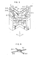
- Fig. 1 is a perspective view of a first embodiment of the support means for the pickup holder used as an actuator according to the invention.
- a driven member 1 such as a pickup holder having secured thereto pickup means for an optical lens, etc., not shown, so as to provide a pickup head, has one end of each of support members 2-1 to 2-8 (which will be generally designated by the numeral 2 when it is not necessary to designate individual support -members) secured thereto, the other end of each of the support members 2-1 to 2-8 being secured to a frame 3.
- the support members 2 are formed of rubber or other viscoelastic material in the form of thread.
- upper fixed ends 31-1 to 31-4 of the support members 2 secured to the frame 3 and lower fixed ends 32-1 to 32-3 thereof secured to the frame 3 (32-4 not being shown) are disposed in first and second planes respectively which are parallel to each other.
- Upper fixed ends 33-1 to 33-4 of the support members 2 secured to the driven member 1 and lower fixed ends 34-2 and 34-3 (34-1 and 34-4 not being shown) thereof secured to the driven member 1 are in third and fourth planes which are parallel to each other.
- the four planes or the first to fourth planes are parallel to each other.
- the support members 2 Before being assembled, the support members 2 have a length smaller than the distance between the driven member 1 and a fixed portion of the frame 3, and the support members 2 are stretched when assembled by applying uniform tension thereto. In driving the driven member 1, coils secured to the driven member 1 and magnetic poles secured to the frame 3 are used. Details of these parts will be subsequently described.
- the driven member 1 By using the construction shown in Fig. 1, it is possible to arrange the driven member 1 in a predetermined position in well-balanced manner, and since the support members 2 are formed of viscoelastic material which is soft, the driven member 1 can move smoothly in any direction when a drive force is exerted thereon in the stationary condition. Moreover, the support members 2 are mainly expanded or contracted no matter in what direction the driven member may move, so that no undesirable resonance phenomenon occurs. Since the support members 2 have their fixed ends disposed in planes parallel to each other, the driven member 1 only has three degrees of freedom for actual purposed in the direction of three axes or x-, y- and z-axes which cross one another, because the three degrees of freedom around these axes are inhibited.
- Fig. 2 is a perspective view of a second embodiment of the support means for supporting the driven member used as an actuator according to the invention.
- the upper and lower support members 2 are parallel to each other.
- this embodiment is constructed such that the first to fourth planes formed by the ends of the support members 2 are parallel to each other.
- the ranges of displacement of the driven member 1 can be set in such a manner that it can move over a wider range in the direction of a z-axis rather than in the direction of an x-axis and in the direction of a y-axis in the indicated order.
- Figs. 3-7 show in perspective views the constructions of third to sixth embodiments of the invention.
- the embodiments shown in Figs. 3-7 are intended to arrange the support members 2 in such a manner that the support members 2 have uniform stiffness in a plane perpendicular to the optical axis (the z-axis in the illustrated embodiments) of an optical system included in the driven member 1.
- the third embodiment shown in Fig. 3 has the number of the support members increased.
- the fourth embodiment shown in Fig. 4 has the number of the support members reduced to three (3) both in the upper and lower layers.
- the fifth embodiment shown in Fig. 5 has a construction enabling some of the support members to be formed integrally, as shown in Fig. 6.
- Fig. 7 shows a sixth embodiment using two support members formed of viscoelastic material in the form of a ring.
- the support members 2 in the form of a ring, it is possible to tentatively support the driven member 1 by the tension alone of the support members 2. While the driven member 1 is in this condition, the driven member 1 may be positioned in a predetermined position and then the support members 2 may be fixed to the driven member 1 and the frame 3 at ends thereof as by means of an adhesive agent.
- the ends of the support members 2 are located such that the first to fourth planes formed by the ends of the support members 2 are parallel to each other, as described by referring to the embodiments shown in Figs. 1 and 2.
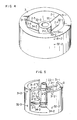
- Fig. 8 is a perspective view of an embodiment which combines support means with drive means for driving the driven member 1 in two directions perpendicular to each other (or the directions of an x-axis and a z-axis shown).
- Fig. 9 in an exploded view of the drive means shown in Fig. 8.
- the driven member 1 comprises an objective lens 4, a lens holder 5, a drive coil 6 for driving in the z-axis direction, and drive coils 7-1, 7-2, 7-3 and 7-4 (generally designated by the numeral 7 when there is no need to specifically designate each coil) for driving in the x-axis direction.
- a magnetic circuit including yokes 8 and 9 and magnets 10-1 and 10-2 is secured to the frame 3.
- the driven member 1 is supported on the frame 3 by the support members 2-1 and 2-2 formed of viscoelastic material in the form of rings in such a manner that the drive coils 6 and 7 are correctly located in a magnetic gap 11.
- the drive coils 6 and 7 having their windings oriented in directions perpendicular to each other, it is possible to obtain drive forces oriented in two directions (the directions of the x-axis and the z-axis, as shown) exerted on the driven member 1 by applying currents to the drive coils 6 and 7.
- the drive forces are exerted symmetrically with respect to the center of gravity of the driven member 1 and the support members 2.
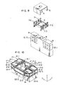
- Fig. 10 is a perspective view of a first embodiment combining support means with drive means for driving the driven member 1 in three directions (the directions of the x-axis, y-axis and z-axis, as shown).
- Fig. 11 is an exploded perspective view of the drive means shown in Fig. 10.
- the driven member 1 comprises an optical system 21, a lens holder 12, drive coils 13-1, 13-2, 13-3 and 13-4 (hereinafter generally designated by 13) for driving in the z-axis, drive coils 14-1, 14-2, 14-3 and 14-4 (hereinafter generally designated by 14) for driving in the x-direction and drive coils 15-1, 15-2, 15-3 and 15-4 (hereinafter generally designated by 15) for driving in the y-axis direction.
- the coils each have leads for supplying an electric current thereto from outside.
- the frame 16 has secured thereto a magnetic circuit including yokes 17-1 to 17-6 (hereinafter generally designated by 17) and 18-1 to 18-6 (hereinafter generally designated by 18) and magnets 19-1 to 19-6 (hereinafter generally designated by 19).
- the driven member 1 is supported on the frame 16 by the support members 2-1 and 2-2 formed by viscoelastic material in the form of rings in such a manner that the drive coils 13, 14 and 15 are correctly located in the magnetic gaps.
- Coil holders 22-1 and 22-2 hold in place coil groups on both sides of the frame 16.
- One coil group C is composed of the drive coils of the z-axis direction 13-1 and 13-4, the drive coils of the x-axis direction 14-1 and 14-4 and the drive coils of the y-axis direction 15-1 and 15-4 forming a pair respectively.
- the two coils forming each pair of drive coils of a different direction are arranged such that they have their windings 'oriented in opposite directions, and the six coils are affixed in a unitary structure.
- the other coil group D is assembled in the same the coil group C.
- the coil groups C and D are connected together by an optical system holder 5' having an optical system 4' secured thereto and the coil holders 22-1 and 22-2.
- the z-axis direction drive coils 13-1 to 13-4 are connected together in such a manner that a current flows in the directions of arrows shown in Fig. 11.
- the x-axis direction and y-axis direction drive coils are also connected together in like manner.
- the magnets 6-1 to 6-6 are magnetized in a vertical direction and arranged in such a manner that the adjacent magnets face opposite directions as shown in Fig. 11.
- magnetic gaps can be formed between the upper yokes 17-1 and 17-2, 17-5 and 17-4 and 17-3 and 17-2, between the lower yokes 18-6 and 18-5, 18-4 and 18-5, 18-2 and 18-3 and 18-2 and 18-1, and between the upper and lower yokes 17-1 and 18-1, 17-6 and 18-6, 17-5 and 18-5, 17-4 and 18-4, 17-3 and 18-3, and 17-2 and 18-2 respectively.
- the support members 21-1 21-2 are formed of rubber or other viscoelastic material, and the driven member 1 is capable of freely moving when a drive force produced by each of the drive coils is exerted thereon. When no drive force is exerted, each drive coil is supported in a correct stationary position in the corresponding magnetic gap.
- the x-axis direction drive coils 14-1 to 14-4 and the z-axis direction drive coils 13-1 to 13-4 have their windings oriented in directions perpendicular to each other in the respective magnetic gaps, so as to enable drive forces to be obtained which extend in two directions perpendicular to each other in one magnetic gap.
- the y-axis direction drive coils 15-1 to 15 ⁇ 4 are located in the magnetic gap which is at a right angle to the aforesaid magnetic gaps, to enable a magnetic force to be obtained which is perpendicular to the aforesaid two directions.
- magnetic gaps betwen parallel members can be used for driving the driven member 1 in three directions which are perpendicular to one another, and it is also possible to insert the coil groups C and D in a magnetic circuit after it is assembled.
- the coil groups C and D can be assembled with the driven member 1 in such a manner that the coil groups C and D are correctly located in the magnetic gaps with ease and the actuator can have its performance improved.
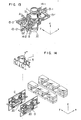
- Fig. 14 is an exploded perspective view of an embodiment for securing drive coils for various axis directions.
- the coil groups C and D are formed into a unitary structure as by an epoxy resin and connected together by an optical system holder 5" having an optical system 4" secured thereto.
- 20 is a terminal section for connecting leads, not shown, for passing an electric current to the drive coils for various axis directions.
- Fig. 12 is a perspective view of the actuator comprising a second embodiment, showing the construction of the drive means
- Fig. 13 is a perspective view of the second embodiment, showing its vibration system.
- two pairs of permanent magnets 19-1 and 19-2 and 19-4 and 19-3 which are vertically magnetized are arranged such that as indicated by the characters N and S in Fig. 12, the adjacent two permanent magnets are magnetized in opposite directions.
- magnetic gaps are formed between the magnetic poles of unlike signs of the adjacent permanent magnets and between the yokes 17-1 and 17-2, 18-1 and 18-2, 17-3 and 17-4 and 18-3 and 18-4 respectively.
- Magnetic gaps are also formed between the magnetic poles of the permanent magnets themselves and between the yokes 17-1 and 18-1, 17-2 and 18-2, 17-3 and 18-3 and 17--4 and 18-4 respectively.
- the driven member 1 including the parts of the optical system comprising the z-axis drive coils 13-1 and 13-2, x-axis drive coils 14-1 and 14-2, y-axis drive coils 15-1 and 15-2 and the objective lens constitutes a vibration system.
- the z-axis direction drive coils 13 and the x-axis drive coils 14 are superposed over each other in such a manner that the axes of their windings are parallel to each other and the directions of the windings are partially perpendicular to each other.
- the y-axis drive coils 15 are arranged such that the axes of their windings are perpendicular to the axes of the windings of the z-axis and x-axis drive coils 13 and 14.
- the x-axis drive coils 14 which are located straddling the two pairs of permanent magnets 19-1 and 19-2 and 19-4 and 19-3 are used also for fixing in place the z-axis direction drive coils 13-1 and 13-2 and the y-axis direction drive coils 15-1 and 15-2.
- the x-axis drive coils 14 are also used for supporting the driven member 1. These coils are formed integrally by high molecular material, such as epoxy resin and securedly fixed in place, to provide a vibration system the details of which are subsequently to be described. As shown in Fig. 12, the vibration system 21 is supported by the support members 2-1 and 2-2 in the magnetic gap in such a manner that it is not in contact with the yokes and it has a space for moving in vibration.
- a line of magnetic force between the yokes 17-3 and 17-4 and a line of magnetic force between the yokes 17-3 and 18-3 are indicated by arrows A and B respectively.
- the x-axis line magnetic coil 14-1 has exerted thereon a force in accordance with the Fleming's left-hand rule, because a path of current 51 forming a part of the path of movement of the coil is disposed in the magnetic field of the line of magnetic force A.
- the x-axis drive coil 14-1 When a current is passed through the path of current 51 in the z-axis negative direction as shown in Fig. 13, the x-axis drive coil 14-1 generates a force oriented in the x-axis positive direction because the magnetic field is in the y-axis positive direction, so that the driven member 1 is displaced in the z-axis positive direction.
- the y-axis drive coil 16-2 when a current is passed in the x-axis positive direction as shown in Fig. 12, the y-axis drive coil 16-2 generates a force oriented in the y-axis positive direction and the driven member 1 is displaced in the y-axis positive direction, because a path of current 52 forming a part of the path of current of the coil is disposed in the magnetic field of the line of magnetic force B.
- the z-axis drive coil 13-2 when a current is passed in the z-axis positive direction as shown in Fig. 13, the z-axis drive coil 13-2 generates a force oriented in the z-axis positive direction and the driven member 1 is displaced in the z-axis positive direction, because a path of current 53 forming a part of the path of current of the coil is disposed in the magnetic field of the line of magnetic force A.
- lines of magnetic force exist between the yokes 17-4 and 18 ⁇ 4, 18-3 and 18 ⁇ 4, 17-1 and 18-1, 17-1 and 17-2 and 18-1 and 18-2. Operation of these lines of magnetic force is similar to those described hereinabove by referring to the lines of magnetic force A and B.
- leads are connected to the end of each of these coils for supplying a current thereto from outside in the same manner as the embodiment shown in Fig. 14.
- the support members 2-1 and 2-2 are formed of viscoelastic material, such as rubber, and the vibration system 21 can move freely by the drive force generated in each coil. Also, in the absence of a drive force, each drive coil is supported in a stationary position in the corresponding magnetic gap.
- the driven member 1 by passing a current selectively to each drive coil, the driven member 1 can be driven to move in a corresponding direction.
- the support members are formed of rubber or other viscoelastic material.
- the presence of the fixing portions of the support members in planes parallel to each other inhibits the degrees of freedom of the direction of rotation of the driven member, so that the driven member moves only in three- axis directions perpendicular to one another. This enables designing of an optical system to be facilitated and allows an overall compact size and reduced costs to be obtained in a support device.
- a driven member can be freely moved in three axis directions perpendicular to one another, so that an optical reproducing apparatus of compact size and capable of adjusting position readily can be provided. Since no movable mirror is used, it is possible to use an objective lens of small angle of field and low costs, thereby reducing the cost of the optical reproducing apparatus.
Landscapes
- Engineering & Computer Science (AREA)
- Physics & Mathematics (AREA)
- Chemical & Material Sciences (AREA)
- Combustion & Propulsion (AREA)
- Electromagnetism (AREA)
- Power Engineering (AREA)
- Optical Recording Or Reproduction (AREA)
Claims (8)
Priority Applications (1)
| Application Number | Priority Date | Filing Date | Title |
|---|---|---|---|
| AT81305578T ATE21294T1 (de) | 1980-11-28 | 1981-11-25 | Einrichtung zur bewegung eines aufnahmekopfes in wenigstens zwei zueinander orthogonalen richtungen. |
Applications Claiming Priority (4)
| Application Number | Priority Date | Filing Date | Title |
|---|---|---|---|
| JP16825380A JPS5792441A (en) | 1980-11-28 | 1980-11-28 | Three-dimensional driving body supporting device |
| JP168253/80 | 1980-11-28 | ||
| JP17097180A JPS5794939A (en) | 1980-12-05 | 1980-12-05 | Three-directional driven-body driver |
| JP170971/80 | 1980-12-05 |
Publications (3)
| Publication Number | Publication Date |
|---|---|
| EP0053476A2 EP0053476A2 (de) | 1982-06-09 |
| EP0053476A3 EP0053476A3 (en) | 1983-01-05 |
| EP0053476B1 true EP0053476B1 (de) | 1986-08-06 |
Family
ID=26492023
Family Applications (1)
| Application Number | Title | Priority Date | Filing Date |
|---|---|---|---|
| EP81305578A Expired EP0053476B1 (de) | 1980-11-28 | 1981-11-25 | Einrichtung zur Bewegung eines Aufnahmekopfes in wenigstens zwei zueinander orthogonalen Richtungen |
Country Status (4)
| Country | Link |
|---|---|
| US (1) | US4592037A (de) |
| EP (1) | EP0053476B1 (de) |
| CA (1) | CA1177167A (de) |
| DE (1) | DE3175073D1 (de) |
Families Citing this family (45)
| Publication number | Priority date | Publication date | Assignee | Title |
|---|---|---|---|---|
| WO1984004841A1 (en) * | 1983-05-31 | 1984-12-06 | Matsushita Electric Industrial Co Ltd | Apparatus for driving objective lens of optical disc player |
| JPS6069841A (ja) * | 1983-09-26 | 1985-04-20 | Toshiba Corp | 光学ヘッド装置 |
| NL8303700A (nl) * | 1983-10-27 | 1985-05-17 | Philips Nv | Electro-optische inrichting. |
| JPS6095735A (ja) * | 1983-10-31 | 1985-05-29 | Hitachi Ltd | 対物レンズ駆動装置 |
| NL8304141A (nl) * | 1983-12-01 | 1985-07-01 | Philips Nv | Electro-optische inrichting voor de electro-dynamische regeling van de positie van een stralingsvlek. |
| JPS60138746A (ja) * | 1983-12-27 | 1985-07-23 | Toshiba Corp | 対物レンズ駆動装置およびその製造方法 |
| US4633456A (en) * | 1984-01-23 | 1986-12-30 | International Business Machines Corporation | Two axis electromagnetic actuator |
| US4813033A (en) * | 1985-10-30 | 1989-03-14 | International Business Machines Corporation | Two axis electromagnetic actuator with axis balanced suspension |
| NL8600437A (nl) * | 1986-02-21 | 1987-09-16 | Philips Nv | Electro-optische inrichting. |
| US4782475A (en) * | 1986-12-22 | 1988-11-01 | Eastman Kodak Company | Flexure supported read head |
| US4779254A (en) * | 1986-12-22 | 1988-10-18 | Eastman Kodak Company | Read head adjusting motor assembly |
| EP0273367B1 (de) * | 1986-12-26 | 1994-02-16 | Kabushiki Kaisha Toshiba | Steuerungsgerät für Objektivlinse |
| NL8700148A (nl) * | 1987-01-21 | 1988-08-16 | Stichting Tech Wetenschapp | Inrichting voor het focusseren van electro-magnetische golven of geluid. |
| JPS63195834A (ja) * | 1987-02-10 | 1988-08-12 | Pioneer Electronic Corp | 可動体支持装置 |
| JPS63257927A (ja) * | 1987-04-15 | 1988-10-25 | Pioneer Electronic Corp | ピツクアツプアクチユエ−タ |
| JPH01113827U (de) * | 1988-01-21 | 1989-07-31 | ||
| JP2683243B2 (ja) * | 1988-03-29 | 1997-11-26 | オリンパス光学工業株式会社 | レンズの支持装置 |
| NL8902615A (nl) * | 1988-11-15 | 1990-06-01 | Seiko Epson Corp | Optisch registratiestelsel. |
| US5206762A (en) * | 1988-12-01 | 1993-04-27 | Kabushiki Kaisha Toshiba | Viscoelastic substance and objective lens driving apparatus with the same |
| JP2537397B2 (ja) * | 1989-03-30 | 1996-09-25 | 旭光学工業株式会社 | 光学式ピックアップ装置 |
| JP2728496B2 (ja) * | 1989-04-21 | 1998-03-18 | 株式会社日立製作所 | 対物レンズ駆動装置 |
| US5265079A (en) | 1991-02-15 | 1993-11-23 | Applied Magnetics Corporation | Seek actuator for optical recording |
| US6141300A (en) * | 1989-06-20 | 2000-10-31 | Discovision Associates | Optical actuator including lens assembly with optical axis having symmetric suspensory forces acting thereon and optical disc system including same |
| US5124965A (en) * | 1989-09-28 | 1992-06-23 | Matsushita Electric Industrial Co., Ltd. | Optical head supporting apparatus |
| US5808980A (en) * | 1991-02-15 | 1998-09-15 | Discovision Associates | Seek actuator for optical recording |
| US6069857A (en) * | 1991-02-15 | 2000-05-30 | Discovision Associates | Optical disc system having improved circuitry for performing blank sector check on readable disc |
| US5677899A (en) * | 1991-02-15 | 1997-10-14 | Discovision Associates | Method for moving carriage assembly from initial position to target position relative to storage medium |
| US5729511A (en) | 1991-02-15 | 1998-03-17 | Discovision Associates | Optical disc system having servo motor and servo error detection assembly operated relative to monitored quad sum signal |
| US6236625B1 (en) | 1991-02-15 | 2001-05-22 | Discovision Associates | Optical disc system having current monitoring circuit with controller for laser driver and method for operating same |
| US5289445A (en) * | 1992-02-11 | 1994-02-22 | International Business Machines Corporation | Suspension system for focus actuator of an optical disk drive |
| US5414563A (en) * | 1992-07-28 | 1995-05-09 | Asahi Kogaku Kogyo Kabushiki Kaisha | Electromagnetic objective lens driving apparatus of optical data recording and reproducing apparatus |
| US6434087B1 (en) | 1995-01-25 | 2002-08-13 | Discovision Associates | Optical disc system and method for controlling bias coil and light source to process information on a storage medium |
| US5748578A (en) * | 1995-01-25 | 1998-05-05 | Discovision Associates | Colpitts type oscillator having reduced ringing and improved optical disc system utilizing same |
| US5920539A (en) * | 1995-01-25 | 1999-07-06 | Discovision Associates | Apparatus and method for suppression of electromagnetic emissions having a groove on an external surface for passing an electrical conductor |
| US6091684A (en) * | 1995-01-25 | 2000-07-18 | Discovision Associates | Optical disc system and method for changing the rotational rate of an information storage medium |
| JPH08273177A (ja) * | 1995-03-31 | 1996-10-18 | Olympus Optical Co Ltd | 光学系駆動装置 |
| JPH0916996A (ja) * | 1995-06-30 | 1997-01-17 | Sony Corp | 二軸アクチュエータ |
| JPH0991725A (ja) * | 1995-09-20 | 1997-04-04 | Matsushita Electric Ind Co Ltd | 光学式情報記録再生装置の光ピックアップ |
| US5986983A (en) * | 1997-11-19 | 1999-11-16 | Eastman Kodak Company | Multiple degrees of freedom actuator for optical recording |
| US6738226B1 (en) | 2000-01-13 | 2004-05-18 | Jpmorgan Chase Bank | Adhesive control features for disc drive head suspension and flex circuit interconnect |
| KR100684011B1 (ko) * | 2000-04-03 | 2007-02-20 | 엘지전자 주식회사 | 광 픽업 엑츄에이터 |
| US6785063B2 (en) * | 2002-08-02 | 2004-08-31 | Acute Applied Technologies, Inc. | Objective lens holding apparatus |
| DE102004018228B4 (de) * | 2004-04-15 | 2006-02-16 | Forschungszentrum Karlsruhe Gmbh | Justageplattform |
| JP2007212876A (ja) * | 2006-02-10 | 2007-08-23 | Sony Corp | 像ぶれ補正装置、レンズ装置及び撮像装置 |
| CN101452107A (zh) * | 2007-12-06 | 2009-06-10 | 鸿富锦精密工业(深圳)有限公司 | 镜头模组及相机模组 |
Family Cites Families (7)
| Publication number | Priority date | Publication date | Assignee | Title |
|---|---|---|---|---|
| US3673412A (en) * | 1970-03-02 | 1972-06-27 | Trw Inc | Radiant energy beam scanning method and apparatus |
| FR2278112A1 (fr) * | 1974-07-12 | 1976-02-06 | Thomson Brandt | Systeme de deflexion optique a commande electrique |
| NL7511634A (nl) * | 1975-10-03 | 1977-04-05 | Philips Nv | Electromagnetisch bestuurbare zwenkspiegelinrich- ting. |
| US4302830A (en) * | 1978-05-10 | 1981-11-24 | Olympus Optical Company Ltd. | Optical information reading-out apparatus |
| FR2443734A1 (fr) * | 1978-12-08 | 1980-07-04 | Thomson Csf | Dispositif d'acces a une piste portee par un support enregistrable ou lisible optiquement et systeme optique comportant un tel dispositif |
| GB2064848B (en) * | 1979-11-12 | 1983-09-14 | Nippon Telegraph & Telephone | Pick up device for use in a video and/or audio information readout apparatus |
| JPS56119944A (en) * | 1980-02-27 | 1981-09-19 | Sony Corp | Disc player |
-
1981
- 1981-11-24 US US06/324,442 patent/US4592037A/en not_active Expired - Fee Related
- 1981-11-25 DE DE8181305578T patent/DE3175073D1/de not_active Expired
- 1981-11-25 EP EP81305578A patent/EP0053476B1/de not_active Expired
- 1981-11-27 CA CA000391118A patent/CA1177167A/en not_active Expired
Also Published As
| Publication number | Publication date |
|---|---|
| CA1177167A (en) | 1984-10-30 |
| US4592037A (en) | 1986-05-27 |
| EP0053476A2 (de) | 1982-06-09 |
| DE3175073D1 (en) | 1986-09-11 |
| EP0053476A3 (en) | 1983-01-05 |
Similar Documents
| Publication | Publication Date | Title |
|---|---|---|
| EP0053476B1 (de) | Einrichtung zur Bewegung eines Aufnahmekopfes in wenigstens zwei zueinander orthogonalen Richtungen | |
| US4538882A (en) | Two-dimensional suspension | |
| US5602808A (en) | Objective lens driving apparatus | |
| US4570249A (en) | Optical read/write head for recording and playback of an optical disk and an optical device associated with said optical head | |
| US4818066A (en) | Objective lens driving device | |
| JPH07302430A (ja) | 光ディスクプレーヤーの光ピックアップアクチュエーター | |
| JP2565783Y2 (ja) | スライド変位装置 | |
| EP0625779B1 (de) | Betätigungseinrichtung für optischen Kopf | |
| KR930011446B1 (ko) | 트랜스듀우서 구동장치 | |
| US5428589A (en) | Apparatus and method for an electromagnetic actuator with two orthogonal axes of motion | |
| JPH0345366B2 (de) | ||
| EP0762395A1 (de) | Haltevorrichtung für Objektivlinse | |
| US6996039B2 (en) | Optical pick-up actuator | |
| JP2798992B2 (ja) | 情報記録再生装置 | |
| JPH0343694B2 (de) | ||
| KR100713544B1 (ko) | 광 픽업 액츄에이터 | |
| JP2766886B2 (ja) | 光ピックアップのトラッキング及びフォーカシングサーボ追随用機構 | |
| JP2004139642A (ja) | 対物レンズアクチュエータ | |
| US7924665B2 (en) | Pickup device and recording medium drive unit | |
| JPH05135404A (ja) | 光ヘツドアクチユエータの製造方法 | |
| JPS60253030A (ja) | 対物レンズ駆動装置 | |
| JP2605958B2 (ja) | 支持装置 | |
| JPS63104227A (ja) | 対物レンズ支持装置 | |
| JPH10162394A (ja) | 対物レンズ駆動装置 | |
| JPH0675294B2 (ja) | 対物レンズ駆動装置 |
Legal Events
| Date | Code | Title | Description |
|---|---|---|---|
| PUAI | Public reference made under article 153(3) epc to a published international application that has entered the european phase |
Free format text: ORIGINAL CODE: 0009012 |
|
| AK | Designated contracting states |
Designated state(s): AT CH DE GB |
|
| PUAL | Search report despatched |
Free format text: ORIGINAL CODE: 0009013 |
|
| AK | Designated contracting states |
Designated state(s): AT CH DE GB LI |
|
| 17P | Request for examination filed |
Effective date: 19830528 |
|
| GRAA | (expected) grant |
Free format text: ORIGINAL CODE: 0009210 |
|
| AK | Designated contracting states |
Kind code of ref document: B1 Designated state(s): AT CH DE GB LI |
|
| REF | Corresponds to: |
Ref document number: 21294 Country of ref document: AT Date of ref document: 19860815 Kind code of ref document: T |
|
| REF | Corresponds to: |
Ref document number: 3175073 Country of ref document: DE Date of ref document: 19860911 |
|
| PGFP | Annual fee paid to national office [announced via postgrant information from national office to epo] |
Ref country code: AT Payment date: 19861021 Year of fee payment: 6 |
|
| PLBE | No opposition filed within time limit |
Free format text: ORIGINAL CODE: 0009261 |
|
| STAA | Information on the status of an ep patent application or granted ep patent |
Free format text: STATUS: NO OPPOSITION FILED WITHIN TIME LIMIT |
|
| 26N | No opposition filed | ||
| PG25 | Lapsed in a contracting state [announced via postgrant information from national office to epo] |
Ref country code: AT Effective date: 19871125 |
|
| PG25 | Lapsed in a contracting state [announced via postgrant information from national office to epo] |
Ref country code: LI Effective date: 19871130 Ref country code: CH Effective date: 19871130 |
|
| GBPC | Gb: european patent ceased through non-payment of renewal fee | ||
| REG | Reference to a national code |
Ref country code: CH Ref legal event code: PL |
|
| PG25 | Lapsed in a contracting state [announced via postgrant information from national office to epo] |
Ref country code: DE Effective date: 19880802 |
|
| PG25 | Lapsed in a contracting state [announced via postgrant information from national office to epo] |
Ref country code: GB Effective date: 19881118 |