EP0047821B1 - Wegstreckenzähler - Google Patents
Wegstreckenzähler Download PDFInfo
- Publication number
- EP0047821B1 EP0047821B1 EP81105130A EP81105130A EP0047821B1 EP 0047821 B1 EP0047821 B1 EP 0047821B1 EP 81105130 A EP81105130 A EP 81105130A EP 81105130 A EP81105130 A EP 81105130A EP 0047821 B1 EP0047821 B1 EP 0047821B1
- Authority
- EP
- European Patent Office
- Prior art keywords
- wheel
- arm
- selected number
- recess
- projects
- Prior art date
- Legal status (The legal status is an assumption and is not a legal conclusion. Google has not performed a legal analysis and makes no representation as to the accuracy of the status listed.)
- Expired
Links
Images

Classifications
-
- G—PHYSICS
- G06—COMPUTING OR CALCULATING; COUNTING
- G06M—COUNTING MECHANISMS; COUNTING OF OBJECTS NOT OTHERWISE PROVIDED FOR
- G06M3/00—Counters with additional facilities
- G06M3/02—Counters with additional facilities for performing an operation at a predetermined value of the count, e.g. arresting a machine
- G06M3/021—Counters with additional facilities for performing an operation at a predetermined value of the count, e.g. arresting a machine with drums type indicating means
- G06M3/024—Counters with additional facilities for performing an operation at a predetermined value of the count, e.g. arresting a machine with drums type indicating means by adding
-
- G—PHYSICS
- G01—MEASURING; TESTING
- G01C—MEASURING DISTANCES, LEVELS OR BEARINGS; SURVEYING; NAVIGATION; GYROSCOPIC INSTRUMENTS; PHOTOGRAMMETRY OR VIDEOGRAMMETRY
- G01C22/00—Measuring distance traversed on the ground by vehicles, persons, animals or other moving solid bodies, e.g. using odometers, using pedometers
-
- G—PHYSICS
- G06—COMPUTING OR CALCULATING; COUNTING
- G06M—COUNTING MECHANISMS; COUNTING OF OBJECTS NOT OTHERWISE PROVIDED FOR
- G06M1/00—Design features of general application
- G06M1/22—Design features of general application for visual indication of the result of count on counting mechanisms, e.g. by window with magnifying lens
- G06M1/24—Drums; Dials; Pointers
- G06M1/241—Drums
Definitions
- the invention relates to a odometer with a counter axis, on which side by side number rollers are rotatably mounted, which are labeled with the numbers 0-9 evenly distributed on their cylindrical circumference, a number of the adjacent numbers being visible in a viewing window, with a drive the number rolls, by which the adjacent number roll is rotated by a 9/10 rotation in the order from right to left when one turn of a number roll is completed and with a display device which can be actuated by a selected number roll when a specific display position is reached, with a display flag which corresponds to the the selected number roller is coupled together and can be moved to the viewing window when the specific display position is reached, can be uncoupled from the selected number roller and can be locked in this position.
- Such a odometer is known from US-A No. 4160900, which has an axially protruding pin on its outer left numerical roller in order to indicate that a certain distance has been covered by a special display device.
- this pin strikes one arm of a two-armed lever and pivots it.
- the other arm interrupts a magnetic field so that the display device acted upon by the magnetic field is switched on or off.
- This known odometer has a very complex structure consisting of high-quality and expensive components, which also requires a relatively large installation space.
- a distance counter with a pin which also projects axially from the outer left-hand roller for adjusting a display flag is known from US-A No. 1948427.
- the coupling or uncoupling mechanism has a component-intensive structure.
- the object of the invention is to provide a distance counter which has a simple structure with high operational reliability and requires only a small installation space.
- the spring arm is rotatably mounted on the counter axis and is formed with two arms projecting radially away from the counter axis, the indicator flag being arranged at the free end of one arm and the free end of the other arm in the recess of the selected number roller protrudes.
- the end of the arm protruding into the recess of the number roller has an axially directed bend which projects into the recess of the number roller when the spring arm is preloaded and into an axial recess of the wall when the spring arm is relaxed, it being favorable if the bend is U-shaped .
- the spring arm has an axial extension, which ensures secure engagement in the recess in the selected number roller or in the wall.
- the indicator flag can be formed by the angled free end of the arm projecting axially into the region of the viewing window.
- the indicator flag can also have a color coating so that it reliably draws the observer's attention to the condition to be displayed.
- the indicator flag is assigned to the left outer number roll, which generally shows the tens of thousands of kilometers, it can be used to indicate that hundreds of thousands of kilometers have been exceeded.
- the odometer shown in the figures, in particular in FIG. 2, consists of a number roller 2, 2 'rotatably mounted on a counter axis 1.
- the number rollers 2, 2 ' can be rotatably driven by a drive 3 in such a way that the number roller 2, 2' located next to it is rotated by a 9/10 revolution in the order from right to left when one revolution of a number roller 2 ends.
- a spring arm 4 shown as an individual part in FIGS. 3 and 4, with an indicator flag 5 is arranged on the outer left number roller 2 '.
- the spring arm 4 is on the Counter axis 1 rotatably mounted and has two radially projecting arms 6 and 7.
- the free end of the arm 6 is angled and projects axially into the area of the number roller 2 'labeled with the numbers. This free end, which can also be colored, forms the display flag 5.
- the free end of the arm 7 is designed as a U-shaped bend 8 and protrudes axially from the plane of the spring arm 4.
- the bend 8 In the normal position, in which the bend 8 is drawn with a solid line, the bend 8 is supported on a fixed wall 9 arranged parallel to the number roll 2 'and protrudes into a recess 10 in the end wall of the number roll 2'. Since the recess 10 is delimited in the circumferential direction by the webs 11, the spring arm 4 is connected in a rotationally fixed manner to the number roller 2 'in this normal position.
- the bend 8 of the spring arm 4 rotating with the number roller 2' reaches a recess 11 in the non-rotatable wall 9 and latches, since it had previously been bent into the recess 10 so as to be preloaded, in the recess 11 a. In this position, the turn 8 is shown by a broken line.
- the indicator flag 5 arranged on the arm 6 also protrudes into the area of the number roller 2, 2 'which is visible to the observer through the viewing window and thus indicates that all the number rollers 2, 2' have already made one full revolution, that is to say already a distance of more than a hundred thousand kilometers was covered.
Landscapes
- Physics & Mathematics (AREA)
- Engineering & Computer Science (AREA)
- General Physics & Mathematics (AREA)
- Theoretical Computer Science (AREA)
- Radar, Positioning & Navigation (AREA)
- Remote Sensing (AREA)
- Measurement Of Distances Traversed On The Ground (AREA)
Description
- Die Erfindung bezieht sich auf einen Wegstrekkenzähler mit einer Zählerachse, auf der nebeneinander Zahlenrollen drehbar gelagert sind, die auf ihrem zylindrischen Umfang gleichmässig verteilt mit den Ziffern 0-9 beschriftet sind, wobei eine Reihe der nebeneinanderliegenden Ziffern in einem Sichtfenster sichtbar ist, mit einem Antrieb derZahlenrollen, durch den in der Reihenfolge von rechts nach links bei Beendigung einer Umdrehung einer Zahlenrolle die danebenliegende Zahlenrolle um eine 9/10-Umdrehung gedreht wird und mit einer durch eine ausgewählte Zahlenrolle bei Erreichen einer bestimmten Anzeigeposition betätigbaren Anzeigeeinrichtung mit einer Anzeigefahne, die mit der ausgewählten Zahlenrolle zusammengekuppelt und bei Erreichen der bestimmten Anzeigeposition in den Bereich des Sichtfensters bewegbar, von der ausgewählten Zahlenrolle abkuppelbar und in dieser Position arretierbar ist.
- Aus der US-A Nr. 4160900 ist ein derartiger Wegstreckenzähler bekannt, der, um das Erreichen einer bestimmten zurückgelegten Wegstrecke durch eine besondere Anzeigeeinrichtung anzuzeigen, an seiner äusseren linken Zahlenrolle einen axial hervorstehenden Zapfen besitzt. Bei Verdrehen der Zahlenrolle in einem bestimmten Bereich schlägt dieser Zapfen an dem einen Arm eines zweiarmigen Hebels an und verschwenkt diesen. Dadurch greift der andere Arm unterbrechend in ein Magnetfeld ein, so dass die von dem Magnetfeld beaufschlagte Anzeigeeinrichtung ein- bzw. ausgeschaltet wird.
- Dieser bekannte Wegstreckenzähler hat einen sehr aufwendigen aus hochwertigen und teuren Bauteilen bestehenden Aufbau, der darüber hinaus auch noch einen relativ grossen Einbauraum benötigt.
- Ein Wegstreckenzähler mit ebenfalls einem axial von der äusseren linken Zahlenrolle hervorstehenden Zapfen zum Verstellen einer Anzeigefahne ist aus der US-A Nr. 1948427 bekannt. Der Kuppel- bzw. Entkuppelmechanismus weist dabei einen bauteilaufwendigen Aufbau auf.
- Ein weiterer Wegstreckenzähler der eingangs genannten Art ist aus der US-A Nr. 2493437 bekannt. Er besitzt eine federnd die äusserste linke Zahlenrolle umgreifende Klammer, an der die Anzeigefahne befestigt ist. Durch die Erschütterungen während des Fahrbetriebs kann die Klammer sich aus ihrer Einstellposition wegbewegen, so dass ihre Anzeige im Sichtfenster nicht mehr dem gewünschten Zeitpunkt entspricht.
- Aufgabe der Erfindung ist es, einen Wegstrekkenzähler zu schaffen, der bei hoher Betriebssicherheit einen einfachen Aufbau besitzt und nur einen geringen Einbauraum erfordert.
- Diese Aufgabe wird erfindungsgemäss durch den Gegenstand des Anspruchs 1 gelöst.
- Auf aufwendige, einen grossen Einbauraum erfordernde Einrichtungen kann verzichtet werden und mit einfachen Mitteln kann eine Anzeige des Erreichens einer bestimmten zurückgelegten Wegstrecke erfolgen.
- Diese Vorteile gelten insbesondere, wenn der Federarm drehbar auf der Zählerachse gelagert und mit zwei von der Zählerachse radial wegragenden Armen ausgebildet ist, wobei an dem freien Ende des einen Armes die Anzeigefahne angeordnet ist und das freie Ende des anderen Armes in die Ausnehmung der ausgewählten Zahlenrolle hineinragt.
- Vorzugsweise besitzt das in die Ausnehmung der Zahlenrolle hineinragende Ende des Armes eine axial gerichtete Abbiegung, die bei vorgespanntem Federarm in die Ausnehmung der Zahlenrolle und bei entspanntem Federarm in eine axiale Ausnehmung der Wand hineinragt, wobei es günstig ist, wenn die Abbiegung U-förmig ist. Durch diese Abbiegung hat der Federarm eine axiale Erstreckung, die ein sicheres Eingreifen in die Ausnehmung in der ausgewählten Zahlenrolle bzw. in der Wand gewährleistet.
- Die Anzeigefahne kann durch das abgewinkelte axial in den Bereich des Sichtfensters ragende freie Ende des Armes gebildet sein. Dabei kann die Anzeigefahne noch eine Farbbeschichtung aufweisen, so dass sie den Beobachter sicher auf den anzuzeigenden Zustand aufmerksam macht.
- Ist die Anzeigefahne der linken äusseren Zahlenrolle zugeordnet, die im allgemeinen die Zehntausender Kilometer anzeigt, so kann damit angezeigt werden, dass hundertausend Kilometer überschritten wurden.
- Ein Ausführungsbeispiel der Erfindung ist in der Zeichnung dargestellt und wird im folgenden näher beschrieben. Es zeigen:
- Fig. 1 eine Zahlenrolle eines erfindungsgemässen Wegstreckenzählers im Schnitt;
- Fig. 2 eine perspektivische Ansicht von auf einer Zählerachse angeordneten Zahlenrolle;
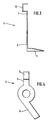
- Fig. 3 eine Ansicht der Anzeigefahne aus Fig. 1;
- Fig. 4 die Anzeigefahne nach Fig. 3 in der Seitenansicht.
- Der in den Figuren, insbesondere in Fig. 2, dargestellte Wegstreckenzähler besteht aus auf einer Zählerachse 1 drehbar gelagerten Zahlenrolle 2,2'. Die Zahlenrollen 2, 2'sind auf ihrem zylindrischen Umfang gleichmässig verteilt mit den Ziffern 0-9 beschriftet. Dabei sind die Ziffern der Zahlenrolle 2,2' nebeneinanderliegend jeweils in einer Reihe. Eine Reihe dieser Ziffern ist durch ein Sichtfenster einer nicht dargestellten zwischen einem Beobachter und dem Wegstreckenzähler angeordneten Abdeckung sichtbar. Durch einen Antrieb 3 sind die Zahlenrollen 2, 2' derart drehbar antreibbar, dass in der Reihenfolge von rechts nach links bei Beendigung einer Umdrehung einer Zahlenrolle 2 die danebenliegende Zahlenrolle 2, 2' um eine 9/10-Umdrehung gedreht wird.
- Wie in Fig. 1 zu sehen ist, ist an der äusseren linken Zahlenrolle 2' ein in den Fig. 3 und 4 als Einzelteil dargestellter Federarm 4 mit einer Anzeigefahne 5 angeordnet. Der Federarm 4 ist auf der Zählerachse 1 drehbar gelagert und weist zwei radial wegragende Arme 6 und 7 auf. Das freie Ende des Armes 6 ist abgewinkelt und ragt axial in den mit den Ziffern beschrifteten Bereich der Zahlenrolle 2'. Dieses freie Ende, das auch farbig angelegt sein kann, bildet die Anzeigefahne 5.
- Das freie Ende des Armes 7 ist als U-förmige Abbiegung 8 ausgebildet und steht axial aus der Ebene des Federarmes 4 hervor.
- In der Normallage, in der die Abbiegung 8 mit durchgezogenem Strich gezeichnet ist, ist die Abbiegung 8 an einer parallel neben der Zahlenrolle 2' angeordneten feststehenden Wand 9 abgestützt und ragt in eine Ausnehmung 10 in der Stirnwand der Zahlenrolle 2' hinein. Da die Ausnehmung 10 in Umfangsrichtung durch die Stege 11 begrenzt ist, ist in dieser Normallage der Federarm 4 drehfest mit der Zahlenrolle 2' verbunden.
- Hat die Zahlenrolle 2' eine volle Umdrehung gemacht, so erreicht die Abbiegung 8 des sich mit der Zahlenrolle 2' drehenden Federarmes 4 eine Ausnehmung 11 in der drehfesten Wand 9 und rastet, da sie vorher unter Vorspannung in die Ausnehmung 10 ragend abgebogen war, in die Ausnehmung 11 ein. In dieser Stellung ist die Abbiegung 8 durch eine unterbrochene Linie dargestellt.
- Durch das Einrasten der Abbiegung 8 in die Ausnehmung 11, wird die drehfeste Verbindung zwischen Zahlenrolle 2' und Federarm 4 gelöst. Gleichzeitig ist der Federarm 4 durch seine in die Ausnehmung 11 eingerastete Abbiegung 8 drehfest mit der Wand 9 verbunden und bleibt in dieser Lage stehen.
- In dieser Lage ragt aber auch die an dem Arm 6 angeordnete Anzeigefahne 5 in den durch das Sichtfenster vom Beobachter sichtbaren Bereich der Zahlenrolle 2, 2' und zeigt damit an, dass alle Zahlenrollen 2, 2' bereits eine volle Umdrehung gemacht haben, also bereits eine Wegstrecke von mehr als hunderttausend Kilometern zurückgelegt wurde.
Claims (7)
Applications Claiming Priority (2)
| Application Number | Priority Date | Filing Date | Title |
|---|---|---|---|
| DE19803034587 DE3034587A1 (de) | 1980-09-13 | 1980-09-13 | Wegstreckenzaehler |
| DE3034587 | 1980-09-13 |
Publications (2)
| Publication Number | Publication Date |
|---|---|
| EP0047821A1 EP0047821A1 (de) | 1982-03-24 |
| EP0047821B1 true EP0047821B1 (de) | 1984-03-28 |
Family
ID=6111862
Family Applications (1)
| Application Number | Title | Priority Date | Filing Date |
|---|---|---|---|
| EP81105130A Expired EP0047821B1 (de) | 1980-09-13 | 1981-07-02 | Wegstreckenzähler |
Country Status (3)
| Country | Link |
|---|---|
| EP (1) | EP0047821B1 (de) |
| AU (1) | AU553140B2 (de) |
| DE (2) | DE3034587A1 (de) |
Family Cites Families (3)
| Publication number | Priority date | Publication date | Assignee | Title |
|---|---|---|---|---|
| US1948427A (en) * | 1932-12-02 | 1934-02-20 | Arnoid H Moecker | Oil mileage indicator |
| US2493437A (en) * | 1946-10-11 | 1950-01-03 | Howard L Berry | Signal device |
| US3965847A (en) * | 1975-04-03 | 1976-06-29 | General Motors Corporation | Service minder odometer |
-
1980
- 1980-09-13 DE DE19803034587 patent/DE3034587A1/de not_active Withdrawn
-
1981
- 1981-07-02 EP EP81105130A patent/EP0047821B1/de not_active Expired
- 1981-07-02 DE DE8181105130T patent/DE3162879D1/de not_active Expired
- 1981-08-24 AU AU74473/81A patent/AU553140B2/en not_active Ceased
Also Published As
| Publication number | Publication date |
|---|---|
| DE3034587A1 (de) | 1982-04-29 |
| DE3162879D1 (en) | 1984-05-03 |
| AU7447381A (en) | 1982-03-25 |
| EP0047821A1 (de) | 1982-03-24 |
| AU553140B2 (en) | 1986-07-03 |
Similar Documents
| Publication | Publication Date | Title |
|---|---|---|
| DE2536346C3 (de) | Vorrichtung zur Anzeige durchzuführender Wartungsarbeiten an einem Fahrzeug | |
| DE1425903B2 (de) | Drehscheingungslager fuer zwei koaxiale relativ zueinander begrenzt verdrehbare bauteile | |
| EP0047821A1 (de) | Wegstreckenzähler | |
| DE2751045C2 (de) | Mechanisches Zählwerk | |
| DE3400936A1 (de) | Rollenzaehlwerk eines wasserzaehlers mit einer in seinem gehaeuse drehbar gelagerten zahlenrolle | |
| DE559965C (de) | Selbstverkaeufer zum wahlweisen Entnehmen einer bestimmten oder mehrerer Warenmengen, insbesondere einer bandfoermigen Ware | |
| DE822812C (de) | Sperreinrichtung mit federloser Klinke | |
| DE682510C (de) | Verfahren zur UEbertragung von Zahlen, Worten oder sonstigen Zeichen | |
| DE878289C (de) | Zaehler mit waehlbarer Ziffereinstellung | |
| DE2500853A1 (de) | Fluidabgabesystem | |
| DE898234C (de) | Addierwerksein- und -ausrueckmechanismus fuer Registrierkassen, Buchungs- und aehnliche Maschinen | |
| DE617285C (de) | Zaehlvorrichtung zum selbsttaetigen Unterbrechen des Zaehlvorganges und zum Ausloesen einer Vorsignal-, Signal- oder Ausrueckevorrichtung | |
| DE376806C (de) | Schreibwerk, das die einzelnen Ausschlaege eines von einem Elektrizitaetszaehler angetriebenen, durch eine Uhr periodisch vom Zaehler abgekuppelten Maximumzaehlwerks aufzeichnet | |
| DE635562C (de) | Umstellvorrichtung fuer Wechselzifferblaetter | |
| DE1750606A1 (de) | Herznocken-Rueckstellvorrichtung | |
| DE398944C (de) | Rechenmaschine | |
| AT41949B (de) | Rechenmaschine. | |
| DE909798C (de) | Schrittantrieb fuer Anzeigewerke | |
| AT152170B (de) | Nullendruckvorrichtung und Schaltwerk für Registrierkassen oder Buchungsmaschinen. | |
| DE1774745C (de) | Einstellwerk fur Gruppen von Anzeige radern und von Typenrädern an preis rechnenden Waagen | |
| DE1425903C (de) | Drehschwingungslager für zwei koaxiale, relativ zueinander begrenzt verdrehbare Bauteile | |
| AT65805B (de) | Vorrichtung an Thomas'schen Rechenmaschinen zum Abkuppeln der Zählscheiben von ihrem Antriebswerk. | |
| CH257146A (de) | Zehnerübertragungsvorrichtung an rechnenden Bureaumaschinen. | |
| AT35116B (de) | Fahrpreisanzeiger. | |
| DE272585C (de) |
Legal Events
| Date | Code | Title | Description |
|---|---|---|---|
| PUAI | Public reference made under article 153(3) epc to a published international application that has entered the european phase |
Free format text: ORIGINAL CODE: 0009012 |
|
| AK | Designated contracting states |
Designated state(s): DE FR GB SE |
|
| 17P | Request for examination filed |
Effective date: 19820204 |
|
| GRAA | (expected) grant |
Free format text: ORIGINAL CODE: 0009210 |
|
| AK | Designated contracting states |
Designated state(s): DE FR GB SE |
|
| REF | Corresponds to: |
Ref document number: 3162879 Country of ref document: DE Date of ref document: 19840503 |
|
| ET | Fr: translation filed | ||
| PGFP | Annual fee paid to national office [announced via postgrant information from national office to epo] |
Ref country code: DE Payment date: 19840622 Year of fee payment: 4 |
|
| PGFP | Annual fee paid to national office [announced via postgrant information from national office to epo] |
Ref country code: SE Payment date: 19840630 Year of fee payment: 4 |
|
| PGFP | Annual fee paid to national office [announced via postgrant information from national office to epo] |
Ref country code: FR Payment date: 19840702 Year of fee payment: 4 |
|
| PLBE | No opposition filed within time limit |
Free format text: ORIGINAL CODE: 0009261 |
|
| STAA | Information on the status of an ep patent application or granted ep patent |
Free format text: STATUS: NO OPPOSITION FILED WITHIN TIME LIMIT |
|
| 26N | No opposition filed | ||
| PG25 | Lapsed in a contracting state [announced via postgrant information from national office to epo] |
Ref country code: GB Effective date: 19880702 |
|
| PG25 | Lapsed in a contracting state [announced via postgrant information from national office to epo] |
Ref country code: SE Effective date: 19880703 |
|
| GBPC | Gb: european patent ceased through non-payment of renewal fee | ||
| PG25 | Lapsed in a contracting state [announced via postgrant information from national office to epo] |
Ref country code: FR Free format text: LAPSE BECAUSE OF NON-PAYMENT OF DUE FEES Effective date: 19890331 |
|
| PG25 | Lapsed in a contracting state [announced via postgrant information from national office to epo] |
Ref country code: DE Effective date: 19890401 |
|
| REG | Reference to a national code |
Ref country code: FR Ref legal event code: ST |
|
| EUG | Se: european patent has lapsed |
Ref document number: 81105130.9 Effective date: 19890510 |