EP0044404B1 - Frachtladesystem für Grossraumflugzeuge - Google Patents
Frachtladesystem für Grossraumflugzeuge Download PDFInfo
- Publication number
- EP0044404B1 EP0044404B1 EP81104572A EP81104572A EP0044404B1 EP 0044404 B1 EP0044404 B1 EP 0044404B1 EP 81104572 A EP81104572 A EP 81104572A EP 81104572 A EP81104572 A EP 81104572A EP 0044404 B1 EP0044404 B1 EP 0044404B1
- Authority
- EP
- European Patent Office
- Prior art keywords
- bolt
- claws
- release
- way
- lever
- Prior art date
- Legal status (The legal status is an assumption and is not a legal conclusion. Google has not performed a legal analysis and makes no representation as to the accuracy of the status listed.)
- Expired
Links
- 210000000078 claw Anatomy 0.000 claims description 25
- 238000010276 construction Methods 0.000 description 1
- 238000000034 method Methods 0.000 description 1
Images

Classifications
-
- B—PERFORMING OPERATIONS; TRANSPORTING
- B64—AIRCRAFT; AVIATION; COSMONAUTICS
- B64D—EQUIPMENT FOR FITTING IN OR TO AIRCRAFT; FLIGHT SUITS; PARACHUTES; ARRANGEMENT OR MOUNTING OF POWER PLANTS OR PROPULSION TRANSMISSIONS IN AIRCRAFT
- B64D9/00—Equipment for handling freight; Equipment for facilitating passenger embarkation or the like
- B64D9/003—Devices for retaining pallets or freight containers
-
- B—PERFORMING OPERATIONS; TRANSPORTING
- B60—VEHICLES IN GENERAL
- B60P—VEHICLES ADAPTED FOR LOAD TRANSPORTATION OR TO TRANSPORT, TO CARRY, OR TO COMPRISE SPECIAL LOADS OR OBJECTS
- B60P7/00—Securing or covering of load on vehicles
- B60P7/06—Securing of load
- B60P7/13—Securing freight containers or forwarding containers on vehicles
Definitions
- the invention relates to a cargo loading system for underfloor cargo spaces in wide-body aircraft for loading with containers and pallets, in each of which a container and pallet bolt has two locking claws, which are operatively connected to one another via a release lever so that the latter moves in a predetermined manner when the air cargo is moved Triggers a release of the bolt and prevents a bolt release when moving in the opposite direction, the bolt claws being pivoted in via a foot lever and one of the bolt claws being lockable in the lowered position.
- the present invention has for its object to expand this known bolt so that the manually operated charging system can be converted by semi-automatic or fully automatic operation by optionally assigning electrical and electronic components without the mechanical bolt components having to be changed in terms of construction and function.
- Pallet bar 200 consists of a housing 1, the locking claws 2, 3, which are rotatably connected to the housing 1 by means of the bolts 4, 5.
- the locking claws 2, 3 are locked in the erected position via the wedge surfaces 2a, 3a of these locking claws and the housing support 3b and are also held in this position by the torsion springs 4a, 5a.
- the foot lift 6 arranged on the side of the latch claw 2 is for lowering the latch for the loading process.
- the release lever 8 On the axis 7, the release lever 8 is pivotally mounted with the two torsion springs 7a and is connected to the holding cam 10 with the bolt 8a via the push rod 9.
- the push rod 9 has an elongated hole 9a and a retaining bolt 9b.
- the holding cam 10 is rotatably mounted on the shaft 11 and articulated with the bolt 12 via the push rod 9 with the release lever 8.
- the retaining cam 10 is pressed against the nose 2b of the locking claw 2 by the torsion spring 11a.
- the foot button 13 is rotatably mounted on the axis 14 and is pressed against the stop 15 by the spring 14a. Via the bolt 16 and the connecting lever 17, the foot button 13 is connected to the hook lever 18, which is rotatably arranged on the bolt 19.
- a limit switch 20 is installed for the semi-automatic and a lifting magnet 21 is installed for the fully automatic, which is hooked into the connecting bolt 2c of the locking claw 2 via the pull rod 21a and replaces the actuation of the foot button 6.
- These electrical components can be installed without changing the mechanics.
- the proposed embodiment works as follows: If the container or plate latch 200 is pressed down with the foot lever 6 in the direction of arrow A, the latch claw 2 swivels downward about the pivot point 4 and thereby tensioning the torsion spring 4a.
- the relatively weak, preloaded torsion spring 5a moves the locking claw 3 around the bolt 5, that is, it runs in the direction of the locking claw 2.
- the roller 6a rolls on the backdrop 3c of the locking claw 3.
- the nose 2b of the locking claw 2 swivels upward and presses the holding cam 10, which is mounted on the shaft 11, backwards.
- the push rod 9 is also pulled to the rear and thereby slides in the slot 9a on the bolt 8a of the release lever 8.
- the holding cam 10 pivots about the shaft 11 under spring tension 11a under the nose 2b of the locking claw 2.
- the latch is now lowered and the air cargo can be unloaded.
- the release lever 8 When unloading, the release lever 8 is moved by the air cargo 201 or container or pallet in the direction of arrow B.
- the bolt 8a of the release lever 8 moves in the slot 9a of the push rod 9 to the rear. There is therefore no release of the bolt when unloading.
- the release lever 8 When loading, however, the release lever 8 is moved by the air cargo 201 in the direction of arrow C.
- the bolt 8a of the release lever 8 presses the push rod 9 against the bolt 12 and thus rotates the retaining cam 10 about the shaft 11 from the locking position.
- the prestressed torsion spring 4a pivots the locking claw 2 upwards about the bolt 4.
- the roller 6a which runs along the link 3c of the locking claw 3, also presses the latter upwards.
- the locking claws 2, 3 are locked in the erected position via the wedge surfaces 2a, 3a and the housing support 3b. The air cargo is thus kept at the parking space.
- a release lock is possible after the latch has been lowered via the foot lever 6 by swiveling the release lever 8 down in the direction of arrow B.
- the bolt 8a slides in the slot 9a of the push rod 9 and presses it down until the retaining bolt 9b engages in the hook lever 18.
- the release lever 8 can no longer be reached by the air cargo 201, and the lock therefore remains in the lowered position.
- the hook lever 18 is pivoted out about the pin 19 via the connecting lever 17 and releases the retaining pin 9b.
- the torsion spring 7a pivots the Release lever 8 around axis 7 in the working position.
- the trigger lever 8 is held in the working position by the two counter-rotating torsion springs 7a.
Landscapes
- Engineering & Computer Science (AREA)
- Aviation & Aerospace Engineering (AREA)
- Transportation (AREA)
- Mechanical Engineering (AREA)
- Connection Of Plates (AREA)
- Loading Or Unloading Of Vehicles (AREA)
- Pallets (AREA)
- Load-Engaging Elements For Cranes (AREA)
- Fittings On The Vehicle Exterior For Carrying Loads, And Devices For Holding Or Mounting Articles (AREA)
Description
- Die Erfindung bezieht sich auf ein Frachtladesystem für Unterflurfrachträume in Grossraumflugzeugen zur Beladung mit Containern und Paletten, in dem jeweils ein Container- und Palettenriegel zwei Riegelklauen aufweist, die miteinander über einen Auslösehebel so in Wirkverbindung stehen, dass letzterer bei der Bewegung des Luftfrachtgutes in einer vorgegebenen Richtung eine Auslösung des Riegels bewirkt und bei der Bewegung in der Gegenrichtung eine Riegelauslösung vermieden wird, wobei die Riegelklauen über einen Fusshebel einschwenkbar angeordnet sind und die eine der Riegelklauen in der abgesenkten Stellung sperrbar ist.
- Ein solches Frachtladesystem ist aus der DE-AS 2 432 245 der Anmelderin bekannt geworden.
- Der vorliegenden Erfindung liegt die Aufgabe zugrunde, diesen bekannten Riegel so auszubauen, dass das manuell bedienbare Ladesystem durch wahlweise Zuordnung elektrischer und elektronischer Bauteile für halb- oder vollautomatischen Betrieb umrüstbar ist, ohne dass die mechanischen Riegelkomponenten konstruktionsmässig und funktionell verändert werden müssen.
- Diese Aufgabe wird durch die im Anspruch 1 niedergelegten Massnahmen gelöst. Im Unteranspruch ist eine vorteilhafte Ausgestaltung aufgezeigt und in der nachfolgenden Beschreibung wird ein Ausführungsbeispiel erläutert, das in den Figuren der Zeichnung dargestellt ist. Es zeigen
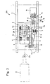
- Fig. 1 eine Seitenansicht der Verriegelung in der verriegelten Position,
- Fig. 2 eine Draufsicht gemäss Fig. 1,
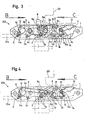
- Fig. 3 eine Seitenansicht der Verriegelung in abgesenkter Stellung,
- Fig. 4 eine Seitenansicht der Verriegelung in Wartestellung.
- Die vorgeschlagene Verriegelung als sogenannter Container- u. Palettenriegel 200 besteht aus einem Gehäuse 1, den Riegelklauen 2, 3, die über die Bolzen 4, 5 drehbar gelagert mit dem Gehäuse 1 verbunden sind. Über die Keilflächen 2a, 3a dieser Riegelklauen sowie die Gehäuseauflage 3b werden die Riegelklauen 2, 3 in der aufgerichteten Position verriegelt und von den Drehfedern 4a, 5a auch in dieser Stellung gehalten. Der seitlich an der Riegelklaue 2 angeordnete Fusshebei 6 ist zum Absenken des Riegels für den Beladevorgang. Auf der Achse 7 ist der Auslösehebel 8 mit den beiden Drehfedern 7a schwenkbar gelagert und mit dem Bolzen 8a über die Schubstange 9 mit dem Haltenocken 10 verbunden. Die Schubstange 9 besitzt ein Langloch 9a und einen Haltebolzen 9b. Der Haltenocken 10 ist auf der Welle 11 drehbar gelagert und mit dem Bolzen 12 über die Schubstange 9 mit dem Auslösehebel 8 gelenkig verbunden. Durch die Drehfeder 11a wird der Haltenocken 10 gegen die Nase 2b der Riegelklaue 2 gedrückt. Die Fusstaste 13 ist auf der Achse 14 drehbar gelagert und wird durch die Feder 14a gegen den Anschlag 15 gedrückt. Über die Bolzen 16 und den Verbindungshebel 17 ist die Fusstaste 13 mit dem Hakenhebel 18 verbunden, der auf dem Bolzen 19 drehbar angeordnet ist.
- Für die Halbautomatik wird ein Endschalter 20 und für die Vollautomatik ein Hubmagnet21 eingebaut, der über die Zugstange 21a in den Verbindungsbolzen 2c der Riegelklaue 2 eingehängt wird und die Betätigung der Fusstaste 6 ersetzt. Diese elektrischen Bauteile sind ohne Änderung der Mechanik einbaubar.
- Die vorgeschlagene Ausführungsform funktioniert wie folgt: Wird der Container- oder Plattenriegel 200 mit dem Fusshebel 6 in Pfeilrichtung A nach unten gedrückt, schwenkt die Riegelklaue 2 um den Drehpunkt 4 nach unten und spannt dabei die Drehfeder 4a. Die relativ schwache, vorgespannte Drehfeder 5a bewegt die Riegelklaue 3 um den Bolzen 5, läuft also in der Richtung der Riegelklaue 2 nach. Dabei rollt sich die Rolle 6a an der Kulisse 3c der Riegelklaue 3 ab. Die Nase 2b der Riegelklaue 2 schwenkt nach oben und drückt den Haltenocken 10, der auf der Welle 11 gelagert ist, nach hinten.
- Die Schubstange 9 wird ebenfalls nach hinten gezogen und gleitet dabei im Langloch 9a auf dem Bolzen 8a des Auslösehebels 8. Hat die Riegelklaue 2 die abgesenkte Position erreicht, so schwenkt der Haltenocken 10 unter Federspannung von 11a um die Welle 11 unter die Nase 2b der Riegelklaue 2. Damit ist der Riegel abgesenkt und das Luftfrachtgut kann entladen werden.
- Beim Entladen wird der Auslösehebel 8 vom Luftfrachtgut 201 bzw. Container oder Palette in Pfeilrichtung B bewegt. Dabei verschiebt sich der Bolzen 8a des Auslösehebels 8 im Langloch 9a der Schubstange 9 nach hinten. Es erfolgt somit keine Auslösung des Riegels beim Entladen.
- Beim Beladen aber wird der Auslösehebel 8 vom Luftfrachtgut 201 in Pfeilrichtung C bewegt. Dabei drückt der Bolzen 8a des Auslösehebels 8 die Schubstange 9 gegen den Bolzen 12 und dreht somit den Haltenocken 10 um die Welle 11 aus der Verriegelungsstellung. Die vorgespannte Drehfeder 4a schwenkt die Riegelklaue 2 um den Bolzen 4 nach oben. Hierbei drückt die Rolle 6a, die an der Kulisse 3c der Riegelklaue 3 entlang läuft, letztere ebenfalls nach oben. Über die Keilflächen 2a, 3a sowie die Gehäuseauflage 3b werden die Riegelklauen 2, 3 in der aufgerichteten Position verriegelt. Das Luftfrachtgut ist somit am Stellplatz gehalten.
- Soll der Riegel für gewisse Ladeoperationen abgesenkt in Wartestellung verbleiben, so ist nach dem Absenken des Riegels über den Fusshebel 6 durch Herunterschwenken des Auslösehebels 8 in Pfeilrichtung B eine Auslösesperre möglich. Dabei gleitet der Bolzen 8a im Langloch 9a der Schubstange 9 und drückt dieselbe nach unten bis der Haltebolzen 9b in den Hakenhebel 18 einrastet. Der Auslösehebel 8 ist von dem Luftfrachtgut 201 nicht mehr erreichbar, und damit bleibt die Verriegelung in der abgesenkten Position.
- Durch Betätigung der Fusstaste 13 wird über den Verbindungshebel 17 der Hakenhebel 18 um den Bolzen 19 ausgeschwenkt und gibt den Haltebolzen 9b frei. Die Drehfeder 7a schwenkt den Auslösehebel 8 um die Achse 7 in die Arbeitsstellung zurück. Durch die beiden gegenläufigen Drehfedern 7a wird der Auslösehebel 8 in der Arbeitsstellung gehalten.
Claims (2)
Applications Claiming Priority (2)
| Application Number | Priority Date | Filing Date | Title |
|---|---|---|---|
| DE3027160 | 1980-07-17 | ||
| DE3027160A DE3027160C2 (de) | 1980-07-17 | 1980-07-17 | Frachtladesystem für Großraumflugzeuge |
Publications (2)
| Publication Number | Publication Date |
|---|---|
| EP0044404A1 EP0044404A1 (de) | 1982-01-27 |
| EP0044404B1 true EP0044404B1 (de) | 1986-03-12 |
Family
ID=6107460
Family Applications (1)
| Application Number | Title | Priority Date | Filing Date |
|---|---|---|---|
| EP81104572A Expired EP0044404B1 (de) | 1980-07-17 | 1981-06-13 | Frachtladesystem für Grossraumflugzeuge |
Country Status (5)
| Country | Link |
|---|---|
| US (1) | US4415298A (de) |
| EP (1) | EP0044404B1 (de) |
| JP (1) | JPS5751600A (de) |
| AU (1) | AU541823B2 (de) |
| DE (1) | DE3027160C2 (de) |
Families Citing this family (38)
| Publication number | Priority date | Publication date | Assignee | Title |
|---|---|---|---|---|
| US4498823A (en) * | 1982-09-29 | 1985-02-12 | The Boeing Company | Retractable vertical restraint mechanism for an aircraft cargo system |
| US4696609A (en) * | 1986-04-21 | 1987-09-29 | Ancra Corporation | Pallet restraint mechanism for cargo loading system |
| US4780043A (en) * | 1986-10-09 | 1988-10-25 | The Boeing Company | Modular cargo loading and unloading system |
| DE3908257C1 (de) * | 1989-03-14 | 1990-06-13 | Messerschmitt-Boelkow-Blohm Gmbh, 8012 Ottobrunn, De | |
| DE3943077A1 (de) * | 1989-12-27 | 1991-07-04 | Airbus Gmbh | Riegelelement zum arretieren von frachtstuecken |
| US5104064A (en) * | 1990-07-02 | 1992-04-14 | The United States Of America As Represented By The Secretary Of The Air Force | Pallet end stop |
| DE4021499C1 (de) * | 1990-07-05 | 1991-07-25 | Deutsche Airbus Gmbh, 2000 Hamburg, De | |
| US5131606A (en) * | 1991-04-01 | 1992-07-21 | Arnold Nordstrom | Seat pallet and cargo pallet restraining system |
| DE4136973C2 (de) * | 1991-11-11 | 1996-01-18 | Daimler Benz Aerospace Airbus | Vorrichtung zur Lastverriegelung in Flugzeugen |
| DE4210702C2 (de) * | 1992-04-01 | 1995-09-21 | Daimler Benz Aerospace Airbus | Vorrichtung zur Führung |
| US5573359A (en) * | 1995-05-08 | 1996-11-12 | Ancra International Corporation | Cargo securing device |
| DE19634791C1 (de) * | 1996-08-29 | 1997-12-04 | Daimler Benz Aerospace Airbus | X-Riegelelement für ein System zum Verriegeln von Luftfrachtladeeinheiten in einem Frachtladeraum eines Flugzeuges |
| USD389033S (en) | 1996-09-30 | 1998-01-13 | Nordstrom Arnold B | Cargo restraint |
| DE19900839B4 (de) * | 1999-01-12 | 2005-06-02 | Telair International Gmbh | Riegelelement |
| DE19961734C1 (de) * | 1999-12-21 | 2001-03-01 | Eads Airbus Gmbh | Frachtladesystem für ein Flugzeug zum Be- und/oder Entladen von Beladungseinheiten |
| US6736585B2 (en) * | 2001-05-15 | 2004-05-18 | G & H Manufacturing, Ltd. | Container safety latch |
| CA2365983C (en) * | 2001-12-20 | 2003-10-28 | Moody Industries Inc. | Cargo retaining apparatus |
| US7011214B2 (en) * | 2001-12-28 | 2006-03-14 | Dm & Bb | Private pallet-box cargo shipping system |
| US7482928B2 (en) * | 2001-12-28 | 2009-01-27 | Private Pallet Security Systems, Llc | Mini pallet-box moving container |
| US7714708B2 (en) * | 2001-12-28 | 2010-05-11 | Brackmann Rogers F | Smart pallet-box cargo container |
| DE102005037988A1 (de) * | 2005-08-11 | 2007-02-15 | Airbus Deutschland Gmbh | Sicherungseinrichtung für ein Ladesystem in einem Frachtraum eines Luftfahrzeugs mit mindestens einem Sicherungsriegel |
| GB2440062B (en) * | 2005-10-13 | 2008-03-12 | Goodrich Corp | Overridable guide and verticle restraint for an air cargo system |
| US7429157B2 (en) * | 2005-10-13 | 2008-09-30 | Goodrich Corporation | Overrideable guide and vertical restraint for an air cargo system |
| US7731460B2 (en) * | 2006-10-30 | 2010-06-08 | Goodrich Corporation | Self-adjusting ULD loading guide and restraint |
| US20090252568A1 (en) * | 2008-04-07 | 2009-10-08 | Gaston Morin | Automatic Securing Device for Cargo Containers |
| WO2010149179A1 (de) * | 2009-06-22 | 2010-12-29 | Telair International Gmbh | Riegelelement |
| US8221038B1 (en) | 2010-02-26 | 2012-07-17 | Angra International, LLC. | Overridable side lock (stabber) pallet type load restraint |
| US8337127B2 (en) | 2011-04-26 | 2012-12-25 | Ancra International, Llc | Latch arrangement for cargo restraint |
| DE102011086935A1 (de) * | 2011-11-23 | 2013-05-23 | Heinz Buse | Fahrzeug zum Transport einer Plattform, Plattform, sowie Systeme mit selbigen |
| US8936419B1 (en) | 2013-08-15 | 2015-01-20 | Aar Corp. | Restraint system for restraining a unit load device in an aircraft |
| DE102014106828A1 (de) * | 2014-05-14 | 2015-11-19 | Airbus Operations Gmbh | Vorrichtung zum Verriegeln einer Frachtladeeinheit |
| WO2016142328A1 (en) * | 2015-03-06 | 2016-09-15 | Sell Gmbh | Latch assembly and storage compartment comprising the latch assembly |
| DE102017128238B3 (de) | 2017-11-29 | 2018-11-29 | Airbus Operations Gmbh | System zum Bewegen von Lasten in einem Flugzeug |
| US12110108B2 (en) * | 2021-06-30 | 2024-10-08 | The Boeing Company | Systems and methods for ejecting a store from an aircraft |
| US12459645B2 (en) | 2021-11-18 | 2025-11-04 | Goodrich Corporation | Toggle lock restraint for aircraft cargo handling systems |
| EP4434875B1 (de) * | 2023-03-21 | 2026-04-29 | Goodrich Corporation | Verriegelungsmagnetbetätigte vollautomatische hilfsführungsanordnung |
| EP4438464A1 (de) * | 2023-03-29 | 2024-10-02 | Goodrich Corporation | Elektromagnetisch betätigte halbautomatische hilfsführungsanordnung |
| US12576967B2 (en) * | 2023-03-29 | 2026-03-17 | Goodrich Corporation | Solenoid actuated semi-automatic auxiliary guide assembly |
Family Cites Families (10)
| Publication number | Priority date | Publication date | Assignee | Title |
|---|---|---|---|---|
| US3810534A (en) * | 1970-04-22 | 1974-05-14 | Ancra Corp | Automatic pallet locking device |
| US3693920A (en) * | 1970-12-09 | 1972-09-26 | Boeing Co | Retractable cargo securing device |
| US3796397A (en) * | 1972-07-21 | 1974-03-12 | Boeing Co | Cargo container latch |
| DE2340315C3 (de) * | 1973-08-09 | 1980-11-20 | Messerschmitt-Boelkow-Blohm Gmbh, 8000 Muenchen | Verzurrvorrichtung mit einem schwenkbaren Riegelhaken zum Verankern von Frachtbehältern |
| IT1027663B (it) * | 1973-12-22 | 1978-12-20 | Messerschmitt Boelkow Blohm | Dispositivo di ancoraggio per contenitori da trasporto specie in aerei |
| DE2432245B2 (de) * | 1974-07-05 | 1976-07-01 | Messerschmitt-Bölkow-Blohm GmbH, 8000 München | Ueberrollbare vorrichtung zum verriegeln von frachttraegern |
| US4121789A (en) * | 1977-08-17 | 1978-10-24 | Lent Russell J | Cargo latch |
| US4234278A (en) * | 1978-10-31 | 1980-11-18 | Electro-Pneumatic International Gmbh | Locking devices for cargo and the like |
| DE2908400C2 (de) * | 1979-03-03 | 1984-08-09 | Messerschmitt-Bölkow-Blohm GmbH, 8000 München | Frachtladesystem |
| FR2476563A1 (fr) * | 1980-02-26 | 1981-08-28 | Pelletier Expl | Verrou pour l'arrimage de fret dans un vehicule |
-
1980
- 1980-07-17 DE DE3027160A patent/DE3027160C2/de not_active Expired
-
1981
- 1981-06-13 EP EP81104572A patent/EP0044404B1/de not_active Expired
- 1981-07-06 US US06/280,329 patent/US4415298A/en not_active Expired - Fee Related
- 1981-07-09 AU AU72700/81A patent/AU541823B2/en not_active Ceased
- 1981-07-17 JP JP56110976A patent/JPS5751600A/ja active Pending
Also Published As
| Publication number | Publication date |
|---|---|
| US4415298A (en) | 1983-11-15 |
| AU7270081A (en) | 1982-09-16 |
| EP0044404A1 (de) | 1982-01-27 |
| DE3027160A1 (de) | 1982-02-11 |
| AU541823B2 (en) | 1985-01-24 |
| JPS5751600A (en) | 1982-03-26 |
| DE3027160C2 (de) | 1985-06-13 |
Similar Documents
| Publication | Publication Date | Title |
|---|---|---|
| DE3027160C2 (de) | Frachtladesystem für Großraumflugzeuge | |
| EP0830980B1 (de) | Automatische Ladungssicherung für Container, Wechselbehälter oder dergleichen | |
| EP2406154B1 (de) | Übergabeförderer zum transportieren genormter ladungseinheiten | |
| DE112010000872B4 (de) | Container | |
| EP4351925B1 (de) | Absenkbare containerverriegelung | |
| DE19831181C1 (de) | Vorrichtung zum Stapeln und Transportieren von Formteilen | |
| DE1190019B (de) | Einrichtung fuer Selbstentladewagen zum selbsttaetigen OEffnen und Schliessen von Bodenklappen | |
| DE10258439A1 (de) | Verriegelungseinrichtung für Frachtladesysteme | |
| DE2716338C2 (de) | ||
| EP0729420A1 (de) | Schienengebundene förderanlage | |
| EP0680922B1 (de) | Vorrichtung zur Beschickung von Förderkörben im Bergbau | |
| EP0547448B1 (de) | Fahrzeug oder Behälter, insbesondere Eisenbahngüterwagen | |
| DE2754884C3 (de) | Einrichtung zur Verriegelung von Behältern im Frachtraum eines Luftfahrzeuges | |
| EP0386273B1 (de) | Vorrichtung zum Ausschwenken der Verlängerung von Überfahrbrücken für Rampen | |
| DE3829652A1 (de) | Schwenktritt fuer fahrzeuge zur personenbefoerderung | |
| DE3638263C2 (de) | ||
| DE1755253C3 (de) | Vorrichtung zum Festlegen fahrbarer Behälter auf einer Fahrzeugladefläche, insbesondere auf der Ladefläche eines Eisenbahnwagens | |
| DE2441168C3 (de) | Vorrichtung zur Lagesicherung von mit Rollen versehenem Ladegut | |
| DE4138185A1 (de) | Palettengreifvorrichtung | |
| DE69518013T2 (de) | Betätigungsvorrichtung für eine aufzugstürverriegelung | |
| DE2132189B2 (de) | Vorrichtung zur automatischen Ver und Entriegelung von Containern und Paletten | |
| DE1431207C (de) | Vorrichtung zur Aufnahme und Abgabe von Lasten mittels eines Luftfahrzeuges | |
| DE393065C (de) | Bodenselbstentlader | |
| DD234398A1 (de) | Transportbehaelter, insbesondere zum aufnehmen von schuettgut und kleinteilen | |
| DE2060840C3 (de) | Befestigungsvorrichtung für Paletten und Contakier |
Legal Events
| Date | Code | Title | Description |
|---|---|---|---|
| PUAI | Public reference made under article 153(3) epc to a published international application that has entered the european phase |
Free format text: ORIGINAL CODE: 0009012 |
|
| AK | Designated contracting states |
Designated state(s): FR GB IT |
|
| RBV | Designated contracting states (corrected) |
Designated state(s): FR GB IT |
|
| 17P | Request for examination filed |
Effective date: 19820211 |
|
| ITF | It: translation for a ep patent filed | ||
| GRAA | (expected) grant |
Free format text: ORIGINAL CODE: 0009210 |
|
| AK | Designated contracting states |
Kind code of ref document: B1 Designated state(s): FR GB IT |
|
| ET | Fr: translation filed | ||
| PLBE | No opposition filed within time limit |
Free format text: ORIGINAL CODE: 0009261 |
|
| STAA | Information on the status of an ep patent application or granted ep patent |
Free format text: STATUS: NO OPPOSITION FILED WITHIN TIME LIMIT |
|
| 26N | No opposition filed | ||
| PG25 | Lapsed in a contracting state [announced via postgrant information from national office to epo] |
Ref country code: FR Free format text: LAPSE BECAUSE OF NON-PAYMENT OF DUE FEES Effective date: 19880226 |
|
| GBPC | Gb: european patent ceased through non-payment of renewal fee | ||
| REG | Reference to a national code |
Ref country code: FR Ref legal event code: ST |
|
| PG25 | Lapsed in a contracting state [announced via postgrant information from national office to epo] |
Ref country code: GB Effective date: 19881118 |