EP0043959A2 - Gas- oder elektrisch beheizter Umluftofen zum Garen von Lebensmitteln - Google Patents
Gas- oder elektrisch beheizter Umluftofen zum Garen von Lebensmitteln Download PDFInfo
- Publication number
- EP0043959A2 EP0043959A2 EP81104950A EP81104950A EP0043959A2 EP 0043959 A2 EP0043959 A2 EP 0043959A2 EP 81104950 A EP81104950 A EP 81104950A EP 81104950 A EP81104950 A EP 81104950A EP 0043959 A2 EP0043959 A2 EP 0043959A2
- Authority
- EP
- European Patent Office
- Prior art keywords
- oven according
- gas
- oven
- nozzle block
- nozzles
- Prior art date
- Legal status (The legal status is an assumption and is not a legal conclusion. Google has not performed a legal analysis and makes no representation as to the accuracy of the status listed.)
- Granted
Links
- 238000010411 cooking Methods 0.000 title claims abstract description 7
- 239000007789 gas Substances 0.000 claims description 12
- 238000010438 heat treatment Methods 0.000 claims description 5
- 239000000567 combustion gas Substances 0.000 claims description 4
- 235000013305 food Nutrition 0.000 claims description 3
- 230000005855 radiation Effects 0.000 claims description 3
- 239000000919 ceramic Substances 0.000 claims description 2
- 238000004880 explosion Methods 0.000 claims description 2
- 230000002441 reversible effect Effects 0.000 abstract description 2
- 235000015173 baked goods and baking mixes Nutrition 0.000 description 1
- 229910010293 ceramic material Inorganic materials 0.000 description 1
- 230000006378 damage Effects 0.000 description 1
- 238000005516 engineering process Methods 0.000 description 1
- 239000000203 mixture Substances 0.000 description 1
Images


Classifications
-
- F—MECHANICAL ENGINEERING; LIGHTING; HEATING; WEAPONS; BLASTING
- F24—HEATING; RANGES; VENTILATING
- F24C—DOMESTIC STOVES OR RANGES ; DETAILS OF DOMESTIC STOVES OR RANGES, OF GENERAL APPLICATION
- F24C15/00—Details
- F24C15/32—Arrangements of ducts for hot gases, e.g. in or around baking ovens
- F24C15/322—Arrangements of ducts for hot gases, e.g. in or around baking ovens with forced circulation
- F24C15/325—Arrangements of ducts for hot gases, e.g. in or around baking ovens with forced circulation electrically-heated
-
- F—MECHANICAL ENGINEERING; LIGHTING; HEATING; WEAPONS; BLASTING
- F24—HEATING; RANGES; VENTILATING
- F24C—DOMESTIC STOVES OR RANGES ; DETAILS OF DOMESTIC STOVES OR RANGES, OF GENERAL APPLICATION
- F24C15/00—Details
- F24C15/32—Arrangements of ducts for hot gases, e.g. in or around baking ovens
- F24C15/322—Arrangements of ducts for hot gases, e.g. in or around baking ovens with forced circulation
Definitions
- the present invention relates to a gas or electrically heated convection oven for cooking food with at least one fan.
- the present task aims to create a convection oven which does not have these disadvantages and which can create optimal conditions with regard to cooking uniformity as well as air mixing and heat utilization.
- Such a circulating air oven is characterized in that switching means are arranged to change the direction of rotation of the fan, in the case of several fans e.g. individually, to change.
- the oven 1 has a foldable front wall 2 and two side walls 3 and 4 and a rear wall 5. At the bottom it is covered by a base 6. The cover is not shown.
- the walls with the floor define a baking chamber 7 in the main part, which lies at the front.
- a gas burner mixing chamber 8 with a gas supply line 11 is provided on the rear wall 5.
- the motors 9 and 10 drive radial blower rotors 12 and 13 with blower housings 36, which, however, can in principle also be replaced by cross-flow blowers.
- a heat exchanger in the form of a radiation, convection and guide wall 15.
- the path that the combustion gases flowing out of the nozzle block 28 take is indicated by arrows 17.
- the wall 15, together with corresponding guide plates 21, defines on the two sides of the radiation and guide wall 15 an outlet nozzle 19 which directs the exhaust gas flow against the suction openings of the fan rotors 12, 13 and into the flow of the circulating air which flows through a Circulation air duct 22 enters.
- the baffles 21 define a suction / mixing chamber 24, which ensures that the two fans do not suck in the hot combustion gases directly, but rather a mixture of air with a temperature of normally up to 300 ° C.
- the fans together with the chamber walls and the other internals, create a high level of turbulence in the circulating baking air, the result of which is an almost uniform temperature field in the oven.
- Figs. 1 and 2 and this is an important point of the present invention, in the case of the gas-heated device, it is a sheet-like radiant heat source for heating the air.
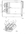
- the gas burner consists of the nozzle block 28 made of ceramic material, which is preferably corrugated in one direction (FIG.
- Main nozzles 29 are provided next to one another on the wave crests 33, while the secondary nozzles 30 are provided for the pilot flames in the wave troughs 34.
- the nozzles 29 and 30 are connected to the gas / air mixing space 8. They are designed such that they form a short-flame, continuous flame carpet 31 when the flames are burning.
- Four radial fans 12, 13 are provided symmetrically on its long sides. The high internal turbulence and the often reversed direction of rotation of the blower or blower or the changed air flow, for example in a two-minute cycle, ensure an astonishingly uniform temperature field of the baking air in the oven.
- the fan guide plates 36 which are designed as cylindrical half-shells, serve the same purpose, while the impellers of the radial fans are equipped with radial blades, so that their characteristics are independent of the direction of rotation.
- the electrically heated oven 41 (FIGS. 5, 6) has a foldable front wall 42 and two side walls 43 and 44 and a rear wall 45 a floor 46 covered. The cover is not shown.
- the walls with the bottom and the intermediate wall 61 define a baking space 47 in the main part, which lies in front.
- Electrical heating elements 48 are fastened to the rear wall 45.
- the spiral heating elements are symmetrical to four motors 49 and 50. It is possible to provide only two or six or an odd number of such motors, which are arranged symmetrically to the furnace meridian plane.
- Motors 49 and 50 drive radial blower rotors 52 and 53 with blower baffles 76, which, however, can in principle also be replaced by cross-flow blowers.
- the path that the hot air flowing through the heating rods 48 takes is indicated by arrows 57.
- the hot air flow 17 is sucked in by the radial fan blades 52, 53 through the suction openings 62.
- Fig. 7 shows an embodiment with only one air blower.
- the high internal turbulence and the often, e.g. in a two-minute cycle, the direction of rotation of the blower or blower or the changed air flow is reversed for an astonishingly uniform temperature field of the baking air in the oven.
- the fan baffles 76 which are designed as cylindrical half-shells, also support a turbulent and thus temperature-constant flow in the entire baking chamber 47 that is as uniform as possible.
- the impellers of the radial blowers are equipped with radial blades, so that their characteristics are independent of the direction of rotation.
- baffles installed in the baking chamber to guide the warm air, usually slotted plates possible due to this symmetrical structure and thus makes it much easier to keep the inside of the oven clean.
- the circulated air volume of the blowers can also be adapted to the baked goods by means of appropriate control elements.
- a time relay which can be set manually, is used to achieve a uniform temperature and a uniformly turbulent flow, in order to reverse the direction of rotation of the motors and thus drive the fans in the opposite direction.
- a thermostat-controlled microprocessor can also take over these functions. This creates an almost uniform air temperature, which is advantageous for achieving an optimal baking result.
Landscapes
- Engineering & Computer Science (AREA)
- Chemical & Material Sciences (AREA)
- Combustion & Propulsion (AREA)
- Mechanical Engineering (AREA)
- General Engineering & Computer Science (AREA)
- Baking, Grill, Roasting (AREA)
- Furnace Details (AREA)
- Air Bags (AREA)
- General Preparation And Processing Of Foods (AREA)
- Control And Other Processes For Unpacking Of Materials (AREA)
Abstract
Description
- Die vorliegende Erfindung betrifft einen gas- oder elektrisch beheizten Umluftofen zum Garen von Lebensmitteln mit mindestens einem Gebläse.
- Bestehende derartige Umluftofen weisen den Nachteil auf, dass sie wärmetechnisch nicht optimal ausgebildet sind, insbesondere im Garraum nicht gleichmässige Temperaturverhältnisse aufweisen, und/oder dass sie im Betrieb, infolge der Umluftgebläse, lärmig sind. Dabei sind sowohl elektrische, als auch gasbeheizte Umluftofen diesbezüglich verbesserungsbedürftig.
- Die vorliegende Aufgabe bezweckt die Schaffung eines Umluftofens, welcher diese Nachteile nicht aufweist, und der sowohl bezüglich Gargleichmässigkeit als auch Luftdurchmischung und Wärmeausnutzung optimale Bedingungen schaffen kann.
- Ein derartiger Umluftofen ist dadurch gekennzeichnet, dass Schaltmittel angeordnet sind, um die Drehrichtung des Gebläses, bei mehreren Gebläsen z.B. individuell, zu ändern.
- Ein Ausführungsbeispiel des Erfindungsgegenstandes wird anschliessend anhand einer rein schematischen Zeichnung erläutert.
- Es zeigen:
- Fig. 1 einen Horizontalschnitt durch einen Umluftofen der gasbeheizten Bauart mit einer geraden Anzahl von Umluftgebläsen, nach der Schnittlinie I - I der Fig. 2,
- Fig. 2 einen Schnitt durch den Ofen nach Fig. l, gemäss Schnittlinie II - II,
- Fig. 3 einen Schnitt durch den Ofen nach Schnittlinie III - III der Fig. 2,
- Fig. 4 eine persepektivische Darstellung eines Ausschnittes aus dem Gasbrenner-Mischraum mit einem in zwei Richtungen gewellten, keramischen Düsenblock mit Haupt- und Pilotdüsen sowie dem stilisiert dargestellten Flammenteppich.
- Fig. 5 einen Horizontalschnitt durch einen Umluftofen der elektrischen Bauart mit einer geraden Anzahl von Umluftgebläsen, nach der Schnittlinie V - V der Fig. 6,
- Fig. 6 einen Schnitt durch den Ofen nach Fig.,5, gemäss Schnittlinie VI - VI,
- Fig. 7 einen Horizontalschnitt durch einen Umluftofen der elektrischen Bauart mit einem Umluftgebläse analog Fig. 5.
- Der Backofen 1 weist eine klappbare Vorderwand 2 sowie zwei Seitenwände 3 und 4 auf und eine Rückwand 5. Unten ist er mittels eines Bodens 6 abgedeckt. Die Abdeckung ist nicht dargestellt. Die Wände mit-dem Boden legen im Hauptteil, welcher vorne liegt, einen Backraum 7 fest. An der Rückwand 5 ist ein Gasbrennermischraum 8 mit einer Gaszufuhrleitung 11 vorgesehen. Daneben liegen vier symmetrisch dazu angeordnete Motoren 9 und 10. Es ist möglich, nur einen, zwei oder mehr derartige Motoren, welche symmetrisch zur Ofenmeridianebene angeordnet sind, vorzusehen. Die Motoren 9 und 10 treiben Radialgebläseläufer 12 und 13 mit Gebläsegehäusen 36 an, die aber grundsätzlich auch durch Querstromgebläse ersetzt werden können. Unmittelbar gegenüber einem Düsenblock 28 liegt ein Wärmetauscher in Form einer Strahlungs-, Konvektions- und Leitwand 15.. Der Weg, den die aus dem Düsenblock 28 ausströmendenVerbrennungsgase nehmen, ist mittels Pfeilen 17 gekennzeichnet. Die Wand 15 legt, zusammen mit entsprechenden Leitblechen 21, an den beiden Seiten der Strahlungs-und Leitwand 15, eine Austrittsdüse 19 fest, welche den Abgasstrom gegen die Ansaugöffnungen der Gebläseläufer 12, 13, und in den Strom der Umluft leitet, der durch einen Umluftkanal 22 eintritt.
- Die Leitbleche 21 legen einen Ansaug/Mischraum 24 fest, der sicherstellt, dass die beiden Gebläse nicht die heissen Verbrennungsgase direkt, sondern eine Mischung von Luft mit einer Temperatur von normalerweise bis zu 300°C ansaugen. Die Gebläse, zusammen mit den Kammerwänden und den übrigen Einbauten, bewirken eine hohe Turbulenz der zirkulierenden Backluft, deren Folge ein annähernd gleichmässiges Temperaturfeld im Ofen bewirkt. Wie aus den Fig. 1 und 2 hervorgeht, handelt es sich, und dies ist ein wichtiger Punkt zur vorliegenden Erfindung, im Falle des gasbeheizten Gerätes um eine flächenartige Strahlungs-Heizquelle zum Erhitzen der Luft. Der Gasbrenner besteht aus dem Düsenblock 28 aus keramischem Material, welcher vorzugsweise in einer Richtung (Fig. 2) oder in zwei zueinander rechtwinkligen Richtungen (Fig. 4) gewellt ist, so dass Wellenberge 33 und Wellentäler 34 entstehen. Auf den Wellenbergen 33 sind nebeneinanderliegend Hauptdüsen 29 vorgesehen, während in den Wellentälern 34 die Nebendüsen 30 für die Pilotflammen vorgesehen sind. Die Düsen 29 und 30 stehen in Verbindung mit dem Gas-/Luft-Mischraum 8. Sie sind so ausgebildet, dass sie bei brennenden Flammen einen kurzflammigen, zusammenhängenden Flammenteppich 31 bilden. Auf dessen Längsseiten sind symmetrisch vier Radialgebläse 12, 13 vorgesehen. Die hohe innere Turbulenz und die oft, z.B. im Zweiminuten-Zyklus reversierte Drehrichtung des Gebläses bzw. der Gebläse bzw. der geänderten Luftströmung sorgen für ein erstaunlich gleichmässiges Temperaturfeld der Backluft im Ofen. Durch diese bezüglich Ofenmeridianebene symmetrische Ausbildung wird eine möglichst gleichmässige und damit temperaturkonstante Strömung im ganzen Backraum 7 erzeugt. Dem gleichen Zwecke dienen die Gebläseleitbleche 36, welche als zylindrische Halbschalen ausgebildet sind, während die Laufräder der Radialgebläse mit radialen Schaufeln ausgerüstet sind, so dass deren Charakteristik unabhängig von der Laufrichtung ist.
- Der elektrisch beheizte Backofen 41 (Fig. 5, 6) weist eine klappbare Vorderwand 42 sowie zwei Seitenwände 43 und 44 auf und eine Rückwand 45. Unten ist er mittels eines Bodens 46 abgedeckt. Die Abdeckung ist nicht dargestellt. Die Wände mit dem Boden und der Zwischenwand 61 legen im Hauptteil, welcher vorne liegt, einen Backraum 47 fest. An der Rückwand 45 sind elektrische Heizstäbe 48 befestigt. Die gewundenen Heizstäbe liegen symmetrisch zu vier Motoren 49 und 50. Es ist möglich, nur zwei oder sechs oder eine ungerade Anzahl derartiger Motoren, welche symmetrisch zur Ofenmeridianebene angeordnet sind, vorzusehen. Die Motoren 49 und 50 treiben Radialgebläseläufer 52 und' 53 mit Gebläseleitblechen 76 an, die aber grundsätzlich auch durch Querstromgebläse ersetzt werden können. Der Weg, den die die Heizstäbe 48 durchströmende Heissluft nimmt, ist mittels Pfeilen 57 gekennzeichnet. Der Heissluftstrom 17 wird von den Radialgebläselaufern 52, 53 durch die Ansaugöffnungen 62 angesaugt.
- Fig. 7 zeigt eine Ausführung mit nur einem Umluftgebläse. Auch hier sorgen die hohe innere Turbulenz und die oft, z.B. im Zweiminuten-Zyklus reversierte Drehrichtung des Gebläses bzw. der Gebläse bzw. der geänderten Luftströmung für ein erstaunlich gleichmässiges Temperaturfeld der Backluft im Ofen.
- Auch durch die Gebläseleitbleche 76, welche als zylindrische Halbschalen ausgebildet sind, wird eine möglichst gleichmässige turbulente und damit temperaturkonstante Strömung im ganzen Backraum 47 unterstützt. Die Laufräder der Radialgebläse sind mit radialen Schaufeln ausgerüstet, so dass deren Charakteristik unabhängig von der Laufrichtung ist.
- Der Verzicht auf im Backraum eingebaute Leitbleche zur Leitung der Warmluft, normalerweise Schlitzbleche, ist durch diesen symmetrischen Aufbau möglich und gestattet dadurch das Reinhalten des Backofeninnern wesentlich einfacher. Durch entsprechende Regelorgane kann auch die umgewälzte Luftmenge der Gebläse dem Backgut angepasst werden.
- Aus sicherheitstechnischen Gründen ist bei der Gasausführung über dem Flächenbrenner eine Explosionsklappe vorgesehen, um die Zerstörung von Backofenteilen zu verhüten. Zur Erreichung einer gleichmässigen Temperatur und einer gleichmässig turbulenten Strömung dient ein Zeitrelais, das von Hand einstellbar ist, um die Drehrichtung der Motoren zu reversieren und damit die Gebläse im Gegendrehsinn anzutreiben. Es kann auch ein thermostatgesteuerter Mikroprozessor diese Funktionen übernehmen. Damit wird eine annähernd gleichmässige Lufttemperatur erzeugt, was zur Erreichung eines optimalen Backergebnisses von Vorteil ist. Diese Drehrichtungsänderungen der Gebläse - es kann auch eine Drehrichtungskombination von links- und rechtsdrehenden Gebläsen sein - werden vorzugsweise periodisch vorgenommen. Die Anwendung mehrerer kleinerer Gebläse reduziert die Lärmentwicklung stark. Auch eine gute Platzausnützung bei minimalen Aussenabmessungen und maximalem Nutzraum wird dadurch erreicht.
Claims (14)
Priority Applications (1)
| Application Number | Priority Date | Filing Date | Title |
|---|---|---|---|
| AT81104950T ATE9179T1 (de) | 1980-07-11 | 1981-06-26 | Gas- oder elektrisch beheizter umluftofen zum garen von lebensmitteln. |
Applications Claiming Priority (4)
| Application Number | Priority Date | Filing Date | Title |
|---|---|---|---|
| CH5329/80 | 1980-07-11 | ||
| CH532980 | 1980-07-11 | ||
| CH3920/81 | 1981-06-15 | ||
| CH392081 | 1981-06-15 |
Publications (3)
| Publication Number | Publication Date |
|---|---|
| EP0043959A2 true EP0043959A2 (de) | 1982-01-20 |
| EP0043959A3 EP0043959A3 (en) | 1982-03-31 |
| EP0043959B1 EP0043959B1 (de) | 1984-08-29 |
Family
ID=25694171
Family Applications (1)
| Application Number | Title | Priority Date | Filing Date |
|---|---|---|---|
| EP81104950A Expired EP0043959B1 (de) | 1980-07-11 | 1981-06-26 | Gas- oder elektrisch beheizter Umluftofen zum Garen von Lebensmitteln |
Country Status (8)
| Country | Link |
|---|---|
| US (1) | US4467777A (de) |
| EP (1) | EP0043959B1 (de) |
| DE (1) | DE3165770D1 (de) |
| DK (1) | DK301281A (de) |
| ES (1) | ES8203564A1 (de) |
| FR (1) | FR2486631A1 (de) |
| GR (1) | GR74358B (de) |
| NO (1) | NO155463C (de) |
Cited By (2)
| Publication number | Priority date | Publication date | Assignee | Title |
|---|---|---|---|---|
| EP0528593A1 (de) * | 1991-08-15 | 1993-02-24 | Heat And Control, Inc. | Ofen zur Behandlung von Nahrungsmitteln mit Prozessdampf |
| EP3425286A1 (de) * | 2017-07-07 | 2019-01-09 | Vestel Beyaz Esya Sanayi Ve Ticaret A.S. | Kochvorrichtung und betriebsverfahren dafür |
Families Citing this family (31)
| Publication number | Priority date | Publication date | Assignee | Title |
|---|---|---|---|---|
| US4671250A (en) * | 1986-07-28 | 1987-06-09 | Thermo Electron Corporation | Direct-firing gas convection oven |
| US5403607A (en) * | 1987-02-17 | 1995-04-04 | American Harvest, Inc. | Method for rapidly cooking food |
| US4817509A (en) * | 1987-02-17 | 1989-04-04 | Alternative Pioneering Systems Inc. | Air Fryer |
| AT403734B (de) * | 1987-04-01 | 1998-05-25 | Vanicek Friedrich | Anordnung von axialventilatoren für holztrocknungsanlagen |
| US4920948A (en) * | 1987-10-29 | 1990-05-01 | Micro-Technology Licensing Corporation | Parameter control system for an oven |
| US4867132A (en) * | 1988-11-23 | 1989-09-19 | Garland Commercial Industries, Inc. | Gas fired convection oven with improved air delivery and heat exchange structure |
| US5222474A (en) * | 1989-11-14 | 1993-06-29 | Garland Commercial Industries, Inc. | Convection cooking oven with enhanced temperature distribution uniformity |
| US5121737A (en) * | 1989-11-14 | 1992-06-16 | Garland Commercial Industries, Inc. | Convection cooking oven with enhanced temperature distribution uniformity |
| US5466912A (en) * | 1993-04-13 | 1995-11-14 | American Harvest, Inc. | Convection oven |
| US6140626A (en) * | 1998-04-23 | 2000-10-31 | Turbochef Technologies, Inc. | System for rapid air temperature modification in a recycling oven |
| KR100388274B1 (ko) * | 1999-12-11 | 2003-06-27 | 주식회사 엘지이아이 | 전자레인지의 대류팬제어방법 |
| US6805112B2 (en) * | 2001-06-27 | 2004-10-19 | James T. Cole | Convection oven having multiple airflow patterns |
| US6730880B2 (en) * | 2002-02-05 | 2004-05-04 | General Electric Company | Oven and methods for operating same |
| US6727478B2 (en) * | 2002-02-05 | 2004-04-27 | General Electric Company | Multi rack oven and methods for operating same |
| CN1691890B (zh) * | 2002-07-10 | 2010-11-03 | 杜克制造公司 | 食物加热装置和方法 |
| US7105779B2 (en) * | 2002-07-10 | 2006-09-12 | Duke Manufacturing Company | Food warming apparatus and method |
| US6943321B2 (en) * | 2002-08-30 | 2005-09-13 | Wolf Appliance Company, Llc | Convection oven with forced airflow circulation zones |
| US8242413B2 (en) * | 2006-11-29 | 2012-08-14 | Lg Electronics Inc. | Method of controlling oven |
| AU2007347943B2 (en) * | 2007-01-17 | 2011-02-24 | Lg Electronics Inc. | Oven |
| WO2009097340A2 (en) | 2008-01-28 | 2009-08-06 | Duke Manufacturing Co. | Convection oven |
| US8138452B2 (en) * | 2008-07-14 | 2012-03-20 | Whirlpool Corporation | Convection oven |
| US8350192B2 (en) * | 2008-07-18 | 2013-01-08 | Electrolux Home Products, Inc. | Dual fan convection performance divider |
| US8097833B2 (en) * | 2008-12-16 | 2012-01-17 | Whirlpool Corporation | Convection cooking in multi-fan convection oven |
| US8258435B2 (en) * | 2008-12-16 | 2012-09-04 | Whirlpool Corporation | Dual fan convection oven |
| US8304695B2 (en) * | 2008-12-16 | 2012-11-06 | Whirlpool Corporation | Priority controlled multi-fan convection oven |
| DE102010037284A1 (de) | 2010-09-02 | 2012-03-08 | Rational Ag | Verfahren zur Durchführung eines Garprozesses |
| EP3367857B1 (de) | 2015-10-30 | 2019-05-29 | Koninklijke Philips N.V. | Vorrichtung und verfahren zur herstellung von lebensmittelzutaten mit heissluft und darin eingeführter flüssigkeit |
| WO2017214129A1 (en) * | 2016-06-06 | 2017-12-14 | Alto-Shaam, Inc. | Food service oven with multipoint temperature monitoring |
| US11045047B2 (en) | 2017-11-10 | 2021-06-29 | Ron's Enterprises, Inc. | Variable capacity oven |
| WO2020088845A1 (en) * | 2018-10-30 | 2020-05-07 | Arcelik Anonim Sirketi | A cooking device for homogeneous cooking |
| CN114052521A (zh) * | 2020-07-27 | 2022-02-18 | 沙克忍者运营有限责任公司 | 台面烹饪系统 |
Citations (8)
| Publication number | Priority date | Publication date | Assignee | Title |
|---|---|---|---|---|
| DE2145094B2 (de) * | 1971-09-09 | 1974-10-10 | G. Bauknecht Gmbh, Elektrotechnische Fabriken, 7000 Stuttgart | |
| DE2346085A1 (de) * | 1973-09-13 | 1975-03-27 | Licentia Gmbh | Bratofen mit beheizung und einem geblaese |
| DE2519604B2 (de) * | 1974-05-18 | 1978-09-28 | Zanussi Grandi Impianti S.P.A., Pordenone (Italien) | Backofen mit direkter Beheizung durch einen Brenner und erzwungener Warmluftströmung |
| DE2834892A1 (de) * | 1977-08-09 | 1979-02-22 | Tennant & Sons Warrington Ltd | Gasbrenner |
| DE2739198A1 (de) * | 1977-08-31 | 1979-03-15 | Kueppersbusch | Geraet zum garen bzw. erhitzen von esswaren |
| DE7908555U1 (de) * | 1979-03-27 | 1979-06-28 | Fr. Winkler Kg, Spezialfabrik Fuer Baeckereimaschinen Und Backoefen, 7730 Villingen | Etagenbackofen mit strahlungsheizung und backraum-luftumwaelzung |
| EP0002784A1 (de) * | 1977-12-27 | 1979-07-11 | Clarence W. West | Ofen mit wechselnder Luftströmung |
| JPS5525773A (en) * | 1978-08-14 | 1980-02-23 | Matsushita Electric Ind Co Ltd | Infrared radiant burner |
Family Cites Families (5)
| Publication number | Priority date | Publication date | Assignee | Title |
|---|---|---|---|---|
| US1923145A (en) * | 1931-01-28 | 1933-08-22 | Leeds & Northrup Co | Method and apparatus for heat treating |
| US3861378A (en) * | 1969-08-27 | 1975-01-21 | Lincoln Mfg Co | Reversible air flow oven |
| US3620520A (en) * | 1970-07-29 | 1971-11-16 | Sunbeam Equip | Furnace heating control system |
| DE2100818B2 (de) * | 1971-01-08 | 1973-05-03 | Vosswerke Gmbh, 3203 Sarstedt | Vorrichtung zum erwaermen, garen, braten und auftauen von speisen |
| US4029463A (en) * | 1973-01-26 | 1977-06-14 | Tipe Revent Ab | Method for baking food products |
-
1981
- 1981-06-26 EP EP81104950A patent/EP0043959B1/de not_active Expired
- 1981-06-26 GR GR65359A patent/GR74358B/el unknown
- 1981-06-26 DE DE8181104950T patent/DE3165770D1/de not_active Expired
- 1981-06-30 ES ES503573A patent/ES8203564A1/es not_active Expired
- 1981-07-08 DK DK301281A patent/DK301281A/da not_active Application Discontinuation
- 1981-07-10 NO NO812370A patent/NO155463C/no unknown
- 1981-07-15 FR FR8113769A patent/FR2486631A1/fr active Granted
-
1983
- 1983-08-12 US US06/522,511 patent/US4467777A/en not_active Expired - Fee Related
Patent Citations (8)
| Publication number | Priority date | Publication date | Assignee | Title |
|---|---|---|---|---|
| DE2145094B2 (de) * | 1971-09-09 | 1974-10-10 | G. Bauknecht Gmbh, Elektrotechnische Fabriken, 7000 Stuttgart | |
| DE2346085A1 (de) * | 1973-09-13 | 1975-03-27 | Licentia Gmbh | Bratofen mit beheizung und einem geblaese |
| DE2519604B2 (de) * | 1974-05-18 | 1978-09-28 | Zanussi Grandi Impianti S.P.A., Pordenone (Italien) | Backofen mit direkter Beheizung durch einen Brenner und erzwungener Warmluftströmung |
| DE2834892A1 (de) * | 1977-08-09 | 1979-02-22 | Tennant & Sons Warrington Ltd | Gasbrenner |
| DE2739198A1 (de) * | 1977-08-31 | 1979-03-15 | Kueppersbusch | Geraet zum garen bzw. erhitzen von esswaren |
| EP0002784A1 (de) * | 1977-12-27 | 1979-07-11 | Clarence W. West | Ofen mit wechselnder Luftströmung |
| JPS5525773A (en) * | 1978-08-14 | 1980-02-23 | Matsushita Electric Ind Co Ltd | Infrared radiant burner |
| DE7908555U1 (de) * | 1979-03-27 | 1979-06-28 | Fr. Winkler Kg, Spezialfabrik Fuer Baeckereimaschinen Und Backoefen, 7730 Villingen | Etagenbackofen mit strahlungsheizung und backraum-luftumwaelzung |
Non-Patent Citations (1)
| Title |
|---|
| Patents Abstracts of Japan Band 4, Nr. 60, 06. Mai 1980 Seite 60M10 * |
Cited By (2)
| Publication number | Priority date | Publication date | Assignee | Title |
|---|---|---|---|---|
| EP0528593A1 (de) * | 1991-08-15 | 1993-02-24 | Heat And Control, Inc. | Ofen zur Behandlung von Nahrungsmitteln mit Prozessdampf |
| EP3425286A1 (de) * | 2017-07-07 | 2019-01-09 | Vestel Beyaz Esya Sanayi Ve Ticaret A.S. | Kochvorrichtung und betriebsverfahren dafür |
Also Published As
| Publication number | Publication date |
|---|---|
| ES503573A0 (es) | 1982-04-16 |
| NO155463B (no) | 1986-12-22 |
| NO812370L (no) | 1982-01-12 |
| EP0043959A3 (en) | 1982-03-31 |
| US4467777A (en) | 1984-08-28 |
| GR74358B (de) | 1984-06-27 |
| FR2486631B1 (de) | 1984-03-30 |
| NO155463C (no) | 1987-04-01 |
| FR2486631A1 (fr) | 1982-01-15 |
| DE3165770D1 (en) | 1984-10-04 |
| ES8203564A1 (es) | 1982-04-16 |
| EP0043959B1 (de) | 1984-08-29 |
| DK301281A (da) | 1982-01-12 |
Similar Documents
| Publication | Publication Date | Title |
|---|---|---|
| EP0043959A2 (de) | Gas- oder elektrisch beheizter Umluftofen zum Garen von Lebensmitteln | |
| DE69637010T2 (de) | Luftverteiler für mikrowellenofen | |
| DE2825461C2 (de) | ||
| DE69200704T2 (de) | Gasbeheizter Ofen mit erzwungener Konvektion. | |
| DE2003530B2 (de) | Ofen mit einem Kochraum und einem Gebläse | |
| DE2115251A1 (de) | Gasherd | |
| DE2615604C3 (de) | Backofen, insbesondere mit Mitteln zur pyrolytischen Reinigung mit einem Kühlluftgebläse | |
| DE3031041A1 (de) | Gas- oder elektrisch beheizter umluftofen | |
| EP0641976A1 (de) | Elektrischer Back- und Bratofen | |
| DE2435138A1 (de) | Backofen | |
| EP0580940B1 (de) | Backofen | |
| DE3442812C1 (de) | Backofen mit einem Umluftgebläse | |
| DE2940300A1 (de) | Gaskochofen | |
| EP0215406A2 (de) | Backofen | |
| EP0954969A2 (de) | Heizregister mit Wirbelblechen | |
| EP0067806B1 (de) | Gasbeheizter Back-, Brat- und Grillofen | |
| EP0271783B1 (de) | Raumheizgerät für Kleinräume, insbesondere für fahrbare Räume | |
| DE60318940T2 (de) | Ofen zum garen von lebensmitteln | |
| EP0443330A2 (de) | Backofen | |
| DE3337162A1 (de) | Warmluftumwaelzofen fuer teig- und backwaren oder dgl. | |
| DE2657267A1 (de) | Ofen mit zwangsumlauf | |
| DE2928716C2 (de) | ||
| DE3049922C2 (de) | Mikrowellen-kochherd | |
| DE2167022A1 (de) | Haushaltbackofen | |
| DE2158557C3 (de) | Brennerbefeuerte Heißluft-Backvorrichtung mit einem Gebläse |
Legal Events
| Date | Code | Title | Description |
|---|---|---|---|
| PUAI | Public reference made under article 153(3) epc to a published international application that has entered the european phase |
Free format text: ORIGINAL CODE: 0009012 |
|
| AK | Designated contracting states |
Designated state(s): AT BE CH DE FR GB IT NL SE |
|
| PUAL | Search report despatched |
Free format text: ORIGINAL CODE: 0009013 |
|
| 17P | Request for examination filed |
Effective date: 19811205 |
|
| AK | Designated contracting states |
Designated state(s): AT BE CH DE FR GB IT NL SE |
|
| ITF | It: translation for a ep patent filed | ||
| GRAA | (expected) grant |
Free format text: ORIGINAL CODE: 0009210 |
|
| AK | Designated contracting states |
Designated state(s): AT BE CH DE FR GB IT LI NL SE |
|
| REF | Corresponds to: |
Ref document number: 9179 Country of ref document: AT Date of ref document: 19840915 Kind code of ref document: T |
|
| REF | Corresponds to: |
Ref document number: 3165770 Country of ref document: DE Date of ref document: 19841004 |
|
| ET | Fr: translation filed | ||
| PLBE | No opposition filed within time limit |
Free format text: ORIGINAL CODE: 0009261 |
|
| STAA | Information on the status of an ep patent application or granted ep patent |
Free format text: STATUS: NO OPPOSITION FILED WITHIN TIME LIMIT |
|
| 26N | No opposition filed | ||
| PGFP | Annual fee paid to national office [announced via postgrant information from national office to epo] |
Ref country code: FR Payment date: 19890426 Year of fee payment: 9 |
|
| PGFP | Annual fee paid to national office [announced via postgrant information from national office to epo] |
Ref country code: BE Payment date: 19890518 Year of fee payment: 9 |
|
| PGFP | Annual fee paid to national office [announced via postgrant information from national office to epo] |
Ref country code: SE Payment date: 19890522 Year of fee payment: 9 |
|
| PGFP | Annual fee paid to national office [announced via postgrant information from national office to epo] |
Ref country code: AT Payment date: 19890627 Year of fee payment: 9 |
|
| ITTA | It: last paid annual fee | ||
| PGFP | Annual fee paid to national office [announced via postgrant information from national office to epo] |
Ref country code: NL Payment date: 19890630 Year of fee payment: 9 Ref country code: GB Payment date: 19890630 Year of fee payment: 9 |
|
| PGFP | Annual fee paid to national office [announced via postgrant information from national office to epo] |
Ref country code: DE Payment date: 19890715 Year of fee payment: 9 |
|
| PGFP | Annual fee paid to national office [announced via postgrant information from national office to epo] |
Ref country code: CH Payment date: 19890830 Year of fee payment: 9 |
|
| PG25 | Lapsed in a contracting state [announced via postgrant information from national office to epo] |
Ref country code: GB Effective date: 19900626 Ref country code: AT Effective date: 19900626 |
|
| PG25 | Lapsed in a contracting state [announced via postgrant information from national office to epo] |
Ref country code: SE Effective date: 19900627 |
|
| PG25 | Lapsed in a contracting state [announced via postgrant information from national office to epo] |
Ref country code: LI Effective date: 19900630 Ref country code: CH Effective date: 19900630 Ref country code: BE Effective date: 19900630 |
|
| BERE | Be: lapsed |
Owner name: NIRO PLAN A.G. Effective date: 19900630 |
|
| PG25 | Lapsed in a contracting state [announced via postgrant information from national office to epo] |
Ref country code: NL Effective date: 19910101 |
|
| NLV4 | Nl: lapsed or anulled due to non-payment of the annual fee | ||
| GBPC | Gb: european patent ceased through non-payment of renewal fee | ||
| PG25 | Lapsed in a contracting state [announced via postgrant information from national office to epo] |
Ref country code: FR Effective date: 19910228 |
|
| REG | Reference to a national code |
Ref country code: CH Ref legal event code: PL |
|
| PG25 | Lapsed in a contracting state [announced via postgrant information from national office to epo] |
Ref country code: DE Effective date: 19910301 |
|
| REG | Reference to a national code |
Ref country code: FR Ref legal event code: ST |
|
| EUG | Se: european patent has lapsed |
Ref document number: 81104950.1 Effective date: 19910206 |