EP0033131B1 - Dispositif déclanchable de blocage sous tension - Google Patents
Dispositif déclanchable de blocage sous tension Download PDFInfo
- Publication number
- EP0033131B1 EP0033131B1 EP81100425A EP81100425A EP0033131B1 EP 0033131 B1 EP0033131 B1 EP 0033131B1 EP 81100425 A EP81100425 A EP 81100425A EP 81100425 A EP81100425 A EP 81100425A EP 0033131 B1 EP0033131 B1 EP 0033131B1
- Authority
- EP
- European Patent Office
- Prior art keywords
- spring plunger
- housing
- bearing according
- ski
- pressure
- Prior art date
- Legal status (The legal status is an assumption and is not a legal conclusion. Google has not performed a legal analysis and makes no representation as to the accuracy of the status listed.)
- Expired
Links
Images


Classifications
-
- A—HUMAN NECESSITIES
- A63—SPORTS; GAMES; AMUSEMENTS
- A63C—SKATES; SKIS; ROLLER SKATES; DESIGN OR LAYOUT OF COURTS, RINKS OR THE LIKE
- A63C9/00—Ski bindings
- A63C9/08—Ski bindings yieldable or self-releasing in the event of an accident, i.e. safety bindings
- A63C9/088—Ski bindings yieldable or self-releasing in the event of an accident, i.e. safety bindings with electronically controlled locking devices
Definitions
- the invention relates to a releasable clamping bearing, in particular for ski bindings, which has a displaceable spring piston under the force of a compression spring as a holding element, the rear end of the spring piston being supported against an abutment.
- a telescopic spring piston is known as a resilient clamping abutment.
- the rear area of the telescopic spring piston is rigidly fixed in the binding housing.
- no indications of an electrical and / or electronic triggering of the ski binding can be found.
- the present invention is based on the object of providing a releasable clamping bearing, in particular for ski bindings, in which a predetermined clamping pressure for holding the object in the clamping device is not substantially exceeded in order not to damage or destroy the clamped object.
- the predetermined clamping pressure should be easy to set and vary, the predetermined clamping pressure being dependent both on the clamped object, the material from which it is made and the measures to which the clamped object is subjected.
- such a device should be easily readjustable with regard to the clamping pressure if the dimensioning of the clamped object changes in the clamping direction for certain reasons, for example due to shrinkage of plastic material when the temperature drops.
- the adjustment of the clamping pressure should be possible quickly and easily; at the same time, if the clamping pressure is exceeded beyond a defined value, the clamping pressure is lifted and thus the clamped object is released immediately and reliably.
- the releasable clamping bearing in particular for ski bindings, which has a displaceable spring piston under the force of a compression spring as a holding element, the rear end of the spring piston being supported against an abutment, in that the spring piston consists of a front, the Shoe-facing part and a rear part, which are telescopically displaceable against each other against the force of the compression spring, and that sensors provide a signal when the two parts are displaced and by a predetermined amount, which causes the abutment to be unlocked.
- the object to be clamped is clamped between two clamping bearings which hold the object between them in punctiform or planar fashion.
- a bearing which can be designed to be resilient, for example, has a device for adjusting the clamping pressure with which the counter-clamp is clamped.
- This device for pressure adjustment preferably serves at the same time as an indication of the clamping pressure actually acting on the clamped object.
- Clamping pressure set The release pressure at which the clamping pressure is to be released is measured in the spring-loaded clamping bearing by pressure sensors or light barriers known per se or the like; When the set limit of the clamping pressure is reached, these electronically generate a signal that triggers the release of the clamping pressure, so that the clamped object is released.
- a clamping bearing is designed such that it can be moved mechanically, for example by means of an adjusting screw, in the direction of the movable, spring-shaped clamping bearing. It is hereby achieved that when the length of the clamped object is shortened in the clamping direction, the predetermined clamping pressure is set to the opposite bearing by corresponding movement of this clamping bearing. The triggering of the mechanism for canceling the clamping pressure when the predetermined and set limit value of the clamping pressure is reached is carried out in the manner described.
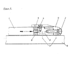
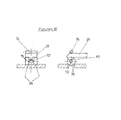
- the object 1 to be clamped is a ski boot;
- the front, adjustable holding device for the tip of the ski shoe consists of a block 9 which is fixedly arranged on the ski 6 and in which an adjusting screw 2 is arranged for the adjustment.
- the adjusting screw 2 acts on a slider 3 depending on the direction of rotation of the adjusting screw 2 in the direction of the automatic heel unit or is moved in the opposite direction.
- the tip of the ski shoe is held by the component 5, which is arranged on the slide 3 so that it can be adjusted in height by the screw 4.
- Centering rollers, bolts and / or clamp-like components known per se are provided for laterally holding the tip of the ski shoe sideways.
- the construction described makes it possible to move the ski boot in the direction of the longitudinal axis of the ski as required by adjusting the set screw 2 and correspondingly displacing the slide 3.
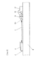
- the embodiment according to the invention is shown schematically as a ski binding in FIG.
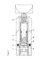
- the housing 13 of the automatic heel unit is arranged on the ski 6 in the rear region of the ski, in which a spring piston 18, consisting of the front 18a and rear spring piston parts 18b, is arranged in a spring piston housing.
- the pressure exerted on the spring piston 18a + b by adjusting the adjusting screw 2 via the ski boot 1 is indicated by the position of the lever 15: this lever is arranged on an axis 16 which is at an angle of approximately 90 with the spring piston 18 ° forms, and is driven by this directly over matched profiles; this results in a pivoting of the lever 15 depending on the load on the spring piston part 18a, z. B.
- the clamping pressure for the ski shoe which is to be determined in the usual way, is set at + 20 ° C, this clamping pressure can be read off by means of the marking in area 16: If the length of the ski shoe 1 is reduced to -10 ° C, for example, by cooling, it is adjusted the set screw 2 of the ski boot 1 so far in the direction of the automatic heel unit 13 until the same marking setting is reached again, so that the predetermined clamping pressure is set.
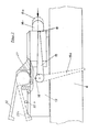
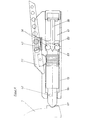
- FIG. 3 shows an automatic heel unit according to FIG. 2 in a side view; here, in a manner known per se, an operating lever 22 is added, which is connected to the spring piston part 18a in the upper region of the housing 13 via a correspondingly adapted profile; Before the ski boot is clamped in, the system is in a relaxed position, i.e. the spring piston is in the dashed position, the pointer lever in position 15a and the operating lever in position 22a; in the tensioned state, the spring piston assumes the rear position (solid line), the pointer lever occupies position 15 and the operating lever occupies position 22. Otherwise, the reference numbers correspond to those according to FIG. 2.
- the predetermined clamping pressure can be set again by adjusting the adjusting screw 2 according to FIG. 1 by bringing the markings 16 into line. Otherwise, the reference numbers have the meaning given above.
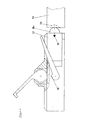
- the automatic heel unit according to the invention is shown schematically in section parallel to the ski surface.
- the spring piston 18 is telescopic, the two parts 18a + b of the telescopic spring piston 18 being supported against one another by a spring 36.
- At least one pin 34a serves as a safeguard against the rotation of the Spring piston 18.
- the spring piston 18a has a step-shaped stop 35, which prevents the spring piston 18a from coming out of the housing 13 by a certain amount.
- stop pins, rollers or balls 38 are arranged in the housing 13, which block the escape of the rear part 18b of the telescopic spring bolt 18, the axis of these locking rollers 38 being guided in lateral, vertical link slots in the rear spring piston region.
- a bolt 39 Arranged in the end region of the housing 13 is a bolt 39 which can be displaced in the direction of the longitudinal axis of the ski and which has a cylindrical recess in which the cylindrical rear region 18b of the spring piston 18 can be received; when the bolt 39 moves towards the ski tip, the locking by the balls or rollers 38 is lifted by external ramps on the locking bolt 39, so that the rear region 18b of the telescopic spring bolt 18 can enter the recess in the bolt 39, as a result of which the pressure of the Spring piston part 18b is practically canceled on the ski boot heel.
- sensors 42 are arranged for electronic pressure absorption.
- Piezo elements are preferably used here which generate a certain voltage at a certain pressure, which unlocks the unlocking of the locking elements 38 by electromagnetic movement of the latch 39 in the direction of the ski tip at a certain limit value which corresponds to the previously set trigger pressure.
- the pressure sensors instead of the pressure sensors, light barriers or the like can also be used. are used, which register the displacement of the spring piston 18 into the housing 13 with increasing pressure on the spring piston 18 in a manner known per se and, when a certain piston path is exceeded, which is proportional to the pressure increase, the unlocking of the piston 18 within the housing 13 and thus causing the relaxation of the spring element 36.
- the unlocking mechanism consists of the bolt or slide 39, which is connected to an armature 40, which in turn passes through a coil 41.
- a magnetic field is generated in the magnet coil 41, by means of which the armature 40 sets the slide 39 in the direction of the ski tip and thus unlocks the piston 18 and the spring 36 is relaxed.
- the electromagnetic electronic part of the device is. powered by commercially available electric batteries 43.
- the control works in such a way that the signals from the pressure sensors or light barriers 42 enter the respective values into a converter.
- the converter can be preprogrammed to certain values by microswitches 44. If necessary, the converter can also be preprogrammed using a continuously adjustable resistor.
- FIG. 6 shows the automatic heel unit according to the invention in accordance with FIG. 5 in a different functional state. While in FIG. 5 the rear part 18b of the telescopic spring piston 18 is shown in the locked position, in FIG. 6 this part 18b has entered the recess provided in the slide or bolt 39; the lock was previously unlocked by the rollers 38 by moving the bolt or slide 39 in the direction of the ski tip, the rollers being pressed back into their bearings by the run-up profiles on the slide 39 in the region of the rollers. The described forward movement of the slide 39 was triggered and brought about, for example, by a pressure exerted sideways on the tip of the spring piston part 18a beyond the set limit value in the manner described.
- the pressure sensors are preferably arranged as semiconductors, measuring strips or piezo elements on the piston or on the adjacent housing 13 and generate a certain voltage when the spring piston 18 acts on pressure.
- this voltage is divided via the voltage distributors R1 and R2.
- the voltage required for the trigger value is preferably sampled at R2.
- the same acts on a threshold switch V1, which transmits a pulse to a switching amplifier V2 when a certain input voltage is reached.
- This excites a coil L1 (coil 41 according to FIGS. 5 and 6), which builds up a magnetic field through which the armature 40 is moved with the slide 39 (according to FIGS. 5 and 6), whereby the spring piston 18 is unlocked.
- Resistor R2 can be changed using a potentiometer or a microswitch, which optionally connects several resistors in parallel. This allows the voltage to be set at a given pressure.
- the threshold switch is a circuit which is known per se as a signal converter.
- the slider 39 (FIGS. 5 and 6) is reset outside the electronic control by a return spring, which is designated 45 in FIG. 5, for example.
- a limit switch 22b (FIG. 3) is provided, which is automatically switched to position 22a (FIG. 3) by the opening lever in the idle state of the tensioning device. If a pressure of approximately 50% of the trigger pressure acts in the direction of the longitudinal axis of the spring on the spring piston 18, the opening lever 22 is raised to such an extent that the spring-mounted switch 22b is released and the circuit is closed.
- the pointer or lever 15 according to FIGS. 2 and 3, which, in cooperation with corresponding markings on the housing 13, serves as an indication of the pressure acting on the spring piston 18, can preferably be designed as a ski brake.
- the axis about which the component 15 rotates is not parallel to the ski surface, but arranged at an angle of about 40 to 50 °, preferably 45 °; it is hereby achieved that in the tensioned state of the spring 36, the pointer 15 designed as a brake arm pivots over the width of the ski and thus does not protrude sideways beyond the ski.
- a second pointer 15 designed as a brake arm can be arranged on the opposite side of the housing 13.
- FIGS. 8 schematically shows another unlocking mechanism of the automatic heel unit, which otherwise corresponds to the automatic heel unit according to FIGS. 5 and 6.
- the rear part 18b of the telescopic spring piston 18 is locked by means of spherical or roller-like locking elements 38 which are arranged opposite one another within this area.
- the locking elements 38 suspended in the piston part 18b are pressed in a locking manner partly through corresponding openings in the wall of the spring piston part 18b into corresponding counter bearings or depressions in the adjacent housing wall, so that the rear part 18b of the spring piston 18 is locked with the housing 13.
- the locking elements 38 are held in the locking position by the bolt or slide 39 which enters the spring piston part 18b through the rear wall thereof and between the locking elements 38.
- the bolt or slide 39 is formed in one piece with the armature 40, which is arranged in the coil 41 and is set in motion in the manner described.
- the bar 39 which is rod-shaped in the present case, tapers in its front end, the corresponding side walls forming a profile 63, on which the locking elements 38 roll up or roll off when locking or unlocking.
- a spring element (not shown) is preferably arranged which, after unlocking and completely relieving the load on the front part of the spring piston 18a, returns its rear region 18b to the starting position for the locking.
- the bolt 39 or the armature 40 is preferably extended through the rear wall of the housing 13, so that on the one hand the locking can be carried out by hand and on the other hand it can be checked visually whether the spring piston 18 is locked or not.
- the housing 13 there is an assembly opening for the components of the automatic heel unit arranged in the interior, which can be closed by a screw cap 65. This ensures easy access to the interior of the automatic heel unit while at the same time excluding dirt and water. This also makes manipulation by third parties in binding binding difficult.
- FIG. 9 schematically shows a cross section through the area of an automatic heel unit according to the invention, in which the front part 18a of the spring piston emerges from the housing 13.
- the pressure is taken up by only one electrical semiconductor 84, to which the pressure which is exerted on the front part 18a of the spring piston by the ski boot 1 by twisting or the like of the ski boot 1 in the binding, via one, the front region of the spring piston a setting 83 that extends around 180 °.
- An adjustable screw 85 serves as a counterbearing for the pressure transducer 84.
- Two scenes are preferably arranged in a V-shape in the outlet opening of the spring piston from the housing, which surround the spring piston over a range of approximately 90 ° in each case, and which bear against a sheet-like pressure sensor.
- circular or semicircular sensors can also be used in analog applications.
- FIG. 10 shows a cross section in the left half of the figure and a longitudinal section in the right half through a locking mechanism according to the invention.
- the two locking rollers 38 and the intermediate guide roller 70 with a smaller diameter are rotatably mounted on a common axis 75.
- the axis 75 is arranged parallel to the ski surface and at right angles to the longitudinal axis of the ski in the rear region of the piston 18; the two ends of the axle 75 are slotted in the side walls of the rear part 18b of the piston; the slots extend in the direction perpendicular to the ski surface, so that the axis 75, the locking rollers 38 and the guide roller 70 are movably mounted in this direction.
- the bolt 39 has at its front end a control profile 63 on which the guide roller 70 rests.
- a bearing roller 74 serves as the counter bearing for the bolt 39, so that the bolt 39 is mounted between the bearing roller 74 and the guide roller 70;
- the control profile is designed in such a way that when the bolt 39 moves in the direction of the longitudinal axis of the ski, the axis 75 with the locking rollers 38 is pressed in a locking manner via corresponding guidance of the guide roller 70 on the control profile through the corresponding openings in the piston and housing wall: see FIG. 10 , right half; in the opposite movement of the bolt 39 is unlocked.
- FIG. 11 A further unlocking and locking mechanism of another embodiment of the device according to the invention is shown schematically in FIG. 11.
- this control profile is applied to a separate component 95 which can be moved in the rear part 18b of the spring piston in the longitudinal direction of the automatic heel unit is arranged.
- This component 95 which in principle holds the locking element or elements 38 in the locking position in the same way as in FIG. 8, is moved from the locking position into the unlocking position when the trigger signal is generated by the bolt 39 or armature 40 which is bolt-shaped in the present case Knocked out in the direction of the ski tip; 94 denotes the free path of the firing pin-like bolt 39.
- the locking position is shown schematically in the left half of the figure and the unlocking position in the right half of the figure.
- the various embodiments of the device according to the invention are set in such a way that at normal temperature, for example in the ski shop, the binding is set to a corresponding trigger value in a manner known per se depending on the physical data of the skier and the ski shoe material used.
- the electronic release is set to a somewhat lower value, so that if the electronic control of the release fails, the binding opens in a conventional manner at a slightly higher pressure. This ensures maximum security.
Claims (15)
Priority Applications (1)
| Application Number | Priority Date | Filing Date | Title |
|---|---|---|---|
| AT81100425T ATE9272T1 (de) | 1980-01-23 | 1981-01-21 | Ausloesbares einspannlager. |
Applications Claiming Priority (4)
| Application Number | Priority Date | Filing Date | Title |
|---|---|---|---|
| DE19803002236 DE3002236A1 (de) | 1980-01-23 | 1980-01-23 | Thermo-electronic-integral-einspannvorrichtung |
| DE3002236 | 1980-01-23 | ||
| DE3031162 | 1980-08-18 | ||
| DE19803031162 DE3031162A1 (de) | 1980-08-18 | 1980-08-18 | Thermo-electronic-integral-einspannvorrichtung |
Publications (2)
| Publication Number | Publication Date |
|---|---|
| EP0033131A1 EP0033131A1 (fr) | 1981-08-05 |
| EP0033131B1 true EP0033131B1 (fr) | 1984-09-12 |
Family
ID=25783318
Family Applications (1)
| Application Number | Title | Priority Date | Filing Date |
|---|---|---|---|
| EP81100425A Expired EP0033131B1 (fr) | 1980-01-23 | 1981-01-21 | Dispositif déclanchable de blocage sous tension |
Country Status (3)
| Country | Link |
|---|---|
| US (1) | US4460195A (fr) |
| EP (1) | EP0033131B1 (fr) |
| DE (1) | DE3165887D1 (fr) |
Families Citing this family (8)
| Publication number | Priority date | Publication date | Assignee | Title |
|---|---|---|---|---|
| US4460195A (en) * | 1980-01-23 | 1984-07-17 | Carolyn Bildner | Automatic clamping and release mechanism |
| AT375833B (de) * | 1982-10-19 | 1984-09-10 | Tyrolia Freizeitgeraete | Ausloesemechanismus fuer eine sicherheitsskibindung |
| FR2540736A1 (fr) * | 1983-02-11 | 1984-08-17 | Salomon & Fils F | Dispositif indicateur de l'etat de reglage d'une fixation de securite de ski |
| AT379960B (de) * | 1984-03-21 | 1986-03-25 | Amf Sport Freizeitgeraete | Steuereinrichtung fuer ausloeseskibindungen |
| DE3808643C2 (de) * | 1987-11-27 | 1994-04-28 | Implementors Overseas Ltd | Selbsttätig auslösbare Skibindungseinheit |
| AT398387B (de) * | 1991-08-23 | 1994-11-25 | Tyrolia Freizeitgeraete | Sicherheitsskibindung |
| US6007086A (en) * | 1997-04-18 | 1999-12-28 | Hopkins; Mark D. | Electric ski binding system |
| US10543936B2 (en) | 2018-03-29 | 2020-01-28 | Walmart Apollo, Llc | Window unit for UAV delivery |
Citations (6)
| Publication number | Priority date | Publication date | Assignee | Title |
|---|---|---|---|---|
| AT268951B (de) * | 1964-03-20 | 1969-02-25 | Richard Erlebach | Sicherheitsskibindung |
| DE1578898A1 (de) * | 1965-08-06 | 1970-07-02 | Salomon & Fils F | Magnetische Ski-Sicherheitsbindung |
| DE2244949A1 (de) * | 1972-09-13 | 1974-03-21 | Hannes Marker | Verfahren und vorrichtung zur freigabe eines skischuhes vom ski |
| DE2308754A1 (de) * | 1973-02-22 | 1974-09-05 | Ver Baubeschlag Gretsch Co | Ausloeseskibindung mit zwischen dem bein und dem schuh des skilaeufers angeordnetem geber |
| AT324903B (de) * | 1971-11-25 | 1975-09-25 | Smolka & Co Wiener Metall | Skibindung |
| DE2736027A1 (de) * | 1976-09-02 | 1978-03-09 | Salomon & Fils F | Sicherheitsskibindung |
Family Cites Families (7)
| Publication number | Priority date | Publication date | Assignee | Title |
|---|---|---|---|---|
| AT303583B (de) * | 1970-07-08 | 1972-11-27 | Smolka & Co Wiener Metall | Auslöseskibindung |
| FR2225185B1 (fr) * | 1973-04-10 | 1979-03-02 | Lautier Dominique | |
| FR2351678A1 (fr) * | 1976-05-18 | 1977-12-16 | Salomon & Fils F | Fixation de securite a declenchement electrique pour ski |
| FR2354787A1 (fr) * | 1976-06-18 | 1978-01-13 | Salomon & Fils F | Fixation de securite pour ski |
| FR2369853A1 (fr) * | 1976-11-04 | 1978-06-02 | Salomon & Fils F | Fixation de securite pour ski |
| FR2375880A1 (fr) * | 1976-12-30 | 1978-07-28 | Salomon & Fils F | Dispositif de verrouillage a declenchement electromecanique |
| US4460195A (en) * | 1980-01-23 | 1984-07-17 | Carolyn Bildner | Automatic clamping and release mechanism |
-
1981
- 1981-01-12 US US06/224,136 patent/US4460195A/en not_active Expired - Fee Related
- 1981-01-21 DE DE8181100425T patent/DE3165887D1/de not_active Expired
- 1981-01-21 EP EP81100425A patent/EP0033131B1/fr not_active Expired
Patent Citations (6)
| Publication number | Priority date | Publication date | Assignee | Title |
|---|---|---|---|---|
| AT268951B (de) * | 1964-03-20 | 1969-02-25 | Richard Erlebach | Sicherheitsskibindung |
| DE1578898A1 (de) * | 1965-08-06 | 1970-07-02 | Salomon & Fils F | Magnetische Ski-Sicherheitsbindung |
| AT324903B (de) * | 1971-11-25 | 1975-09-25 | Smolka & Co Wiener Metall | Skibindung |
| DE2244949A1 (de) * | 1972-09-13 | 1974-03-21 | Hannes Marker | Verfahren und vorrichtung zur freigabe eines skischuhes vom ski |
| DE2308754A1 (de) * | 1973-02-22 | 1974-09-05 | Ver Baubeschlag Gretsch Co | Ausloeseskibindung mit zwischen dem bein und dem schuh des skilaeufers angeordnetem geber |
| DE2736027A1 (de) * | 1976-09-02 | 1978-03-09 | Salomon & Fils F | Sicherheitsskibindung |
Also Published As
| Publication number | Publication date |
|---|---|
| DE3165887D1 (en) | 1984-10-18 |
| EP0033131A1 (fr) | 1981-08-05 |
| US4460195A (en) | 1984-07-17 |
Similar Documents
| Publication | Publication Date | Title |
|---|---|---|
| AT361350B (de) | Sicherheitsskibindung | |
| EP0033131B1 (fr) | Dispositif déclanchable de blocage sous tension | |
| DE2214242A1 (de) | Auslöseskibindung | |
| DE2757800A1 (de) | Sicherheitsskibindung | |
| DE2220282C3 (de) | Federverrastung für Sicherheitsskibindungen | |
| EP0107146B1 (fr) | Mécanisme de déclenchement de fixation de sécurité de ski | |
| CH688023A5 (de) | Bindungseinrichtung zwischen einem Schuh und einem Sportgeraet | |
| EP0142702A2 (fr) | Dispositif antivol pour skis | |
| DE3143974C2 (de) | Fersenhalter für eine Sicherheitsskibindung | |
| DE1478212B2 (de) | Auslösefersenhalter für Skibindungen | |
| DE2462549C3 (de) | Schibindung | |
| EP0207382B1 (fr) | Fixation de sécurité pour ski | |
| EP1601429B1 (fr) | Fixation declenchable a commande electronique pour skis et surfs des neiges | |
| EP0324933B1 (fr) | Mâchoire de mesure d'une fixation de sécurité pour ski | |
| DE1817368B2 (de) | Sicherheitsskibindung | |
| DE4040069A1 (de) | Skibindung | |
| DE3214849C2 (de) | Verstelleinrichtung für einen Skibindungsbacken | |
| DE3335743C2 (de) | Vorrichtung zur Ausmessung leicht deformierbarer Objekte | |
| DE3124853A1 (de) | Backen, insbesondere vorderbacken fuer sicherheitsskibindungen | |
| AT371731B (de) | Vorrichtung zur laengsverstellung von skibindungsteilen | |
| DE2947147C2 (de) | Tastschalter | |
| DE2429811B2 (de) | Federverrastung für Sicherheitsskibindungen | |
| DE1801880A1 (de) | Federverrastung | |
| DE3045416A1 (de) | Hoehenmessinstrument | |
| DE2401151A1 (de) | Skibindungsteil |
Legal Events
| Date | Code | Title | Description |
|---|---|---|---|
| PUAI | Public reference made under article 153(3) epc to a published international application that has entered the european phase |
Free format text: ORIGINAL CODE: 0009012 |
|
| AK | Designated contracting states |
Designated state(s): AT CH DE FR IT LI |
|
| 17P | Request for examination filed |
Effective date: 19810924 |
|
| ITF | It: translation for a ep patent filed |
Owner name: STUDIO TORTA SOCIETA' SEMPLICE |
|
| GRAA | (expected) grant |
Free format text: ORIGINAL CODE: 0009210 |
|
| AK | Designated contracting states |
Designated state(s): AT CH DE FR IT LI |
|
| REF | Corresponds to: |
Ref document number: 9272 Country of ref document: AT Date of ref document: 19840915 Kind code of ref document: T |
|
| REF | Corresponds to: |
Ref document number: 3165887 Country of ref document: DE Date of ref document: 19841018 |
|
| ET | Fr: translation filed | ||
| PLBE | No opposition filed within time limit |
Free format text: ORIGINAL CODE: 0009261 |
|
| STAA | Information on the status of an ep patent application or granted ep patent |
Free format text: STATUS: NO OPPOSITION FILED WITHIN TIME LIMIT |
|
| 26N | No opposition filed | ||
| REG | Reference to a national code |
Ref country code: CH Ref legal event code: PUE Owner name: COMMUNICATIONS MEDIA COMED AG |
|
| ITPR | It: changes in ownership of a european patent |
Owner name: CESSIONE;COMMUNICATIONS MEDIA COMED AG |
|
| REG | Reference to a national code |
Ref country code: FR Ref legal event code: TP |
|
| REG | Reference to a national code |
Ref country code: CH Ref legal event code: PUE Owner name: IMPLEMENTORS OVERSEAS LIMITED |
|
| ITPR | It: changes in ownership of a european patent |
Owner name: CESSIONE;IMPLEMENTURS OMERSEAS LTD |
|
| REG | Reference to a national code |
Ref country code: FR Ref legal event code: TP |
|
| ITTA | It: last paid annual fee | ||
| PGFP | Annual fee paid to national office [announced via postgrant information from national office to epo] |
Ref country code: FR Payment date: 19941205 Year of fee payment: 15 |
|
| PGFP | Annual fee paid to national office [announced via postgrant information from national office to epo] |
Ref country code: AT Payment date: 19941212 Year of fee payment: 15 |
|
| PGFP | Annual fee paid to national office [announced via postgrant information from national office to epo] |
Ref country code: CH Payment date: 19941220 Year of fee payment: 15 |
|
| PGFP | Annual fee paid to national office [announced via postgrant information from national office to epo] |
Ref country code: DE Payment date: 19950125 Year of fee payment: 15 |
|
| PG25 | Lapsed in a contracting state [announced via postgrant information from national office to epo] |
Ref country code: AT Effective date: 19960121 |
|
| PG25 | Lapsed in a contracting state [announced via postgrant information from national office to epo] |
Ref country code: LI Effective date: 19960131 Ref country code: CH Effective date: 19960131 |
|
| REG | Reference to a national code |
Ref country code: CH Ref legal event code: PL |
|
| PG25 | Lapsed in a contracting state [announced via postgrant information from national office to epo] |
Ref country code: FR Effective date: 19960930 |
|
| PG25 | Lapsed in a contracting state [announced via postgrant information from national office to epo] |
Ref country code: DE Effective date: 19961001 |
|
| REG | Reference to a national code |
Ref country code: FR Ref legal event code: ST |