EP0025472B2 - Ecrou de fixation de fermeture de porte d'armoire électrique pour la fixation de fermetures en métal pour des portes d'armoire électrique - Google Patents
Ecrou de fixation de fermeture de porte d'armoire électrique pour la fixation de fermetures en métal pour des portes d'armoire électrique Download PDFInfo
- Publication number
- EP0025472B2 EP0025472B2 EP80100170A EP80100170A EP0025472B2 EP 0025472 B2 EP0025472 B2 EP 0025472B2 EP 80100170 A EP80100170 A EP 80100170A EP 80100170 A EP80100170 A EP 80100170A EP 0025472 B2 EP0025472 B2 EP 0025472B2
- Authority
- EP
- European Patent Office
- Prior art keywords
- switch box
- fixing nut
- tooth
- door lock
- box door
- Prior art date
- Legal status (The legal status is an assumption and is not a legal conclusion. Google has not performed a legal analysis and makes no representation as to the accuracy of the status listed.)
- Expired - Lifetime
Links
- 239000002184 metal Substances 0.000 title claims abstract description 23
- 239000003973 paint Substances 0.000 claims abstract description 7
- 238000007790 scraping Methods 0.000 claims abstract description 5
- 239000000463 material Substances 0.000 claims description 39
- 238000004519 manufacturing process Methods 0.000 claims description 12
- 230000015572 biosynthetic process Effects 0.000 claims description 5
- 230000000149 penetrating effect Effects 0.000 claims description 4
- 238000003825 pressing Methods 0.000 description 10
- 230000002393 scratching effect Effects 0.000 description 9
- 238000006748 scratching Methods 0.000 description 8
- 229910000831 Steel Inorganic materials 0.000 description 6
- 239000004922 lacquer Substances 0.000 description 6
- 239000010959 steel Substances 0.000 description 6
- 230000000694 effects Effects 0.000 description 5
- 230000014509 gene expression Effects 0.000 description 5
- 238000000034 method Methods 0.000 description 4
- 238000003801 milling Methods 0.000 description 4
- 239000007789 gas Substances 0.000 description 3
- 238000007373 indentation Methods 0.000 description 3
- 238000005520 cutting process Methods 0.000 description 2
- 229910000953 kanthal Inorganic materials 0.000 description 2
- 229910001369 Brass Inorganic materials 0.000 description 1
- 229910000906 Bronze Inorganic materials 0.000 description 1
- 238000013459 approach Methods 0.000 description 1
- 239000010951 brass Substances 0.000 description 1
- 239000010974 bronze Substances 0.000 description 1
- 239000011248 coating agent Substances 0.000 description 1
- 238000000576 coating method Methods 0.000 description 1
- 239000000356 contaminant Substances 0.000 description 1
- KUNSUQLRTQLHQQ-UHFFFAOYSA-N copper tin Chemical compound [Cu].[Sn] KUNSUQLRTQLHQQ-UHFFFAOYSA-N 0.000 description 1
- 238000005516 engineering process Methods 0.000 description 1
- 239000002360 explosive Substances 0.000 description 1
- 230000002349 favourable effect Effects 0.000 description 1
- 238000000227 grinding Methods 0.000 description 1
- 238000009434 installation Methods 0.000 description 1
- JEIPFZHSYJVQDO-UHFFFAOYSA-N iron(III) oxide Inorganic materials O=[Fe]O[Fe]=O JEIPFZHSYJVQDO-UHFFFAOYSA-N 0.000 description 1
- 238000003754 machining Methods 0.000 description 1
- 238000010422 painting Methods 0.000 description 1
- 230000002265 prevention Effects 0.000 description 1
- 108090000623 proteins and genes Proteins 0.000 description 1
- 238000004080 punching Methods 0.000 description 1
- 230000009467 reduction Effects 0.000 description 1
- 230000000284 resting effect Effects 0.000 description 1
- 238000005096 rolling process Methods 0.000 description 1
- 238000007789 sealing Methods 0.000 description 1
- 239000007787 solid Substances 0.000 description 1
- 230000007704 transition Effects 0.000 description 1
- 239000002966 varnish Substances 0.000 description 1
Images
Classifications
-
- E—FIXED CONSTRUCTIONS
- E05—LOCKS; KEYS; WINDOW OR DOOR FITTINGS; SAFES
- E05C—BOLTS OR FASTENING DEVICES FOR WINGS, SPECIALLY FOR DOORS OR WINDOWS
- E05C3/00—Fastening devices with bolts moving pivotally or rotatively
- E05C3/02—Fastening devices with bolts moving pivotally or rotatively without latching action
- E05C3/04—Fastening devices with bolts moving pivotally or rotatively without latching action with operating handle or equivalent member rigid with the bolt
- E05C3/041—Fastening devices with bolts moving pivotally or rotatively without latching action with operating handle or equivalent member rigid with the bolt rotating about an axis perpendicular to the surface on which the fastener is mounted
- E05C3/042—Fastening devices with bolts moving pivotally or rotatively without latching action with operating handle or equivalent member rigid with the bolt rotating about an axis perpendicular to the surface on which the fastener is mounted the handle being at one side, the bolt at the other side or inside the wing
-
- H—ELECTRICITY
- H01—ELECTRIC ELEMENTS
- H01R—ELECTRICALLY-CONDUCTIVE CONNECTIONS; STRUCTURAL ASSOCIATIONS OF A PLURALITY OF MUTUALLY-INSULATED ELECTRICAL CONNECTING ELEMENTS; COUPLING DEVICES; CURRENT COLLECTORS
- H01R4/00—Electrically-conductive connections between two or more conductive members in direct contact, i.e. touching one another; Means for effecting or maintaining such contact; Electrically-conductive connections having two or more spaced connecting locations for conductors and using contact members penetrating insulation
- H01R4/26—Connections in which at least one of the connecting parts has projections which bite into or engage the other connecting part in order to improve the contact
Definitions
- the invention relates to a control cabinet door fastening nut for fastening metal closures for control cabinet doors, in which the closure passed through a metallic wall is grounded by electrical contact with the metallic wall.
- Such a switch cabinet door lock fastening nut also called simply fastening nut below, is already known from DE-U-76 21 270.
- Control cabinets are mostly made of sheet metal for safety reasons, the control cabinet door e.g. is provided with a rod lock or twist lock closure, as is already known from the aforementioned DE-U-76 21 270.
- a rod lock or twist lock closure As is already known from the aforementioned DE-U-76 21 270.
- an opening is punched into the sheet metal of the door leaf, through which a screw provided with an axial bore is passed, which forms a bearing for the cabinet door closing device and even by means of a nut in the Die cut can be firmly attached.
- These locking devices can also have a square arranged within the bore, which can be rotated with a handle or key that can be plugged onto this square.
- the lock is always in electrical contact with the metallic and thus electrically conductive door leaf, i.e. is grounded.
- the screw provided with the hole or the associated fastening nut must be in electrical contact with the sheet metal of the door leaf.
- Nomel disks which are fan-shaped and have on their outer edges in the one axial direction protrusions, while on the contact surface for the mother have radial, in the other axial direction protruding corrugations, which also to secure the Serve mother.
- the etz-a (Elektrotechnische Zeitschrift), vol. 99, number 2, pages 89 to 92, furthermore DE-C-319 339 and JP-U-11031/76 each disclose toothed screws for the electrically conductive connection of two painted sheets over the paint scraping screws.
- this nut is again unsuitable for fastening closures for control cabinet doors, since it requires relatively high compressive forces for the scratch effect to take effect, which a control cabinet door lock does not allow due to its special design, since on the one hand its wall thickness is much too small for this, and on the other hand only the space available allow very narrow fastening nuts, which therefore contain only a few threads and therefore can only absorb relatively low compressive forces.
- the grater in order to be able to use the known nut at all for fastening the door lock in question, the grater must first be dismantled. In some embodiments this can be done by removing a screw, but in other embodiments with a fixed grater this is not possible, so that the known fastening nut cannot be used there.
- DE-C-319 339 it is not known from DE-C-319 339 to provide both contact surfaces with teeth which are sharp in the tightening direction and have their tips protruding beyond the contact surface for scratching non-conductive layers (such as oxide layers) on the metallic wall.
- the nut described in the Bulten-Kanthal publication has sharp edges arranged on the outer edge, which also protrude beyond the clamping surface, but has the shape of a normal machine screw and would only be a fastening screw for a control cabinet door lock according to the preamble after it has been greatly flattened. or according to DE-U-76 21 270) operational, as already described above.
- the object of the invention is to provide a cabinet door lock fastening nut of the type mentioned, which certainly makes an earth contact to the metallic door leaf surface, is billing in production, and cannot be incorrectly assembled or forgotten.
- control cabinet door fastening nut is also a grounding nut that both side surfaces of the Cabinet door lock fastening nut with teeth sharp in the tightening direction, with their tips protruding beyond the contact surface for scratching non-conductive layers, in particular lacquer and oxide layers on the metallic wall, in order to make electrical contact between the lateral contact surface of the control cabinet door fastening nut and the metallic wall
- each tooth having a width which is substantially smaller than the cross-sectional width of the contact surface of the control cabinet door lock fastening nut, so that a scratched-in material receiving recess is provided in front of each tooth with respect to the tightening direction of rotation, so that each tooth is formed by a material expression that the depression occurred during the production of the material expression, and that the material expression for the simultaneous formation of the teeth and the egg Reductions are generated by a tool that can be applied obliquely in the direction of the sharpness of the tooth to be formed in the material penetr
- the cabinet door locking nut is also the grounding means avoids the need for additional grounding means, e.g. Serrated lock washers, Nomel washers and the like, which on the one hand leads to a cheaper grounding measure, and on the other hand makes it particularly impossible to forget the grounding means.
- additional grounding means e.g. Serrated lock washers, Nomel washers and the like
- each tooth has a smaller width than the cross-sectional width of the contact surface of the fastening nut, the occurrence of unfavorable leakage paths is also prevented, since an annular cross-sectional area is always left, which creates a sealing effect in connection with, for example, the door coating.
- Such fastening nuts can be produced in a single operation, although a tangential force (torque) arises due to the tangential component of the pressure force acting obliquely in the direction of sharpness, that is to say in the tangential direction, on the side surface during tooth production (oblique pressing in of tool tips) onto the fastening nut to be machined or manufactured.
- This torque can namely be easily compensated for by the corresponding torque forces which are generated by the tool tips placed on the other side of the nut.
- the mother then does not need to be held particularly tight (e.g. on its circumference), while the tooling devices engage the two sides of the nut (e.g. while simultaneously pressing and slightly twisting the tool halves against one another), thereby producing the teeth and indentations.
- the material expressions are for the simultaneous formation of the teeth and the sinking gene generated by a tool that can be applied obliquely in the direction of the sharpness of the tooth to be formed penetrating into the material on the side surfaces of the fastening nut.
- Such fastening nuts can be produced in a single operation, although a tangential force (torque) arises on the fastening nut to be machined or manufactured during tooth production (oblique pressing in of tool tips) due to the tangential component of the pressure force acting obliquely in the direction of sharpness, that is to say in the tangential direction on the side surface .
- This torque can namely be easily compensated for by the corresponding torque forces generated by the tool tips placed on the other side of the nut.
- radially opposite teeth are provided in the fastening nut. This is cheap because it makes the load on the nut more uniform. With the hexagon circumference of the fastening nut, it is particularly advantageous to arrange one tooth in the area of each corner.
- the height of the tooth must be greater than the thickness of the lacquer or oxide layer, which is, for example, 50 x 10- 6 m.
- the tooth since the tooth may be partially blunted during tightening, it is advisable to design the tooth so that it is after it Production protrudes by about 0.2 to 0.4 mm beyond the contact surface of the fastening nut.
- the teeth are arranged spirally with a larger radial distance from tooth to tooth over at least part of the support circumference of the fastening nut, the distance differences being approximately the same or slightly smaller than the tooth width.
- a fastening nut which has been stamped from sheet metal and / or deep-drawn has proven to be particularly advantageous.
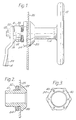
- Fig. 1 is a side view of a so-called rotary bolt or friction door lock, as it is often used in electrical cabinets. It consists of a lock bearing 10, in which an actuating shaft 14 having a toggle handle 12 at its free end is rotatably supported by 90 °. The angle of rotation is limited by a nose 16, which is attached to the actual grater 18 and strikes a stop at two stop surfaces 20 at the end of the bearing cylinder 10 to limit the angle of rotation.
- the grater is fastened to the actuating shaft 14 by means of a screw 22 and slides with its grater surface 24 on a corresponding path of the door frame when the control cabinet door is closed.
- the handle can also be removable, for example by providing a square on the actuating shaft 14 within the bearing 10, onto which a key provided with a corresponding square recess can be attached. Other embodiments such as triangular, double beard, etc. are also possible.
- the bearing 10 and handle 12 if these consist mostly of metal, must be electrically connected to the wall panel 26 of the door leaf, so that this is not caused by a wire that is torn off inside the cabinet and is under tension, for example touching the grater 18 Bearing 10 and the handle 12 under Get tense.
- the opposite surface 32 of the sheet 26 was scraped bare, on which the bearing surface of a fastening nut 34 comes to rest, in which the overall arrangement after being pushed through is fixed by a corresponding punching in the wall sheet 26 by screwing the nut 34 onto a corresponding thread 36 is, the bearing 10 is secured against rotation by flattenings 38 within the punched.
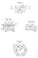
- FIG. 3 shows a fastening nut 34, the two side surfaces 50 of which are provided with teeth 40 which are sharp in the tightening direction and whose tip protrudes beyond the bearing surface 50 for scratching on non-conductive layers 74 (see FIGS. 4, 5a and 5b), and so on to establish an electrical contact between the lateral contact surface 50 of the fastening nut 34 and the metallic wall, here the door leaf 26.
- One of the several teeth 40 that are sharp in the tightening direction (usually a clockwise direction of rotation) is shown in an enlarged top view.
- Fig. 4 and from Fig. 5a which shows a section through Fig.
- the tooth is arranged so that it with its tip 42 when tightening the nut 34 what leads to a movement of the tooth tip 42 with respect to the sheet 26 to the right, scrapes the lacquer layer or oxide layer 44 down to the bare metal of the sheet 26, the scraped-off lacquer or oxide chips 46 expediently being able to collect in a depression 48, which is in front of the tooth tip 42 is provided, as can also be seen in FIG. 5b.
- Tooth tip 42 and countersink 48 can be formed in a particularly favorable manner at the same time that material is thrown up with a suitable tool by pressing into the surface 50 of the nut 34 in such a way that the tip 42 results.
- the tool could be placed obliquely in the direction of the sharpness of the tooth 42 to be formed in the surface 50 and brought to penetrate into the material, the tool simultaneously forming the depression 48 and the material throw-up 42, which automatically indicates a certain sharpness receives its top position if a suitable material is selected for nut 34.
- Brass, hard bronze or steel are particularly suitable for this purpose.
- a simple grain or chisel can be used, but for the cheapest possible production, a machine specially designed for this purpose is of course preferable, with which the teeth and the corresponding depressions on both sides of the fastening nut are produced simultaneously by using appropriate tools the side surfaces of the fastening nut act in, for example, only a single operation.
- the layer 44 of varnish or oxide thin has for example a thickness of less than 50 x 10- e m, also includes the nut 34, the normally standard threaded and the other parts are made accurately, there is less than one revolution between the beginning of the scratching and the final tightening of the screw 34.
- the side surface 50 of the fastening nut 34 approaches the surface 52 of the sheet 26 more and more, while at the same time the apex 42a becomes blunt, as shown in FIG. 5b, while the chips 46, if not in any case, move fall out of the area of the fastening nut 34 because of the vertical arrangement of the metal wall 26, collect in the depression 48.
- the remaining blunted tip 42a will press a little into the material of the sheet 26 and not only bring about an even closer electrical contact with an even lower contact resistance, but also a locking of the fastening nut 34.
- each tooth 40 has a smaller width 54 than the cross-sectional width 56 on the bearing surface 50 of the fastening nut 34. After all, a relatively wide area of the sheet 26 is still scratched free. For particularly hard materials, however, it may be cheaper to make the tooth 40 considerably narrower than the full width 56 of the contact surface 50 of the fastening nut 34, in order to make it even sharper Get scratching effect. In this case, it may be advantageous to arrange a plurality of teeth at radially different distances R from the axis of the nut 34, the difference in distance in each case corresponding approximately to the width 54 of the individual teeth 40 or also being slightly smaller.
- the insulating layer 44 would be removed in strips from the individual teeth, so that after, for example, one full turn of the nut 34, the lacquer would be scraped off in a manner that would correspond to the staggered width of the teeth 40.
- the fastening nut shown in FIG. 3 can be solid, but, as will be explained in more detail below, it can also be punched out of sheet metal and / or deep-drawn. result in considerable material savings.
- the fastening nut will then be made of sheet steel, because steel can be machined particularly well in the form specified and sufficient stability is ensured even when thin-walled material is used.
- the toothed fastening nut can be formed by deep drawing or pressing in one or at most two working steps.
- the deep-drawing tools required for this are complex, but allow simple and extremely inexpensive manufacture.
- a fastening nut according to the invention with teeth which have the shape shown in FIG. 4 can be produced simultaneously with an appropriate tool in a single operation by obliquely pressing in tool tips on both side surfaces, the tooth groups which are sharp in the tightening direction being produced simultaneously.
- the torques created by the oblique placement essentially compensate each other, so that holding the blank is either unnecessary or requires only slight holding forces.
- the machining forces are rather applied in that the opposing tool parts, which grip the two sides of the fastening nut, engage the fastening nut while simultaneously pressing and slightly rotating the tool halves, while simultaneously pressing out the material 42 and the depression 48 on both sides for all effect teeth to be generated simultaneously.
Landscapes
- Engineering & Computer Science (AREA)
- Mechanical Engineering (AREA)
- Connection Of Plates (AREA)
- Elimination Of Static Electricity (AREA)
- Lock And Its Accessories (AREA)
- Patch Boards (AREA)
Claims (6)
Priority Applications (1)
| Application Number | Priority Date | Filing Date | Title |
|---|---|---|---|
| AT80100170T ATE10048T1 (de) | 1979-09-08 | 1980-01-15 | Befestigungsmutter zur befestigung von aus metall bestehenden verschluessen fuer schaltschranktueren. |
Applications Claiming Priority (2)
| Application Number | Priority Date | Filing Date | Title |
|---|---|---|---|
| DE2936405 | 1979-09-08 | ||
| DE19792936405 DE2936405A1 (de) | 1979-09-08 | 1979-09-08 | Erdungsmutter |
Publications (3)
| Publication Number | Publication Date |
|---|---|
| EP0025472A1 EP0025472A1 (fr) | 1981-03-25 |
| EP0025472B1 EP0025472B1 (fr) | 1984-10-24 |
| EP0025472B2 true EP0025472B2 (fr) | 1991-07-10 |
Family
ID=6080419
Family Applications (1)
| Application Number | Title | Priority Date | Filing Date |
|---|---|---|---|
| EP80100170A Expired - Lifetime EP0025472B2 (fr) | 1979-09-08 | 1980-01-15 | Ecrou de fixation de fermeture de porte d'armoire électrique pour la fixation de fermetures en métal pour des portes d'armoire électrique |
Country Status (3)
| Country | Link |
|---|---|
| EP (1) | EP0025472B2 (fr) |
| AT (1) | ATE10048T1 (fr) |
| DE (2) | DE2936405A1 (fr) |
Families Citing this family (14)
| Publication number | Priority date | Publication date | Assignee | Title |
|---|---|---|---|---|
| DE3932939B4 (de) * | 1989-10-03 | 2007-09-20 | Dieter Ramsauer | Mittels Erdungs- und/oder Befestigungsfeder in dem Durchbruch einer Blechwand, wie Schaltschranktür befestigbarer Verschluß |
| DE8911765U1 (de) * | 1989-10-03 | 1991-01-31 | Ramsauer, Dieter, 5620 Velbert | Verschlußgehäuse mit Flansch zur Montage in einem Durchbruch einer dünnwandigen Fläche, insbesondere Blechschranktür oder Blechkastendeckel |
| DE4006706C2 (de) * | 1990-03-03 | 1999-04-08 | Dieter Ramsauer | Vorreiberverschluß für Klappen, Seitenverkleidung, oder dgl. aus dünnem Wandmaterial |
| DE9105667U1 (de) * | 1991-05-07 | 1991-07-04 | Steinbach & Vollmann Gmbh & Co, 5628 Heiligenhaus | Erdungsmutter |
| DE9310330U1 (de) * | 1993-07-12 | 1994-11-17 | DIRAK Dieter Ramsauer Konstruktionselemente GmbH & Co. KG., 58332 Schwelm | Vorreiberverschluß zur Befestigung von Klappen, Seitenverkleidungen, für das Schließen von Türen o.ä., die aus elektrisch leitendem, mit oberflächlicher Isolierschicht versehenem Wandmaterial, wie lackiertem Stahlblech bestehen |
| DE19505227C1 (de) * | 1995-02-16 | 1996-07-11 | Schulte Gmbh & Co Kg L | Erdungsmutter |
| DE29904771U1 (de) * | 1999-03-16 | 1999-07-08 | Emka Beschlagteile Gmbh & Co. Kg, 42551 Velbert | Stangenverschluß mit Erdungseinrichtung |
| GB2417367A (en) * | 2004-08-19 | 2006-02-22 | Richard Henry Pearce | Electrical earthing nut |
| GB2454643B (en) | 2007-07-20 | 2012-02-08 | Container Components Europ Ltd | A Lock assembley |
| DE102013226768A1 (de) * | 2013-12-19 | 2015-06-25 | Vega Grieshaber Kg | Mutter |
| CN108710059A (zh) * | 2018-08-23 | 2018-10-26 | 吕清胜 | 一种煤矿井下人工远方漏电试验装置 |
| CN115681288A (zh) * | 2022-10-20 | 2023-02-03 | 一汽奔腾轿车有限公司 | 一种带接地功能的螺母与焊接螺栓配合结构及其安装方法 |
| CN115681289A (zh) * | 2022-10-20 | 2023-02-03 | 一汽奔腾轿车有限公司 | 一种带接地功能的焊接螺栓及其安装方法 |
| IT202300004293A1 (it) * | 2023-03-08 | 2024-09-08 | Bticino Spa | Dispositivo di collegamento per fissare e collegare elettricamente un pannello ad un quadro elettrico |
Citations (1)
| Publication number | Priority date | Publication date | Assignee | Title |
|---|---|---|---|---|
| DE7621270U1 (de) † | 1976-07-06 | 1976-12-23 | Fa. Emil Krachten Jun., 5620 Velbert | Stangenverschluss |
Family Cites Families (15)
| Publication number | Priority date | Publication date | Assignee | Title |
|---|---|---|---|---|
| DE460955C (de) * | 1928-06-08 | Ernst Welker | Schraubenmuttersicherung | |
| DE319339C (de) * | 1918-09-25 | 1920-03-04 | Aeg | Elektrisch leitende Verbindung |
| US2112494A (en) * | 1937-11-02 | 1938-03-29 | Illinois Tool Works | Locking means for screw threaded fasteners |
| DE1034739B (de) * | 1955-04-06 | 1958-07-24 | Siemens Ag | Erdungs- oder Nullungsanordnung fuer gekapselte elektrische Verteilungsanlagen |
| DE1090468B (de) * | 1956-04-19 | 1960-10-06 | Illinois Tool Works | Mit Gewinde versehenes Befestigungselement |
| DE1489563B2 (de) * | 1964-10-26 | 1970-02-05 | Trilux-Lenze KG, 5760 Neheim-Hüsten | Zahnunterlegscheibe zur Herstellung einer elektrischleitenden Verbindung |
| DE1230876B (de) * | 1964-11-30 | 1966-12-22 | Alois Schiffmann Dipl Kfm | Klemme zur Kontaktgabe an einem elektrischen Leiter, insbesondere zum Erden einer Schiene |
| FR1487667A (fr) * | 1966-07-25 | 1967-07-07 | Illinois Tool Works | Rondelle élastique de freinage bombée |
| GB1283036A (en) * | 1968-11-07 | 1972-07-26 | Albert Leonard Pike | Improvements in and relating to nut like securing devices for securing or locking electric fittings or components |
| US3528050A (en) * | 1969-05-02 | 1970-09-08 | Holub Ind Inc | Push-on type grounding clip |
| GB1298759A (en) * | 1970-03-09 | 1972-12-06 | Albert Leonard Pike | Improvements in and relating to nuts |
| JPS5111031Y1 (fr) * | 1970-03-24 | 1976-03-25 | ||
| CA969846A (en) * | 1972-11-02 | 1975-06-24 | Julius P. Andrasik | Reducing assembly |
| US4060301A (en) * | 1974-03-12 | 1977-11-29 | Beatty Albert W | Electrical connector for transmission line insulators |
| DE2641177A1 (de) * | 1976-09-13 | 1978-03-16 | Wolf Dipl Ing Riebling | Sicherung fuer schrauben oder muttern gegen unbeabsichtigtes loesen |
-
1979
- 1979-09-08 DE DE19792936405 patent/DE2936405A1/de not_active Ceased
-
1980
- 1980-01-15 AT AT80100170T patent/ATE10048T1/de not_active IP Right Cessation
- 1980-01-15 DE DE8080100170T patent/DE3069475D1/de not_active Expired
- 1980-01-15 EP EP80100170A patent/EP0025472B2/fr not_active Expired - Lifetime
Patent Citations (1)
| Publication number | Priority date | Publication date | Assignee | Title |
|---|---|---|---|---|
| DE7621270U1 (de) † | 1976-07-06 | 1976-12-23 | Fa. Emil Krachten Jun., 5620 Velbert | Stangenverschluss |
Non-Patent Citations (3)
| Title |
|---|
| "Elektrotechnische Zeitschrift", Ausgabe A(etz-a), Band 99(1978), Heft 2, S.89-92 † |
| Bulten-Poroduktinformation, P1, Nr. 79 DSE, Feb. 79 † |
| VDE-0660, Teil 5, 11.67, Seite 35 † |
Also Published As
| Publication number | Publication date |
|---|---|
| EP0025472A1 (fr) | 1981-03-25 |
| DE3069475D1 (en) | 1984-11-29 |
| EP0025472B1 (fr) | 1984-10-24 |
| ATE10048T1 (de) | 1984-11-15 |
| DE2936405A1 (de) | 1981-03-26 |
Similar Documents
| Publication | Publication Date | Title |
|---|---|---|
| EP0025472B2 (fr) | Ecrou de fixation de fermeture de porte d'armoire électrique pour la fixation de fermetures en métal pour des portes d'armoire électrique | |
| DE3610392C2 (de) | Schraube für verunreinigte Gewindebohrungen | |
| EP2193573B1 (fr) | Dispositif électrique | |
| EP0694988A2 (fr) | Casse pour câble avec système de fiscation | |
| EP0634550B1 (fr) | Fermeture tournante | |
| DE4024293C2 (de) | Rastklammer für einen Elektroinstallations-Wandkanal | |
| WO2012130234A1 (fr) | Liaison vissée électroconductrice et douille spéciale pour une telle liaison vissée | |
| DE3517933C2 (de) | Schloßmechanismus mit einer Sperrklinkenwelle | |
| EP0786827B1 (fr) | Dispositif de serrage pour la connexion électrique d'un câble | |
| DE2855216A1 (de) | Beschlag zum verbinden zweier moebelteile | |
| DE19860085B4 (de) | Selbstschneidendes metallisches Gewindeteil | |
| DE2854121C2 (de) | An ein Maschinenteil ansetzbare Vorrichtung zum Ausstechen von Ringlippen dort in Bohrungen eingestemmter Lagerbüchsen | |
| EP0056982B1 (fr) | Came pour loqueteau | |
| EP0545158A1 (fr) | Dispositif à vis | |
| DE3001350A1 (de) | Erdungsbefestigung | |
| DE102014014086A1 (de) | Schraube und Schraubenanordnung | |
| DE3019084C2 (de) | Stanzwerkzeug und Verfahren zur Herstellung einer Mutter | |
| EP2088645B1 (fr) | Système de fixation | |
| EP0514924B1 (fr) | Vis de contact | |
| DE1090468B (de) | Mit Gewinde versehenes Befestigungselement | |
| DE7925488U1 (de) | Erdungsmutter | |
| DE102015016365A1 (de) | Schraube | |
| DE202020103613U1 (de) | Mit zwei Drehmeißeln ausgestattete Lochsäge zum drehenden Lochschneiden | |
| EP4256210B1 (fr) | Rondelle de recouvrement de fentes | |
| DE2527557A1 (de) | Reibschlusschraube |
Legal Events
| Date | Code | Title | Description |
|---|---|---|---|
| PUAI | Public reference made under article 153(3) epc to a published international application that has entered the european phase |
Free format text: ORIGINAL CODE: 0009012 |
|
| AK | Designated contracting states |
Designated state(s): AT BE CH DE FR GB IT LU NL SE |
|
| 17P | Request for examination filed |
Effective date: 19810704 |
|
| ITF | It: translation for a ep patent filed | ||
| GRAA | (expected) grant |
Free format text: ORIGINAL CODE: 0009210 |
|
| AK | Designated contracting states |
Designated state(s): AT BE CH DE FR GB IT LU NL SE |
|
| PG25 | Lapsed in a contracting state [announced via postgrant information from national office to epo] |
Ref country code: NL Effective date: 19841024 Ref country code: BE Effective date: 19841024 |
|
| REF | Corresponds to: |
Ref document number: 10048 Country of ref document: AT Date of ref document: 19841115 Kind code of ref document: T |
|
| REF | Corresponds to: |
Ref document number: 3069475 Country of ref document: DE Date of ref document: 19841129 |
|
| PG25 | Lapsed in a contracting state [announced via postgrant information from national office to epo] |
Ref country code: AT Effective date: 19850115 |
|
| PG25 | Lapsed in a contracting state [announced via postgrant information from national office to epo] |
Ref country code: LU Free format text: LAPSE BECAUSE OF NON-PAYMENT OF DUE FEES Effective date: 19850131 Ref country code: CH Effective date: 19850131 |
|
| ET | Fr: translation filed | ||
| NLV1 | Nl: lapsed or annulled due to failure to fulfill the requirements of art. 29p and 29m of the patents act | ||
| PLBI | Opposition filed |
Free format text: ORIGINAL CODE: 0009260 |
|
| PLBI | Opposition filed |
Free format text: ORIGINAL CODE: 0009260 |
|
| 26 | Opposition filed |
Opponent name: STEINBACH & VOLLMANN GMBH & CO. Effective date: 19850712 |
|
| 26 | Opposition filed |
Opponent name: BULTEN AB Effective date: 19850715 |
|
| REG | Reference to a national code |
Ref country code: CH Ref legal event code: PL |
|
| ITTA | It: last paid annual fee | ||
| PUAH | Patent maintained in amended form |
Free format text: ORIGINAL CODE: 0009272 |
|
| STAA | Information on the status of an ep patent application or granted ep patent |
Free format text: STATUS: PATENT MAINTAINED AS AMENDED |
|
| 27A | Patent maintained in amended form |
Effective date: 19910710 |
|
| AK | Designated contracting states |
Kind code of ref document: B2 Designated state(s): AT BE CH DE FR GB IT LU NL SE |
|
| ET3 | Fr: translation filed ** decision concerning opposition | ||
| ITF | It: translation for a ep patent filed | ||
| PGFP | Annual fee paid to national office [announced via postgrant information from national office to epo] |
Ref country code: SE Payment date: 19920117 Year of fee payment: 13 |
|
| PGFP | Annual fee paid to national office [announced via postgrant information from national office to epo] |
Ref country code: DE Payment date: 19920121 Year of fee payment: 13 |
|
| PGFP | Annual fee paid to national office [announced via postgrant information from national office to epo] |
Ref country code: FR Payment date: 19920122 Year of fee payment: 13 |
|
| PGFP | Annual fee paid to national office [announced via postgrant information from national office to epo] |
Ref country code: GB Payment date: 19920413 Year of fee payment: 13 |
|
| PG25 | Lapsed in a contracting state [announced via postgrant information from national office to epo] |
Ref country code: GB Effective date: 19930115 |
|
| PG25 | Lapsed in a contracting state [announced via postgrant information from national office to epo] |
Ref country code: SE Effective date: 19930116 |
|
| GBPC | Gb: european patent ceased through non-payment of renewal fee |
Effective date: 19930115 |
|
| PG25 | Lapsed in a contracting state [announced via postgrant information from national office to epo] |
Ref country code: FR Effective date: 19930930 |
|
| PG25 | Lapsed in a contracting state [announced via postgrant information from national office to epo] |
Ref country code: DE Effective date: 19931001 |
|
| REG | Reference to a national code |
Ref country code: FR Ref legal event code: ST |
|
| EUG | Se: european patent has lapsed |
Ref document number: 80100170.2 Effective date: 19930810 |
|
| APAC | Appeal dossier modified |
Free format text: ORIGINAL CODE: EPIDOS NOAPO |
|
| APAC | Appeal dossier modified |
Free format text: ORIGINAL CODE: EPIDOS NOAPO |
|
| APAH | Appeal reference modified |
Free format text: ORIGINAL CODE: EPIDOSCREFNO |