EP0023067B1 - Bandaufzeichnungs- oder -wiedergabegerät mit rotierendem Magnetkopf - Google Patents
Bandaufzeichnungs- oder -wiedergabegerät mit rotierendem Magnetkopf Download PDFInfo
- Publication number
- EP0023067B1 EP0023067B1 EP80200691A EP80200691A EP0023067B1 EP 0023067 B1 EP0023067 B1 EP 0023067B1 EP 80200691 A EP80200691 A EP 80200691A EP 80200691 A EP80200691 A EP 80200691A EP 0023067 B1 EP0023067 B1 EP 0023067B1
- Authority
- EP
- European Patent Office
- Prior art keywords
- drum
- magnetic
- tape
- magnetic tape
- head
- Prior art date
- Legal status (The legal status is an assumption and is not a legal conclusion. Google has not performed a legal analysis and makes no representation as to the accuracy of the status listed.)
- Expired
Links
Images


Classifications
-
- G—PHYSICS
- G11—INFORMATION STORAGE
- G11B—INFORMATION STORAGE BASED ON RELATIVE MOVEMENT BETWEEN RECORD CARRIER AND TRANSDUCER
- G11B15/00—Driving, starting or stopping record carriers of filamentary or web form; Driving both such record carriers and heads; Guiding such record carriers or containers therefor; Control thereof; Control of operating function
- G11B15/02—Control of operating function, e.g. switching from recording to reproducing
- G11B15/12—Masking of heads; circuits for Selecting or switching of heads between operative and inoperative functions or between different operative functions or for selection between operative heads; Masking of beams, e.g. of light beams
- G11B15/14—Masking or switching periodically, e.g. of rotating heads
-
- G—PHYSICS
- G11—INFORMATION STORAGE
- G11B—INFORMATION STORAGE BASED ON RELATIVE MOVEMENT BETWEEN RECORD CARRIER AND TRANSDUCER
- G11B15/00—Driving, starting or stopping record carriers of filamentary or web form; Driving both such record carriers and heads; Guiding such record carriers or containers therefor; Control thereof; Control of operating function
- G11B15/18—Driving; Starting; Stopping; Arrangements for control or regulation thereof
- G11B15/1808—Driving of both record carrier and head
-
- G—PHYSICS
- G11—INFORMATION STORAGE
- G11B—INFORMATION STORAGE BASED ON RELATIVE MOVEMENT BETWEEN RECORD CARRIER AND TRANSDUCER
- G11B5/00—Recording by magnetisation or demagnetisation of a record carrier; Reproducing by magnetic means; Record carriers therefor
- G11B5/48—Disposition or mounting of heads or head supports relative to record carriers ; arrangements of heads, e.g. for scanning the record carrier to increase the relative speed
- G11B5/52—Disposition or mounting of heads or head supports relative to record carriers ; arrangements of heads, e.g. for scanning the record carrier to increase the relative speed with simultaneous movement of head and record carrier, e.g. rotation of head
- G11B5/53—Disposition or mounting of heads on rotating support
- G11B5/531—Disposition of more than one recording or reproducing head on support rotating cyclically around an axis
- G11B5/534—Disposition of more than one recording or reproducing head on support rotating cyclically around an axis inclined relative to the direction of movement of the tape, e.g. for helicoidal scanning
Definitions
- the invention relates to a recording and / or reproducing device with at least one head drum which can be driven to rotate in a predetermined direction of rotation at a predetermined speed and has at least one magnetic head, which head drum forms part of a drum-shaped tape guide arranged in the region of the magnetic head for a magnetic tape which has at least one Section of the lateral surface of the tape guide and the magnetic head rotating at a predetermined level can be guided, the magnetic head scanning oblique parallel tracks in a predetermined scanning direction between the tape edge and tape center in a predetermined track pattern of two track patterns lying within one of the two longitudinal halves of the magnetic tape and with a drive device for moving the magnetic tape in a predetermined direction of movement at a predetermined speed for scanning the tracks in the predetermined track pattern.
- Such a device is known from DE-PS 1 499 627.
- this known device it is provided that the other longitudinal half of the same is used by turning over the magnetic tape, similarly as can be done with known tape recorders with half-track operation. After the magnetic tape has been turned over, the same moves in the same direction of motion as before, just as the direction of rotation of the magnetic head which can be driven in rotation is the same as before.
- Such a device was presented in the article "Philips and Grundig bring the 8-hour video recorder" in Funkschau, issue 14, July 6, 1979.
- the necessary turning over of the magnetic tape is often considered disadvantageous because it takes a certain amount of time during which no recording or playback is possible.
- the invention has set itself the goal of creating a device of the type mentioned, the turning of the cassette is unnecessary. Compatibility is to be maintained, that is to say that all video cassettes which are already wholly or partially provided with a recording by all. Devices can be played easily.
- the perfect interchangeability of cassettes and devices is of the utmost importance for every magnetic tape recording / reproduction system intended for the large audience on the market.
- the invention is set out in claim 1.
- a magnetic tape device for recording television signals is also known, see JP-OS 53-11013, in which traces running in the longitudinal direction of the magnetic tape are scanned with a stationary magnetic head, the direction of movement of the magnetic tape being reversed at the end of the tape and the magnetic head being rotated step by step on a cylindrical tape guide over which the magnetic tape is guided helically is set to another track running in the longitudinal direction of the magnetic tape.
- JP-OS 53-11013 in which traces running in the longitudinal direction of the magnetic tape are scanned with a stationary magnetic head, the direction of movement of the magnetic tape being reversed at the end of the tape and the magnetic head being rotated step by step on a cylindrical tape guide over which the magnetic tape is guided helically is set to another track running in the longitudinal direction of the magnetic tape.
- FIG. 1 shows a top view of a recording and / or reproducing device with the course of the magnetic tape from a supply reel via a drum-shaped tape guide and a rotatingly drivable magnetic head arrangement to a take-up reel.
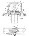
- a drum-shaped tape guide and a coaxially arranged, rotatably drivable, magnetic heads carrying drum in section along the line 11-11 of Fig. 1 is shown in detail.
- FIG. 3 shows a track pattern on the magnetic tape.
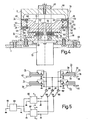
- 4 shows a drum in an analogous representation to FIG. 2 together with two drum-shaped tape guides, the magnetic heads being connected to the drum via electrically controllable positioning elements.
- 5 shows a circuit diagram for the electrical control of the positioning elements according to FIG. 4.
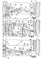
- a section of an arrangement for tracking two magnetic heads with a single electrically controllable positioning element is shown in FIG. Fig. 7 shows a drum-shaped tape guide and a drum in section along the line VII-VII of Fig. 1, and a device for transmitting an adjustment movement from the device to the drum.
- FIG. 8 shows in detail a section of the drum indicated in FIG. 7, two magnetic heads being arranged on a rocker for their adjustment.
- FIG. 8 shows in detail the same section of the drum indicated in FIG. 2, two magnetic heads being arranged on a four-bar linkage for their adjustment.
- Fig. 10 shows in detail the same section of the drum indicated in Fig. 7, wherein a single magnetic head is arranged for its adjustment in two levels on a four-bar link.
- Fig. 1 shows a circuit diagram for the electrical activation or deactivation of magnetic heads on a drum.
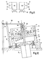
- FIG. 12 shows, in an analogous representation to FIG. 7, a drum on which a switch arrangement that can be actuated by the device is provided.
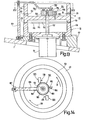
- 13 shows a drum in the same representation as in FIG. 12, on which a switch arrangement with a wing can be actuated automatically depending on the direction of rotation of the drum.
- FIG. 14 shows the arrangement according to FIG. 13 in a view along the line XIV-XIV in FIG. 13.
- FIG. 15 shows the detail of a drum on which a switch arrangement with a pendulum-shaped lever automatically depends on the direction of rotation of the
- Fig. 1 denotes the chassis of a recording and / or reproducing device on which a cassette 2 is placed.
- a magnetic tape 3 is accommodated in this cassette, which, when the device is in its initial position, runs from a tape reel 4 via a deflection roller 5 to a further deflection roller 6 and to a second tape reel 7, as is shown with broken lines.
- the cassette is provided with a recess 8 and laterally adjoining openings 9 and 10, in the area of which the magnetic tape runs.
- the tape windings 4 and 7 are carried by coils 11 and 12, which can be driven in the usual manner from winding mandrels 13 and 14 on the device side.
- the magnetic tape is led out of the cassette 2 and around the outer surface of a ro 1 drivable, schematically indicated in Fig. 1 magnetic head assembly 15 and a arranged in the area thereof, also schematically indicated, drum-shaped tape guide 16, as shown in Fig. 1 with full lines.
- Two tape deflection devices 17 and 18, which are adjustable along guideways 19 and 20, are used to transfer the magnetic tape from the cassette to the magnetic head arrangement 15 and tape guide 16.
- the band deflection devices 17 and 18 are located in the area of the recess 8 of the cassette 2, as is indicated by dotted lines.
- two guide pins 21 and 22 or 23 and 24 arranged on the tape deflection devices engage behind the magnetic tape in the region of the recess 8 of the cassette.
- the guide pins 21, 22 and 23, 24 capture the magnetic tape, whereby it is pulled out of the cassette and around it Magnetic head assembly 15 and tape guide 16 is looped.
- the magnetic tape also comes into operative connection with fixed magnetic heads 27 and 28, which are used in the usual way to record, play back or delete additional information in their own longitudinal tracks on the magnetic tape.
- a helical looping of the tape guide 16 and magnetic head arrangement 15 is provided at approximately 180 °.
- the magnetic head arrangement 15 has two magnetic heads 29 and 30 rotating at a predetermined level, which are offset from one another by approximately 180 °, so that when the magnetic head arrangement is rotated with a predetermined direction of rotation indicated by the arrow 31, each of the two magnetic heads successively scans one oblique track on the magnetic tape.
- the tape guide 16 and the magnetic head arrangement 15 are arranged on the chassis 1 inclined at a certain angle a in the direction away from the cassette.
- the magnetic tape runs from the guide pin 22 parallel to the chassis 1 to the tape guide 16 and magnetic head arrangement 15 and leaves them inclined toward the guide pin 23 at an angle 2a to the chassis 1.
- the tape deflection device 18 is inclined in its operating position, for example by a corresponding spatial course of the guideway 20, in an analogous manner by the angle 90 ° ⁇ 2 ⁇ , so that the magnetic tape leaving the guide pin 24 around the Angle 2a rises towards the cassette.
- the magnetic tape is again deflected into a parallel path to the chassis 1, after which it can enter the cassette to the deflection roller 6.
- the angle of inclination ⁇ of the tape guide 16 and magnetic head arrangement 15 is selected such that the magnetic heads 29 and 30, as indicated in FIG. 3, successively, obliquely running tracks 34, 35 etc., each lying within a longitudinal half 33 of the magnetic tape 3. scan.
- the individual tracks can either run from the relevant edge of the magnetic tape to its center or from the center of the magnetic tape to its edge, which depends on how the magnetic head arrangement runs relative to the magnetic tape. In the area of the edge and the center of the magnetic tape, relatively narrow zones can remain free, in which longitudinal tracks can then be accommodated, which are scanned with the magnetic heads 27 and 28, respectively.
- wrapping of the tape guide 16 and magnetic head arrangement 15 could also be selected, such as with a wrapping angle of approximately 360 ° or with a wrapping angle of less than 180 °, the number of required magnetic heads then being analogous to one or more than two changes, as is well known from the prior art.
- the magnetic tape with respect to a predetermined direction of movement for example from the tape reel 4 via the tape guide 16 and magnetic head arrangement 15 to the tape reel 7, as indicated in Fig. 1 by the arrow 36 in which the magnetic tape with a predetermined Speed for scanning the tracks is driven, optionally can also be driven in the opposite direction of movement with the predetermined speed for scanning the tracks.
- the magnetic tape then runs in this opposite direction of movement from the tape reel 7 via the tape guide 16 and magnetic head arrangement 15 to the tape reel 4, as is indicated in FIG. 1 by the arrow 37.
- a drive device 44 is provided for the magnetic tape in the present exemplary embodiment, which drive device can be driven in opposite directions of rotation, each with a pressure roller 45 or 46 cooperating drive shafts 47 and 48, of which the drive shaft 47 seen in the predetermined direction of movement 36 of the magnetic tape and the drive shaft 48 in the opposite direction of movement 37 of the magnetic tape is arranged after the tape guide 16 and magnetic head assembly 15.
- the drive shafts 47 and 48 are in this case mounted on the chassis 1, whereas the pressure rollers 45 and 46 assigned to them are arranged on the adjustable belt deflection devices 18 and 17, so that they can optionally be brought into operative connection with the magnetic tape and the corresponding drive shaft.
- the drive shaft 47 works together with a section of the magnetic tape which is inclined at an angle 2a with respect to the chassis, which is why this drive shaft is arranged on the chassis in such a way that it is perpendicular to this section of the magnetic tape and thus axially parallel to the Guide pins 23, 24 and the pressure roller 45 runs on the belt deflection device 18.
- the drive shaft 48 cooperates with a section of the magnetic tape which runs parallel to the chassis, which is why it is arranged perpendicular to the chassis, in which case it then runs axially parallel to the guide pins 21, 22 and the pressure roller 46 on the tape deflection device 17.
- the drive shaft arranged after the tape guide 16 and magnetic head arrangement 15, as seen in the relevant direction of movement of the magnetic tape is effective.
- the belt deflection device 18 is adjusted so far in the direction of the arrow 26 that the pressure roller 45 arranged on it is in operative connection with the magnetic tape and the drive shaft 47.
- the belt deflection device 17 is adjusted in the direction of arrow 25 only into the area of the drive shaft 48, so that the pressure roller 46 arranged on it is not in operative connection with the drive shaft 48, so that this drive shaft is not in operation in this direction of movement of the magnetic tape.
- Such a drive device 44 with two drive shafts 47 and 48 which can be driven in opposite directions of rotation and are arranged in the described manner relative to the tape guide 16 and magnetic head arrangement 15, results in an exact run of the same over the tape guide 16 in both directions of movement 36 and 37 of the magnetic tape and magnetic head assembly 15, which is very important in terms of proper recording or reproduction of the signals.
- a drive device could also be constructed differently, for example in such a way that only one drive shaft is provided, to which the section of the magnetic tape running from the tape guide 16 and magnetic head arrangement 15 runs with one of two pressure rollers, with a corresponding reversal of the direction of rotation Drive shaft, is brought into operative connection.
- a support plate 49 is attached to the chassis 1, which carries the tape guide 16 and magnetic head assembly 15.
- the band guide 16 here consists of a hollow drum attached to the support plate 49, on the bottom surface 50 of which a motor 51 is flanged coaxially, the drive shaft 52 of which passes through the drum.
- a further hollow drum 53 is fastened on this drive shaft 52, which forms a gap 55 with a drum edge 54 in relation to the free edge 56 of the band guide 16.
- This drum 53 which can be driven in rotation by the motor 51, serves as a carrier for the magnetic heads of the magnetic head arrangement 15.
- the lateral surface 57 of the tape guide 16 there is one helical step 58 incorporated, starting from the free edge 56 of the tape guide, falling by essentially half the width of the magnetic tape in the direction of the chassis and extending 180 ° around the tape guide.
- the step 58 forms a guide for an edge of the magnetic tape 3, which here runs along the stepped lateral surface 59 of the tape guide 16, which also acts as a guide.
- a further guide for the magnetic tape is formed by the outer surface 60 of the drum 53, along which the magnetic tape is also guided over essentially a full width over a section of 180 °. This wrapping of the tape guide 16 and the drum 53 through the magnetic tape 3 can be seen from FIG.
- the magnetic tape 3 runs in the direction of movement 36 on the tape guide 16, guided by the step 58 on the same, only in the region of the free edge 56 on its stepped lateral surface 59, around it after the helical looping by 180 ° with approximately half the width to leave the magnetic tape again.
- the effective in the predetermined direction of movement 36 of the magnetic tape magnetic heads 29 and 30 of the magnetic head assembly 15 are arranged in a known manner in the region of the drum rim 54 diametrically opposite to each other on the drum 53, whereby they rotate at a predetermined level and in the wrap area of 180 ° with the Connect magnetic tape 3.
- the magnetic heads 29 and 30 scan oblique tracks 34, 35, etc., each lying within the longitudinal half 33 of the magnetic tape 3.
- openings 61 and 62 are now provided on the drum 53, which are seen in relation to the drum edge 54, viewed in the axial direction of the drum, essentially by one Amount half the width of the magnetic tape given offset.
- a further magnetic head 39 or 40 of the magnetic head arrangement 15 is arranged in each of these openings 61 and 62, as a result of which they rotate at a further level, which is essentially one by the amount compared to the predetermined level at which the magnetic heads 29 and 30 rotate half the width of the magnetic tape is given the distance.
- the magnetic heads 39 and 40 also come into operative connection with the magnetic tape, since this also wraps around the drum 53 at a further level by 180 °. If the drum 53 is driven with the direction of rotation 38 opposite the predetermined direction of rotation 31 by reversing the polarity of the motor 51, then the magnetic heads 39 and 40 feel oblique tracks 42, 43 etc., each lying within the second longitudinal half 41 of the magnetic tape 3. when the magnetic tape is moved in the direction of movement 37 opposite to the predetermined direction of movement 36, as can be seen from FIG. 3.
- all four magnetic heads 29, 30, 39 and 40 of the magnetic head arrangement 15 are therefore always in operative connection with the magnetic tape 3. It is therefore further provided that, depending on the direction of rotation of the drum 53, only the two magnetic heads 29, 30 and 39, 40 are always electrically activated, which are at the level which is assigned to that longitudinal half of the magnetic tape in which relevant direction of rotation of the drum 53 and the corresponding direction of movement of the magnetic tape, the tracks to be scanned. In the direction of rotation 31 of the drum 53, the magnetic heads 29 and 30 and in the direction of rotation 38 of the drum 53, the magnetic heads 39 and 40 are therefore electrically activated in that the useful signal is supplied to them during recording or the signal supplied by them is removed during playback .
- a rotating transformer the stationary half 63 of which is attached to the tape guide 16 and the rotating half 64 of which is attached to the drum 53, is used to feed or discharge the signals to the magnetic heads.
- These transformer halves each have four opposing and thus electrically coupled ring windings, the ring windings provided on the rotating transformer half 63 each being connected to one of the four magnetic heads in a manner not shown, whereas the ring windings provided on the stationary transformer half 63 are connected to the electrical circuit of the device are connected.
- a drum 53 is again provided as a carrier for four magnetic heads 29, 30, 39 and 40, the magnetic heads 29 and 30 again rotating at the predetermined level and the magnetic heads 39 and 40 rotating at a further level, that is the predetermined level is substantially offset by a distance given by the amount of half the width of the magnetic tape, seen in the axial direction of the drum.
- the magnetic heads 29 and 30 are again arranged in the region of the edge 54 of the drum 53.
- the drum 53 has a height which essentially only corresponds to approximately half the width of the magnetic tape. This makes it possible to arrange the magnetic heads 39 and 40 in the region of the second edge 65 of this drum, which lies opposite the edge 54 thereof. In this way, the drum 53 is easier to manufacture by itself.
- a band guide 16 designed as a drum interacts again Men, on which the motor 51 is flanged, on the axis 52, the drum 53 is attached. Otherwise, this band guide 16 is completely analogous to that according to the embodiment of FIG. 2.
- the magnetic heads 29 and 30 again run in a gap 55 which is formed between the edge 54 of the drum 53 and the free edge 56 of the tape guide 16. Since, in the present exemplary embodiment, as can be seen, the drum 53, which carries the magnetic heads and has only a height corresponding to half the width of the magnetic tape, with its outer surface 60 cannot support and guide the magnetic tape 3 over its essentially entire width, is another Drum 66 is provided as an additional tape guide.
- This drum 66 is arranged coaxially to the band guide 16 and the drum 53, the edge 65 thereof opposite and fixedly connected to the band guide 16 with an L-shaped bracket 67 which surrounds the drum 53.
- a gap 69 is also formed between the free edge 68 of the drum 66 facing the drum 53, analogous to the gap 55, in which the magnetic heads 39 and 40 now run.
- the lateral surface 70 of the drum 66 forms in the usual way a guide surface for the magnetic tape 3, which wraps around this drum 66 in sections in a helical area in a range of 180 °, analogously to the case with the tape guide 16. This again ensures exact guidance of the magnetic tape around the magnetic head arrangement.
- each of the magnetic heads 29, 30, 39 and 40 is connected to the drum via an electrically controllable positioning element 71, 72, 73 and 74, which could of course also be the case in the exemplary embodiment according to FIG. 2.
- Such positioning elements serve to guide the magnetic head in question along the tracks to be scanned by it. They consist, for example, of piezoelectric ceramic elements which, as can be seen more clearly from FIG. 5, are each composed of two disks 75 and 76, between which an electrode 77 runs and which also each carry an electrode 78 and 79 on their outside .
- the magnetic head is arranged at the free end of such a positioning element.
- the positioning elements By supplying appropriate electrical control signals to the electrodes, the positioning elements can be bent in a circular arc, perpendicular to their main surfaces in both directions, to a greater or lesser extent, as a result of which the magnetic head in question can be adjusted transversely to the track to be scanned and can thus be guided exactly along this track .
- the design and control of such positioning elements is described in detail, for example, in DE-OS 2 741 217.
- the outer electrodes 78 and 79 of such a positioning element are electrically connected to one another, so that two electrical connections are required for such a positioning element. Since the magnetic heads 29 and 30 in one direction of movement of the magnetic tape and the magnetic heads 39 and 40 in the opposite direction of movement of the magnetic tape each scan for adjacent tracks, it is necessary for the positioning elements 71 and 72 or 73 and 74 assigned to these magnetic heads each for to supply control signals which carry out the corresponding track correction. A total of five connections would therefore be required for four positioning elements with a common ground connection. Since such connections must be routed to the rotating drum 53 via slip rings, the aim is to keep the number of these connections as small as possible.
- two positioning elements are therefore expediently electrically connected in parallel, which are assigned to the magnetic heads, which are provided in pairs, alternately depending on the direction of rotation of the drum 53, for scanning the tracks lying within the two longitudinal halves of the magnetic tape, and which are provided when the drum rotates are in operative connection with the magnetic tape at the same time.
- the magnetic heads that are not in operation are also adjusted in the same way as the magnetic heads currently used to scan the tracks in one of the two longitudinal halves of the magnetic tape, but this is meaningless since these magnetic heads are not in operation.
- the positioning elements 71 and 74 and the positioning elements 72 and 73 are each connected in parallel, which means that only three connections to the four positioning elements are required.
- These three connections are formed by three concentric contact rings 80, 81 and 82 provided on the drum 53, which are connected to sliding contacts 83, 84 and 85 arranged on the band guide 16.
- the sliding contact 84 forms the ground connection
- the sliding contact 83 is connected to a first control signal generator 86
- the sliding contact 85 is connected to a second control signal generator 87.
- the two control signal generators emit either a positive or negative control signal and, depending on the amount of the track deviation, a control signal with a corresponding amplitude, which in turn deflects the positioning elements accordingly.
- the two control signal generators 86 and 87 are controlled by a circuit arrangement 88, which supplies control signals which are proportional to the corresponding track deviation signals, which are fed to the input 89 of the circuit arrangement 88, but the acquisition of which need not be discussed here, since such measures are in the present context are not essential to the invention.
- FIG. 1 Another embodiment for guiding the magnetic heads along the tracks to be scanned by them is shown in FIG. 1, with a drum 53, tape guides 16 and others Drum 66 is assumed, as described in the embodiment of FIG. 4.
- the magnetic heads 29 and 40 which are again each in operative connection with the magnetic tape 3, are arranged on a common holder 90 which passes through a slot 91 provided on the drum 53 and defines the two levels for the magnetic heads 29 and 40.
- This holder 90 is now connected to the drum 53 via a single electrically controllable positioning element 92, as a result of which the two magnetic heads 29 and 40 are guided along the tracks in accordance with the deflection of this positioning element.
- a leaf spring 93 running parallel to the positioning element 92 is connected to the holder 90, which in turn is attached to the drum 53.
- the positioning element 92 and the leaf spring 93 together form a parallel guide for the holder 90.
- the magnetic heads rotating in both levels are operatively connected to the magnetic tape alternately in pairs when the drum rotates.
- the magnetic heads depending on the direction of movement of the magnetic tape, only those magnetic heads are activated which rotate at such a level that they scan tracks in the longitudinal half of the magnetic tape assigned to this direction of movement of the magnetic tape.
- Such an electrical activation of the magnetic heads for active scanning of the tracks takes place depending on the respective direction of movement of the magnetic tape and / or direction of rotation of the drum.
- Embodiments are described below in which a mechanical activation of the magnetic heads is provided for the active scanning of the tracks lying within the relevant longitudinal half of the magnetic tape.
- FIG. 7 shows an exemplary embodiment in this regard, a construction for the drum 53 and belt guide 16 being assumed, which is the basis of the exemplary embodiment according to FIG. 2, but this is in no way absolutely necessary.
- the actual design measures for adjusting the magnetic heads are not specified; for the sake of clarity, this is done on an enlarged scale in separate figures, in which the construction space surrounded by dashed lines in FIG. 7 and designated by reference number 94 is shown.
- an arm 95 which runs parallel to the axis 52 of the motor 51 and on which a lever 96 is pivotably mounted is fastened on the support plate 49.
- One end 97 of this lever is connected in an articulated manner to a push rod 98 which, from adjustable device parts or from a lifting magnet, carries out an adjusting movement depending on the respective direction of movement of the magnetic tape and / or direction of rotation of the drum, which is then transmitted to the lever 96.
- the other free, preferably spherical end 99 of the lever 96 engages in an annular groove 100, which is provided on a shift sleeve 101, which is slidably arranged along the axis 52, to which the hollow drum 53 is also attached.
- the selector sleeve 101 is in turn coupled to the drum 53 in a rotationally secure manner, for which purpose two arms 102 and 103, which are provided on it and lie opposite one another, each protrude into one of two recesses 104 and 105, which are provided diametrically opposite one another and extend radially on the drum 53.
- the gearshift sleeve 101 rotates together with the drum 53, but can be adjusted in the axial direction thereof with the lever 96, so that the adjustment movement of the push rod 98 can be transmitted into the interior of the drum 53.
- the lugs 102 and 103 each have at their ends, for example, a pin 106 or 107, an axle piece or the like, from which the adjustment movement can then be removed and in each case fed to the magnetic heads diametrically opposite one another on the drum.
- an adjustment device 108 for the mechanical activation of the magnetic heads 29 and 40 is shown, in which they perform a swiveling movement with respect to the lateral surface 60 of the drum 53, but this takes place essentially in the radial direction, whereby the magnetic heads are each lifted from the magnetic tape and are not adjusted along the same, so that neither damage to the very sensitive magnetic heads nor to the likewise very sensitive magnetic tape can occur.
- a rocker 109 is provided for adjusting the magnetic heads, which is pivotally mounted in the recess 105 on the drum 53.
- the rocker 109 has lateral stub axles 110 which engage in V-shaped bearing points 111, which in turn are provided laterally on the recess 105 of the drum 53.
- the magnetic heads 29 and 40 are each arranged on outer surfaces 112 and 113 of the rocker oriented in a wedge shape. Parallel to these outer surfaces are two adjusting screws 114 and 115 are provided, the free ends of which are provided for cooperation with stop surfaces 116 and 117 on the drum, as a result of which the end positions of the magnetic heads can be adjusted relative to the lateral surface 60 of the drum.
- An axis 119 is provided in a recess 118 of the rocker and serves as a point of engagement for a lever arrangement belonging to the adjusting device 108.
- This lever arrangement consists of a lever 121 which is pivotably mounted about an axis 120 in the recess 105 of the drum and which has a fork-shaped end 122 with which it is connected to the pin 107 on the shoulder 103 on the shift sleeve 101.
- an arm 124 is pivotally mounted, the free, fork-shaped end engages around the axis 119 on the rocker.
- a coil spring 125 is pushed onto this arm 124, which is supported on the one hand on a collar 126 provided on the arm 124 and on the other hand on the axis 119.
- FIG. 8 shows the adjusting device 108 and with it the rocker 109 in a position in which the magnetic head 29 is mechanically activated for active track scanning and is located in the area of the lateral surface 60 of the drum 53, whereas the magnetic head 40 is deactivated mechanically and is accordingly retracted relative to the outer surface 60 of the drum 53.
- This position of the rocker 109 which is determined by the adjusting screw 114 and determined by the spring 125, is, as can be seen, a dead center position, since the force of the spring 125 is effective on the one hand between the stop surface 116 and the V-shaped bearing 111 and on the other hand the axis 120 supporting the lever 121 is.
- the present position of the magnetic head 29 is determined exclusively by the dead center position and is therefore clearly and without play defined.
- the switching sleeve 101 is adjusted in the direction of the arrow 127, as a result of which the lever 121 and with it the arm 124 is pivoted until finally the rocker under the action of the spring 125 109 tilts into its other dead center position, in which the adjusting screw 115 then fixes the position of the magnetic head 40 relative to the running surface 60 of the drum 53 and in which the magnetic head 29 is then withdrawn from the running surface 60.
- the same adjustment device is provided, which is actuated by the pin 106 on the shoulder 102 on the shift sleeve 101.
- the adjustment device 108 consists of two articulated quadrilaterals 128 and 129 which are coupled to one another for opposing adjustment, on each of which one of the two magnetic heads 29 and 40 is arranged.
- These quadrilaterals each consist of a plate 130 or 131 which carries the magnetic head in question, which forms the coupling of the quadrilateral joint, and two levers 132 and 133 which form the cranks of the quadrilateral joints, which are pivotably mounted in the recess 105 of the drum 53 by means of axes 134 and 135 .
- levers and plates are connected to one another in an articulated manner, for which purpose in the present case groove-shaped bearing points 136, 137 and 138, 139 are provided on the plates, in which cross struts 140, 141 and 142, 143 arranged on the free ends of the levers engage.
- the plates and levers With two tension springs 144 and 145 acting between the plates 130 and 131, the plates and levers are braced against one another, as a result of which a play-free articulated connection is formed between these parts. Because the levers 132 and 133 are common to both four-bar linkages 128 and 129, the coupling is provided for common opposite adjustment.
- an arm 146 connected to the lever 132 is simply provided, the free, fork-shaped end of which engages around the pin 107 on the arm 103 of the shift sleeve 101.
- an eccentric screw 147 and 148 is provided on each of the plates 130 and 131, which cooperate with corresponding stops 149 and 150, respectively, of the Project the drum into the recess 105 of the same.
- the respective end position of the magnetic heads can be adjusted by turning the eccentric screws.
- an arm 151 is attached to the lever 133, which cooperates with a leaf spring 152 clamped in the recess 105 of the drum, which strives to close this arm either clockwise or counterclockwise swivel.
- the mechanical activation of the magnetic head 40 takes place again by adjusting the shift sleeve 101 in the direction of the arrow 127, which has the consequence that the four-bar linkages 128 and 129 are pivoted counter-clockwise under the action of the arm 146, the plate 130 relative to the lateral surface 60 of the drum 53 is withdrawn and the plate 131 is simultaneously advanced to the outer surface until the eccentric screw 148 comes to rest against the stop 150.
- the leaf spring 152 again causes a tilting process, whereby the end position of the magnetic head 40 is also determined by a dead center position.
- the adjusting device 153 again has a four-bar link 155, the coupling of which is formed by a plate 156 carrying the magnetic head 154.
- the cranks of the four-bar linkage here consist of four arms, of which two arms 157 and 158 are each arranged laterally of the plate 156 and articulated on the one hand to the latter and on the other hand to the side walls of the recess 105 on the drum 53.
- the plate 156 is adjustable between the arms, within the recess 105, on a circular arc.
- the adjusting device 153 has a rod 159 which is connected in an articulated manner to the arms 157 and 158 and which, with a fork-shaped end, comprises the pin 107 on the arm 103 of the shift sleeve 101.
- the two end positions of the magnetic head 154 in the two levels can be fixed by two adjusting screws 160 and 161 provided in the area of the lateral surface 60 of the drum 53, which cooperate with corresponding stops 162 and 163 on the plate 156.
- a tension spring 164 is provided, which on the one hand at the bearing point of the swivel arm 158 on the side wall of the recess 105 and on the other hand at the articulated connection point between the rod 159 and the swivel arm 157 attacks.
- FIG. 11 a circuit diagram for the electrical activation of the magnetic heads in FIG. 11 and the mechanical embodiment for actuating the switch arrangement in FIG. 12 is shown.
- two changeover switches 165 and 166 are provided, of which the changeover switch 165 is assigned to the magnetic heads 29 and 40 and the changeover switch 166 to the magnetic heads 30 and 39.
- the magnetic heads 39 and 40 or the magnetic heads 29 and 30 are short-circuited.
- This also results in a simple construction of the rotating transformer 167, which for the sake of simplicity is not shown in FIG. 12, since it only has to have two ring windings in the stationary and in the rotating part, because the magnetic heads are not to be effective, immediately short-circuited and therefore no difference needs to be made with regard to the signal supply.
- the switches 165 and 166 which can be seen from FIG. 12 and are arranged directly on the drum 53, can be actuated simply and safely from the device.
- an arm 168 is attached to the support plate 49, on the free end of which a lever 169 is pivotally mounted.
- One end 170 of this lever is fork-shaped, a pin 172 attached to a push rod 171 engaging in the fork, as a result of which the adjusting movement of the push rod is transmitted to the lever.
- a bushing 173 is arranged displaceably against the action of a spring 174.
- a projection 175 provided on the bushing 173 engages in a corresponding recess 176 on the drum 53, as a result of which the bushing is coupled to the drum in a rotationally secure manner and rotates together with the latter.
- a collar 177 provided on the socket 173 faces the switching arms 178 and 179 of the switches 165 and 166, so that they can be actuated by the same.
- a conical elevation 180 is provided on the bushing 173, on which the free end 181 of the lever 169 engages. In this way, the bushing 173 can be moved with little friction from the lever 169 against the action of the spring 174 adjusted and thus the switches 165 and 166 are operated accordingly.
- switches 165 and 166 are actuated automatically depending on the direction of rotation of the drum 53.
- switches 165 and 166 are actuated automatically depending on the direction of rotation of the drum 53.
- FIGS. 13 and 14 A first embodiment is described with reference to FIGS. 13 and 14.
- the two switches 165 and 166 are arranged diametrically on the drum 53, their switching arms 178 and 179 pointing tangentially in opposite directions of rotation of the drum.
- a wing 182 which has a hub 183, is freely rotatable, from which two arms 184 and 185 project diametrically.
- a pin-shaped driver 186 is provided on the drum in the area of the wing 182, which drives the wing 182 in the direction of rotation 31 of the drum.
- a leaf spring 188 projecting towards the free end of the axis 52 is fastened, which carries at its end facing the axis 52 an annular friction lining 189, which cooperates with the hub 183 of the wing 182, whereby the Leaf spring 188 together with the friction lining 189 form a device-side brake 190 which applies a braking force to the wing 182.
- the wing 182 is held by the brake 190 until the driver 186 reaches the arm 185 of the wing 182, after which the wing 182 is carried along and continues to move together with the Drum 53 rotates in the direction of rotation 31.
- switches 165 and 166 are not actuated here.
- the wing 182 is initially held again by the brake 190, the driver 186 moving away from the arm 185 of the wing 182.
- the switching arms 178 and 179 of the two switches 165 and 166 come into operative connection with the arms 185 and 184, respectively, whereby they endeavor to take the wing 182 with them.
- the switching arms 178 and 179 are actuated and then the wing 182 is again taken along by the drum, so that it continues to rotate together with the latter.
- the two switches 165 and 166 are therefore actuated in this direction of rotation 38 of the drum, with which they perform the desired switching operation.
- a pendulum-shaped lever 191 is provided which can be pivoted on the drum 53 in a plane perpendicular to the drum axis 52 and about an eccentric axis 192 parallel to this drum axis. Starting from the rest position of the lever 191 shown in full lines in FIG.
- the lever 191 is at the beginning of the rotation of the drum 53, for example with the Direction of rotation 38, adjusted in the direction of arrow 194 under the effect of the reaction forces on the acceleration of the drum that occurs, as a result of which it assumes the position shown in FIG. 15 with dotted lines.
- This position is defined by a stop 195 on the drum, the lever 191 then being held against this stop under the centrifugal force acting on it. If the drum 53 is braked again, the lever 191 is raised again from the stop 195 and adjusted in the direction of its rest position. If the drum 53 begins to rotate in the opposite direction of rotation, the lever 191 is adjusted in an analogous manner in the direction opposite to the arrow 194, with a further stop 196 on the drum then defining this adjustment position of the lever.
- switches 19 of a switch arrangement can be actuated with the lever 191 and are arranged on the drum in the region of its two adjustment paths.
- two magnetically actuable switches 197, 198 and 199, 200 are arranged on the drum in each adjustment direction of the lever 191 and are actuated by two permanent magnets 201 and 202 attached to the lever 191.
Landscapes
- Adjustment Of The Magnetic Head Position Track Following On Tapes (AREA)
- Recording Or Reproducing By Magnetic Means (AREA)
Applications Claiming Priority (2)
| Application Number | Priority Date | Filing Date | Title |
|---|---|---|---|
| AT0502879A AT365353B (de) | 1979-07-20 | 1979-07-20 | Aufzeichnungs- und/oder wiedergabegeraet |
| AT5028/79 | 1979-07-20 |
Publications (2)
| Publication Number | Publication Date |
|---|---|
| EP0023067A1 EP0023067A1 (de) | 1981-01-28 |
| EP0023067B1 true EP0023067B1 (de) | 1985-01-16 |
Family
ID=3571128
Family Applications (1)
| Application Number | Title | Priority Date | Filing Date |
|---|---|---|---|
| EP80200691A Expired EP0023067B1 (de) | 1979-07-20 | 1980-07-16 | Bandaufzeichnungs- oder -wiedergabegerät mit rotierendem Magnetkopf |
Country Status (12)
| Country | Link |
|---|---|
| US (1) | US4369473A (es) |
| EP (1) | EP0023067B1 (es) |
| JP (2) | JPS5616915A (es) |
| AT (1) | AT365353B (es) |
| AU (1) | AU537140B2 (es) |
| CA (1) | CA1149057A (es) |
| DD (1) | DD152017A5 (es) |
| DE (1) | DE3069967D1 (es) |
| ES (1) | ES8105109A1 (es) |
| HK (1) | HK32688A (es) |
| PL (1) | PL134730B1 (es) |
| SG (1) | SG3188G (es) |
Families Citing this family (26)
| Publication number | Priority date | Publication date | Assignee | Title |
|---|---|---|---|---|
| DE3127592A1 (de) * | 1980-07-14 | 1982-04-01 | Canon K.K., Tokyo | Kassettengeraet fuer magnetische aufnahme und/oder wiedergabe |
| CH656968A5 (de) * | 1980-12-02 | 1986-07-31 | Gx Holding Ag | Einrichtung zur aufzeichnung und wiedergabe von informationen auf ein bzw. von einem speicherband. |
| US4421202A (en) * | 1981-03-20 | 1983-12-20 | Peabody Abc Corporation | Sound attenuator |
| JPS5916127A (ja) * | 1982-07-19 | 1984-01-27 | Canon Inc | 記録再生装置 |
| US4595961A (en) * | 1982-12-21 | 1986-06-17 | Matsushita Electric Industrial Co., Ltd. | Helical scan type tape recording reproducing apparatus having a part-cylindrical drum |
| DE3315844A1 (de) * | 1983-04-30 | 1984-10-31 | Robert Bosch Gmbh, 7000 Stuttgart | Abtastvorrichtung fuer die aufzeichnung und/oder wiedergabe breitbandiger signale sowie verfahren zur herstellung einer solchen abtastvorrichtung |
| JPH0734282B2 (ja) * | 1983-05-25 | 1995-04-12 | ソニー株式会社 | 磁気テープ装置におけるテープローディング機構 |
| JPS59218661A (ja) * | 1983-05-27 | 1984-12-08 | Canon Inc | テ−プ引き出し手段の位置決め装置 |
| AT379911B (de) * | 1984-04-30 | 1986-03-10 | Philips Nv | Trommelfoermige abtasteinheit fuer ein aufzeichnungs- und/oder wiedergabegeraet und verfahren zur anordnung einer transformatorscheibe eines zweiteiligen ringtransformators an einer trommelscheibe einer trommelfoermigen abtasteinheit |
| JPH0736203B2 (ja) * | 1985-04-19 | 1995-04-19 | 株式会社日立製作所 | 磁気記録再生装置 |
| DE3517317A1 (de) * | 1985-05-14 | 1986-11-20 | Deutsche Thomson-Brandt Gmbh, 7730 Villingen-Schwenningen | Verfahren zur abtastung einer schraegspuraufzeichnung |
| US4701821A (en) * | 1985-06-03 | 1987-10-20 | U.S. Philips Corporation | Helical scan tape recorder without head-tape contact in stand-by mode |
| DE3542064A1 (de) * | 1985-11-28 | 1987-06-04 | Thomson Brandt Gmbh | Kopfradanordnung fuer einen recorder |
| JP2633526B2 (ja) * | 1986-01-16 | 1997-07-23 | ソニー株式会社 | 記録再生装置 |
| JPS62208452A (ja) * | 1986-03-06 | 1987-09-12 | Clarion Co Ltd | 磁気記録再生装置 |
| USRE34399E (en) * | 1987-02-26 | 1993-10-05 | Micropolis Corporation | Winchester disk drive motor circuitry |
| US4839754A (en) * | 1987-02-26 | 1989-06-13 | Micropolis Corporation | Winchester disk drive motor circuitry |
| JPS63224004A (ja) * | 1987-03-13 | 1988-09-19 | Teac Co | ヘリカル走査磁気テ−プ装置 |
| JPH01105308A (ja) * | 1987-10-16 | 1989-04-21 | Sony Corp | 回転ヘッドドラム装置 |
| US5053900A (en) * | 1988-05-16 | 1991-10-01 | Canon Kabushiki Kaisha | Recording and/or reproducing apparatus performing a tracking control by moving guide members for a recording medium |
| JPH0478055A (ja) * | 1990-05-25 | 1992-03-12 | Sony Corp | 記録再生装置及びテープカセット |
| NL9001939A (nl) * | 1990-09-04 | 1992-04-01 | Philips Nv | Magneetbandapparaat alsmede aftasteenheid en methode voor het lezen van een informatieblok van een magneetband. |
| KR940001564B1 (ko) * | 1991-08-31 | 1994-02-24 | 삼성전자 주식회사 | 자기기록 재생장치 |
| JPH05298638A (ja) * | 1992-04-17 | 1993-11-12 | Matsushita Electric Ind Co Ltd | 記録再生装置 |
| KR950004249A (ko) * | 1993-07-09 | 1995-02-17 | 오오가 노리오 | 테이프 레코더 장치 |
| JP2009026373A (ja) * | 2007-07-19 | 2009-02-05 | Tdk Corp | ヘッド装置、ドライブ装置および記録再生方法 |
Family Cites Families (17)
| Publication number | Priority date | Publication date | Assignee | Title |
|---|---|---|---|---|
| US2915595A (en) * | 1955-10-17 | 1959-12-01 | Soundscriber Corp | Dual channel magnetic tape recorder |
| US2952746A (en) * | 1958-06-30 | 1960-09-13 | Sidney O Sampson | Automatic dual reproducing head for tape recording device |
| NL125031C (es) * | 1960-04-01 | |||
| US3213204A (en) * | 1961-03-21 | 1965-10-19 | Nippon Electric Co | Magnetic tape recorder |
| US3423743A (en) * | 1964-11-27 | 1969-01-21 | Daniel Silverman | Random access magnetic tape memory system |
| US3519764A (en) * | 1965-12-06 | 1970-07-07 | Lockheed Aircraft Corp | Rotary perpendicular magnetic recording device |
| US3509554A (en) * | 1968-04-16 | 1970-04-28 | Honeywell Inc | Rotatable head positioner with v-block bearings |
| US3668310A (en) * | 1969-06-05 | 1972-06-06 | Matsushita Electric Ind Co Ltd | Magnetic video recording and reproducing apparatus |
| JPS4990911A (es) * | 1972-12-28 | 1974-08-30 | ||
| US3855628A (en) * | 1973-02-16 | 1974-12-17 | Motorola Inc | Tape head rotator mechanism |
| US3932894A (en) * | 1974-03-14 | 1976-01-13 | International Business Machines Corporation | Magnetic record member for use with rotating head magnetic recording apparatus |
| DE2535780C3 (de) * | 1975-08-11 | 1978-10-05 | Igor Alekseewitsch Moskau Kryltsov | Magnetbandlaufwerk für Videobandgeräte mit Längsspuraufzeichnung |
| FR2365853A1 (fr) * | 1976-09-27 | 1978-04-21 | Lamy Jean Pierre | Systeme d'analyse pas a pas ou a cadence variable pour enregistreur-lecteur a tetes rotatives ou alternatives sur bande magnetique |
| JPS5378716A (en) * | 1976-12-23 | 1978-07-12 | Sony Corp | Magnetic picture recorder/reproducer |
| US4139873A (en) * | 1978-02-01 | 1979-02-13 | Arvin Industries, Inc. | Method and apparatus for video signal recording |
| DE2847550C2 (de) * | 1978-11-02 | 1983-09-01 | Grundig E.M.V. Elektro-Mechanische Versuchsanstalt Max Grundig & Co KG, 8510 Fürth | Gerät zur Aufzeichnung und Wiedergabe von Videosignalen |
| JPS5564667A (en) * | 1978-11-08 | 1980-05-15 | Canon Inc | Cassette for video tape |
-
1979
- 1979-07-20 AT AT0502879A patent/AT365353B/de not_active IP Right Cessation
-
1980
- 1980-07-07 US US06/166,425 patent/US4369473A/en not_active Expired - Lifetime
- 1980-07-10 CA CA000355940A patent/CA1149057A/en not_active Expired
- 1980-07-16 DE DE8080200691T patent/DE3069967D1/de not_active Expired
- 1980-07-16 EP EP80200691A patent/EP0023067B1/de not_active Expired
- 1980-07-17 PL PL1980225724A patent/PL134730B1/pl unknown
- 1980-07-18 JP JP9861880A patent/JPS5616915A/ja active Granted
- 1980-07-18 ES ES493500A patent/ES8105109A1/es not_active Expired
- 1980-07-18 DD DD80222733A patent/DD152017A5/de unknown
- 1980-07-18 AU AU60619/80A patent/AU537140B2/en not_active Ceased
-
1985
- 1985-12-17 JP JP60282132A patent/JPS61180918A/ja active Pending
-
1988
- 1988-01-08 SG SG31/88A patent/SG3188G/en unknown
- 1988-05-02 HK HK326/88A patent/HK32688A/xx unknown
Non-Patent Citations (1)
| Title |
|---|
| Funkschau, Heft 14, 1979, Seite 12 * |
Also Published As
| Publication number | Publication date |
|---|---|
| AU6061980A (en) | 1981-01-22 |
| CA1149057A (en) | 1983-06-28 |
| JPS5616915A (en) | 1981-02-18 |
| US4369473A (en) | 1983-01-18 |
| DD152017A5 (de) | 1981-11-11 |
| PL225724A1 (es) | 1981-06-19 |
| ES493500A0 (es) | 1981-05-16 |
| DE3069967D1 (en) | 1985-02-28 |
| ATA502879A (de) | 1981-05-15 |
| JPS61180918A (ja) | 1986-08-13 |
| ES8105109A1 (es) | 1981-05-16 |
| SG3188G (en) | 1988-06-17 |
| PL134730B1 (en) | 1985-09-30 |
| EP0023067A1 (de) | 1981-01-28 |
| AT365353B (de) | 1982-01-11 |
| HK32688A (en) | 1988-05-13 |
| JPS6120926B2 (es) | 1986-05-24 |
| AU537140B2 (en) | 1984-06-07 |
Similar Documents
| Publication | Publication Date | Title |
|---|---|---|
| EP0023067B1 (de) | Bandaufzeichnungs- oder -wiedergabegerät mit rotierendem Magnetkopf | |
| DE2953967C2 (de) | Vorrichtung zur automatischen Ab- bzw. Umschaltung des Bandtransports in einem Tonbandgerät | |
| DE2707964B2 (de) | Vorrichtung zum Aufzeichnen und/oder Wiedergeben von Fernsehsignalen | |
| DE2452647A1 (de) | Aufnahme- und/oder wiedergabegeraet der kassettenbauart | |
| DE1916779C3 (de) | Magnettongeraet fuer Magnetband-Kassetten | |
| DE2616193C3 (es) | ||
| DE2747138C2 (de) | Vorrichtung zur Freigabe der verriegelten Tasten der verschiedenen Funktionen eines Magnetbandgerätes | |
| DE2216896C2 (de) | Photoelektrische Abtasteinrichtung der transparenten Einsatzstreifen eines Magnetbandes in einem Magnetbandkassettengerät | |
| EP0024361B1 (de) | Aufzeichnungs- und/oder Wiedergabegerät | |
| DE2459065B2 (de) | Vorrichtung zur Halterung eines Schwebekopfes | |
| DE2165161A1 (de) | Magnetkopfhalterung | |
| DE2202019A1 (de) | Antriebsvorrichtung fuer ein bandfoermiges Aufzeichnungsmedium | |
| DE3032807A1 (de) | Antriebsvorrichtung fuer ein auf spulen wechselweise auf- und abwickelbares speicherband | |
| DE2305598B2 (de) | Video-Magnetband-Aufnahme und -Wiedergabegerät | |
| EP0074149A2 (de) | Aufzeichnungs- und/oder Wiedergabegerät | |
| DE1524936C3 (de) | Vorrichtung zum einstellbaren Antreiben von zwei parallelen Spulenachsen | |
| DE3632460A1 (de) | Bandrecorder | |
| EP0290079B1 (de) | Schaltvorrichtung an einem Magnetbandgerät für Autoreversebetrieb | |
| DE894628C (de) | Tonaufnahme- und -wiedergabegeraet | |
| EP0786770A2 (de) | Reversebandlaufwerk mit einer Umschaltvorrichtung | |
| DE1299127B (es) | ||
| DE1547041C3 (de) | Vorrichtung zum Aufzeichnen und/oder Wiedergeben von Signalen auf einem oder von einem Magnetband | |
| DE3048372A1 (de) | Bandkassette und zugehoeriger bandtransportmechanismus | |
| DE2946367C2 (de) | Kassettenbandgerät mit automatischem Rücklauf | |
| DD244225A5 (de) | Magnetbandgeraet |
Legal Events
| Date | Code | Title | Description |
|---|---|---|---|
| PUAI | Public reference made under article 153(3) epc to a published international application that has entered the european phase |
Free format text: ORIGINAL CODE: 0009012 |
|
| AK | Designated contracting states |
Designated state(s): BE CH DE FR GB IT NL SE |
|
| 17P | Request for examination filed |
Effective date: 19810421 |
|
| RAP1 | Party data changed (applicant data changed or rights of an application transferred) |
Owner name: N.V. PHILIPS' GLOEILAMPENFABRIEKEN |
|
| ITF | It: translation for a ep patent filed |
Owner name: ING. C. GREGORJ S.P.A. |
|
| GRAA | (expected) grant |
Free format text: ORIGINAL CODE: 0009210 |
|
| AK | Designated contracting states |
Designated state(s): BE CH DE FR GB IT LI NL SE |
|
| REF | Corresponds to: |
Ref document number: 3069967 Country of ref document: DE Date of ref document: 19850228 |
|
| ET | Fr: translation filed | ||
| PG25 | Lapsed in a contracting state [announced via postgrant information from national office to epo] |
Ref country code: SE Effective date: 19850717 |
|
| PG25 | Lapsed in a contracting state [announced via postgrant information from national office to epo] |
Ref country code: LI Effective date: 19850731 Ref country code: CH Effective date: 19850731 Ref country code: BE Effective date: 19850731 |
|
| PLBE | No opposition filed within time limit |
Free format text: ORIGINAL CODE: 0009261 |
|
| STAA | Information on the status of an ep patent application or granted ep patent |
Free format text: STATUS: NO OPPOSITION FILED WITHIN TIME LIMIT |
|
| 26N | No opposition filed | ||
| BERE | Be: lapsed |
Owner name: N.V. PHILIPS' GLOEILAMPENFABRIEKEN Effective date: 19850731 |
|
| PG25 | Lapsed in a contracting state [announced via postgrant information from national office to epo] |
Ref country code: NL Effective date: 19860201 |
|
| NLV4 | Nl: lapsed or anulled due to non-payment of the annual fee | ||
| REG | Reference to a national code |
Ref country code: CH Ref legal event code: PL |
|
| PG25 | Lapsed in a contracting state [announced via postgrant information from national office to epo] |
Ref country code: GB Effective date: 19890716 |
|
| PG25 | Lapsed in a contracting state [announced via postgrant information from national office to epo] |
Ref country code: FR Free format text: LAPSE BECAUSE OF NON-PAYMENT OF DUE FEES Effective date: 19900330 |
|
| PG25 | Lapsed in a contracting state [announced via postgrant information from national office to epo] |
Ref country code: DE Effective date: 19900403 |
|
| GBPC | Gb: european patent ceased through non-payment of renewal fee | ||
| REG | Reference to a national code |
Ref country code: FR Ref legal event code: ST |
|
| EUG | Se: european patent has lapsed |
Ref document number: 80200691.6 Effective date: 19860729 |