EP0017878B1 - Schneideeinrichtung für Papierbogen - Google Patents
Schneideeinrichtung für Papierbogen Download PDFInfo
- Publication number
- EP0017878B1 EP0017878B1 EP19800101830 EP80101830A EP0017878B1 EP 0017878 B1 EP0017878 B1 EP 0017878B1 EP 19800101830 EP19800101830 EP 19800101830 EP 80101830 A EP80101830 A EP 80101830A EP 0017878 B1 EP0017878 B1 EP 0017878B1
- Authority
- EP
- European Patent Office
- Prior art keywords
- cutting
- blade
- conveyor
- circular
- toothed
- Prior art date
- Legal status (The legal status is an assumption and is not a legal conclusion. Google has not performed a legal analysis and makes no representation as to the accuracy of the status listed.)
- Expired
Links
Images


Classifications
-
- B—PERFORMING OPERATIONS; TRANSPORTING
- B26—HAND CUTTING TOOLS; CUTTING; SEVERING
- B26D—CUTTING; DETAILS COMMON TO MACHINES FOR PERFORATING, PUNCHING, CUTTING-OUT, STAMPING-OUT OR SEVERING
- B26D1/00—Cutting through work characterised by the nature or movement of the cutting member or particular materials not otherwise provided for; Apparatus or machines therefor; Cutting members therefor
- B26D1/0006—Cutting members therefor
-
- B—PERFORMING OPERATIONS; TRANSPORTING
- B26—HAND CUTTING TOOLS; CUTTING; SEVERING
- B26D—CUTTING; DETAILS COMMON TO MACHINES FOR PERFORATING, PUNCHING, CUTTING-OUT, STAMPING-OUT OR SEVERING
- B26D1/00—Cutting through work characterised by the nature or movement of the cutting member or particular materials not otherwise provided for; Apparatus or machines therefor; Cutting members therefor
- B26D1/01—Cutting through work characterised by the nature or movement of the cutting member or particular materials not otherwise provided for; Apparatus or machines therefor; Cutting members therefor involving a cutting member which does not travel with the work
- B26D1/12—Cutting through work characterised by the nature or movement of the cutting member or particular materials not otherwise provided for; Apparatus or machines therefor; Cutting members therefor involving a cutting member which does not travel with the work having a cutting member moving about an axis
- B26D1/14—Cutting through work characterised by the nature or movement of the cutting member or particular materials not otherwise provided for; Apparatus or machines therefor; Cutting members therefor involving a cutting member which does not travel with the work having a cutting member moving about an axis with a circular cutting member, e.g. disc cutter
- B26D1/24—Cutting through work characterised by the nature or movement of the cutting member or particular materials not otherwise provided for; Apparatus or machines therefor; Cutting members therefor involving a cutting member which does not travel with the work having a cutting member moving about an axis with a circular cutting member, e.g. disc cutter coacting with another disc cutter
- B26D1/245—Cutting through work characterised by the nature or movement of the cutting member or particular materials not otherwise provided for; Apparatus or machines therefor; Cutting members therefor involving a cutting member which does not travel with the work having a cutting member moving about an axis with a circular cutting member, e.g. disc cutter coacting with another disc cutter for thin material, e.g. for sheets, strips or the like
-
- B—PERFORMING OPERATIONS; TRANSPORTING
- B41—PRINTING; LINING MACHINES; TYPEWRITERS; STAMPS
- B41F—PRINTING MACHINES OR PRESSES
- B41F13/00—Common details of rotary presses or machines
- B41F13/54—Auxiliary folding, cutting, collecting or depositing of sheets or webs
-
- B—PERFORMING OPERATIONS; TRANSPORTING
- B26—HAND CUTTING TOOLS; CUTTING; SEVERING
- B26D—CUTTING; DETAILS COMMON TO MACHINES FOR PERFORATING, PUNCHING, CUTTING-OUT, STAMPING-OUT OR SEVERING
- B26D1/00—Cutting through work characterised by the nature or movement of the cutting member or particular materials not otherwise provided for; Apparatus or machines therefor; Cutting members therefor
- B26D1/0006—Cutting members therefor
- B26D2001/0033—Cutting members therefor assembled from multiple blades
-
- B—PERFORMING OPERATIONS; TRANSPORTING
- B26—HAND CUTTING TOOLS; CUTTING; SEVERING
- B26D—CUTTING; DETAILS COMMON TO MACHINES FOR PERFORATING, PUNCHING, CUTTING-OUT, STAMPING-OUT OR SEVERING
- B26D1/00—Cutting through work characterised by the nature or movement of the cutting member or particular materials not otherwise provided for; Apparatus or machines therefor; Cutting members therefor
- B26D1/0006—Cutting members therefor
- B26D2001/0046—Cutting members therefor rotating continuously about an axis perpendicular to the edge
-
- B—PERFORMING OPERATIONS; TRANSPORTING
- B26—HAND CUTTING TOOLS; CUTTING; SEVERING
- B26D—CUTTING; DETAILS COMMON TO MACHINES FOR PERFORATING, PUNCHING, CUTTING-OUT, STAMPING-OUT OR SEVERING
- B26D1/00—Cutting through work characterised by the nature or movement of the cutting member or particular materials not otherwise provided for; Apparatus or machines therefor; Cutting members therefor
- B26D1/0006—Cutting members therefor
- B26D2001/006—Cutting members therefor the cutting blade having a special shape, e.g. a special outline, serrations
-
- B—PERFORMING OPERATIONS; TRANSPORTING
- B26—HAND CUTTING TOOLS; CUTTING; SEVERING
- B26D—CUTTING; DETAILS COMMON TO MACHINES FOR PERFORATING, PUNCHING, CUTTING-OUT, STAMPING-OUT OR SEVERING
- B26D1/00—Cutting through work characterised by the nature or movement of the cutting member or particular materials not otherwise provided for; Apparatus or machines therefor; Cutting members therefor
- B26D1/0006—Cutting members therefor
- B26D2001/0066—Cutting members therefor having shearing means, e.g. shearing blades, abutting blades
Definitions
- the present invention relates to a cutting device with a belt conveyor for trimming paper sheets lying on the belt conveyor on one side with a circular knife that can be driven and is parallel to the direction of conveyance of the belt conveyor and perpendicular to its conveying plane , circular counter knife cooperates, the axis of the counter knife in the conveying direction being ahead of that of the knife.
- the object of the present invention is to improve a device of the type mentioned at the outset in such a way that thick sheets of paper, which are solid and tough by comparison, can be cut cleanly with high output.
- this object is achieved in that the circular knife is toothed and that its pitch circle and the circumferential circle of the counter knife intersect at least approximately at an angle of 90 °.
- the scale 1 consisting of individual specimens 2 comes from a printing machine (not shown) and is moved forward in the direction of the arrow 3 with the aid of a transport device 4. It first reaches the area of a straightening station 5, where the longitudinal edges are aligned. The scale 1 subsequently passes through a first cutting station 6, which essentially consists of two cutting devices 7 lying opposite one another, which can be adjusted at least in the direction of the double arrows 8.
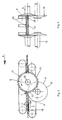
- Each cutting device comprises a disk-shaped, toothed circular knife 9 which can be driven by a motor and a counter knife 10 which cooperates therewith.
- the latter is also preferably disk-shaped and drivable. It has a circular cutting edge 11 which interacts with the cutting edges 12 of the teeth 13 one after the other, so that a batch-wise cutting process occurs.
- the axis 14 of the toothed circular knife 9 is offset in relation to the axis 15 of the counter knife 10 in the transport direction 3 or 16.
- the offset of the geometric axes corresponds to the radius of a pitch circle 17.
- the counter knife 10 is located completely below the plane of the scale 1.
- the arrangement is such that a lower band 18 or the underside of the scale 1 extends tangentially to the cutting edge 11.
- the geometric axis 19 of the knife 9 also lies approximately in the plane of the scale, in particular the upper surface of the lower belt 18, so that the pitch circle 17 of the knife 9 and the circumferential circle of the counter knife 10 intersect at least approximately at an angle of 90 °.
- the latter is preferably a toothed belt.
- an upper belt 20 lying opposite the lower belt is comparatively smooth and soft in order to be able to nestle well against the uneven contour of the scale.
- the transport device 4 also includes at least one intermediate, but in particular two intermediate belts 21.
- the lateral spacing of the belts can be changed in order to allow different widths of the scale. For this reason, the elements of the straightening station 5 and the cutting devices 7 can also be adjusted or set in the direction of the double arrows 8.
- the smallest format to be processed is decisive for the bandwidth.
- each cutting tooth 13 of the toothed circular knife 9 extends at a clearance angle 22 of approximately 0 ° to 20 °.
- the peripheral speed of the counter knife or the cutting edge 11 of the counter knife 10 corresponds approximately to the feed speed of the scale 1 at this point.
- the speed of the toothed circular knife, which has approximately the same diameter, is significantly higher, which results in a circumferential speed which is approximately 10-50 times that of the cutting edge 11.
- the two parallel upper and lower ends of the specimens 2 are trimmed.
- the scale 1 is guided over a corner by means of a suitable device 23, subsequently straightened with the aid of a second straightening station 24 and cut at a second cutting station 25.
Landscapes
- Engineering & Computer Science (AREA)
- Mechanical Engineering (AREA)
- Life Sciences & Earth Sciences (AREA)
- Forests & Forestry (AREA)
- Folding Of Thin Sheet-Like Materials, Special Discharging Devices, And Others (AREA)
- Nonmetal Cutting Devices (AREA)
Description
- Die vorliegende Erfindung bezieht sich auf eine Schneideeinrichtung mit einem Bandförderer zum Beschneiden von auf dem Bandförderer liegenden Papierbogen auf einer Seite mit einem parallel zur Förderrichtung des Bandförderers und rechtwinklig zu dessen Förderebene gelagerten, antreibbaren, kreisförmigen Messer, das im Bereich der Förderebene mit einem ebenfalls umlaufenden, kreisförmigen Gegenmesser zusammenwirkt, wobei die Achse des Gegenmessers in Förderrichtung vor jener des Messers liegt.
- Eine derartige Vorrichtung ist beispielsweise in der F-PS 2375 042 beschrieben. Der Nachteil besteht darin, dass damit nur vergleichsweise dünne Bogen bei hoher Leistung sauber geschnitten werden können. Eine wirtschaftlich annehmbare Leistung ist mit dieser Vorrichtung dann nicht mehr erreichbar, wenn die Bogen vergleichsweise dick sind, wie dies bei der Verarbeitung von Zeitschriften und derleichen der Fall ist, die nicht nur eine hohe Seitenzahl sondern zudem ein festes, zähes Papier aufweisen.
- Die vorliegende Erfindung stellt sich die Aufgabe, eine Vorrichtung der eingangs erwähnten Art derart zu verbessern, dass dicke und aus Verglaichsweise festem und zähem Papier bestehende Druckbogen mit hoher Leistung sauber geschnitten werden können.
- Erfindungsgemäss wird diese Aufgabe dadurch gelöst, dass das kreisförmige Messer gezahnt ist, und dass sein Teilkreis und der Umfangskreis des Gegenmessers sich mindestens näherungsweise unter einem Winkel von 90° schneiden.
- In der Zeichnung ist ein Ausführungsbeispiel der Erfindung dargestellt. Es zeigen:
- Figur 1 eine Draufsicht auf eine Schneideeinrichtung
- Figur 2 in vergrössertem Massstab schematisch in Ansicht eine Schneideeinrichtung
- Figur 3 eine Ansicht der Fig. 2 in Pfeilrichtung A,
- Figur 4 in vergrösserter Darstellung eine Einzelheit der Fig. 2.
- Die aus einzelnen Exemplaren 2 bestehende Schuppe 1 kommt aus einer nicht dargestellten Druckmaschine, und sie wird mit Hilfe einer Transportvorrichtung 4 in Pfeilrichtung 3 vorwärtsbewegt. Dabei gelangt sie zunächst in den Bereich einer Richtstation 5, wo ein Ausrichten der Längsränder vorgenommen wird. Nachfolgend durchläuft die Schuppe 1 eine erste Schneidestation 6. Diese besteht im wesentlichen aus zwei einander gegebüberliegenden Schneidevorrichtungen 7, welche zumindest in Richtung der Doppelpfeile 8 einstellbar sind.
- Jede Schneidvorrichtung umfasst ein scheibenförmiges, gezahntes, mittels eines Motors antreibbares Rundmesser 9 und ein damit zusammenwirkendes Gegenmesser 10. Letzteres ist vorzugsweise ebenfalls scheibenförmig und antreibbar. Es besitzt eine kreisförmige Schneide 11, die mit den Schneiden 12 der Zähne 13 nacheinander zusammenwirkt, so dass ein absatzweiser Schneidvorgang entsteht.
- Die Achse 14 des gezahnten Rundmessers 9 ist gegenüber der Achse 15 des Gegenmessers 10 in Transportrichtung 3 bzw. 16 versetzt. Der Versatz der geometrischen Achsen entspricht dem Radius eines Teilkreises 17. Ausserdem befindet sich das Gegenmesser 10 vollständig unterhalb der Ebene der Schuppe 1. Die Anordnung ist so getroffen, dass ein Unterband 18 bzw. die Unterseite der Schuppe 1 tangential zur Schneide 11 verläuft. Die geometrische Achse 19 des Messers 9 liegt ebenfalls etwa in der Ebene der Schuppe, insbesondere der oberen Fläche des Unterbands 18, sodass sich der Teilkreis 17 des Messers 9 und der Umfangskreis des Gegenmessers 10 mindestens näherungsweise unter einem Winkel von 90° schneiden. Letzteres ist in bevorzugter Weise ein Zahnriemen. Ein dem Unterband gegebüberliegendes Oberband 20 ist demgegenüber vergleichsweise glatt und weich, um sich an die unebene Kontur der Schuppe gut anschmiegen zu können. Die Transportvorrichtung 4 umfasst ausser den beiden seitlichen Ober- und Unterbändern wenigstens auch noch ein dazwischenliegendes, insbesondere aber zwei dazwischenliegende Transportbänder 21. Der Seitenabstand der Bänder ist veränderbar, um verschiedene Breiten der Schuppe zu ermöglichen. Aus diesem Grunde können auch die Elemente der Richtstation 5 und die Schneidvorrichtungen 7 im Sinne der Doppelpfeile 8 verstellt bzw. eingestellt werden. Massgebend für die Bandbreite ist das kleinste zu bearbeitende Format.
- Wie Fig. 4 zeigt, verläuft die Schneide jedes Schneidezahns 13 des gezahnten Rundmessers 9 unter einem Freiwinkel 22 von etwa 0° bis 20°. Ausserdem entspricht die Umfangsgeschwindigkeit des Gegenmessers bzw. der Schneide 11 des Gegenmessers 10 etwa der Vorschubgeschwindigkeit der Schuppe 1 an dieser Stelle. Die Drehzahl des etwa gleichen Durchmesser aufweisenden gezahnten Rundmessers ist wesentlich höher, wodurch sich eine gegenüber der Schneide 11 etwa 10-50-fache Umfangsgeschwindigkeit ergibt.
- Mit den beiden Schneidvorrichtungen 7 werden die beiden parallel verlaufenden oberen und unteren Enden der Exemplare 2 beschnitten. Um auch den gegenüber dem Heftrand liegende freien Längsrand beschneiden zu können, wird die Schuppe 1 mittels einer geeigneten Vorrichtung 23 über Eck geführt, nachfolgend mit Hilfe einer zweiten Richtstation 24 gerichtet und an einer zweiten Schneidstation 25 geschnitten. Diese umfasst lediglich eine einzige Schneidevorrichtung 7, welche mit denjenigen der ersten Schneidstation 6 identisch ist.
Claims (2)
Applications Claiming Priority (2)
| Application Number | Priority Date | Filing Date | Title |
|---|---|---|---|
| DE19792915582 DE2915582A1 (de) | 1979-04-18 | 1979-04-18 | Verfahren zum schneiden von blaettern, blattstapeln, heften o.dgl., und vorrichtung zur durchfuehrung des verfahrens |
| DE2915582 | 1979-04-18 |
Publications (2)
| Publication Number | Publication Date |
|---|---|
| EP0017878A1 EP0017878A1 (de) | 1980-10-29 |
| EP0017878B1 true EP0017878B1 (de) | 1984-07-11 |
Family
ID=6068583
Family Applications (1)
| Application Number | Title | Priority Date | Filing Date |
|---|---|---|---|
| EP19800101830 Expired EP0017878B1 (de) | 1979-04-18 | 1980-04-05 | Schneideeinrichtung für Papierbogen |
Country Status (3)
| Country | Link |
|---|---|
| EP (1) | EP0017878B1 (de) |
| JP (1) | JPS55157498A (de) |
| DE (1) | DE2915582A1 (de) |
Cited By (1)
| Publication number | Priority date | Publication date | Assignee | Title |
|---|---|---|---|---|
| EP0367715B1 (de) * | 1988-10-31 | 1993-03-17 | Ferag AG | Verfahren und Vorrichtung zum Beschneiden von Druckprodukten |
Families Citing this family (14)
| Publication number | Priority date | Publication date | Assignee | Title |
|---|---|---|---|---|
| DE3135277A1 (de) * | 1981-09-05 | 1983-03-31 | Mathias 8000 München Aigner | Rotations-schneidanlage |
| US4496140A (en) * | 1983-09-19 | 1985-01-29 | Stobb, Inc. | Apparatus for handling a signature |
| DE3401958C2 (de) * | 1984-01-20 | 1986-04-03 | Hagen 8021 Icking Gämmerler | Vorrichtung zum kontinuierlichen Trennen von übereinanderliegenden blattförmigen Gebilden |
| DE3518579A1 (de) * | 1985-05-23 | 1986-11-27 | Hagen Gaemmerler | Schneidaggregat fuer blattfoermige gebilde, insbesondere papier in schuppenform |
| CH681363A5 (de) * | 1990-04-02 | 1993-03-15 | Grapha Holding Ag | |
| US5165314A (en) * | 1990-07-24 | 1992-11-24 | Marquip, Inc. | Slitting shingled sheets |
| US5158522A (en) * | 1991-09-20 | 1992-10-27 | Marquip, Inc. | Slitting corrugated paperboard boxes |
| EP0538198B1 (de) * | 1991-10-18 | 1996-12-27 | Grapha-Holding Ag | Rotierend angetriebener Fräskopf |
| DE19620650B4 (de) * | 1996-05-22 | 2006-09-21 | Gämmerler AG | Verfahren und Vorrichtung zum Schneiden von in einem Schuppenstrom geförderten Papierprodukten |
| DE19910296A1 (de) * | 1999-03-09 | 2000-09-14 | Mathias Buhl | Vorrichtung zum Beschneiden der Längs- und Querkanten von Druckerzeugnissen |
| EP1882562B1 (de) * | 2006-07-26 | 2011-03-09 | Heidelberger Druckmaschinen Aktiengesellschaft | Bogenstanz- und -prägemaschine |
| CH704568B1 (de) * | 2007-06-15 | 2012-09-14 | Ferag Ag | Schneideinrichtung und Schneidverfahren für Druckprodukte. |
| SE533300C2 (sv) | 2008-12-15 | 2010-08-17 | Ecolean Res & Dev As | Anordning för avlägsning av en ändförslutning |
| CN112454531B (zh) * | 2020-11-19 | 2022-04-19 | 西安雄峰印刷包装有限公司 | 一种标签模切机 |
Family Cites Families (4)
| Publication number | Priority date | Publication date | Assignee | Title |
|---|---|---|---|---|
| US3153964A (en) * | 1960-05-26 | 1964-10-27 | Sun Printers Ltd | Production of magazines, pamphlets and the like |
| GB1346217A (en) * | 1971-10-12 | 1974-02-06 | Harris Intertype Corp | Book cut-off saw |
| US3813981A (en) * | 1973-06-18 | 1974-06-04 | Advance Enterprises Inc | Paper trimming knife system |
| FR2375042A1 (fr) * | 1976-12-22 | 1978-07-21 | Koenig & Bauer Ag | Procede et appareil de rognage de cahiers plies dans des rotatives d'imprimerie a bobines |
-
1979
- 1979-04-18 DE DE19792915582 patent/DE2915582A1/de not_active Withdrawn
-
1980
- 1980-04-05 EP EP19800101830 patent/EP0017878B1/de not_active Expired
- 1980-04-15 JP JP4876980A patent/JPS55157498A/ja active Pending
Cited By (1)
| Publication number | Priority date | Publication date | Assignee | Title |
|---|---|---|---|---|
| EP0367715B1 (de) * | 1988-10-31 | 1993-03-17 | Ferag AG | Verfahren und Vorrichtung zum Beschneiden von Druckprodukten |
Also Published As
| Publication number | Publication date |
|---|---|
| EP0017878A1 (de) | 1980-10-29 |
| JPS55157498A (en) | 1980-12-08 |
| DE2915582A1 (de) | 1980-10-30 |
Similar Documents
| Publication | Publication Date | Title |
|---|---|---|
| EP0017878B1 (de) | Schneideeinrichtung für Papierbogen | |
| EP0315739B1 (de) | Vorrichtung zum Trennen und Besäumen von Leiterplatten | |
| DE2916518C2 (de) | ||
| CH650967A5 (de) | Einrichtung zum seitlichen beschneiden von papierbogen. | |
| DE1511046A1 (de) | Vorrichtung zur Verarbeitung von Materialboegen | |
| EP0634325B1 (de) | Vorrichtung zum schindelartigen Anordnen von aufgeschnittenen Gütern | |
| EP1106551B1 (de) | Vorrichtung und Verfahren zum Schneiden einer Bahn | |
| EP0485790A2 (de) | Vorrichtung zum Trennen und Besäumen von Leiterplatten | |
| CH664111A5 (de) | Verfahren und anordnung zum beschneiden von signaturen. | |
| DE2752912A1 (de) | Schneidpresse zur bearbeitung plattenfoermiger, insbesondere blechfoermiger bauteile | |
| DE3030775A1 (de) | Vorrichtung zur herstellung von zumindest zweimal quergefalzten und unter erhaltung beider querfalze parallel hierzu beschnittenen produkten | |
| DE3600965C2 (de) | ||
| DE4314008C2 (de) | Verfahren und Vorrichtung zur Herstellung von Stahlfasern | |
| DE1627233C3 (de) | Fliegende Schere zum Abtrennen von Draht- oder Bandabschnitten | |
| DE2801600C3 (de) | Kreismesserschere | |
| DE3049147C2 (de) | Maschinenmesser, insbesondere kreis- oder bogenförmiger Gestalt | |
| DE717592C (de) | Maschine zum Zerschneiden von Heringen | |
| DE1207599B (de) | Furnierpaketschere | |
| DE3311824C1 (de) | Bandmesserspaltmaschine | |
| DE2458330C3 (de) | Verfahren zur Erzeugung eines sauberen Trennschnittes beim Aufteilen einer Platte aus Holz, Kunststoff o.dgl | |
| DE1994245U (de) | Filmstreifenschneid- und -stanzvorrichtung. | |
| DE3613511A1 (de) | Verfahren und vorrichtung zum beschneiden von bogenstapeln | |
| DE2146324C3 (de) | Vorrichtung zum Schneiden einer breiten Flachmaterialbahn in kleinerformatige Einzelbogen | |
| DE3009813A1 (de) | Messerwelle mit ritzern | |
| DE3911834A1 (de) | Vorrichtung zum querschneiden von materialbahnen, insbesondere von papier- oder kartonbahnen |
Legal Events
| Date | Code | Title | Description |
|---|---|---|---|
| PUAI | Public reference made under article 153(3) epc to a published international application that has entered the european phase |
Free format text: ORIGINAL CODE: 0009012 |
|
| AK | Designated contracting states |
Designated state(s): CH GB |
|
| RAP1 | Party data changed (applicant data changed or rights of an application transferred) |
Owner name: GRAPHA-HOLDING AG |
|
| 17P | Request for examination filed |
Effective date: 19810303 |
|
| GRAA | (expected) grant |
Free format text: ORIGINAL CODE: 0009210 |
|
| AK | Designated contracting states |
Designated state(s): CH GB LI |
|
| PLBE | No opposition filed within time limit |
Free format text: ORIGINAL CODE: 0009261 |
|
| STAA | Information on the status of an ep patent application or granted ep patent |
Free format text: STATUS: NO OPPOSITION FILED WITHIN TIME LIMIT |
|
| 26N | No opposition filed | ||
| PG25 | Lapsed in a contracting state [announced via postgrant information from national office to epo] |
Ref country code: CH Effective date: 19860430 Ref country code: LI Effective date: 19860430 |
|
| GBPC | Gb: european patent ceased through non-payment of renewal fee | ||
| REG | Reference to a national code |
Ref country code: CH Ref legal event code: PL |
|
| PG25 | Lapsed in a contracting state [announced via postgrant information from national office to epo] |
Ref country code: GB Effective date: 19881118 |