EP0013897B1 - Affût pour mitrailleuse légère - Google Patents
Affût pour mitrailleuse légère Download PDFInfo
- Publication number
- EP0013897B1 EP0013897B1 EP80100078A EP80100078A EP0013897B1 EP 0013897 B1 EP0013897 B1 EP 0013897B1 EP 80100078 A EP80100078 A EP 80100078A EP 80100078 A EP80100078 A EP 80100078A EP 0013897 B1 EP0013897 B1 EP 0013897B1
- Authority
- EP
- European Patent Office
- Prior art keywords
- weapon
- rotary ring
- axis
- mounting
- stop
- Prior art date
- Legal status (The legal status is an assumption and is not a legal conclusion. Google has not performed a legal analysis and makes no representation as to the accuracy of the status listed.)
- Expired
Links
- 229910000831 Steel Inorganic materials 0.000 claims description 8
- 239000010959 steel Substances 0.000 claims description 8
- 239000002184 metal Substances 0.000 claims description 3
- 230000001681 protective effect Effects 0.000 claims description 3
- 241000269400 Sirenidae Species 0.000 claims description 2
- 239000011324 bead Substances 0.000 claims 1
- 230000003028 elevating effect Effects 0.000 claims 1
- 230000008901 benefit Effects 0.000 description 5
- 230000007123 defense Effects 0.000 description 5
- 230000009471 action Effects 0.000 description 4
- 230000005540 biological transmission Effects 0.000 description 3
- 238000010304 firing Methods 0.000 description 3
- 230000008878 coupling Effects 0.000 description 2
- 238000010168 coupling process Methods 0.000 description 2
- 238000005859 coupling reaction Methods 0.000 description 2
- 230000000694 effects Effects 0.000 description 2
- 239000000463 material Substances 0.000 description 2
- 230000000149 penetrating effect Effects 0.000 description 2
- 230000001960 triggered effect Effects 0.000 description 2
- 241000721701 Lynx Species 0.000 description 1
- 230000008859 change Effects 0.000 description 1
- 238000010276 construction Methods 0.000 description 1
- 230000006735 deficit Effects 0.000 description 1
- 239000012634 fragment Substances 0.000 description 1
- 230000006872 improvement Effects 0.000 description 1
- 238000007689 inspection Methods 0.000 description 1
- 239000002085 irritant Substances 0.000 description 1
- 231100000021 irritant Toxicity 0.000 description 1
- 239000007788 liquid Substances 0.000 description 1
- 230000007246 mechanism Effects 0.000 description 1
- 238000003801 milling Methods 0.000 description 1
- 230000009467 reduction Effects 0.000 description 1
- 238000007789 sealing Methods 0.000 description 1
- 230000000007 visual effect Effects 0.000 description 1
Images

Classifications
-
- F—MECHANICAL ENGINEERING; LIGHTING; HEATING; WEAPONS; BLASTING
- F41—WEAPONS
- F41G—WEAPON SIGHTS; AIMING
- F41G1/00—Sighting devices
- F41G1/38—Telescopic sights specially adapted for smallarms or ordnance; Supports or mountings therefor
- F41G1/393—Mounting telescopic sights on ordnance; Transmission of sight movements to the associated gun
- F41G1/3935—Transmission of sight movements to the associated gun
-
- F—MECHANICAL ENGINEERING; LIGHTING; HEATING; WEAPONS; BLASTING
- F41—WEAPONS
- F41A—FUNCTIONAL FEATURES OR DETAILS COMMON TO BOTH SMALLARMS AND ORDNANCE, e.g. CANNONS; MOUNTINGS FOR SMALLARMS OR ORDNANCE
- F41A19/00—Firing or trigger mechanisms; Cocking mechanisms
- F41A19/06—Mechanical firing mechanisms, e.g. counterrecoil firing, recoil actuated firing mechanisms
- F41A19/08—Mechanical firing mechanisms, e.g. counterrecoil firing, recoil actuated firing mechanisms remote actuated; lanyard actuated
-
- F—MECHANICAL ENGINEERING; LIGHTING; HEATING; WEAPONS; BLASTING
- F41—WEAPONS
- F41A—FUNCTIONAL FEATURES OR DETAILS COMMON TO BOTH SMALLARMS AND ORDNANCE, e.g. CANNONS; MOUNTINGS FOR SMALLARMS OR ORDNANCE
- F41A27/00—Gun mountings permitting traversing or elevating movement, e.g. gun carriages
- F41A27/06—Mechanical systems
- F41A27/18—Mechanical systems for gun turrets
-
- F—MECHANICAL ENGINEERING; LIGHTING; HEATING; WEAPONS; BLASTING
- F41—WEAPONS
- F41H—ARMOUR; ARMOURED TURRETS; ARMOURED OR ARMED VEHICLES; MEANS OF ATTACK OR DEFENCE, e.g. CAMOUFLAGE, IN GENERAL
- F41H5/00—Armour; Armour plates
- F41H5/26—Peepholes; Windows; Loopholes
- F41H5/266—Periscopes for fighting or armoured vehicles
Definitions
- the invention relates to a crest mount for receiving light machine guns with an upper mount with devices for releasably fastening the weapon to a holder, with a lower mount with a rotating ring which is to be attached to a vehicle, so that the upper mount can be pivoted about a horizontal weapon pivot axis of the weapon carrier Weapon is rotatable about the vertical axis of the rotating ring, with the height and side directional levers arranged below the rotating ring, which are operatively connected to the rotating ring or the weapon holder, with a remote trigger for actuating the weapon trigger and with a rigid unit with fixed deflecting mirrors Sighting device, the view of which is below the rotating ring, the line of sight is coupled with the pivoting movement of the weapon around the pivot axis and which can be pivoted about a sight axis parallel to the weapon pivot axis, with the sighting device a further parallel to the sighting axis kachse is rigidly connected, about which a handlebar can be pivoted,
- a gun mount with a sighting device is known (US-A-2466725), but it is obvious that this known arrangement is in no way suitable for combating fast-moving targets and in particular for air defense, on the one hand because the leveling range of the weapon is too narrow and on the other hand that The mount cannot be used as a free-standing mount, although a hatch is provided for the shooter and the handlebar that makes the connection between the sighting device and the weapon easily detachable. In addition, the lateral straightening range is very limited in this known carriage.
- a crest mount for light machine guns is also known (BE-A-501 997), but because of the non-releasable connection of its 4-axis parallelogram of weapon mount and sighting device, it is not suitable as a directional mount, although the upper mount is arranged eccentrically to the rotating ring and with a man hatch is provided within the rotating ring.
- a mount for heavy weapons is also known (US-A-2 360 850), but it has neither a lower mount with a rotating ring for the lateral direction nor a 4-axis parallelogram design of the coupling between the sighting device and the weapon carrier. It is easy to see that this known carriage, which is intended for heavy machine weapons, is not suitable for use as a free-running carriage and cannot give any suggestions in this direction. However, this document shows a sighting device in which the shooter is well protected against fire.
- a gun designed as a free-running gun for light machine weapons is also known (publication on the LYNX scout tank in the magazine “Soldat undtechnik", Volume 13, March 1970, pages 132 to 133).
- this mount cannot be used as a top mount because the weapon on this mount cannot be used from inside the vehicle, because there are no corresponding active connections from inside the vehicle to the weapon, and there is no visual connection from the inside to the outside.
- the object of the present invention is seen in improving the known crest mount of the type mentioned in such a way that on the one hand it offers increased security for the shooter and on the other hand it is also suitable for defense against rapidly moving targets.
- the gun carriage according to the invention enables the shooter to open the hatch, after which the gun carriage can be used as a free-running gun carriage to combat rapidly moving targets, in particular for air defense, after loosening one end of the handlebar. With this type of application, flying targets can be fought much better and more effectively than when using a crest mount. Due to the eccentric arrangement of the top mount for The rotating ring creates space for the hatch. The shooter can take up this space comfortably because the weapon ends in the area of the weapon pivot axis and no parts of the weapon carrier or weapon protrude beyond the weapon pivot axis.
- Target markings such as crosshairs or the like
- a rear sight is attached before the sight into the sighting device and a front sight is attached.
- this has the advantage that the shooter does not have to move around if the rear sight and front sight are designed in the same way as the weapon-specific sight. Since the rear sight is easily accessible inside the vehicle, in a further embodiment it can be arranged to be adjustable and can be moved to different distances.
- the roller screen is preferably arranged relative to the other parts of the mount so that in the lowest position it is approximately flush with the surface of the lower mount. This has the advantage that it is largely protected against earth bombardment in the lowest position.
- the roller screen can be cast, for example, as a cast piece made of armored steel in order to obtain the desired bullet resistance even when bombarded with hard core bullets.
- the roller screen consists of a base body made of light metal or a similar material and a jacket, and optionally end plates made of rolled armored steel.
- This embodiment not only has the advantage of a lower weight, but also the advantage of a higher usability when fired at, because the rolled armored steel sheet poses less when fired with hard core bullets than with an armored steel cast. This property is particularly pronounced in a preferred embodiment, in which the jacket is at a distance from the base body and / or the surface of the base body facing the jacket has recessed pockets or chambers.
- the jacket can spring a little and deform inwards, which reduces throwing up on the edge of the bombardment crater, so that jamming of the diaphragm relative to the part of the lower mount facing with a small gap (due to the sealing against lead splashes) is largely ruled out.
- this design not only is there always a desired reduction in weight, but also an improvement in functional reliability when fired even with hard core bullets.
- these devices are on the one hand at the highest point of the vehicle and thus have a good effectiveness, on the other hand they are completely safe outside the firing range and can neither disturb nor be destroyed when the weapon is used.
- these additional devices are built on a protective hood, and they are supplied with power from the interior of the vehicle via cables. This embodiment is particularly advantageous if the protective hood is easily removable in order to be able to comfortably meet military operating conditions, such as for example in the case of air defense.
- the cables are therefore guided around the rotating ring and wound up in a resilient manner, and a stop is provided in each case for limiting the rotation of the rotating ring, which results in a limitation to ⁇ approximately 180 '. This creates a full turning circle and there are no blind spots.
- the cable enables reliable and interference-free transmission of the supply current of lights and turn signals as well as of speech currents or HF currents, for example to the antenna of a radio, which is also constructed as an additional device.
- the stops can be designed in different known ways. At a preferred embodiment of the invention, they are attached to the rotating ring and cooperate with fixed stop bolts.
- the stop preferably has three latching positions, and when it strikes a first stop bolt, it can be pivoted into an outer latching position in which it interacts with the second stop bolt, whereas it can be pivoted back into the middle latching position when the first stop bolt is moved back .
- the stop bolts are arranged in such a way that the first stop bolt is arranged at the end of the ⁇ 180 ° swivel range and the second stop bolt limits a certain turning by, for example, 15 ° to 30 ".
- the shooter thus has, for example, after passing through the free area ⁇ 180 ° a noticeable stop, which he can drive over until it hits the second stop pin, if necessary, so that on the one hand all needs of practical use are taken into account and on the other hand the power supply via cable is possible without any problems guided the rotating ring, and the cable end unwound from the rotating ring is wound up on a spring-driven reel or unwound from it in the opposite direction of rotation.
- the cover also covers the weapon laterally.
- the vertical front wall is preferably provided in a bulge in the hatch cover with a flap which can be actuated from the inside and through which the magazine of the weapon can be exchanged by the shooter located inside the vehicle.
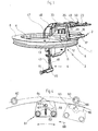
- the carriage shown in the drawing comprises a lower carriage 1 with an upper carriage 2 mounted thereon, a sighting device 3 and actuating and actuating elements 4, namely height and lateral directional levers.
- the lower mount 1 comprises a rotating ring 5, which is rotatably mounted in a counter ring 6 fixedly attached to the vehicle by means of balls 7.
- the ring is covered by a base plate 8, which protrudes outwards slightly beyond the diameter of the rotary ring 5 and whose part located within the rotary ring 5 on the one hand carries the upper mount 2, which is attached to it, and on the other hand is provided with a large cutout 9, which can be closed by a hatch cover 10, the hinge of which is located on the zone of the base plate 8 facing away from the upper mount 2.
- a receptacle 11 is attached, which is designed in the manner of a frame.
- a roller screen 12 is pivotally mounted about a sighting axis 13, which coincides with the cylinder axis of the roller screen 12 and is aligned horizontally, that is to say parallel to the plane of the rotary ring 5.
- a recess is machined into the roller cover 12, into which the sighting device 3 is inserted from below with the interposition of a seal 14.
- the sighting device 3 is constructed as a so-called angle mirror with two fixed deflecting mirrors 15 and 16.
- a grain 17 is assigned to the upper deflecting mirror 15 and is fixedly attached to the outer, radial surface of the roller screen 12.
- the lower, inner deflecting mirror 16 is assigned a rear sight 18, which is arranged in front of an inspection opening 19, which, together with the lower end of the sighting device 3, is surrounded by padding 20.
- the rear sight 18 is attached to an arm 21, which in turn is rigidly attached to the roller cover 12.
- the rear sight 18 can preferably be adjusted to different distances in a known manner.
- the arrangement of grain 17, rear sight 18 and deflecting mirror 15 and 16 is chosen so that the outer part of a line of sight 22 is parallel to a line of sight of an inserted weapon 23 '.
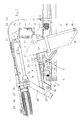
- the receptacle 11 has on its rear, facing away from the muzzle of the weapon 23 and facing the cutout 9, a tubular sleeve 24 in which a tube 25 is rotatably mounted, which is open at the top and on the lower end face a pivot 26 is provided, which is rotatably mounted in a socket 27 of the receptacle 11.
- a pivot 26 is provided, which is rotatably mounted in a socket 27 of the receptacle 11.
- an arm 28 is attached, at the free end of which there is a weapon pivot axis 29 parallel to the sighting axis 13.
- the tube 25 is fastened to the tube sleeve 24 in an easily detachable manner by means of a quick-release fastener that can be released by a lever 30.
- a groove 31 is worked into the tube 25, into which the quick-release fastener engages.
- a bearing frame 32 can be pivoted about the weapon pivot axis 29, to which the rear end of a support tube 33 is rigidly attached.
- the support tube 33 is cranked laterally at both ends so that it does not prevent the weapon 23 from being received.
- a bracket 34 is attached to the support tube 33, which carries receiving and fastening means for the easily releasable fixation of the weapon 23.
- the upper mount 2 is designed as a parallelogram.
- two arms 36 are rigidly attached to the roller cover 12, which are connected to one another at their outer end by a crossbar 37 and are additionally stiffened.
- the crossbar 37 is rotatable about a further pivot axis 38 parallel to the sighting axis 13 and the weapon pivot axis 29, which in turn is arranged at the ends of the arms 36 and is immovable relative to the arms 36.
- a link 39 can be pivoted about the pivot axis 38 and is preferably fastened, for example welded, directly to the crossbar 37.
- the end of the link 39 is pivotally connected to the support tube 33 about an axis 40 which is rigid relative to the support tube 33 and is otherwise parallel to the axes 13, 29 and 38.
- the end of the link 39 can be attached to the support tube 33 in an easily detachable manner, whereupon after this connection has been released the link can be pivoted downward about the pivot axis 38 so that it lies approximately parallel to the arms 36. In this position, the arrangement is used as a directional gun for combating flight targets in predominantly military use, the sighting device 3 not being used.
- the distance between the axes 29 and 40 is equal to the distance between the axes 38 and 13 from each other: Likewise, the distance from the axes 38 and 40 is equal to the distance between the axes 13 and 29 from each other.
- the actuating and adjusting elements 4 comprise in particular a height adjustment lever 43 which, after releasing a lock, can be pivoted upward out of the operating position shown in FIG. 1 so that it does not protrude into the vehicle interior.
- an actuating lever 45 is attached which, when it is pulled up on the handle 44 via an operative connection in the form of a linkage 46 or a Bowden cable 46 ', releases a brake against spring pressure, as a result of which the roller screen 12 is attached to it or all attached parts about the visor axis 13 is pivotable.
- the brake not shown, is engaged spring-loaded and can be released against the spring action by the actuating lever 45 and the linkage 46 or the Bowden cable 46 '.
- the brake comprises parts movable on the one hand with the roller cover 12 and parts which are fixed relative to the roller cover 12 and are fastened to the base plate 8 or the rotary ring 5. It is preferably designed as a shoe or multi-disc brake.
- a trigger is also attached to the leveling lever 43 and acts on the trigger of the weapon via a Bowden cable 47.
- the weapon can be loaded through, for example, a further Bowden cable 48.
- the Bowden cable 48 engages with an actuating hook 49 on a loading lever 50 of the weapon 23. (The Bowden cable 47 is not shown in FIG.).
- Fig. The leveling lever 43 is shown with the handle 44, but without the operating lever 45.
- an axis 71 In the vicinity of the lower end of the leveling lever 43, an axis 71, approximately parallel to the handle 44, is fastened, about which a lever 72 can be pivoted, the lower end of which projects beyond the handle 44.
- a core 74 of the Bowden cable 47 is articulated by means of a fork 75 attached to its end.
- a securing roller 76 can be pivoted about an axis 77 in three stages.
- the axis 77 runs approximately parallel to the longitudinal extension of the leveling lever 43 and approximately perpendicular to the axis 71 and radially to the length of the handle 44.
- a securing wing 78 is fastened to the securing roller 76 and serves to pivot the securing roller 76.
- the securing roller 76 At the opposite upper end of the securing roller 76, where it is located in the area of the upper arm of the lever 72, to which the core 74 of the Bowden cable 47 is articulated, the securing roller is provided with a cutout 79 as well as millings for producing stop surfaces 80 and 81.
- the stop surfaces 80, 81 or the cutout 79 can optionally be pivoted into the movement path of the upper arm of the two-armed lever 72. If the locking wing 78 and thus the locking roller 76 are in the position shown, then the two-armed lever 72 cannot be pivoted in the pull-off direction because the upper arm rests on the stop surface 81.
- the stop surface 80 is in the path of movement of the upper arm of the lever 72 and leaves a limited movement
- the trigger 73 is now actuated, the core 74 is moved forward and in turn actuates the trigger of the weapon 23, whereby a shot is triggered.
- the relevant position of the securing plate 78 is designated with an E on the handle 44. If a burst of fire is to be triggered, the trigger of the weapon 23 must be pulled further. In order to make this possible, the safety wing 78 must first be pivoted into the third position labeled F, whereby the cutout 79 of the safety roller 76 into the movement path of the upper arm of the lever 72 arrives. This allows the lever 72 to be pivoted further and thus the trigger of the weapon 23 to be pulled through until the burst of fire or continuous fire position.
- the associated position of the securing wing 78 is designated F in FIG. 7
- the Bowden cable 47 ' leads to an intermediate lever 51, which is attached to the handlebar 39' and which engages a trigger 52 of the weapon 23 ', to the trigger housing of which it is fastened by means of a quick-release fastener.
- FIG. 1 Another actuator in the form of a side straightening lever is not shown in the drawing.
- This side straightening lever is used to turn the rotary ring 5 with all the parts attached to it relative to the vehicle.
- An actuating member for releasing a spring-loaded brake is also provided on the side straightening lever, which is attached to the rotary ring 5 and engages with parts or surfaces provided on the counter ring 6 under spring action.
- the inner cylinder surface of the counter ring fixed to the vehicle can serve as a braking surface on which brake elements attached to the upper, horizontal leg of the ring 5 act.
- a trigger for the Bowden cable 47 or 47 ' On the leveling lever 43 or the handle 44 there is also a trigger for the Bowden cable 47 or 47 ', likewise not visible in the drawing, which is preferably provided with adjustable stops for limiting the movement of the trigger in order to pull the trigger 52 to different extents can, which makes it possible, when using suitable weapons, to trigger the trigger only so far that it executes the set weapon function, e.g. B. Back up, single fire, continuous fire or burst of fire.
- the inner actuating end facing the shooter can be provided with a releasable lock which makes it possible to fix the loading lever in the position in which the breech is pulled backwards is. This enables the weapon to be completely secured against unintentional firing of a shot because no shot can be released even when the trigger is actuated.
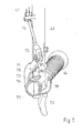
- the roller screen 12 consists of a body 53 'made of armored steel which is cast in one piece and is pivotably mounted in the receptacle 11 while maintaining a narrow gap.
- the roller cover 12 consists of a base body 53 and a jacket 54 surrounding this base body on the lateral surface and on the sides of rolled and optionally heat-treated armored steel sheet.
- the base body 53 consists of a material that is not as resistant, for example of light metal, and has a gap 69 between the jacket 54 and the base body 53.
- chambers 70 opening into the lateral surface of the base body 53 are formed in the base body 53.
- This design has the advantage that the shell 54 can deform somewhat towards the base 53 when bombarded, so that throws on the edge of the shot crater do not prevent the mobility of the roller blind 12 in the cutout of the receptacle 11. This largely prevents jamming or limiting the height range due to bombardment effects.
- a lip 55 which consists of a steel sheet and the penetrating lead, which extends tangentially to the casing 54, is attached to the underside of the base plate 8 and extends up to close to the casing 54 spreads from the point of impact, intercepts. The lead flows in because it behaves almost like a liquid when it hits it.
- the weapon 23 or 23 'can as shown in FIGS. 5 and 6, be provided with a cover 56 which can also be pivoted about the weapon pivot axis 29 and which protects the weapon against the effects of weather, dirt and also against the action of throwing anchors and stones and the like. Protects the like during police operations.
- the cover 56 also covers the magazine of the weapon.
- the hatch cover 10 is provided on its front side adjacent to the cover 56 with a flap 57 through which a magazine change can be carried out from the outside so that it is hardly visible.
- Additional devices such as loudspeaker 58 or an all-round turn signal (blue light) 59, are built on the cover for police use.
- the power supply to these units and any radio antenna provided is provided by cables routed inwards through the cover 56.
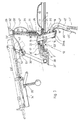
- stop bolts 60 are provided on the counter ring 6 or in some other way fixed to the vehicle.
- a latchable stop 61 is attached, which comprises a bolt 64 pivotable in a holder 62 about a pin 63.
- the bolt 64 has two arcuate stop surfaces 65 on its two opposite one another End faces and a cam 66 located therebetween and projecting radially to the axis of rotation of the rotary ring 5, in whose movement path the stop bolts 60 protrude when the rotary ring 5 is rotated when the bolt 64 is in its central latched position shown in dashed lines in FIG.
- the latching is effected by rounded recesses 67 machined into the latch 64 on the opposite side of the latch 64, into which a spring-loaded pin 69 engages, which is mounted and guided radially to the pin 63 in a bore in the holder 62.
- the bolt 64 assumes the middle position shown in dashed lines in FIG. If the rotary ring 5 is pivoted so far in the direction of an arrow 68 that the stop 61 passes the first stop bolt 60, the cam 66 runs against the stop bolt 60 and pivots the bolt 64 into the position shown in solid lines in FIG one of the two curved stop surfaces 65 faces the stop bolt 60 arranged in the direction of arrow 68. When the stop surface 65 runs against the second stop bolt 60, the rotational movement is finally limited. When moving back, the front stop pin 60 runs against the surface adjacent to the cam 66 and pivots the latch 64 back into the position shown in broken lines.
- the mount shown can be used as a universal mount for both police and military use and can be used both as a top mount and as an open mount. It is particularly advantageous that the shooter can work with the sight he is used to from using the weapon, because a mechanical rear sight and a mechanical sight can be used, which are designed in the same way as the sighting device on the weapon.
- the length of the line of sight between the rear sight and the front sight can also be measured on the weapon as well as on the mount.
- the axis parallelogram 13, 29, 38, 40 has as a fixed basis the two axes 13 and 29, about which the other two axes move accordingly, the weapon axis and the line of sight being aligned with one another.
- the angle mirror with fixed mirrors provides an inexpensive and robust sighting device that allows good battlefield observation.
- the upper mount on the tubular sleeve 24 can then be pivoted freely about the vertical axis and it can be conveniently shot out of the hatch in a position of the rotating ring in the lateral directional range of approximately 150 °. If a larger side straightening area is required, the carriage is rotated accordingly in the vehicle and then fixed again. In this mode of operation, the probability of being hit is increased compared to the previously described mode of operation.
- the invention is not limited to the exemplary embodiments shown, but deviations are possible without leaving the scope of the invention.
- individual features of the invention can be used individually or in combination.
- the upper mount 2 can comprise differently designed storage racks 32, support tubes 33 and brackets 34 with fastening means 35 and handlebars 39. which are matched to different weapons 23.
Landscapes
- Engineering & Computer Science (AREA)
- General Engineering & Computer Science (AREA)
- Physics & Mathematics (AREA)
- Optics & Photonics (AREA)
- Aiming, Guidance, Guns With A Light Source, Armor, Camouflage, And Targets (AREA)
- Telescopes (AREA)
Claims (12)
Applications Claiming Priority (2)
| Application Number | Priority Date | Filing Date | Title |
|---|---|---|---|
| DE2902992A DE2902992C3 (de) | 1979-01-26 | 1979-01-26 | Lafette zur Aufnahme leichter Maschinenwaffen mit einer Umlenkvisierung |
| DE2902992 | 1979-01-26 |
Publications (2)
| Publication Number | Publication Date |
|---|---|
| EP0013897A1 EP0013897A1 (fr) | 1980-08-06 |
| EP0013897B1 true EP0013897B1 (fr) | 1982-04-21 |
Family
ID=6061453
Family Applications (1)
| Application Number | Title | Priority Date | Filing Date |
|---|---|---|---|
| EP80100078A Expired EP0013897B1 (fr) | 1979-01-26 | 1980-01-08 | Affût pour mitrailleuse légère |
Country Status (3)
| Country | Link |
|---|---|
| US (1) | US4336743A (fr) |
| EP (1) | EP0013897B1 (fr) |
| DE (1) | DE2902992C3 (fr) |
Families Citing this family (27)
| Publication number | Priority date | Publication date | Assignee | Title |
|---|---|---|---|---|
| JPS61116107A (ja) * | 1984-11-09 | 1986-06-03 | Hitachi Ltd | アクチユエ−タの制御装置 |
| FR2593612B1 (fr) * | 1986-01-27 | 1988-05-06 | Sopelem | Dispositif de visee periscopique |
| GB8829192D0 (en) * | 1988-12-14 | 1998-03-18 | Vickers Shipbuilding & Eng | Improvements in or relating to field howitzers |
| GB2313178B (en) * | 1988-12-14 | 1998-02-18 | Vickers Shipbuilding & Eng | Improvements in or relating to field howitzers |
| FR2650385B1 (fr) * | 1989-07-31 | 1994-09-09 | Hispano Suiza Sa | Affut antiaerien leger deployable |
| FR2656683B1 (fr) * | 1989-12-28 | 1992-03-27 | Hispano Suiza Sa | Tourelle pour blinde leger equipee d'une arme laterale. |
| IL96527A (en) * | 1990-12-03 | 1995-03-30 | Israel Aircraft Ind Ltd | Machine gun apparatus |
| DE4136602A1 (de) * | 1991-11-07 | 1993-05-13 | Wegmann & Co Gmbh | Drehringlafette fuer eine leichte waffe an einem kampffahrzeug, insbesondere an einer luke eines kampfpanzers |
| US6237462B1 (en) * | 1998-05-21 | 2001-05-29 | Tactical Telepresent Technolgies, Inc. | Portable telepresent aiming system |
| US7669513B2 (en) * | 2003-10-09 | 2010-03-02 | Elbit Systems Ltd. | Multiple weapon system for armored vehicle |
| DE102004043711B4 (de) * | 2004-09-09 | 2007-05-31 | Heckler & Koch Gmbh | Freirichtlafette sowie Waffenanordnung mit einer Freirichtlafette |
| US7743543B2 (en) | 2005-10-06 | 2010-06-29 | Theodore Karagias | Trigger mechanism and a firearm containing the same |
| US7752798B2 (en) * | 2005-10-14 | 2010-07-13 | Mayerle Ronald T | See-through periscope for sighting-in optical or open sights on a firearm |
| US20070251375A1 (en) * | 2006-04-28 | 2007-11-01 | Lockheed Martin Corporation | Segmented gun turret for quick assembly |
| US7802509B2 (en) * | 2007-03-29 | 2010-09-28 | Marcus L Wall | Tactical utility pole system and method of use thereof |
| US20110072956A1 (en) * | 2007-03-29 | 2011-03-31 | Wall Marcus L | Tactical Utility Pole and Door Mount Systems and Methods of Use Thereof |
| US8109192B2 (en) * | 2009-01-28 | 2012-02-07 | Nobles Manufacturing, Inc. | Locking mount system for weapons |
| DE102009007750B3 (de) * | 2009-02-06 | 2010-07-01 | Rheinmetall Landsysteme Gmbh | Sicherheitseinrichtung einer lafetierbaren Waffe |
| US20120011963A1 (en) * | 2010-07-19 | 2012-01-19 | Burtek, Inc. | Traverse mechanism |
| FR2979425B1 (fr) * | 2011-08-29 | 2013-09-20 | Stdm | Dispositif de commande de tir deportee permettant la manipulation, en site et gisement, d'une arme. |
| US9328996B1 (en) | 2013-01-16 | 2016-05-03 | Raymond A. Lia | Bow sight having extended accuracy range |
| DE102013101635A1 (de) | 2013-02-19 | 2014-08-21 | Krauss-Maffei Wegmann Gmbh & Co. Kg | Waffenstation |
| US10371479B2 (en) * | 2013-09-11 | 2019-08-06 | Merrill Aviation, Inc. | Stabilized integrated commander's weapon station for combat armored vehicle |
| US9377255B2 (en) | 2014-02-03 | 2016-06-28 | Theodore Karagias | Multi-caliber firearms, bolt mechanisms, bolt lugs, and methods of using the same |
| ITUB20151137A1 (it) * | 2015-05-28 | 2016-11-28 | Oto Melara Spa | Sistema di supporto per arma da fuoco, in particolare destinato ad essere montato appeso ad una superficie superiore. |
| CA2999996C (fr) * | 2015-09-29 | 2019-10-22 | Russell FRANK | Systeme de tourelle coque de camping-car |
| US11067347B2 (en) | 2018-11-30 | 2021-07-20 | Theodore Karagias | Firearm bolt assembly with a pivoting handle |
Family Cites Families (16)
| Publication number | Priority date | Publication date | Assignee | Title |
|---|---|---|---|---|
| FR742421A (fr) * | 1933-03-07 | |||
| BE501997A (fr) * | ||||
| GB112058A (en) * | 1917-01-16 | 1917-12-27 | Periscopes And Hyposcopes Ltd | Improvements in Means for Sighting and Manipulating Guns from Cover. |
| FR34678E (fr) * | 1926-12-09 | 1929-09-19 | ||
| US2085024A (en) * | 1933-01-05 | 1937-06-29 | Greenhow Maury Jr | Machine gun mount |
| US2383487A (en) * | 1941-03-13 | 1945-08-28 | Melvin M Johnson | Automatic gun |
| US2390516A (en) * | 1941-07-11 | 1945-12-11 | David J Crawford | Gun sight mounting |
| US2441874A (en) * | 1942-02-24 | 1948-05-18 | Harold W Evans | Gun mount for land and water vehicles |
| US2458956A (en) * | 1942-06-26 | 1949-01-11 | Motley Lewis | Gun mounting |
| US2360850A (en) * | 1942-07-01 | 1944-10-24 | Joseph M Colby | Gun mount |
| US2466725A (en) * | 1945-05-22 | 1949-04-12 | Marvin J Minter | Vehicle mounted gun and periscope mounting therefor |
| FR1234832A (fr) * | 1959-05-21 | 1960-10-19 | Anciens Etablissements Panhard | Perfectionnements apportés aux moyens optiques de pointage des armes en tourelles |
| DE1196098B (de) * | 1963-12-05 | 1965-07-01 | Walter Ruf Dipl Ing | Halterung fuer leichte Waffen mit einem Zielfernrohr |
| CH494940A (de) * | 1966-06-24 | 1970-08-15 | Walter Dipl Ing Ruf | Panzerfahrzeug mit einer Vorrichtung zur Halterung einer leichten Waffe auf dem Dach |
| US3424052A (en) * | 1966-07-21 | 1969-01-28 | Walter Ruf | Mount for light guns |
| US3854377A (en) * | 1972-05-20 | 1974-12-17 | Keller & Knappich Augsburg | Tank turret for automatic weapons |
-
1979
- 1979-01-26 DE DE2902992A patent/DE2902992C3/de not_active Expired
-
1980
- 1980-01-08 EP EP80100078A patent/EP0013897B1/fr not_active Expired
- 1980-01-10 US US06/110,909 patent/US4336743A/en not_active Expired - Lifetime
Also Published As
| Publication number | Publication date |
|---|---|
| US4336743A (en) | 1982-06-29 |
| DE2902992B2 (de) | 1980-11-13 |
| DE2902992C3 (de) | 1981-09-24 |
| DE2902992A1 (de) | 1980-07-31 |
| EP0013897A1 (fr) | 1980-08-06 |
Similar Documents
| Publication | Publication Date | Title |
|---|---|---|
| EP0013897B1 (fr) | Affût pour mitrailleuse légère | |
| EP1102957B1 (fr) | Lance-grenades rapporte | |
| DE60210182T2 (de) | Mit zwei Waffen versehener Turm für ein militärisches Kampffahrzeug | |
| EP1557634A1 (fr) | Dispositif pour le support d'une plate-forme d'armes | |
| EP0152797B1 (fr) | Arme de poing | |
| EP1557633A1 (fr) | Dispositif pour le montage et la retenue d'un poste d'armement | |
| DE19736948C1 (de) | Schwenklafette für eine Feuerwaffe wie z.B. ein Maschinengewehr | |
| EP0378157B1 (fr) | Véhicule de combat avec des plate-formes de combat et élévateur | |
| DE3108132C2 (de) | Lafette für gepanzerte Objekte zum Aufnehmen von Handfeuerwaffen | |
| EP0388762B1 (fr) | Module d'armes pour chars de bataille | |
| EP0844455B1 (fr) | Dispositif de montage d'un canon dans une tourelle blindée | |
| DE946601C (de) | Panzerfahrzeug | |
| DE1081352B (de) | Handfeuerwaffe zum Schiessen aus seitlicher Deckung | |
| DE3524244A1 (de) | Gepanzertes ketten- oder radkampffahrzeug | |
| EP0892237A1 (fr) | Arme à feu automatique | |
| DE7813857U1 (de) | Gepanzerter und um eine vertikale achse schwenkbarer fahrzeugturm | |
| CH494940A (de) | Panzerfahrzeug mit einer Vorrichtung zur Halterung einer leichten Waffe auf dem Dach | |
| AT396991B (de) | Geschosswaffe, insbesondere granatwerfer | |
| EP0134775B1 (fr) | Mortier | |
| DE19857755C2 (de) | Verschwenkbare Visiereinrichtung | |
| DE660803C (de) | Vorrichtung zum Auswerfen von Granaten, welche aus einem vorn eine Granate aufnehmenden, hinten einen Anschlagteil aufweisenden Rohr mit einer an ihm loesbar befestigtenKleinhandfeuerwaffe besteht | |
| DE1945141U (de) | Halterung fuer waffen. | |
| DE2406099A1 (de) | Militaerische einrichtung | |
| DE2064133C3 (de) | Lafette zur Installation von leichten Maschinenwaffen | |
| DEE0007959MA (fr) |
Legal Events
| Date | Code | Title | Description |
|---|---|---|---|
| PUAI | Public reference made under article 153(3) epc to a published international application that has entered the european phase |
Free format text: ORIGINAL CODE: 0009012 |
|
| AK | Designated contracting states |
Designated state(s): BE CH FR GB IT NL SE |
|
| 17P | Request for examination filed | ||
| ITF | It: translation for a ep patent filed |
Owner name: STUDIO TORTA SOCIETA' SEMPLICE |
|
| GRAA | (expected) grant |
Free format text: ORIGINAL CODE: 0009210 |
|
| AK | Designated contracting states |
Designated state(s): BE CH FR GB IT NL SE |
|
| PGFP | Annual fee paid to national office [announced via postgrant information from national office to epo] |
Ref country code: SE Payment date: 19831231 Year of fee payment: 5 |
|
| PGFP | Annual fee paid to national office [announced via postgrant information from national office to epo] |
Ref country code: FR Payment date: 19840112 Year of fee payment: 5 |
|
| PGFP | Annual fee paid to national office [announced via postgrant information from national office to epo] |
Ref country code: CH Payment date: 19840330 Year of fee payment: 5 |
|
| PGFP | Annual fee paid to national office [announced via postgrant information from national office to epo] |
Ref country code: BE Payment date: 19841231 Year of fee payment: 6 |
|
| REG | Reference to a national code |
Ref country code: FR Ref legal event code: ST |
|
| PGFP | Annual fee paid to national office [announced via postgrant information from national office to epo] |
Ref country code: NL Payment date: 19860131 Year of fee payment: 7 |
|
| REG | Reference to a national code |
Ref country code: FR Ref legal event code: DA |
|
| PG25 | Lapsed in a contracting state [announced via postgrant information from national office to epo] |
Ref country code: SE Effective date: 19870109 |
|
| PG25 | Lapsed in a contracting state [announced via postgrant information from national office to epo] |
Ref country code: CH Effective date: 19870131 |
|
| BERE | Be: lapsed |
Owner name: HECKLER & KOCH G.M.B.H. Effective date: 19870131 |
|
| PG25 | Lapsed in a contracting state [announced via postgrant information from national office to epo] |
Ref country code: NL Effective date: 19870801 |
|
| GBPC | Gb: european patent ceased through non-payment of renewal fee | ||
| NLV4 | Nl: lapsed or anulled due to non-payment of the annual fee | ||
| PG25 | Lapsed in a contracting state [announced via postgrant information from national office to epo] |
Ref country code: FR Free format text: LAPSE BECAUSE OF NON-PAYMENT OF DUE FEES Effective date: 19870930 |
|
| REG | Reference to a national code |
Ref country code: CH Ref legal event code: PL |
|
| REG | Reference to a national code |
Ref country code: FR Ref legal event code: ST |
|
| PG25 | Lapsed in a contracting state [announced via postgrant information from national office to epo] |
Ref country code: GB Effective date: 19881118 |
|
| PG25 | Lapsed in a contracting state [announced via postgrant information from national office to epo] |
Ref country code: BE Effective date: 19890131 |
|
| EUG | Se: european patent has lapsed |
Ref document number: 80100078.7 Effective date: 19870923 |
|
| PLBE | No opposition filed within time limit |
Free format text: ORIGINAL CODE: 0009261 |
|
| STAA | Information on the status of an ep patent application or granted ep patent |
Free format text: STATUS: NO OPPOSITION FILED WITHIN TIME LIMIT |