EP0013897B1 - Machine-gun mounting - Google Patents
Machine-gun mounting Download PDFInfo
- Publication number
- EP0013897B1 EP0013897B1 EP80100078A EP80100078A EP0013897B1 EP 0013897 B1 EP0013897 B1 EP 0013897B1 EP 80100078 A EP80100078 A EP 80100078A EP 80100078 A EP80100078 A EP 80100078A EP 0013897 B1 EP0013897 B1 EP 0013897B1
- Authority
- EP
- European Patent Office
- Prior art keywords
- weapon
- rotary ring
- axis
- mounting
- stop
- Prior art date
- Legal status (The legal status is an assumption and is not a legal conclusion. Google has not performed a legal analysis and makes no representation as to the accuracy of the status listed.)
- Expired
Links
- 229910000831 Steel Inorganic materials 0.000 claims description 8
- 239000010959 steel Substances 0.000 claims description 8
- 239000002184 metal Substances 0.000 claims description 3
- 230000001681 protective effect Effects 0.000 claims description 3
- 241000269400 Sirenidae Species 0.000 claims description 2
- 239000011324 bead Substances 0.000 claims 1
- 230000003028 elevating effect Effects 0.000 claims 1
- 230000008901 benefit Effects 0.000 description 5
- 230000007123 defense Effects 0.000 description 5
- 230000009471 action Effects 0.000 description 4
- 230000005540 biological transmission Effects 0.000 description 3
- 238000010304 firing Methods 0.000 description 3
- 230000008878 coupling Effects 0.000 description 2
- 238000010168 coupling process Methods 0.000 description 2
- 238000005859 coupling reaction Methods 0.000 description 2
- 230000000694 effects Effects 0.000 description 2
- 239000000463 material Substances 0.000 description 2
- 230000000149 penetrating effect Effects 0.000 description 2
- 230000001960 triggered effect Effects 0.000 description 2
- 241000721701 Lynx Species 0.000 description 1
- 230000008859 change Effects 0.000 description 1
- 238000010276 construction Methods 0.000 description 1
- 230000006735 deficit Effects 0.000 description 1
- 239000012634 fragment Substances 0.000 description 1
- 230000006872 improvement Effects 0.000 description 1
- 238000007689 inspection Methods 0.000 description 1
- 239000002085 irritant Substances 0.000 description 1
- 231100000021 irritant Toxicity 0.000 description 1
- 239000007788 liquid Substances 0.000 description 1
- 230000007246 mechanism Effects 0.000 description 1
- 238000003801 milling Methods 0.000 description 1
- 230000009467 reduction Effects 0.000 description 1
- 238000007789 sealing Methods 0.000 description 1
- 230000000007 visual effect Effects 0.000 description 1
Images

Classifications
-
- F—MECHANICAL ENGINEERING; LIGHTING; HEATING; WEAPONS; BLASTING
- F41—WEAPONS
- F41G—WEAPON SIGHTS; AIMING
- F41G1/00—Sighting devices
- F41G1/38—Telescopic sights specially adapted for smallarms or ordnance; Supports or mountings therefor
- F41G1/393—Mounting telescopic sights on ordnance; Transmission of sight movements to the associated gun
- F41G1/3935—Transmission of sight movements to the associated gun
-
- F—MECHANICAL ENGINEERING; LIGHTING; HEATING; WEAPONS; BLASTING
- F41—WEAPONS
- F41A—FUNCTIONAL FEATURES OR DETAILS COMMON TO BOTH SMALLARMS AND ORDNANCE, e.g. CANNONS; MOUNTINGS FOR SMALLARMS OR ORDNANCE
- F41A19/00—Firing or trigger mechanisms; Cocking mechanisms
- F41A19/06—Mechanical firing mechanisms, e.g. counterrecoil firing, recoil actuated firing mechanisms
- F41A19/08—Mechanical firing mechanisms, e.g. counterrecoil firing, recoil actuated firing mechanisms remote actuated; lanyard actuated
-
- F—MECHANICAL ENGINEERING; LIGHTING; HEATING; WEAPONS; BLASTING
- F41—WEAPONS
- F41A—FUNCTIONAL FEATURES OR DETAILS COMMON TO BOTH SMALLARMS AND ORDNANCE, e.g. CANNONS; MOUNTINGS FOR SMALLARMS OR ORDNANCE
- F41A27/00—Gun mountings permitting traversing or elevating movement, e.g. gun carriages
- F41A27/06—Mechanical systems
- F41A27/18—Mechanical systems for gun turrets
-
- F—MECHANICAL ENGINEERING; LIGHTING; HEATING; WEAPONS; BLASTING
- F41—WEAPONS
- F41H—ARMOUR; ARMOURED TURRETS; ARMOURED OR ARMED VEHICLES; MEANS OF ATTACK OR DEFENCE, e.g. CAMOUFLAGE, IN GENERAL
- F41H5/00—Armour; Armour plates
- F41H5/26—Peepholes; Windows; Loopholes
- F41H5/266—Periscopes for fighting or armoured vehicles
Definitions
- the invention relates to a crest mount for receiving light machine guns with an upper mount with devices for releasably fastening the weapon to a holder, with a lower mount with a rotating ring which is to be attached to a vehicle, so that the upper mount can be pivoted about a horizontal weapon pivot axis of the weapon carrier Weapon is rotatable about the vertical axis of the rotating ring, with the height and side directional levers arranged below the rotating ring, which are operatively connected to the rotating ring or the weapon holder, with a remote trigger for actuating the weapon trigger and with a rigid unit with fixed deflecting mirrors Sighting device, the view of which is below the rotating ring, the line of sight is coupled with the pivoting movement of the weapon around the pivot axis and which can be pivoted about a sight axis parallel to the weapon pivot axis, with the sighting device a further parallel to the sighting axis kachse is rigidly connected, about which a handlebar can be pivoted,
- a gun mount with a sighting device is known (US-A-2466725), but it is obvious that this known arrangement is in no way suitable for combating fast-moving targets and in particular for air defense, on the one hand because the leveling range of the weapon is too narrow and on the other hand that The mount cannot be used as a free-standing mount, although a hatch is provided for the shooter and the handlebar that makes the connection between the sighting device and the weapon easily detachable. In addition, the lateral straightening range is very limited in this known carriage.
- a crest mount for light machine guns is also known (BE-A-501 997), but because of the non-releasable connection of its 4-axis parallelogram of weapon mount and sighting device, it is not suitable as a directional mount, although the upper mount is arranged eccentrically to the rotating ring and with a man hatch is provided within the rotating ring.
- a mount for heavy weapons is also known (US-A-2 360 850), but it has neither a lower mount with a rotating ring for the lateral direction nor a 4-axis parallelogram design of the coupling between the sighting device and the weapon carrier. It is easy to see that this known carriage, which is intended for heavy machine weapons, is not suitable for use as a free-running carriage and cannot give any suggestions in this direction. However, this document shows a sighting device in which the shooter is well protected against fire.
- a gun designed as a free-running gun for light machine weapons is also known (publication on the LYNX scout tank in the magazine “Soldat undtechnik", Volume 13, March 1970, pages 132 to 133).
- this mount cannot be used as a top mount because the weapon on this mount cannot be used from inside the vehicle, because there are no corresponding active connections from inside the vehicle to the weapon, and there is no visual connection from the inside to the outside.
- the object of the present invention is seen in improving the known crest mount of the type mentioned in such a way that on the one hand it offers increased security for the shooter and on the other hand it is also suitable for defense against rapidly moving targets.
- the gun carriage according to the invention enables the shooter to open the hatch, after which the gun carriage can be used as a free-running gun carriage to combat rapidly moving targets, in particular for air defense, after loosening one end of the handlebar. With this type of application, flying targets can be fought much better and more effectively than when using a crest mount. Due to the eccentric arrangement of the top mount for The rotating ring creates space for the hatch. The shooter can take up this space comfortably because the weapon ends in the area of the weapon pivot axis and no parts of the weapon carrier or weapon protrude beyond the weapon pivot axis.
- Target markings such as crosshairs or the like
- a rear sight is attached before the sight into the sighting device and a front sight is attached.
- this has the advantage that the shooter does not have to move around if the rear sight and front sight are designed in the same way as the weapon-specific sight. Since the rear sight is easily accessible inside the vehicle, in a further embodiment it can be arranged to be adjustable and can be moved to different distances.
- the roller screen is preferably arranged relative to the other parts of the mount so that in the lowest position it is approximately flush with the surface of the lower mount. This has the advantage that it is largely protected against earth bombardment in the lowest position.
- the roller screen can be cast, for example, as a cast piece made of armored steel in order to obtain the desired bullet resistance even when bombarded with hard core bullets.
- the roller screen consists of a base body made of light metal or a similar material and a jacket, and optionally end plates made of rolled armored steel.
- This embodiment not only has the advantage of a lower weight, but also the advantage of a higher usability when fired at, because the rolled armored steel sheet poses less when fired with hard core bullets than with an armored steel cast. This property is particularly pronounced in a preferred embodiment, in which the jacket is at a distance from the base body and / or the surface of the base body facing the jacket has recessed pockets or chambers.
- the jacket can spring a little and deform inwards, which reduces throwing up on the edge of the bombardment crater, so that jamming of the diaphragm relative to the part of the lower mount facing with a small gap (due to the sealing against lead splashes) is largely ruled out.
- this design not only is there always a desired reduction in weight, but also an improvement in functional reliability when fired even with hard core bullets.
- these devices are on the one hand at the highest point of the vehicle and thus have a good effectiveness, on the other hand they are completely safe outside the firing range and can neither disturb nor be destroyed when the weapon is used.
- these additional devices are built on a protective hood, and they are supplied with power from the interior of the vehicle via cables. This embodiment is particularly advantageous if the protective hood is easily removable in order to be able to comfortably meet military operating conditions, such as for example in the case of air defense.
- the cables are therefore guided around the rotating ring and wound up in a resilient manner, and a stop is provided in each case for limiting the rotation of the rotating ring, which results in a limitation to ⁇ approximately 180 '. This creates a full turning circle and there are no blind spots.
- the cable enables reliable and interference-free transmission of the supply current of lights and turn signals as well as of speech currents or HF currents, for example to the antenna of a radio, which is also constructed as an additional device.
- the stops can be designed in different known ways. At a preferred embodiment of the invention, they are attached to the rotating ring and cooperate with fixed stop bolts.
- the stop preferably has three latching positions, and when it strikes a first stop bolt, it can be pivoted into an outer latching position in which it interacts with the second stop bolt, whereas it can be pivoted back into the middle latching position when the first stop bolt is moved back .
- the stop bolts are arranged in such a way that the first stop bolt is arranged at the end of the ⁇ 180 ° swivel range and the second stop bolt limits a certain turning by, for example, 15 ° to 30 ".
- the shooter thus has, for example, after passing through the free area ⁇ 180 ° a noticeable stop, which he can drive over until it hits the second stop pin, if necessary, so that on the one hand all needs of practical use are taken into account and on the other hand the power supply via cable is possible without any problems guided the rotating ring, and the cable end unwound from the rotating ring is wound up on a spring-driven reel or unwound from it in the opposite direction of rotation.
- the cover also covers the weapon laterally.
- the vertical front wall is preferably provided in a bulge in the hatch cover with a flap which can be actuated from the inside and through which the magazine of the weapon can be exchanged by the shooter located inside the vehicle.
- the carriage shown in the drawing comprises a lower carriage 1 with an upper carriage 2 mounted thereon, a sighting device 3 and actuating and actuating elements 4, namely height and lateral directional levers.
- the lower mount 1 comprises a rotating ring 5, which is rotatably mounted in a counter ring 6 fixedly attached to the vehicle by means of balls 7.
- the ring is covered by a base plate 8, which protrudes outwards slightly beyond the diameter of the rotary ring 5 and whose part located within the rotary ring 5 on the one hand carries the upper mount 2, which is attached to it, and on the other hand is provided with a large cutout 9, which can be closed by a hatch cover 10, the hinge of which is located on the zone of the base plate 8 facing away from the upper mount 2.
- a receptacle 11 is attached, which is designed in the manner of a frame.
- a roller screen 12 is pivotally mounted about a sighting axis 13, which coincides with the cylinder axis of the roller screen 12 and is aligned horizontally, that is to say parallel to the plane of the rotary ring 5.
- a recess is machined into the roller cover 12, into which the sighting device 3 is inserted from below with the interposition of a seal 14.
- the sighting device 3 is constructed as a so-called angle mirror with two fixed deflecting mirrors 15 and 16.
- a grain 17 is assigned to the upper deflecting mirror 15 and is fixedly attached to the outer, radial surface of the roller screen 12.
- the lower, inner deflecting mirror 16 is assigned a rear sight 18, which is arranged in front of an inspection opening 19, which, together with the lower end of the sighting device 3, is surrounded by padding 20.
- the rear sight 18 is attached to an arm 21, which in turn is rigidly attached to the roller cover 12.
- the rear sight 18 can preferably be adjusted to different distances in a known manner.
- the arrangement of grain 17, rear sight 18 and deflecting mirror 15 and 16 is chosen so that the outer part of a line of sight 22 is parallel to a line of sight of an inserted weapon 23 '.
- the receptacle 11 has on its rear, facing away from the muzzle of the weapon 23 and facing the cutout 9, a tubular sleeve 24 in which a tube 25 is rotatably mounted, which is open at the top and on the lower end face a pivot 26 is provided, which is rotatably mounted in a socket 27 of the receptacle 11.
- a pivot 26 is provided, which is rotatably mounted in a socket 27 of the receptacle 11.
- an arm 28 is attached, at the free end of which there is a weapon pivot axis 29 parallel to the sighting axis 13.
- the tube 25 is fastened to the tube sleeve 24 in an easily detachable manner by means of a quick-release fastener that can be released by a lever 30.
- a groove 31 is worked into the tube 25, into which the quick-release fastener engages.
- a bearing frame 32 can be pivoted about the weapon pivot axis 29, to which the rear end of a support tube 33 is rigidly attached.
- the support tube 33 is cranked laterally at both ends so that it does not prevent the weapon 23 from being received.
- a bracket 34 is attached to the support tube 33, which carries receiving and fastening means for the easily releasable fixation of the weapon 23.
- the upper mount 2 is designed as a parallelogram.
- two arms 36 are rigidly attached to the roller cover 12, which are connected to one another at their outer end by a crossbar 37 and are additionally stiffened.
- the crossbar 37 is rotatable about a further pivot axis 38 parallel to the sighting axis 13 and the weapon pivot axis 29, which in turn is arranged at the ends of the arms 36 and is immovable relative to the arms 36.
- a link 39 can be pivoted about the pivot axis 38 and is preferably fastened, for example welded, directly to the crossbar 37.
- the end of the link 39 is pivotally connected to the support tube 33 about an axis 40 which is rigid relative to the support tube 33 and is otherwise parallel to the axes 13, 29 and 38.
- the end of the link 39 can be attached to the support tube 33 in an easily detachable manner, whereupon after this connection has been released the link can be pivoted downward about the pivot axis 38 so that it lies approximately parallel to the arms 36. In this position, the arrangement is used as a directional gun for combating flight targets in predominantly military use, the sighting device 3 not being used.
- the distance between the axes 29 and 40 is equal to the distance between the axes 38 and 13 from each other: Likewise, the distance from the axes 38 and 40 is equal to the distance between the axes 13 and 29 from each other.
- the actuating and adjusting elements 4 comprise in particular a height adjustment lever 43 which, after releasing a lock, can be pivoted upward out of the operating position shown in FIG. 1 so that it does not protrude into the vehicle interior.
- an actuating lever 45 is attached which, when it is pulled up on the handle 44 via an operative connection in the form of a linkage 46 or a Bowden cable 46 ', releases a brake against spring pressure, as a result of which the roller screen 12 is attached to it or all attached parts about the visor axis 13 is pivotable.
- the brake not shown, is engaged spring-loaded and can be released against the spring action by the actuating lever 45 and the linkage 46 or the Bowden cable 46 '.
- the brake comprises parts movable on the one hand with the roller cover 12 and parts which are fixed relative to the roller cover 12 and are fastened to the base plate 8 or the rotary ring 5. It is preferably designed as a shoe or multi-disc brake.
- a trigger is also attached to the leveling lever 43 and acts on the trigger of the weapon via a Bowden cable 47.
- the weapon can be loaded through, for example, a further Bowden cable 48.
- the Bowden cable 48 engages with an actuating hook 49 on a loading lever 50 of the weapon 23. (The Bowden cable 47 is not shown in FIG.).
- Fig. The leveling lever 43 is shown with the handle 44, but without the operating lever 45.
- an axis 71 In the vicinity of the lower end of the leveling lever 43, an axis 71, approximately parallel to the handle 44, is fastened, about which a lever 72 can be pivoted, the lower end of which projects beyond the handle 44.
- a core 74 of the Bowden cable 47 is articulated by means of a fork 75 attached to its end.
- a securing roller 76 can be pivoted about an axis 77 in three stages.
- the axis 77 runs approximately parallel to the longitudinal extension of the leveling lever 43 and approximately perpendicular to the axis 71 and radially to the length of the handle 44.
- a securing wing 78 is fastened to the securing roller 76 and serves to pivot the securing roller 76.
- the securing roller 76 At the opposite upper end of the securing roller 76, where it is located in the area of the upper arm of the lever 72, to which the core 74 of the Bowden cable 47 is articulated, the securing roller is provided with a cutout 79 as well as millings for producing stop surfaces 80 and 81.
- the stop surfaces 80, 81 or the cutout 79 can optionally be pivoted into the movement path of the upper arm of the two-armed lever 72. If the locking wing 78 and thus the locking roller 76 are in the position shown, then the two-armed lever 72 cannot be pivoted in the pull-off direction because the upper arm rests on the stop surface 81.
- the stop surface 80 is in the path of movement of the upper arm of the lever 72 and leaves a limited movement
- the trigger 73 is now actuated, the core 74 is moved forward and in turn actuates the trigger of the weapon 23, whereby a shot is triggered.
- the relevant position of the securing plate 78 is designated with an E on the handle 44. If a burst of fire is to be triggered, the trigger of the weapon 23 must be pulled further. In order to make this possible, the safety wing 78 must first be pivoted into the third position labeled F, whereby the cutout 79 of the safety roller 76 into the movement path of the upper arm of the lever 72 arrives. This allows the lever 72 to be pivoted further and thus the trigger of the weapon 23 to be pulled through until the burst of fire or continuous fire position.
- the associated position of the securing wing 78 is designated F in FIG. 7
- the Bowden cable 47 ' leads to an intermediate lever 51, which is attached to the handlebar 39' and which engages a trigger 52 of the weapon 23 ', to the trigger housing of which it is fastened by means of a quick-release fastener.
- FIG. 1 Another actuator in the form of a side straightening lever is not shown in the drawing.
- This side straightening lever is used to turn the rotary ring 5 with all the parts attached to it relative to the vehicle.
- An actuating member for releasing a spring-loaded brake is also provided on the side straightening lever, which is attached to the rotary ring 5 and engages with parts or surfaces provided on the counter ring 6 under spring action.
- the inner cylinder surface of the counter ring fixed to the vehicle can serve as a braking surface on which brake elements attached to the upper, horizontal leg of the ring 5 act.
- a trigger for the Bowden cable 47 or 47 ' On the leveling lever 43 or the handle 44 there is also a trigger for the Bowden cable 47 or 47 ', likewise not visible in the drawing, which is preferably provided with adjustable stops for limiting the movement of the trigger in order to pull the trigger 52 to different extents can, which makes it possible, when using suitable weapons, to trigger the trigger only so far that it executes the set weapon function, e.g. B. Back up, single fire, continuous fire or burst of fire.
- the inner actuating end facing the shooter can be provided with a releasable lock which makes it possible to fix the loading lever in the position in which the breech is pulled backwards is. This enables the weapon to be completely secured against unintentional firing of a shot because no shot can be released even when the trigger is actuated.
- the roller screen 12 consists of a body 53 'made of armored steel which is cast in one piece and is pivotably mounted in the receptacle 11 while maintaining a narrow gap.
- the roller cover 12 consists of a base body 53 and a jacket 54 surrounding this base body on the lateral surface and on the sides of rolled and optionally heat-treated armored steel sheet.
- the base body 53 consists of a material that is not as resistant, for example of light metal, and has a gap 69 between the jacket 54 and the base body 53.
- chambers 70 opening into the lateral surface of the base body 53 are formed in the base body 53.
- This design has the advantage that the shell 54 can deform somewhat towards the base 53 when bombarded, so that throws on the edge of the shot crater do not prevent the mobility of the roller blind 12 in the cutout of the receptacle 11. This largely prevents jamming or limiting the height range due to bombardment effects.
- a lip 55 which consists of a steel sheet and the penetrating lead, which extends tangentially to the casing 54, is attached to the underside of the base plate 8 and extends up to close to the casing 54 spreads from the point of impact, intercepts. The lead flows in because it behaves almost like a liquid when it hits it.
- the weapon 23 or 23 'can as shown in FIGS. 5 and 6, be provided with a cover 56 which can also be pivoted about the weapon pivot axis 29 and which protects the weapon against the effects of weather, dirt and also against the action of throwing anchors and stones and the like. Protects the like during police operations.
- the cover 56 also covers the magazine of the weapon.
- the hatch cover 10 is provided on its front side adjacent to the cover 56 with a flap 57 through which a magazine change can be carried out from the outside so that it is hardly visible.
- Additional devices such as loudspeaker 58 or an all-round turn signal (blue light) 59, are built on the cover for police use.
- the power supply to these units and any radio antenna provided is provided by cables routed inwards through the cover 56.
- stop bolts 60 are provided on the counter ring 6 or in some other way fixed to the vehicle.
- a latchable stop 61 is attached, which comprises a bolt 64 pivotable in a holder 62 about a pin 63.
- the bolt 64 has two arcuate stop surfaces 65 on its two opposite one another End faces and a cam 66 located therebetween and projecting radially to the axis of rotation of the rotary ring 5, in whose movement path the stop bolts 60 protrude when the rotary ring 5 is rotated when the bolt 64 is in its central latched position shown in dashed lines in FIG.
- the latching is effected by rounded recesses 67 machined into the latch 64 on the opposite side of the latch 64, into which a spring-loaded pin 69 engages, which is mounted and guided radially to the pin 63 in a bore in the holder 62.
- the bolt 64 assumes the middle position shown in dashed lines in FIG. If the rotary ring 5 is pivoted so far in the direction of an arrow 68 that the stop 61 passes the first stop bolt 60, the cam 66 runs against the stop bolt 60 and pivots the bolt 64 into the position shown in solid lines in FIG one of the two curved stop surfaces 65 faces the stop bolt 60 arranged in the direction of arrow 68. When the stop surface 65 runs against the second stop bolt 60, the rotational movement is finally limited. When moving back, the front stop pin 60 runs against the surface adjacent to the cam 66 and pivots the latch 64 back into the position shown in broken lines.
- the mount shown can be used as a universal mount for both police and military use and can be used both as a top mount and as an open mount. It is particularly advantageous that the shooter can work with the sight he is used to from using the weapon, because a mechanical rear sight and a mechanical sight can be used, which are designed in the same way as the sighting device on the weapon.
- the length of the line of sight between the rear sight and the front sight can also be measured on the weapon as well as on the mount.
- the axis parallelogram 13, 29, 38, 40 has as a fixed basis the two axes 13 and 29, about which the other two axes move accordingly, the weapon axis and the line of sight being aligned with one another.
- the angle mirror with fixed mirrors provides an inexpensive and robust sighting device that allows good battlefield observation.
- the upper mount on the tubular sleeve 24 can then be pivoted freely about the vertical axis and it can be conveniently shot out of the hatch in a position of the rotating ring in the lateral directional range of approximately 150 °. If a larger side straightening area is required, the carriage is rotated accordingly in the vehicle and then fixed again. In this mode of operation, the probability of being hit is increased compared to the previously described mode of operation.
- the invention is not limited to the exemplary embodiments shown, but deviations are possible without leaving the scope of the invention.
- individual features of the invention can be used individually or in combination.
- the upper mount 2 can comprise differently designed storage racks 32, support tubes 33 and brackets 34 with fastening means 35 and handlebars 39. which are matched to different weapons 23.
Description
Die Erfindung betrifft eine Scheitellafette zur Aufnahme leichter Maschinenwaffen mit einer Oberlafette mit Vorrichtungen zum lösbaren Befestigen der Waffe an einer Halterung, mit einer Unterlafette mit einem Drehring, der an einem Fahrzeug anzubringen ist, so daß die Oberlafette mit der um eine horizontale Waffenschwenkachse des Waffenträgers schwenkbaren Waffe um die vertikale Achse des Drehringes drehbar ist, mit unterhalb des Drehringes angeordnetem Höhen- und Seitenrichthebel, die mit dem Drehring bzw. der Waffenhalterung wirkverbunden sind, mit einem Fernabzug zum Betätigen des Waffenabzuges und mit einer als in sich starren Einheit mit festen Umlenkspiegeln aufgebauten Visiereinrichtung, deren Einblick sich unterhalb des Drehringes befindet, deren Visierlinie mit der Schwenkbewegung der Waffe um die Schwenkachse gekoppelt ist und die um eine zur Waffenschwenkachse parallele Visieracnse schwenkbar ist, wobei mit der Visiervorrichtung eine weitere, zur Visierachse parallele Schwenkachse starr verbunden ist, um die ein Lenker schwenkbar ist, dessen anderes Ende an der Waffe bzw. der Waffenhalterung angelenkt ist und die Visierachse, die Waffenschwenkachse, die weitere Schwenkachse und die Achse der Lenkeranlenkung die Eckpunkte eines Parallelogramms bilden.The invention relates to a crest mount for receiving light machine guns with an upper mount with devices for releasably fastening the weapon to a holder, with a lower mount with a rotating ring which is to be attached to a vehicle, so that the upper mount can be pivoted about a horizontal weapon pivot axis of the weapon carrier Weapon is rotatable about the vertical axis of the rotating ring, with the height and side directional levers arranged below the rotating ring, which are operatively connected to the rotating ring or the weapon holder, with a remote trigger for actuating the weapon trigger and with a rigid unit with fixed deflecting mirrors Sighting device, the view of which is below the rotating ring, the line of sight is coupled with the pivoting movement of the weapon around the pivot axis and which can be pivoted about a sight axis parallel to the weapon pivot axis, with the sighting device a further parallel to the sighting axis kachse is rigidly connected, about which a handlebar can be pivoted, the other end of which is articulated to the weapon or the weapon mount and the sighting axis, the weapon pivoting axis, the further pivoting axis and the axis of the handlebar linkage form the corner points of a parallelogram.
Bei einer bekannten derartigen Scheitellafette (GB-A-1 055480) befindet sich der Schütze unterhalb der Waffe, weshalb sich diese Scheitellafette zwar zur Bekämpfung von Erdzielen oder langsam beweglichen Zielen eignet; nicht jedoch zur Bekämpfung von schnellbeweglichen Zielen, insbesondere von Luftzielen. Der Grund hierfür liegt einmal darin, daß das Gesichtsfeld für schnellbewegliche Ziele zu klein ist und daß andererseits der Höhenrichtbereich zu gering ist, weshalb sich diese bekannte Scheitellafette ebenso wie andere Scheitellafetten nicht zur Fliegerabwehr eignet. Bei der bekannten Lafette besteht außerdem die Gefahr, daß in dem Bereich zwischen Waffenträger und Oberlafette eindringende Geschosse ganz oder als Splitter in den Innenraum des Fahrzeugs eindringen. , In a known crest mount of this type (GB-A-1 055480) the shooter is located below the weapon, which is why this crest mount is suitable for combating earth targets or slowly moving targets; but not to combat fast moving targets, especially aerial targets. The reason for this lies in the fact that the field of view is too small for fast moving targets and that on the other hand the range of elevation is too small, which is why this known crest mount, like other crest mount, is not suitable for air defense. In the known carriage there is also the risk that projectiles penetrating into the area between the weapon carrier and the upper carriage penetrate completely or as fragments into the interior of the vehicle. ,
Es ist eine Lafette mit einer Visiervorrichtung bekannt (US-A-2466725), doch ist offensichtlich, daß sich diese bekannte Anordnung keineswegs zur Bekämpfung schnell beweglicher Ziele und insbesondere zur Fliegerabwehr eignet, weil einerseits der Höhenrichtbereich der Waffe zu eng begrenzt ist und andererseits die Lafette nicht als Freirichtlafette einsetzbar ist, obwohl eine Luke für den Schützen vorgesehen und der die Verbindung zwischen der Visiervorrichtung und der Waffe herstellende Lenker leicht lösbar angebracht ist. Außerdem ist bei dieser bekannten Lafette der Seitenrichtbereich sehr beschränkt.A gun mount with a sighting device is known (US-A-2466725), but it is obvious that this known arrangement is in no way suitable for combating fast-moving targets and in particular for air defense, on the one hand because the leveling range of the weapon is too narrow and on the other hand that The mount cannot be used as a free-standing mount, although a hatch is provided for the shooter and the handlebar that makes the connection between the sighting device and the weapon easily detachable. In addition, the lateral straightening range is very limited in this known carriage.
Es ist auch eine Scheitellafette für leichte Maschinenwaffen bekannt (BE-A-501 997), die sich aber wegen der nicht lösbaren Verbindung ihres 4-Achsen-Parallelogramms von Waffenhalterung und Visiervorrichtung nicht als Freirichtlafette eignet, obwohl die Oberlafette exzentrisch zum Drehring angeordnet und mit einer Mannluke innerhalb des Drehringes versehen ist.A crest mount for light machine guns is also known (BE-A-501 997), but because of the non-releasable connection of its 4-axis parallelogram of weapon mount and sighting device, it is not suitable as a directional mount, although the upper mount is arranged eccentrically to the rotating ring and with a man hatch is provided within the rotating ring.
Auch ist eine Lafette (für schwere Waffen) bekannt (US-A-2 360 850), die aber weder eine Unterlafette mit Drehring für die Seitenrichtung noch eine 4-Achsen-Parallelogramm-Gestaltung der Kopplung zwischen Visiervorrichtung und Waffenträger aufweist. Es ist leicht erkennbar, daß sich diese bekannte, für schwere Maschinenwaffen vorgesehene Lafette nicht zum Einsatz als Freirichtlafette eignet und auch keinerlei Anregungen in dieser Richtung geben kann. Allerdings zeigt diese Entgegenhaltung eine Visiervorrichtung, bei der der Schütze gut gegen Beschuß geschützt ist.A mount (for heavy weapons) is also known (US-A-2 360 850), but it has neither a lower mount with a rotating ring for the lateral direction nor a 4-axis parallelogram design of the coupling between the sighting device and the weapon carrier. It is easy to see that this known carriage, which is intended for heavy machine weapons, is not suitable for use as a free-running carriage and cannot give any suggestions in this direction. However, this document shows a sighting device in which the shooter is well protected against fire.
Schließlich ist auch eine als Freirichtlafette für leichte Maschinenwaffen konzipierte Lafette bekannt (Veröffentlichung über den Spähpanzer LYNX in der Zeitschrift »Soldat und Technik«, Band 13, März 1970, Seiten 132 bis 133). Diese Lafette ist jedoch keineswegs als Scheitellafette verwendbar, weil die Waffe auf dieser Lafette nicht von innerhalb des Fahrzeugs benutzbar ist, weil weder entsprechende Wirkverbindungen vom Inneren des Fahrzeugs zur Waffe führen noch eine Sicht-Verbindung von innen nach außen besteht.Finally, a gun designed as a free-running gun for light machine weapons is also known (publication on the LYNX scout tank in the magazine "Soldat und Technik",
Die Aufgabe der vorliegenden Erfindung wird darin gesehen, die bekannte Scheitellafette der eingangs genannten Art so zu verbessern, daß sie einerseits eine erhöhte Sicherheit für den Schützen bietet und andererseits sich auch zur Abwehr schnell beweglicher Ziele eignet.The object of the present invention is seen in improving the known crest mount of the type mentioned in such a way that on the one hand it offers increased security for the shooter and on the other hand it is also suitable for defense against rapidly moving targets.
Gelöst wird diese Aufgabe bei einer Scheitellafette der eingangs genannten Art erfindungsgemäß dadurch, daß die Visiervorrichtung an einer an sich bekannten Blende befestigt ist, die zur Visierschwenkachse rotationssymmetrische Oberflächenbereiche aufweist, daß mindestens ein Ende des Lenkers leicht lösbar befestigt ist und in an sich bekannter Weise die Oberlafette exzentrisch zum Drehring angeordnet und innerhalb des Drehringes mit einer Luke ausgerüstet ist.This object is achieved according to the invention in a crest mount of the type mentioned at the outset by the fact that the sighting device is fastened to a known aperture which has rotationally symmetrical surface regions with respect to the pivoting axis of the visor, that at least one end of the handlebar is easily detachably fastened and in a manner known per se Upper carriage is arranged eccentrically to the rotating ring and is equipped with a hatch inside the rotating ring.
Durch die kennzeichnenden Maßnahmen wird einerseits der Schütze besser gegen Beschuß geschützt, wenn die Lafette als Scheitellafette eingesetzt wird. Andererseits ermöglicht es die erfindungsgemäße Lafette, daß der Schütze die Luke öffnet, worauf die Lafette nach Lösen eines Endes des Lenkers als Freirichtlafette zur Bekämpfung schnell beweglicher Ziele, insbesondere zur Fliegerabwehr, eingesetzt werden kann. Bei dieser Einsatzart lassen sich fliegende Ziele sehr viel besser und wirksamer bekämpfen als bei Einsatz einer Scheitellafette. Durch die exzentrische Anordnung der Oberlafette zum Drehring ist Platz für die Luke geschaffen. Der Schütze kann diesen Platz bequem einnehmen, weil die Waffe im Bereich der Waffenschwenkachse endet und keine Teile von Waffenträger oder Waffe über die Waffenschwenkachse hinaus nach hinten vorstehen. Durch die Parallelogrammanordnung der erwähnten Achsen und die mit der Blende bewegbare Winkelspiegelanordnung wird mit sehr geringem Aufwand eine präzise Kopplung der Visierlinie mit der Seelenachse der Waffe erzielt, ohne daß die Bewegbarkeit und Beweglichkeit der Waffe merklich eingeschränkt ist. Es können starre, feststehende Umlenkspiegel verwendet werden, ohne jegliche anfällige und ungenaue Übertragungsmechanik.The characteristic measures protect the shooter better against fire when the mount is used as a top mount. On the other hand, the gun carriage according to the invention enables the shooter to open the hatch, after which the gun carriage can be used as a free-running gun carriage to combat rapidly moving targets, in particular for air defense, after loosening one end of the handlebar. With this type of application, flying targets can be fought much better and more effectively than when using a crest mount. Due to the eccentric arrangement of the top mount for The rotating ring creates space for the hatch. The shooter can take up this space comfortably because the weapon ends in the area of the weapon pivot axis and no parts of the weapon carrier or weapon protrude beyond the weapon pivot axis. Due to the parallelogram arrangement of the axes mentioned and the angle mirror arrangement which can be moved with the diaphragm, a precise coupling of the line of sight with the soul axis of the weapon is achieved with very little effort, without the mobility and mobility of the weapon being appreciably restricted. Rigid, fixed deflection mirrors can be used without any susceptible and inaccurate transmission mechanism.
Zielmarkierungen, wie Fadenkreuze od. dgl., können innerhalb der Visiervorrichtung vorgesehen sein. Eine besonders robuste Ausführungsform erhält man jedoch dann, wenn gemäß bevorzugten Ausführungsformen der Erfindung vor dem Einblick in die Visiervorrichtung eine Kimme und vor dem Ausblick ein Korn angebracht sind. Dies hat vor allem auch den Vorteil, daß sich der Schütze nicht umzustellen braucht, wenn Kimme und Korn in der gleichen Art gestaltet sind wie die waffeneigene Visierung. Da die Kimme im Fahrzeuginneren bequem zugänglich ist, kann sie bei einer weiteren Ausführungsform justierbar und auf unterschiedliche Entfernungen umstellbar angeordnet sein.Target markings, such as crosshairs or the like, can be provided within the sighting device. A particularly robust embodiment is obtained, however, if, according to preferred embodiments of the invention, a rear sight is attached before the sight into the sighting device and a front sight is attached. Above all, this has the advantage that the shooter does not have to move around if the rear sight and front sight are designed in the same way as the weapon-specific sight. Since the rear sight is easily accessible inside the vehicle, in a further embodiment it can be arranged to be adjustable and can be moved to different distances.
Bevorzugt ist die Walzenblende so relativ zu den anderen Teilen der Lafette angeordnet, daß sie in der tiefsten Stellung mit der Oberfläche der Unterlafette etwa bündig ist. Dies hat den Vorteil, daß sie in der tiefsten Stellung gegen Erdbeschuß weitgehend geschützt ist.The roller screen is preferably arranged relative to the other parts of the mount so that in the lowest position it is approximately flush with the surface of the lower mount. This has the advantage that it is largely protected against earth bombardment in the lowest position.
Die Walzenblende kann beispielsweise als Gußstück aus Panzerstahl gegossen sein, um die gewünschte Beschußfestigkeit auch bei Beschuß mit Hartkerngeschossen zu erhalten. Bei einer bevorzugten Ausführungsform der Erfindung dagegen besteht die Walzenblende aus einem Grundkörper aus Leichtmetall oder einem ähnlichen Werkstoff und einem Mantel sowie gegebenenfalls Stirnplatten aus gewalztem Panzerstahl. Diese Ausführungsform hat nicht nur den Vorteil eines geringeren Gewichtes, sondern auch den Vorteil einer höheren Gebrauchstüchtigkeit bei Beschuß, weil sich nämlich bei Beschuß mit Hartkerngeschossen das gewalzte Panzerstahlblech weniger aufwirft als bei einem Panzerstahlguß. Besonders ausgeprägt zeigt sich diese Eigenschaft bei einer bevorzugten Ausführungsform, bei der der Mantel von dem Grundkörper einen Abstand aufweist und/oder die dem Mantel zugekehrte Fläche des Grundkörpers vertiefte Taschen oder Kammern aufweist. Es kann dadurch der Mantel etwas federn und sich nach innen verformen, wodurch Aufwerfungen am Rande des Beschußkraters vermindert werden, so daß ein Verklemmen der Blende relativ zu dem mit einem geringen Spalt (wegen der Abdichtung gegen Bleispritzer) gegenüberstehenden Teil der Unterlafette weitgehend ausgeschlossen ist. Es ist somit durch diese Gestaltung nicht nur eine stets erwünschte Gewichtsvermminderung erzielt, sondern außerdem auch noch eine Verbesserung der Funktionssicherheit bei Beschuß selbst mit Hartkerngeschossen.The roller screen can be cast, for example, as a cast piece made of armored steel in order to obtain the desired bullet resistance even when bombarded with hard core bullets. In a preferred embodiment of the invention, on the other hand, the roller screen consists of a base body made of light metal or a similar material and a jacket, and optionally end plates made of rolled armored steel. This embodiment not only has the advantage of a lower weight, but also the advantage of a higher usability when fired at, because the rolled armored steel sheet poses less when fired with hard core bullets than with an armored steel cast. This property is particularly pronounced in a preferred embodiment, in which the jacket is at a distance from the base body and / or the surface of the base body facing the jacket has recessed pockets or chambers. As a result, the jacket can spring a little and deform inwards, which reduces throwing up on the edge of the bombardment crater, so that jamming of the diaphragm relative to the part of the lower mount facing with a small gap (due to the sealing against lead splashes) is largely ruled out. With this design, not only is there always a desired reduction in weight, but also an improvement in functional reliability when fired even with hard core bullets.
Leichte Maschinenwaffen finden auch beim Polizeieinsatz Verwendung. Beim Polizeieinsatz ist jedoch der Waffengebrauch nur die ultima ratio. Häufig werden daher zusätzlich andere Geräte benötigt und im oder am Fahrzeug mitgeführt bzw. aufgebaut, wie beispielsweise Lautsprecher, Blaulicht, Scheinwerfer, Blinklicht, Reizstoffgerät u. dgl. Der Aufbau dieser Geräte auf dem Fahrzeug führt jedoch zu Beeinträchtigungen der Benutzbarkeit der lafettierten Waffe, weil sie häufig in den möglichen Schußbereich ragen. Dieses Problem ist bei einer bevorzugten Ausführungsform der erfindungsgemäßen Lafette, die auch für den Potizeieinsatz verwendbar ist, dadurch gelöst, daß auf dem Waffenträger Zusatzgeräte, wie Lautsprechei, Sirenen u. dgl., aufgebaut sind. Dadurch befinden sich diese Geräte einerseits an der höchsten Stelle des Fahrzeugs und haben damit eine gute Wirkungsmöglichkeit, andererseits sind sie völlig sicher außerhalb des Schußkreises und können bei Einsatz der Waffe weder stören noch zerstört werden. Dabei sind in bevorzugter weiterer Ausgestaltung diese Zusatzgeräte auf einer Schutzhaube aufgebaut, und es erfolgt ihre Stromversorgung vom Fahrzeuginneren über durchgeführte Kabel. Diese Ausführungsform ist dann besonders vorteilhaft, wenn die Schutzhaube leicht abnehmbar ist, um militärischen Einsatzbedingungen bequem genügen zu können, wie beispielsweise bei Fliegerabwehr.Light machine weapons are also used in police operations. In police operations, however, weapon use is only the ultima ratio. Other devices are therefore often required and carried or built in or on the vehicle, such as loudspeakers, blue lights, headlights, flashing lights, irritant devices and the like. The construction of these devices on the vehicle, however, leads to impairment of the usability of the mounted weapon because they often protrude into the possible shooting range. This problem is solved in a preferred embodiment of the gun carriage according to the invention, which can also be used for police use, in that on the weapon carrier additional devices such as loudspeaker, sirens and the like. Like., Are built up. As a result, these devices are on the one hand at the highest point of the vehicle and thus have a good effectiveness, on the other hand they are completely safe outside the firing range and can neither disturb nor be destroyed when the weapon is used. In a further preferred embodiment, these additional devices are built on a protective hood, and they are supplied with power from the interior of the vehicle via cables. This embodiment is particularly advantageous if the protective hood is easily removable in order to be able to comfortably meet military operating conditions, such as for example in the case of air defense.
Stromversorgungen von drehbar angeordneten Geräten sind häufig etwa problematisch, weil entweder bei Zuführung über aufgerollte Kabel der Drehwinkel sehr eingeschränkt ist oder Schleifringe verwendet werden müssen, die einerseits einen großen Aufwand bedingen und andererseits sehr störanfällig sind. Auch lassen sich Sprech- und Hochfrequenzströme häufig nicht ausreichend störungsfrei über Schleifringe übertragen, weil deren Übertragungsqualität im Laufe der Zeit rasch erheblich nachlassen kann. Bei einer bevorzugten Ausführungsform der Erfindung sind daher die Kabel um den Drehring herumgeführt und federnd aufgewickelt, und es ist je ein Anschlag zur Drehbegrenzung des Drehringes vorgesehen, der eine Begrenzung auf ± ca. 180' ergibt. Damit ist ein voller Drehkreis erreicht, und es sind keine toten Winkel vorhanden. Andererseits ist durch das Kabel eine zuverlässige und störungsfreie Übertragung des Speisestroms von Leuchten und Blinkern ebenso möglich wie von Sprechströmen oder auch HF-Strömen, beispielsweise zur ebenfalls als Zusatzgerät aufgebauten Antenne eines Funkgerätes.Power supplies for rotatably arranged devices are often problematic because either the angle of rotation is very limited when fed via rolled-up cables or slip rings have to be used, which on the one hand require a lot of effort and on the other hand are very susceptible to faults. Also, speech and high-frequency currents can often not be transmitted sufficiently smoothly via slip rings because their transmission quality can quickly deteriorate considerably over time. In a preferred embodiment of the invention, the cables are therefore guided around the rotating ring and wound up in a resilient manner, and a stop is provided in each case for limiting the rotation of the rotating ring, which results in a limitation to ± approximately 180 '. This creates a full turning circle and there are no blind spots. On the other hand, the cable enables reliable and interference-free transmission of the supply current of lights and turn signals as well as of speech currents or HF currents, for example to the antenna of a radio, which is also constructed as an additional device.
Die Anschläge können in unterschiedlicher bekannter Weise ausgebildet sein. Bei einer bevorzugten Ausführungsform der Erfindung sind sie an dem Drehring angebracht und wirken mit feststehenden Anschlagbolzen zusammen. Dabei weist bevorzugt der Anschlag drei Raststellungen auf, wobei er beim Anlaufen an einen ersten Anschlagbolzen in eine äußere Raststellung verschwenkbar ist, in der er mit dem zweiten Anschlagbolzen sperrend zusammenwirkt, wogegen er bei der Rückbewegung von dem ersten Anschlagbolzen wieder in die mittlere Raststellung zurückschwenkbar ist. Dabei sind die Anschlagbolzen so angeordnet, daß jeweils der erste Anschlagbolzen am Ende des ±180°-Sçhwenkbereiçhes angeordnet ist und der zweite Anschlagbolzen ein gewisses Weiterdrehen um beispielsweise 15° bis 30" begrenzt. Es hat somit der Schütze nach Durchfahren des freien Bereiches von beispielsweise ± 180° eine spürbare Anschlagsrast, die er jedoch bis zum Auftreffen auf den zweiten Anschlagbolzen überfahren kann, soweit dies notwendig ist. Damit ist einerseits allen Bedürfnissen des praktischen Einsatzes Rechnung getragen und andererseits die Stromversorgung über Kabel problemlos möglich. Das Kabel wird dabei jeweils über den Drehring geführt, und das vom Drehring abgespulte Kabelende wird auf einer federnd angetriebenen Haspel aufgewikkelt bzw. in der entgegengesetzten Drehrichtung von ihr abgespult.The stops can be designed in different known ways. At a preferred embodiment of the invention, they are attached to the rotating ring and cooperate with fixed stop bolts. The stop preferably has three latching positions, and when it strikes a first stop bolt, it can be pivoted into an outer latching position in which it interacts with the second stop bolt, whereas it can be pivoted back into the middle latching position when the first stop bolt is moved back . The stop bolts are arranged in such a way that the first stop bolt is arranged at the end of the ± 180 ° swivel range and the second stop bolt limits a certain turning by, for example, 15 ° to 30 ". The shooter thus has, for example, after passing through the free area ± 180 ° a noticeable stop, which he can drive over until it hits the second stop pin, if necessary, so that on the one hand all needs of practical use are taken into account and on the other hand the power supply via cable is possible without any problems guided the rotating ring, and the cable end unwound from the rotating ring is wound up on a spring-driven reel or unwound from it in the opposite direction of rotation.
Bei bevorzugten Ausführungsformen der Erfindung deckt die Abdeckhaube auch die Waffe seitlich ab. Dabei ist bevorzugt die senkrechte Vorderwand in eine Ausbuchtung des Lukendekkels mit einer von innen betätigbaren Klappe versehen, durch die hindurch das Magazin der Waffe von dem im Fahrzeuginneren befindlichen, Schützen auswechselbar ist.In preferred embodiments of the invention, the cover also covers the weapon laterally. The vertical front wall is preferably provided in a bulge in the hatch cover with a flap which can be actuated from the inside and through which the magazine of the weapon can be exchanged by the shooter located inside the vehicle.
Weitere Einzelheiten und Ausgestaltungen der vorliegenden Erfindung ergeben sich aus der nachfolgenden Beschreibung eines in der Zeichnung dargestellten Ausführungsbeispiels im Zusammenhang mit den Ansprüchen. Es zeigt in vereinfachter und schematisierter Darstellung unter Weglassung für das Verständnis der Erfindung nicht wesentlicher oder erforderlicher Einzelheiten
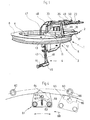
- Fig. 1 eine perspektivische Ansicht einer Lafette mit eingesetzter Waffe und abgenommenem Lukendeckel sowie ohne Abdeckhaube,
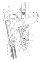
- Fig. 2 einen Längsschnitt mit vertikaler Schnittebene, auf der die Waffenschwenkachse und die Visierschwenkachse senkrecht stehen,
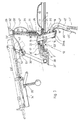
- Fig. 3 einen Schnitt durch eine andere Ausführungsform mit der gleichen Schnittebene wie Fig. 2,
- Fig. 4 die Drehbegrenzung und Rastung des Drehringes,
- Fig. 5 und 6 eine Seiten- bzw. Frontansicht mit aufgesetzter Abdeckhaube und daran aufgebauten Zusatzgeräten in gegenüber den anderen Figuren wesentlich verkleinerter Darstellung und
- Fig. 7 einen Abzug mit umstellbaren Wegbegrenzern.
- 1 is a perspective view of a gun carriage with a weapon inserted and hatch cover removed and without a cover,
- 2 shows a longitudinal section with a vertical sectional plane on which the weapon pivot axis and the sight pivot axis are perpendicular,
- 3 shows a section through another embodiment with the same sectional plane as FIG. 2,
- 4 the rotation limit and locking of the rotating ring,
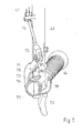
- 5 and 6 are a side or front view with a cover and attachments mounted thereon in a significantly reduced representation compared to the other figures and
- Fig. 7 a deduction with adjustable path limiters.
Die in der Zeichnung dargestellte Lafette umfaßt eine Unterlafette 1 mit darauf aufgebauter Oberlafette 2, eine Visiervorrichtung 3 sowie Betätigungs- und Stellorganen 4, nämlich Höhen- und Seitenrichthebeln. Die Unterlafette 1 umfaßt einen Drehring 5, der in einem am Fahrzeug fest angebrachten Gegenring 6 mittels Kugeln 7 drehbar gelagert ist. Der Ring ist von einer Grundplatte 8 abgedeckt, die nach außen etwas über den Durchmesser des Drehringes 5 vorsteht und deren innerhalb des Drehringes 5 befindlicher Teil einerseits die Oberlafette 2 trägt, die daran befestigt ist, und die andererseits mit einem großen Ausschnitt 9 versehen ist, der durch einen Lukendeckel 10 verschließbar ist, dessen Scharnier sich an der der Oberlafette 2 abgewandten Zone der Grundplatte 8 befindet.The carriage shown in the drawing comprises a
An der Grundplatte 8 ist eine Aufnahme 11 befestigt, die in Art eines Rahmens gestaltet ist. In der Aussparung dieses Rahmens ist eine Walzenblende 12 um eine Visierachse 13 schwenkbar gelagert, die mit der Zylinderachse der Walzenblende 12 zusammenfällt und horizontal, also parallel zur Ebene des Drehringes 5, ausgerichtet ist. In die Walzenblende 12 ist eine Aussparung eingearbeitet, in die die Visiervorrichtung 3 von unten her unter Zwischenfügung einer Abdichtung 14 eingesetzt ist. Die Visiervorrichtung 3 ist als sogenannter Winkelspiegel mit zwei festen Umlenkspiegeln 15 und 16 aufgebaut. Dem oberen Umlenkspiegel 15 ist ein Korn 17 zugeordnet, das an der äußeren, radialen Oberfläche der Walzenblende 12 fest angebracht ist. Dem unteren, inneren Umlenkspiegel 16 ist eine Kimme 18 zugeordnet, die vor einer Einblicköffnung 19 angeordnet ist, die zusammen mit dem unteren Ende der Visiervorrichtung 3 von einer Polsterung 20 umgeben ist. Dabei ist die Kimme 18 an einem Arm 21 angebracht, der seinerseits an der Walzenblende 12 starr befestigt ist. Die Kimme 18 ist bevorzugt in bekannter Weise auf unterschiedliche Entfernungen einstellbar. Die Anordnung von Korn 17, Kimme 18 und Umlenkspiegel 15 und 16 ist so gewählt, daß der äußere Teil einer Visierlinie 22 parallel zu einer Visierlinie einer eingesetzten Waffe 23' ist.On the
Die Aufnahme 11 weist an ihrem rückwärtigen, der Mündung der Waffe 23 abgewandten und dem Ausschnitt 9 zugewandten Bereich eine Rohrhülse 24 auf, in der ein Rohr 25 drehbar gelagert ist, das oben offen ist und an dessen unterer Stirnfläche ein Drehzapfen 26 vorgesehen ist, der in einer Zapfenpfanne 27 der Aufnahme 11 drehbar gelagert ist. Am oberen Ende des Rohres 25 ist ein Arm 28 angebracht, an dessen freiem Ende sich eine zur Visierachse 13 parallele Waffenschwenkachse 29 befindet. Das Rohr 25 ist mittels eines durch einen Hebel 30 lösbaren Schnellverschlusses leicht lösbar an der Rohrhülse 24 befestigt. Zu diesem Zweck ist in das Rohr 25 eine Nut 31 eingearbeitet, in die der Schnellverschluß eingreift. Um die Waffenschwenkachse 29 ist ein Lagergestell 32 schwenkbar, an dem das hintere Ende eines Tragrohres 33 starr befestigt ist. Das Tragrohr 33 ist an seinen beiden Enden derart seitlich gekröpft, daß es die Aufnahme der Waffe 23 nicht hindert. Am vorderen Ende ist an dem Tragrohr 33 eine Halterung 34 befestigt, die Aufnahme- und Befestigungsmittel für die leicht lösbare Fixierung der Waffe 23 trägt.The
Um die gewünschte Zuordnung der Visierlinie 22 zur Waffe 23 trotz der Höhenrichtbarkeit der Waffe aufgrund der Schwenkbewegung um die Waffenschwenkachse 29 zu gewährleisten, ist die Oberlafette 2 als Parallelogramm ausgebildet. Zu diesem Zweck sind an der Walzenblende 12 zwei Arme 36 starr befestigt, die an ihrem äußeren Ende durch einen Querbügel 37 miteinander verbunden und zusätzlich versteift sind. Der Querbügel 37 ist um eine weitere, zur Visierachse 13 und der Waffenschwenkachse 29 parallele Schwenkachse 38 drehbar, die ihrerseits an den Enden der Arme 36 angeordnet und relativ zu den Armen 36 unbeweglich ist. Um die Schwenkachse 38 ist ein Lenker 39 schwenkbar, der vorzugsweise unmittelbar am Querbügel 37 befestigt, beispielsweise angeschweißt ist. Das Ende des Lenkers 39 ist am Tragrohr 33 um eine Achse 40 schwenkbar angelenkt, die relativ zum Tragrohr 33 starr und im übrigen parallel zu den Achsen 13,29 und 38 ist. Das Ende des Lenkers 39 kann leicht lösbar an dem Tragrohr 33 angebracht sein, worauf nach Lösen dieser Verbindung der Lenker um die Schwenkachse 38 nach unten verschwenkbar ist, so daß er etwa parallel zu den Armen 36 liegt. In dieser Stellung wird die Anordnung als Freirichtlafette für die Bekämpfung von Flugzielen im vorwiegend militärischen Einsatz benutzt, wobei die Visiervorrichtuflg 3 nicht benutzt wird. Der Abstand der Achsen 29 und 40 voneinander ist gleich dem Abstand der Achsen 38 und 13 voneinander: Ebenso ist der Abstand der Achsen 38 und 40 voneinander gleich dem Abstand der Achsen 13 und 29 voneinander.In order to ensure the desired assignment of the
Bei der in Fig.3 dargestellten geringfügig veränderten Ausführungsform sind einander entsprechende Teile jeweils mit demselben, durch ein Apostroph ergänztes Bezugszeichen versehen. Bei dieser Ausführungsform ist zur Erleichterung der Benutzung als Freirichtlafette innerhalb des Rohres 25 ein axial unter der Wirkung von Gewichtsausgleichsfedern 41 verschiebbares Rohrstück 42 vorgesehen, das im Abstand von der Waffenschwenkachse 29 an dem Lagergestell 32' angreift und einen Teil des Gewichtes der Waffe 23' aufnimmt, um dem Schützen einen leichteren und damit auch schnelleren Einsatz der Waffe zu ermöglichen.In the slightly modified embodiment shown in FIG. 3, parts which correspond to one another are each provided with the same reference symbol, supplemented by an apostrophe. In this embodiment, to facilitate use as a directional mount within the
Die Betätigungs- und Stellorgane 4 umfassen insbesondere einen Höhenrichthebel 43, der nach Lösen einer Sperre aus der in Fig. 1 dargestellten Betriebslage nach oben wegschwenkbar ist, damit er nicht in den Fahrzeuginnenraum ragt. An dem Höhenrichthebel 43 mit Handgriff 44 ist ein Betätigungshebel 45 angebracht, der bei seinem Heranziehen an dem Handgriff 44 über eine Wirkverbindung in Form eines Gestänges 46 oder eines Bowdenzuges 46' eine Bremse gegen Federdruck löst, wodurch die Walzenblende 12 mit allen an ihr befestigten oder angebrachten Teilen um die Visierachse 13 schwenkbar ist. Die nicht dargestellte Bremse ist federbelastet eingerückt und entgegen der Federwirkung durch den Betätigungshebel 45 und das Gestänge 46 bzw. dem Bowdenzug 46' lösbar. Es versteht sich, daß die Bremse mit der Walzenblende 12 bewegbare Teile einerseits und relativ zur Walzenblende 12 feststehende, an der Grundplatte 8 oder dem Drehring 5 befestigte Teile umfaßt. Bevorzugt ist sie als Backen- oder Lamellenbremse ausgebildet.The actuating and adjusting
An dem Höhenrichthebel 43 ist ferner ein Auslöser angebracht, der über einen Bowdenzug 47 auf den Abzug der Waffe einwirkt. Mittels eines weiteren Bowdenzuges 48 kann beispielsweise die Waffe durchgeladen werden. Der Bowdenzug 48 greift mit einem Betätigungshaken 49 an einem Durchladehebel 50 der Waffe 23 an. (In Fig. ist der Bowdenzug 47 nicht dargestellt.)A trigger is also attached to the leveling
In Fig. ist der Höhenrichthebel 43 mit dem Handgriff 44, jedoch ohne Betätigungshebel 45 dargestellt. In der Nähe des unteren Endes des Höhenrichthebels 43 ist eine zum Handgriff 44 etwa parallele Achse 71 befestigt, um die ein Hebel 72 schwenkbar ist, dessen unteres, über den Handgriff 44. hinaus nach unten vorstehendes Ende als Abzug 73 ausgebildet ist. An dem anderen Ende des zweiarmigen Hebels 72 ist eine Seele 74 des Bowdenzuges 47 mittels einer an ihrem Ende befestigten Gabel 75 angelenkt.In Fig. The leveling
An dem dem zweiarmigen Hebel 72 benachbarten Ende des. Handgriffes 44 ist eine Sicherungswalze 76 um eine Achse 77 in drei Stufen verschwenkbar. Die Achse 77 verläuft etwa parallel zur Längserstreckung des Höhenrichthebels 43 und etwa senkrecht zur Achse 71 sowie radial zur Länge des Handgriffes 44. Am unteren Ende ist an der Sicherungswalze 76 ein Sicherungsflügel 78 befestigt, der zum Verschwenken der Sicherungswalze 76 dient. Am entgegengesetzten oberen Ende der Sicherungswalze 76, wo sich diese im Bereich des oberen Armes des Hebels 72 befindet, an dem die Seele 74 des Bowdenzuges 47 angelenkt ist, ist die Sicherungswalze mit einem Ausschnitt 79 sowie Anfräsungen zur Erzeugung von Anschlagflächen 80 und 81 versehen. Durch Verschwenken der Sicherungswalze 76 mittels des Sicherungsflügels 78 können wahlweise die Anschlagflächen 80, 81 oder der Ausschnitt 79 in die Bewegungsbahn des oberen Armes des zweiarmigen Hebels 72 eingeschwenkt werden. Befindet sich der Sicherungsflügel 78 und damit die Sicherungswalze 76 in der dargestellten Position, dann läßt sich der zweiarmige Hebel 72 nicht in Abzugsrichtung verschwenken, weil der obere Arm an der Anschlagfläche 81 anliegt. Wird der Sicherungsflügel 78 und damit die Sicherungswalze 76 in eine Mittelposition verschwenkt, dann befindet sich die Anschlagfläche 80 in der Bewegungsbahn des oberen Armes des Hebels 72 und läßt eine begrenzte Bewegung zu Wird nun der Abzug 73 betätigt, so wird die Seele 74 vorbewegt und betätigt ihrerseits den Abzug der Waffe 23, wodurch ein Schuß ausgelöst wird. Die betreffende Position des SiçherungsfIügε!s 78 ist am Handgriff 44 mit einem E bezeichnet. Soll ein Feuerstoß ausgelöst werden, muß der Abzug der Waffe 23 weiter durchgezogen werden Um dies zu ermöglichen, muß zuvor der Sicherungsflügel 78 in die mit F bezeichnete dritte Position verschwenkt werden, wodurch der Ausschnitt 79 der Sicherungswalze 76 in die Bewegungsbahn des oberen Armes des Hebels 72 gelangt. Damit läßt sich der Hebel 72 weiter verschwenken und somit auch der Abzug der Waffe 23 so weit durchziehen, bis zur Position Feuerstoß oder Dauerfeuer. Die zugehörige Position des Sicherungsflügels 78 ist in Fig. 7 mit F bezeichnetAt the end of the
Bei der in Fig. 3 dargestellten Ausführungsform führt der Bowdenzug 47' an einem an dem Lenker 39' angebrachten Zwischenhebel 51, der an einem Abzug 52 der Waffe 23' angreift, an deren Abzugsgehäuse er mittels Schnellverschluß befestigt ist.In the embodiment shown in FIG. 3, the Bowden cable 47 'leads to an
Ein weiteres Betätigungsorgan in Gestalt eines Seitenrichthebels ist in der Zeichnung nicht näher dargestellt. Dieser Seitenrichthebel dient zum Verdrehen des Drehringes 5 mit allen daran angebrachten Teilen relativ zum Fahrzeug. An dem Seitenrichthebel ist ebenfalls ein Betätigungsglied zum Lösen einer federbelasteten Bremse vorgesehen, die am Drehring 5 angebracht und mit am Gegenring 6 vorgesehenen Teilen oder Flächen unter Federwirkung in Eingriff kommt. Beispielsweise kann die- innere Zylinderfläche des fahrzeugfesten Gegenringes als Bremsfläche dienen, an der an dem oberen, horizontalen Schenkel des Ringes 5 angebrachte Bremselemente angreifen.Another actuator in the form of a side straightening lever is not shown in the drawing. This side straightening lever is used to turn the
An dem Höhenrichthebel 43 bzw. dem Handgriff 44 ist ferner noch ein ebenfalls in der Zeichnung nicht sichtbarer Auslöser für den Bowdenzug 47 bzw. 47' angebracht, der vorzugsweise mit verstellbaren Anschlägen zur Wegbegrenzung der Abzugsbewegung versehen ist, um den Abzug 52 unterschiedlich weit durchziehen zu können, wodurch es möglich ist, bei Einsatz geeigneter Waffen den Abzugshebel nur so weit auszulösen, daß er die eingestellte Waffenfunktion ausführt, z. B. Sichern, Einzelfeuer, Dauerfeuer oder Feuerstoß.On the leveling
Bei Lafetten, bei denen über den Bowdenzug 48 der Durchladehebel 50 betätigt werden kann, kann das innere, dem Schützen zugewandte Betätigungsende mit einer auslösbaren Sperre versehen sein, die es ermöglicht, den Durchladehebel in der Stellung zu fixieren, in der der Verschluß nach hinten gezogen ist. Dadurch ist eine vollständige Sicherung der Waffe gegen unbeabsichtigtes Auslösen eines Schusses ermöglicht, weil sich auch bei Betätigen des Abzugs kein Schuß lösen kann.In the case of mountings in which the
Bei der in Fig. 3 dargestellten Ausführungsform besteht die Walzenblende 12 aus einem in einem Stück gegossenen Körper 53' aus Panzerstahl, der unter Einhaltung enger Spalte in der Aufnahme 11 schwenkbar gelagert ist. Bei der in den Fig. 1 und 2 dargestellten Ausführungsform dagegen besteht die Walzenblende 12 aus einem Grundkörper 53 und einem diesen Grundkörper an der Mantelfläche und an den Seiten umgebenden Mantel 54 aus gewalztem und gegebenenfalls warmbehandeltem Panzerstahlblech. Dabei besteht der Grundkörper 53 aus einem nicht so widerstandsfähigen Material, beispielsweise aus Leichtmetall und weist einen Spalt 69 zwischen Mantel 54 und Grundkörper 53 auf. Außerdem sind in die Mantelfläche des Grundkörpers 53 mündende Kammern 70 in den Grundkörper 53 eingeformt. Diese Ausbildung hat den Vorteil, daß bei Beschuß sich der Mantel 54 etwas in Richtung zum Grundkörper 53 hin verformen kann, wodurch Aufwerfungen am Rande des Schußkraters die Bewegbarkeit der Walzenblende 12 im Ausschnitt der Aufnahme 11 nicht verhindern. Dadurch ist ein Festklemmen oder eine Begrenzung des Höhenrichtbereiches infolge von Beschußwirkungen weitgehend ausgeschaltet. Um durch den Spalt zwischen Mantel 54 und Aufnahme 11 einfließendes Blei aufzufangen, ist an der Unterseite der Grundplatte 8 eine Lippe 55 bis nahe zum Mantel 54 reichend vorstehend befestigt, die aus einem Stahlblech besteht und die eindringendes Blei, .das sich tangential zum Mantel 54 vom Auftreffort her ausbreitet, abfängt. Das Blei fließt deshalb ein, weil es sich unter der hohen Beanspruchung beim Auftreffen annähernd wie eine Flüssigkeit verhält. Die Waffe 23 bzw. 23' kann, wie in den Fig. 5 und 6 dargestellt, mit einer um die Waffenschwenkachse 29 mitschwenkbaren Abdeckhaube 56 versehen sein, die die Waffe gegen Witterungseinflüsse, Schmutz sowie auch gegen die Einwirkung von Wurfankern und Steinen u. dgl. beim Polizeieinsatz schützt. Die Abdeckhaube 56 deckt auch das Magazin der Waffe ab. Zum Auswechseln des Magazins ist der Lukendeckel 10 an seiner der Abdeckhaube 56 benachbarten Frontseite mit einer Klappe 57 versehen, durch die hindurch ein Magazinwechsel von außen kaum einsehbar durchgeführt werden kann.In the embodiment shown in FIG. 3, the
Auf der Abdeckhaube sind für den Polizeieinsatz Zusatzgeräte, wie beispielsweise Lautsprecher 58 oder auch ein Rundumblinker (blaulicht) 59, aufgebaut. Die Stromversorgung dieser Einheiten sowie einer gegebenenfalls vorgesehenen Funkantenne erfolgt über durch die Abdeckhaube 56 nach innen durchgeführter Kabel. Um hierbei die Drehbewegung der Lafette 1, 2 auf ±180° zuzüglich eines Zusatzschwenkbereiches von etwa 15° bis 30° zu begrenzen, sind an dem Gegenring 6 oder sonstwie fahrzeugfest Anschlagbolzen 60 vorgesehen. An dem Drehring 5 bzw. der Grundplatte 8 ist ein rastbarer Anschlag 61 angebracht, der einen in einer Halterung 62 um einen Zapfen 63 schwenkbaren Riegel 64 umfaßt. Der Riegel 64 hat zwei bogenförmige Anschlagflächen 65 an seinen beiden einander gegenüberliegenden Stirnseiten sowie einen dazwischen befindlichen und radial zur Drehachse des Drehringes 5 nach außen vorstehenden Nocken 66, in dessen Bewegungsbahn beim Verdrehen des Drehringes 5 die Anschlagbolzen 60 ragen, wenn sich der Riegel 64 in seiner in Fig.4 gestrichelt dargestellten mittleren Rastlage befindet. Die Rastung wird bewirkt durch an der dem Nocken 66 gegenüberliegenden Seite des Riegels 64 in diesen eingearbeitete, abgerundete Vertiefungen 67, in die ein federbelasteter Stift 69 eingreift, der in einer Bohrung der Halterung 62 radial zum Zapfen 63 gelagert und geführt ist.Additional devices, such as
Befindet sich der Anschlag 61 außerhalb des Bereiches der Anschlagbolzen 60, so nimmt der Riegel 64 die in Fig. gestrichelt dargestellte mittlere Position ein. Wird nun der Drehring 5 in Richtung eines Pfeiles 68 so weit verschwenkt, daß der Anschlag 61 den ersten Anschlagbolzen 60 passiert, so läuft der Nocken 66 an dem Anschlagbolzen 60 an und verschwenkt den Riegel 64 in die in Fig. 4 ausgezogen dargestellte Position, in der eine der beiden bogenförmigen Anschlagflächen 65 dem in Richtung des Pfeiles 68 nachgeordneten Anschlagbolzen 60 zugewandt ist. Mit dem Anlaufen der Anschlagfläche 65 an den zweiten Anschlagbolzen 60 ist die Drehbewegung endgültig begrenzt. Beim Zurückbewegen läuft der vordere Anschlagbolzen 60 an die dem Nocken 66 benachbarte Fläche an und schwenkt den Riegel 64 in die gestrichelt dargestellte Position zurück. Auf der gegenüberliegenden Seite, also nach einer Drehung von annähernd 360°, erfolgt die Begrenzung in der gleichen Weise, und es sind lediglich die Funktionen der Anschlagbolzen 60 umgewechselt. Es genügen insgesamt zwei Anschlagbolzen 60, wenn eine freie Schwenkbewegung (vor dem Anlaufen an den ersten Anschlagbolzen 60) von etwa zweimal 160" bis 170° gewünscht ist und die Begrenzung nach zweimal 190 bis 200' betragen soll.If the
Die dargestellte Lafette läßt sich als Universallafette sowohl für den Polizeieinsatz als auch für den militärischen Einsatz verwenden und kann sowohl als Scheitellafette als auch als Freirichtlafette benutzt werden. Von Vorteil ist insbesondere auch, daß der Schütze mit der ihm von der Benutzung der Waffe her gewohnten Visierung arbeiten kann, weil eine mechanische Kimme und ein mechanisches Korn verwendet werden können, die in der gleichen Weise gestaltet sind wie die an der Waffe befindliche Visiereinrichtung. Auch kann die Länge der Visierlinie zwischen Kimme und Korn an der Waffe ebenso bemessen sein wie an der Lafette. Das Achsenparallelogramm 13, 29, 38,40 hat als feste Basis die beiden Achsen 13 und 29, um die sich die beiden anderen Achsen entsprechend bewegen, wobei die Waffenachse und die Visierlinie passend zueinander ausgerichtet sind. Durch den Winkelspiegel mit feststehenden Spiegeln erhält man eine preiswerte und robute Visiervorrichtung, die eine gute Gefechtsfeldbeobachtung zuläßt. Alle Betätigungen, wie Zielen, Entsichern, Einzelfeuer, Dauerfeuer und Durchladen, vorzugsweise für das Bekämpfen von Erdzielen, sind bei geschlossenem Lukendeckel 10 unter Panzerungsschutz möglich. Um, vorzugsweise beim militärischen Einsatz, Flugziele wirksam bekämpfen zu können, wird der Lukendeckel 10 geöffnet, und es werden die Schnellverschlüsse an der Achse 40 sowie an Abzug 52 und Durchladehebel 50 gelöst. Damit kann der Schütze ohne jede Einschränkung Flug-und Erdziele bekämpfen. Beim Beschuß von Flugzielen wird bevorzugt ein waffeneigenes Fliegervisier aufgesetzt. Dazu ist die Bremse des Drehringes 5 gelöst und in Lösestellung arretiert. Dabei muß dann die Oberlafette in der Rohrhülse 24 festgestellt werden und nur in der Höhe schwenkbar sein. Besser ist es jedoch, wenn der Drehring gebremst und nicht gelöst bleibt. Es ist dann die Oberlafette an der Rohrhülse 24 um die senkrechte Achse frei schwenkbar und es kann in einer Stellung des Drehringes im Seitenrichtbereich von ca. 150° bequem aus der Luke geschossen werden. Wird ein größerer Seitenrichtbereich benötigt, so wird die Lafette im ' Fahrzeug entsprechend gedreht und dann wieder festgelegt. Bei dieser Betriebsweise ist die Trefferwahrscheinlichkeit gegenüber der zuvor beschriebenen Betriebsweise erhöht.The mount shown can be used as a universal mount for both police and military use and can be used both as a top mount and as an open mount. It is particularly advantageous that the shooter can work with the sight he is used to from using the weapon, because a mechanical rear sight and a mechanical sight can be used, which are designed in the same way as the sighting device on the weapon. The length of the line of sight between the rear sight and the front sight can also be measured on the weapon as well as on the mount. The
Es versteht sich, daß die Erfindung nicht auf die dargestellten Ausführungsbeispiele beschränkt ist, sondern Abweichungen davon möglich sind, ohne den Rahmen der Erfindung zu verlassen. Insbesondere können einzelne der Erfindungsmerkmale für sich oder zu mehreren kombiniert Anwendung finden. Vor allem versteht es sich, daß die Oberlafette 2 unterschiedlich ausgebildete Lagergestelle 32, Tragrohre 33 und Halterungen 34 mit Befestigungsmitteln 35 und Lenker 39 umfassen kann. die auf jeweils unterschiedliche Waffen 23 abgestimmt sind.It goes without saying that the invention is not limited to the exemplary embodiments shown, but deviations are possible without leaving the scope of the invention. In particular, individual features of the invention can be used individually or in combination. Above all, it goes without saying that the
Claims (12)
Applications Claiming Priority (2)
| Application Number | Priority Date | Filing Date | Title |
|---|---|---|---|
| DE2902992 | 1979-01-26 | ||
| DE2902992A DE2902992C3 (en) | 1979-01-26 | 1979-01-26 | Carriage for holding light machine weapons with a deflecting sight |
Publications (2)
| Publication Number | Publication Date |
|---|---|
| EP0013897A1 EP0013897A1 (en) | 1980-08-06 |
| EP0013897B1 true EP0013897B1 (en) | 1982-04-21 |
Family
ID=6061453
Family Applications (1)
| Application Number | Title | Priority Date | Filing Date |
|---|---|---|---|
| EP80100078A Expired EP0013897B1 (en) | 1979-01-26 | 1980-01-08 | Machine-gun mounting |
Country Status (3)
| Country | Link |
|---|---|
| US (1) | US4336743A (en) |
| EP (1) | EP0013897B1 (en) |
| DE (1) | DE2902992C3 (en) |
Families Citing this family (27)
| Publication number | Priority date | Publication date | Assignee | Title |
|---|---|---|---|---|
| JPS61116107A (en) * | 1984-11-09 | 1986-06-03 | Hitachi Ltd | Actuator controller |
| FR2593612B1 (en) * | 1986-01-27 | 1988-05-06 | Sopelem | PERISCOPIC SIGHT DEVICE |
| GB2313178B (en) * | 1988-12-14 | 1998-02-18 | Vickers Shipbuilding & Eng | Improvements in or relating to field howitzers |
| GB8829192D0 (en) * | 1988-12-14 | 1998-03-18 | Vickers Shipbuilding & Eng | Improvements in or relating to field howitzers |
| FR2650385B1 (en) * | 1989-07-31 | 1994-09-09 | Hispano Suiza Sa | LIGHT DEPLOYABLE ANTI-AIR CARE |
| FR2656683B1 (en) * | 1989-12-28 | 1992-03-27 | Hispano Suiza Sa | TURNER FOR LIGHT SHIELD EQUIPPED WITH A LATERAL WEAPON. |
| IL96527A (en) * | 1990-12-03 | 1995-03-30 | Israel Aircraft Ind Ltd | Machine gun apparatus |
| DE4136602A1 (en) * | 1991-11-07 | 1993-05-13 | Wegmann & Co Gmbh | TURNING RINGS FOR A LIGHT WEAPON ON A COMBAT VEHICLE, ESPECIALLY ON A HAT OF A COMBAT ARMOR |
| US6237462B1 (en) * | 1998-05-21 | 2001-05-29 | Tactical Telepresent Technolgies, Inc. | Portable telepresent aiming system |
| US7669513B2 (en) * | 2003-10-09 | 2010-03-02 | Elbit Systems Ltd. | Multiple weapon system for armored vehicle |
| DE102004043711B4 (en) * | 2004-09-09 | 2007-05-31 | Heckler & Koch Gmbh | Freirichtlafette and weapons arrangement with a Freirichtlafette |
| US7743543B2 (en) | 2005-10-06 | 2010-06-29 | Theodore Karagias | Trigger mechanism and a firearm containing the same |
| US7752798B2 (en) * | 2005-10-14 | 2010-07-13 | Mayerle Ronald T | See-through periscope for sighting-in optical or open sights on a firearm |
| US20070251375A1 (en) * | 2006-04-28 | 2007-11-01 | Lockheed Martin Corporation | Segmented gun turret for quick assembly |
| US7802509B2 (en) * | 2007-03-29 | 2010-09-28 | Marcus L Wall | Tactical utility pole system and method of use thereof |
| US20110072956A1 (en) * | 2007-03-29 | 2011-03-31 | Wall Marcus L | Tactical Utility Pole and Door Mount Systems and Methods of Use Thereof |
| US8109192B2 (en) * | 2009-01-28 | 2012-02-07 | Nobles Manufacturing, Inc. | Locking mount system for weapons |
| DE102009007750B3 (en) * | 2009-02-06 | 2010-07-01 | Rheinmetall Landsysteme Gmbh | Safety device of a detachable weapon |
| US20120011963A1 (en) * | 2010-07-19 | 2012-01-19 | Burtek, Inc. | Traverse mechanism |
| FR2979425B1 (en) * | 2011-08-29 | 2013-09-20 | Stdm | DEERTED SHOOTING CONTROL DEVICE FOR THE HANDLING OF A WEAPON IN SITE AND DEPOSITION. |
| US9328996B1 (en) | 2013-01-16 | 2016-05-03 | Raymond A. Lia | Bow sight having extended accuracy range |
| DE102013101635A1 (en) | 2013-02-19 | 2014-08-21 | Krauss-Maffei Wegmann Gmbh & Co. Kg | weapon station |
| US10371479B2 (en) * | 2013-09-11 | 2019-08-06 | Merrill Aviation, Inc. | Stabilized integrated commander's weapon station for combat armored vehicle |
| US9377255B2 (en) | 2014-02-03 | 2016-06-28 | Theodore Karagias | Multi-caliber firearms, bolt mechanisms, bolt lugs, and methods of using the same |
| ITUB20151137A1 (en) * | 2015-05-28 | 2016-11-28 | Oto Melara Spa | FIREARM SUPPORT SYSTEM, PARTICULARLY INTENDED TO BE MOUNTED HANGING FROM A SUPERIOR SURFACE. |
| CA2999996C (en) * | 2015-09-29 | 2019-10-22 | Russell FRANK | Camper shell turret system |
| US11067347B2 (en) | 2018-11-30 | 2021-07-20 | Theodore Karagias | Firearm bolt assembly with a pivoting handle |
Family Cites Families (16)
| Publication number | Priority date | Publication date | Assignee | Title |
|---|---|---|---|---|
| BE501997A (en) * | ||||
| FR742421A (en) * | 1933-03-07 | |||
| GB112058A (en) * | 1917-01-16 | 1917-12-27 | Periscopes And Hyposcopes Ltd | Improvements in Means for Sighting and Manipulating Guns from Cover. |
| FR34678E (en) * | 1926-12-09 | 1929-09-19 | ||
| US2085024A (en) * | 1933-01-05 | 1937-06-29 | Greenhow Maury Jr | Machine gun mount |
| US2383487A (en) * | 1941-03-13 | 1945-08-28 | Melvin M Johnson | Automatic gun |
| US2390516A (en) * | 1941-07-11 | 1945-12-11 | David J Crawford | Gun sight mounting |
| US2441874A (en) * | 1942-02-24 | 1948-05-18 | Harold W Evans | Gun mount for land and water vehicles |
| US2458956A (en) * | 1942-06-26 | 1949-01-11 | Motley Lewis | Gun mounting |
| US2360850A (en) * | 1942-07-01 | 1944-10-24 | Joseph M Colby | Gun mount |
| US2466725A (en) * | 1945-05-22 | 1949-04-12 | Marvin J Minter | Vehicle mounted gun and periscope mounting therefor |
| FR1234832A (en) * | 1959-05-21 | 1960-10-19 | Anciens Etablissements Panhard | Improvements in optical means of pointing guns in turrets |
| DE1196098B (en) * | 1963-12-05 | 1965-07-01 | Walter Ruf Dipl Ing | Holder for light weapons with a telescopic sight |
| CH494940A (en) * | 1966-06-24 | 1970-08-15 | Walter Dipl Ing Ruf | Armored vehicle with a device for holding a light weapon on the roof |
| US3424052A (en) * | 1966-07-21 | 1969-01-28 | Walter Ruf | Mount for light guns |
| US3854377A (en) * | 1972-05-20 | 1974-12-17 | Keller & Knappich Augsburg | Tank turret for automatic weapons |
-
1979
- 1979-01-26 DE DE2902992A patent/DE2902992C3/en not_active Expired
-
1980
- 1980-01-08 EP EP80100078A patent/EP0013897B1/en not_active Expired
- 1980-01-10 US US06/110,909 patent/US4336743A/en not_active Expired - Lifetime
Also Published As
| Publication number | Publication date |
|---|---|
| DE2902992B2 (en) | 1980-11-13 |
| US4336743A (en) | 1982-06-29 |
| DE2902992A1 (en) | 1980-07-31 |
| DE2902992C3 (en) | 1981-09-24 |
| EP0013897A1 (en) | 1980-08-06 |
Similar Documents
| Publication | Publication Date | Title |
|---|---|---|
| EP0013897B1 (en) | Machine-gun mounting | |
| EP1102957B1 (en) | Mounted grenade launcher | |
| DE60210182T2 (en) | Two-armed tower for a military combat vehicle | |
| EP1557634A1 (en) | Device for supporting a weapons platform | |
| EP0152797B1 (en) | Hand gun | |
| EP1557633A1 (en) | Device for mounting and securing a gun station | |
| DE19736948C1 (en) | Swivel mount for a firearm such as a machine gun | |
| EP0378157B1 (en) | Combat vehicle with combat stages and a lifting device | |
| DE3108132C2 (en) | Carriage for armored objects for holding handguns | |
| EP0388762B1 (en) | Weapon module for tanks | |
| EP0844455B1 (en) | Mounting of a gun in an armoured turret | |
| DE946601C (en) | Armored vehicle | |
| DE1081352B (en) | Handgun for shooting from side cover | |
| DE3524244A1 (en) | Armoured track-laying or wheeled combat vehicle | |
| EP0892237A1 (en) | Self-loading gun | |
| DE7813857U1 (en) | ARMORED VEHICLE TOWER PIVOTING AROUND A VERTICAL AXIS | |
| CH494940A (en) | Armored vehicle with a device for holding a light weapon on the roof | |
| AT396991B (en) | RIFLE ARMS, ESPECIALLY GRENADE LAUNCHERS | |
| EP0134775B1 (en) | Mortar | |
| DE19857755C2 (en) | Swiveling visor device | |
| DE660803C (en) | Device for ejecting grenades, which consists of a tube which receives a grenade at the front and has a stop part at the rear with a small handgun detachably attached to it | |
| DE1945141U (en) | HOLDER FOR WEAPONS. | |
| DE2406099A1 (en) | MILITARY FACILITY | |
| DE2064133C3 (en) | Carriage for the installation of light machine weapons | |
| DEE0007959MA (en) |
Legal Events
| Date | Code | Title | Description |
|---|---|---|---|
| PUAI | Public reference made under article 153(3) epc to a published international application that has entered the european phase |
Free format text: ORIGINAL CODE: 0009012 |
|
| AK | Designated contracting states |
Designated state(s): BE CH FR GB IT NL SE |
|
| 17P | Request for examination filed | ||
| ITF | It: translation for a ep patent filed |
Owner name: STUDIO TORTA SOCIETA' SEMPLICE |
|
| GRAA | (expected) grant |
Free format text: ORIGINAL CODE: 0009210 |
|
| AK | Designated contracting states |
Designated state(s): BE CH FR GB IT NL SE |
|
| PGFP | Annual fee paid to national office [announced via postgrant information from national office to epo] |
Ref country code: SE Payment date: 19831231 Year of fee payment: 5 |
|
| PGFP | Annual fee paid to national office [announced via postgrant information from national office to epo] |
Ref country code: FR Payment date: 19840112 Year of fee payment: 5 |
|
| PGFP | Annual fee paid to national office [announced via postgrant information from national office to epo] |
Ref country code: CH Payment date: 19840330 Year of fee payment: 5 |
|
| PGFP | Annual fee paid to national office [announced via postgrant information from national office to epo] |
Ref country code: BE Payment date: 19841231 Year of fee payment: 6 |
|
| REG | Reference to a national code |
Ref country code: FR Ref legal event code: ST |
|
| PGFP | Annual fee paid to national office [announced via postgrant information from national office to epo] |
Ref country code: NL Payment date: 19860131 Year of fee payment: 7 |
|
| REG | Reference to a national code |
Ref country code: FR Ref legal event code: DA |
|
| PG25 | Lapsed in a contracting state [announced via postgrant information from national office to epo] |
Ref country code: SE Effective date: 19870109 |
|
| PG25 | Lapsed in a contracting state [announced via postgrant information from national office to epo] |
Ref country code: CH Effective date: 19870131 |
|
| BERE | Be: lapsed |
Owner name: HECKLER & KOCH G.M.B.H. Effective date: 19870131 |
|
| PG25 | Lapsed in a contracting state [announced via postgrant information from national office to epo] |
Ref country code: NL Effective date: 19870801 |
|
| GBPC | Gb: european patent ceased through non-payment of renewal fee | ||
| NLV4 | Nl: lapsed or anulled due to non-payment of the annual fee | ||
| PG25 | Lapsed in a contracting state [announced via postgrant information from national office to epo] |
Ref country code: FR Free format text: LAPSE BECAUSE OF NON-PAYMENT OF DUE FEES Effective date: 19870930 |
|
| REG | Reference to a national code |
Ref country code: CH Ref legal event code: PL |
|
| REG | Reference to a national code |
Ref country code: FR Ref legal event code: ST |
|
| PG25 | Lapsed in a contracting state [announced via postgrant information from national office to epo] |
Ref country code: GB Effective date: 19881118 |
|
| PG25 | Lapsed in a contracting state [announced via postgrant information from national office to epo] |
Ref country code: BE Effective date: 19890131 |
|
| EUG | Se: european patent has lapsed |
Ref document number: 80100078.7 Effective date: 19870923 |
|
| PLBE | No opposition filed within time limit |
Free format text: ORIGINAL CODE: 0009261 |
|
| STAA | Information on the status of an ep patent application or granted ep patent |
Free format text: STATUS: NO OPPOSITION FILED WITHIN TIME LIMIT |