EP0003603B1 - Verschlussmembran zum Verschliessen einer Dosenöffnung - Google Patents
Verschlussmembran zum Verschliessen einer Dosenöffnung Download PDFInfo
- Publication number
- EP0003603B1 EP0003603B1 EP79100395A EP79100395A EP0003603B1 EP 0003603 B1 EP0003603 B1 EP 0003603B1 EP 79100395 A EP79100395 A EP 79100395A EP 79100395 A EP79100395 A EP 79100395A EP 0003603 B1 EP0003603 B1 EP 0003603B1
- Authority
- EP
- European Patent Office
- Prior art keywords
- membrane
- tab
- opening
- closure
- flat part
- Prior art date
- Legal status (The legal status is an assumption and is not a legal conclusion. Google has not performed a legal analysis and makes no representation as to the accuracy of the status listed.)
- Expired
Links
- 239000012528 membrane Substances 0.000 title claims description 59
- 239000000463 material Substances 0.000 claims description 8
- 239000011888 foil Substances 0.000 claims description 5
- 210000004379 membrane Anatomy 0.000 description 43
- 238000007789 sealing Methods 0.000 description 8
- 230000002093 peripheral effect Effects 0.000 description 4
- XAGFODPZIPBFFR-UHFFFAOYSA-N aluminium Chemical compound [Al] XAGFODPZIPBFFR-UHFFFAOYSA-N 0.000 description 3
- 229910052782 aluminium Inorganic materials 0.000 description 3
- 238000000926 separation method Methods 0.000 description 3
- 238000004026 adhesive bonding Methods 0.000 description 2
- 230000007704 transition Effects 0.000 description 2
- 208000030922 Tibial Meniscus injury Diseases 0.000 description 1
- 238000005452 bending Methods 0.000 description 1
- 239000011248 coating agent Substances 0.000 description 1
- 238000000576 coating method Methods 0.000 description 1
- 238000000034 method Methods 0.000 description 1
- 230000003287 optical effect Effects 0.000 description 1
- 239000002985 plastic film Substances 0.000 description 1
- 229920006255 plastic film Polymers 0.000 description 1
- 238000004080 punching Methods 0.000 description 1
- 239000012173 sealing wax Substances 0.000 description 1
- 230000003313 weakening effect Effects 0.000 description 1
- 238000003466 welding Methods 0.000 description 1
Images
Classifications
-
- B—PERFORMING OPERATIONS; TRANSPORTING
- B65—CONVEYING; PACKING; STORING; HANDLING THIN OR FILAMENTARY MATERIAL
- B65D—CONTAINERS FOR STORAGE OR TRANSPORT OF ARTICLES OR MATERIALS, e.g. BAGS, BARRELS, BOTTLES, BOXES, CANS, CARTONS, CRATES, DRUMS, JARS, TANKS, HOPPERS, FORWARDING CONTAINERS; ACCESSORIES, CLOSURES, OR FITTINGS THEREFOR; PACKAGING ELEMENTS; PACKAGES
- B65D17/00—Rigid or semi-rigid containers specially constructed to be opened by cutting or piercing, or by tearing of frangible members or portions
- B65D17/50—Non-integral frangible members applied to, or inserted in, preformed openings, e.g. tearable strips or plastic plugs
- B65D17/501—Flexible tape or foil-like material
- B65D17/503—Flexible tape or foil-like material applied to the internal part of the container wall only
-
- B—PERFORMING OPERATIONS; TRANSPORTING
- B65—CONVEYING; PACKING; STORING; HANDLING THIN OR FILAMENTARY MATERIAL
- B65D—CONTAINERS FOR STORAGE OR TRANSPORT OF ARTICLES OR MATERIALS, e.g. BAGS, BARRELS, BOTTLES, BOXES, CANS, CARTONS, CRATES, DRUMS, JARS, TANKS, HOPPERS, FORWARDING CONTAINERS; ACCESSORIES, CLOSURES, OR FITTINGS THEREFOR; PACKAGING ELEMENTS; PACKAGES
- B65D2517/00—Containers specially constructed to be opened by cutting, piercing or tearing of wall portions, e.g. preserving cans or tins
- B65D2517/0001—Details
- B65D2517/001—Action for opening container
- B65D2517/0013—Action for opening container pull-out tear panel, e.g. by means of a tear-tab
-
- B—PERFORMING OPERATIONS; TRANSPORTING
- B65—CONVEYING; PACKING; STORING; HANDLING THIN OR FILAMENTARY MATERIAL
- B65D—CONTAINERS FOR STORAGE OR TRANSPORT OF ARTICLES OR MATERIALS, e.g. BAGS, BARRELS, BOTTLES, BOXES, CANS, CARTONS, CRATES, DRUMS, JARS, TANKS, HOPPERS, FORWARDING CONTAINERS; ACCESSORIES, CLOSURES, OR FITTINGS THEREFOR; PACKAGING ELEMENTS; PACKAGES
- B65D2517/00—Containers specially constructed to be opened by cutting, piercing or tearing of wall portions, e.g. preserving cans or tins
- B65D2517/0001—Details
- B65D2517/0058—Other details of container end panel
- B65D2517/0059—General cross-sectional shape of container end panel
- B65D2517/0061—U-shaped
-
- B—PERFORMING OPERATIONS; TRANSPORTING
- B65—CONVEYING; PACKING; STORING; HANDLING THIN OR FILAMENTARY MATERIAL
- B65D—CONTAINERS FOR STORAGE OR TRANSPORT OF ARTICLES OR MATERIALS, e.g. BAGS, BARRELS, BOTTLES, BOXES, CANS, CARTONS, CRATES, DRUMS, JARS, TANKS, HOPPERS, FORWARDING CONTAINERS; ACCESSORIES, CLOSURES, OR FITTINGS THEREFOR; PACKAGING ELEMENTS; PACKAGES
- B65D2517/00—Containers specially constructed to be opened by cutting, piercing or tearing of wall portions, e.g. preserving cans or tins
- B65D2517/50—Non-integral frangible members applied to, or inserted in, a preformed opening
- B65D2517/5002—Details of flexible tape or foil-like material
- B65D2517/5024—Material
- B65D2517/5027—Single layer
-
- B—PERFORMING OPERATIONS; TRANSPORTING
- B65—CONVEYING; PACKING; STORING; HANDLING THIN OR FILAMENTARY MATERIAL
- B65D—CONTAINERS FOR STORAGE OR TRANSPORT OF ARTICLES OR MATERIALS, e.g. BAGS, BARRELS, BOTTLES, BOXES, CANS, CARTONS, CRATES, DRUMS, JARS, TANKS, HOPPERS, FORWARDING CONTAINERS; ACCESSORIES, CLOSURES, OR FITTINGS THEREFOR; PACKAGING ELEMENTS; PACKAGES
- B65D2517/00—Containers specially constructed to be opened by cutting, piercing or tearing of wall portions, e.g. preserving cans or tins
- B65D2517/50—Non-integral frangible members applied to, or inserted in, a preformed opening
- B65D2517/5072—Details of hand grip, tear- or lift-tab
- B65D2517/5083—Details of hand grip, tear- or lift-tab with means facilitating initial lifting of tape, e.g. lift or pull-tabs
Definitions
- the invention relates to a closure membrane for closing a can opening, which membrane has a flat part and peripherally adjoining it an edge zone which is intended to be hermetically sealed to the can, a recess being provided in the flat part of the membrane and this Recess is hermetically sealed by a piece of film attached to the underside of the membrane section.
- a sealing membrane of this type is already known from CH-A-593 180.
- this known closure membrane has the disadvantage that the flap tears in the collar part and the flat membrane part obliquely and irregularly and thereby tears off with a small part of the flat membrane part and part of the collar part, while the majority of the flat membrane part remains in its closed position. This must then be separated from the can wall with a finger or a knife or the like. Angled tearing off occurs especially when the tab is not pulled exactly radially with the finger, but slightly obliquely.
- a closure membrane of the type described at the outset which is characterized in that a bent end of the film piece is inside / the recess and forms the tear-open tab, and that a longitudinal extension of the same underneath the tear-open tab forms the actual film piece closing the cutout and is so firmly connected to the underside of the flat membrane section that when the pull tab is pulled out, the entire flat membrane section is removed from the can opening up to a predetermined separation area, in particular a groove, located at the edge zone of the latter.
- the tear-open tab provided can be produced in a simple manner and with little material expenditure.
- the film part which carries the tear-open tab at one of its free ends is preferably guaranteed to be hermetically sealed in a simple manner by gluing or heat sealing to the underside of the flat part of the closure membrane.
- the actual tear-open tab can be tongue-shaped and, in particular, have the shape of an isosceles triangle with an undulated tip, the continuing part of the tab forming the base of the triangle.
- the transition of the actual tab to its extension is preferably parabolic at the point at which the part is bent.
- the outside of the sealing membrane can be aluminum or silver-colored, while the inside can be colored, e.g. red, which is mostly due to the coating of the film with the sealing wax.
- the film part forming the tear-open tab can be designed in a color so that the e.g. red underside after bending the free end of the tab, in the recess of e.g. silver-colored, flat part of the sealing membrane becomes visible in red and thus stands out clearly.
- the recess in the flat part of the membrane which is preferably produced by punching out, can have the shape of an isosceles triangle with a rounded tip, the base of the triangle preferably extending along the circumferential zone which adjoins the flat part of the membrane.
- the preferably rounded tip of the recess points towards the center of the flat membrane section.
- the size and shape of the cutout may vary depending on the size and shape of the tear tab.
- connection of the closure membrane to the film part, which carries the tear-open tab at its one free end is preferably carried out by gluing or sealing, the actual tab first being bent back onto its extension, and then the edges of the extension projecting on three sides with the recess surrounding edge on the underside of the flat membrane section.
- the remaining side is double-layered due to the bent flap, and consequently, when this side is connected to the edge of the recess in the flat part of the membrane, it is double-bonded or sealed, so that ultimately three layers of the material come together.
- This has the great advantage that, on the one hand, the tab is optimally anchored and is thus protected from tearing off, as occurs in previously known embodiments.
- the three interconnected layers ensure that the sealing membrane has a very high level of strength at the point at which the tensile force acting upwards on the tab acts when the membrane is torn open, and the force is thus transferred directly to the desired separation area.
- the entire area in which the tear force acts can be optimally reinforced with this embodiment of the invention.
- the closure membrane according to the invention has the further advantage that the tear tab is easy to grasp.
- the pull tab is clearly visible, and separate instructions for removing the membrane are completely unnecessary.
- sealing membrane and the tear tab can preferably be made of aluminum or plastic film.
- the blank of a membrane 10 shown in Fig. 1 consists of a circular disc made of a suitable material, e.g. an aluminum foil which is provided with a weakening in the form of a groove 11 arranged concentrically with the center of the pane C.
- the membrane 10 has e.g. a wall thickness of 0.03 mm, while this wall thickness in the groove 11 is only about 0.02 mm.
- the groove 11 surrounds a circular area, which forms the flat part 12 of the membrane 10 after deep drawing.
- the flat part 12 is surrounded peripherally by an upwardly directed collar part 13 which carries at its upper end an annular flange part 14 intended for flanging.
- a recess 15 is provided in the membrane 10 in the area which is intended to form the flat part 12, which has approximately the shape of an isosceles triangle shown with a rounded tip 16 and which tip 16 points towards the center of the pane C.
- the base 17 of the recess 15 advantageously runs along and somewhat distant from the groove 11.
- the transition from the tear-open tab 18 to its longitudinal extension 20 is preferably parabolic on the two sides 21 a, which results in excellent conditions for the welding or also the bonding during application.
- a grip hole 21 can be punched out against the tip 19 of the tear tab 18.
- this grip hole 21 offers optical advantages in connection with the selection of differently colored materials.
- the grip hole 21 makes the other, preferably red, color of the top of the longitudinal extension 20 visible, which enables quick and easy recognition of the tear-open flap 18 and thus an immediate understanding of the entire opening process.
- the edge zone of the membrane 10 forming the upward-facing collar part 13, which adjoins the groove 11 to the outside, is intended for hermetically sealed connection to the can peripheral wall 23 of a can 24, which peripheral wall is inserted into the can 24 via the plane E of the flat section 12 Membrane protrudes upwards.
- the ring flange part 14 is flanged over the can peripheral wall 23 when the membrane 10 is inserted.
- a lid (not shown) is now placed in the depression 26 formed by deep drawing in the closure membrane serving as a guarantee seal.
- FIG. 4 shows how the longitudinal extension 20 of the tear-open tab 18 comes to lie with its edges under the circumferential region 27 of the recess 15 and is connected to it in a hermetically sealed manner. Due to the fact that the tip 19 of the tear-open tab 18 is not completely guided to the edge of the recess 15, the gap 28 widens.
- the tear-open tab 18 Due to the advantageous arrangement of the tear-open tab 18, it can be easily gripped with the fingers and pulled upwards.
- the groove 11 is torn first and when pulling further upwards and outwards on the tab 18, the flat part 12 of the membrane tears easily along the groove 11 from the collar part 13 and can be removed from the can opening 25.
- the tear-off takes place cleanly along the groove 11 without parts of the flat membrane part 12 remaining on the wall, as is easily the case with the known sealing membranes.
Landscapes
- Engineering & Computer Science (AREA)
- Mechanical Engineering (AREA)
- Containers Opened By Tearing Frangible Portions (AREA)
- Closures For Containers (AREA)
Description
- Die Erfindung betrifft eine Verschlussmembran zum Verschliessen einer Dosenöffnung, welche Membran eine flache Partie und peripher daran anschliessend eine Randzone aufweist, die dazu bestimmt ist, hermetisch dicht mit der Dose verbunden zu werden, wobei in der flachen Partie der Membran eine Aussparung vorgesehen ist und diese Aussparung durch ein an der Unterseite der Membranpartie angebrachtes Folienstück hermetisch verschlossen ist.
- Eine Verschlussmembran dieser Art ist bereits aus der CH-A-593 180 bekannt. Jedoch weist diese bekannte Verschlussmembran den Nachteil auf, dass die Lasche den Kragenteil und die flache Membranpartie schräg und unregelmässig einreisst und hierdurch mit einem kleinen Teil der flachen Membranpartie und einem Teil des Kragenteils abreisst, während der grösste Teil der flachen Membranpartie in seiner Verschlusstellung verbleibt. Dieser muss dann mit einem Finger oder einem Messer oder dgl. von der Dosenwandung abgetrennt werden. Ein schräges Abreissen tritt vor allem dann auf, wenn die Lasche mit dem Finger nicht exakt radial, sondern leicht schräg weggezogen wird.
- Diese Nachteile werden vermieden bei einer Verschlussmembran der eingangs beschriebenen Art, welche dadurch gekennzeichnet ist, dass sich ein umgebogenes Ende des Folienstückes innerhalb/der Aussparung befindet und die Aufreisslasche bildet, und dass ein unter der Aufreisslasche liegender Längsfortsatz derselben das eigentliche die Aussparung verschliessende Folienstück bildet und dabei so fest mit der Unterseite der flachen Membranpartie verbunden ist, dass beim Herausziehen der Aufreisslasche die gesamte flache Membranpartie bis zu einem an der Randzone der letzteren gelegenen Solltrennbereich, insbesondere einer Rille, aus der Dosenöffnung herausgenommen wird.
- Der vorgesehene Aufreisslappen lässt sich auf einfache Weise und unter geringem Materialaufwand herstellen. Das Folienteil, das an einem seiner freien Enden die Aufreisslasche trägt, wird vorzugsweise durch Kleben oder Heissiegeln mit der Unterseite der flachen Partie der Verschlussmembran auf einfache Art garantiert hermetisch dichtend verbunden.
- Die eigentliche Aufreisslasche kann zungenförmig sein und dabei besonders die Form eines gleichschenkligen Dreiecks mit aberundeter Spitze besitzen, wobei der sich fortsetzende Teil der Lasche die Basis des Dreiecks bildet. Der Uebergang der eigentlichen Lasche zu ihrem Fortsatz verläuft an der Stelle, an der das Teil umgebogen wird, vorzugsweise parabelförmig.
- In üblicher Weise kann die Aussenseite der Verschlussmembran aluminium- bzw. silberfarbig sein, die Innenseite hingegen farbig, z.B. rot, was meist sowieso durch die Beschichtung der Folie mit dem Siegellack bedingt ist. In gleicher Weise kann das die Aufreisslasche bildende Folienteil farblich ausgebildet sein, und zwar so, dass die z.B. rote Unterseite nach dem Umbiegen des freien Laschenendes, in der Aussparung der z.B. silberfarbigen, flachen Partie der Verschlussmembran rot sichtbar wird und sich dadurch gut erkenntlich abhebt.
- Die Aussparung in der flachen Partie der Membran, die vorzugsweise durch Ausstanzen gefertigt wird, kann die Form eines gleichschenkligen Dreiecks mit abgerundeter Spitze besitzen, wobei die Basis des Dreiecks sich vorzugsweise entlang der Umfangszone, die sich an die flache Partie der Membran anschliesst, erstreckt. Die vorzugsweise abgerundete Spitze der Aussparung zeigt gegen das Zentrum der flachen Membranpartie. Die Grösse und Form der Aussparung kann je nach der gewünschten Grösse und Form der Aufreisslasche veriieren.
- Die Verbindung der Verschlussmembran mit dem Folienteil, das an seinem einen freien Ende die Aufreisslasche trägt, erfolgt vorzugsweise durch Aufkleben oder Aufsiegeln, wobei zuerst die eigentliche Lasche auf ihren Fortsatz zurückgebogen wird, und dann die an drei Seiten vorstehenden Ränder des Fortsatzes mit dem die Aussparung umgebenden Rand auf der Unterseite der flachen Membranpartie verbunden werden.
- Die verbleibende Seite ist durch die umgebogene Lasche doppelschichtig ausgebildet, und folglich erfolgt bei der Verbindung dieser Seite mit dem Rand der Aussparung in der flachen Partie der Membran eine Doppelverklebung oder -versiegelung, sodass letztlich drei Schichten des Materials aufeinander zu liegen kommen. Dies hat den grossen Vorteil, dass einerseits die Lasche optimal verankert wird und so vor einem Abreissen, wie dies bei bereits bekannten Ausführungsformen vorkommt, geschützt ist. Durch die drei miteinander verbundenen Schichten wird erreicht, dass die Verschlussmembran an der Stelle, an der beim Aufreissen der Membran die an der Lasche nach oben wirkende Zugkraft einwirkt, eine sehr grosse Festigkeit hat und die Kraft dadurch direkt auf den Solltrennbereich übergeleitet wird. Der ganze Bereich, in dem die Aufreisskraft angreift, kann mit dieser Ausführungsform der Erfindung in optimaler Weise verstärkt werden.
- Die Verschlussmembran nach der Erfindung hat den weiteren Vorteil, dass die Aufreisslasche leicht ergreifbar ist.
- Durch die Wahl verschiedenfarbiger Materialien tritt die Aufreisslasche deutlich in Erscheinung, und eine separate Anleitung für das Entfernen der Membran ist völlig überflüssig.
- Als Material für die Verschlussmembran und die Aufreisslasche kann vorzugsweise Aluminium- oder Kunststofffolie verwendet werden.
- Im folgenden wird die Erfindung anhand von der in der Zeichnung dargestellten, bevorzugten Ausführungsform im Einzelnen beschrieben.
- In der Zeichnung zeigt:
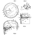
- Fig. 1 einen Rohling der Verschlussmembran in Draufsicht,
- Fig. 2 eine perspektivische Ansicht der Aufreisslasche,
- Fig. 3 einen Querschnitt einer auf dem oberen Ende der Dose angebrachten Verschlussmembran nach Fig. 1 + 2, und
- Fig. 4 eine perspektivische Ansicht der in Fig. 3 gezeigten Anordnung von Dose und Membran nach Entfernen des Dosendeckels.
- Der in Fig. 1 gezeigte Rohling einer Membran 10 besteht aus einer kreisrunden Scheibe aus geeignetem Material, z.B. einer Aluminiumfolie, welche mit einer mit dem Scheibenmittelpunkt C konzentrisch angeordneten Schwächung in Form einer Rille 11 versehen ist. Die Membran 10 weist z.B. eine Wandstärke von 0,03 mm auf, während diese Wandstärke in der Rille 11 nur etwa 0,02 mm beträgt.
- Die Rille 11 umgibt eine Kreisfläche, welche nach dem Tiefziehen die flache Partie 12 der Membran 10 bildet. Nach dem Tiefziehen ist die flache Partie 12 von einem aufwärts, gerichteten Kragenteil 13 peripher umgeben, welches an seinem oberen Ende einen zum Umbördeln bestimmten Ringflanschteil 14 trägt.
- In der Membran 10 ist in demjenigen Bereich, welcher zur Ausbildung der flachen Partie 12 bestimmt ist, eine Aussparung 15 vorgesehen, die näherungsweise die gezeigte Form eines gleichschenkligen Dreiecks mit abgerundeter Spitze 16 aufweist, und welche Spitze 16 gegen den Scheibenmittelpunkt C zeigt. Die Basis 17 der Aussparung 15 verläuft mit Vorteil entlang und etwas distanziert von der Rille 11.
- Die in Fig. 2 gezeigte Aufreisslasche 18, die formlich so ausgebildet sein muss, dass sie bei der Applikation auf die flache Partie 12 der Membran frei in die Aussparung 15 zu liegen kommt, wird mit ihrer vorzugsweise abgerundeten Spitze 19 auf den zusammen mit der Aufreisslasche 18 ein Folienstück 22 bildenden Längsfortsatz 20 der Aufreisslasche 18 zurückgebogen. Der Übergang von der Aufreisslasche 18 zu deren Längsfortsatz 20 erfolgt an den beiden Seiten 21 a vorzugsweise parabelförmig, was bei der Applikation vorzügliche Bedingungen für die Verschweissung oder auch die Verklebung ergibt. Gegen die Spitze 19 der Aufreisslasche 18 kann ein Griffloch 21 ausgestanzt werden. Beim Ergreifen der Lasche 18 wird dadurch einerseits ein Ausgleiten derselben aus den Fingerspitzen vermieden, und anderseits bietet dieses Griffloch 21 im Zusammenhang mit der Wahl verschiedenfarbiger Materialien optische Vorteile. Durch das Griffloch 21 wird nämlich nach Umbiegen der Lasche 18 die andere, vorzugsweise rote Farbe der Oberseite des Längsfortsatzes 20 sichtbar, was ein rasches und leichtes Erkennen der Aufreisslasche 18 und damit ein sofortiges Verstehen des ganzen Oeffnungsvorgangs vermittelt.
- Die den aufwärtsgerichteten Kragenteil 13 bildende Randzone der Membran 10, welcher an die Rille 11 nach aussen anschliesst, ist zum hermetisch dichten Verbinden mit der Dosenumfangswandung 23 einer Dose 24 bestimmt, welche Umfangswandung über die Ebene E der flachen Partie 12 einer in die Dose 24 eingesetzten Membrane nach oben herausragt.
- Der Ringflanschteil 14 ist bei eingesetzter Membrane 10 über die Dosenumfangswandung 23 abgebördelt. In die durch Tiefziehen gebildete Mulde 26 in der als Garantieversiegelung dienenden Verschlussmembran wird nun in üblicher Weise ein Deckel (nicht gezeigt) gesetzt.
- In Fig. 4 wird gezeigt, wie der Längsfortsatz 20 der Aufreisslasche 18 mit seinen Rändern unter den Umfangsbereich 27 der Aussparung 15 zu liegen kommt und mit diesem hermetisch dichtend verbunden wird. Dadurch, dass die Spitze 19 der Aufreisslasche 18 nicht ganz an den Rand der Aussparung 15 geführt wird, verbreitert sich der Spalt 28. Die Aufreisslasche 18, die unter den Teil 29 des Umfangsbereiches 27 zu liegen kommt, bewirkt eine dreifache Materialschicht, was bedingt, dass beim Aufreissen der Membran die an der Lasche 18 nach oben wirkende Zugkraft auf den verstärkten Teil 29 einwirkt, sodass ein Einreissen der Lasche 18 sicher verhindert und ein leichtes Aufbrechen des Solltrennbereiches ermöglicht wird.
- Durch die vorteilhafte Anordnung der Aufreisslasche 18 kann diese leicht mit den Fingern ergriffen und nach oben gezogen werden. Hierbei wird die Rille 11 zuerst eingerissen und beim weiteren Ziehen nach oben und auswärts an der Lasche 18 reisst die flache Partie 12 der Membran mühelos entlang der Rille 11 von dem Kragenteil 13 ab und kann aus der Dosenöffnung 25 herausgenommen werden.
- Der Abriss erfolgt sauber entlang der Rille 11, ohne dass Teile der flachen Membranpartie 12 an der Wandung zurückbleiben, wie dies bei den bekannten Verschlussmembranen leicht der Fall ist.
Claims (10)
Applications Claiming Priority (2)
| Application Number | Priority Date | Filing Date | Title |
|---|---|---|---|
| CH1645/78 | 1978-02-15 | ||
| CH164578A CH623534A5 (de) | 1978-02-15 | 1978-02-15 |
Publications (2)
| Publication Number | Publication Date |
|---|---|
| EP0003603A1 EP0003603A1 (de) | 1979-08-22 |
| EP0003603B1 true EP0003603B1 (de) | 1983-04-27 |
Family
ID=4215299
Family Applications (1)
| Application Number | Title | Priority Date | Filing Date |
|---|---|---|---|
| EP79100395A Expired EP0003603B1 (de) | 1978-02-15 | 1979-02-12 | Verschlussmembran zum Verschliessen einer Dosenöffnung |
Country Status (4)
| Country | Link |
|---|---|
| US (1) | US4195748A (de) |
| EP (1) | EP0003603B1 (de) |
| CH (1) | CH623534A5 (de) |
| DE (1) | DE2965261D1 (de) |
Families Citing this family (3)
| Publication number | Priority date | Publication date | Assignee | Title |
|---|---|---|---|---|
| US4557398A (en) * | 1984-08-17 | 1985-12-10 | International Paper Company | End closure structure for a container |
| US4884751A (en) * | 1988-04-13 | 1989-12-05 | Lil' Duke Sprinkler, Inc. | Lawn sprinkler |
| ES2524478T3 (es) * | 2010-03-18 | 2014-12-09 | Ardagh Mp Group Netherlands B.V. | Cierre para un recipiente abrefácil y un recipiente dotado de tal cierre |
Family Cites Families (6)
| Publication number | Priority date | Publication date | Assignee | Title |
|---|---|---|---|---|
| FR767573A (de) * | 1934-07-19 | |||
| DE1607896A1 (de) * | 1967-09-19 | 1971-10-21 | Nat Can Corp | Bechaelter |
| US3908857A (en) * | 1974-10-15 | 1975-09-30 | Continental Can Co | Tape seal for container |
| US3990603A (en) * | 1975-12-09 | 1976-11-09 | Minnesota Mining And Manufacturing Company | Easy open closure system |
| CH598063A5 (de) * | 1976-05-07 | 1978-04-28 | Sandherr Max Ag | |
| US4108330A (en) * | 1977-06-08 | 1978-08-22 | Minnesota Mining And Manufacturing Company | Easy open container end assembly |
-
1978
- 1978-02-15 CH CH164578A patent/CH623534A5/de not_active IP Right Cessation
-
1979
- 1979-02-12 US US06/011,577 patent/US4195748A/en not_active Expired - Lifetime
- 1979-02-12 EP EP79100395A patent/EP0003603B1/de not_active Expired
- 1979-02-12 DE DE7979100395T patent/DE2965261D1/de not_active Expired
Also Published As
| Publication number | Publication date |
|---|---|
| DE2965261D1 (en) | 1983-06-01 |
| CH623534A5 (de) | 1981-06-15 |
| EP0003603A1 (de) | 1979-08-22 |
| US4195748A (en) | 1980-04-01 |
Similar Documents
| Publication | Publication Date | Title |
|---|---|---|
| EP1768916B1 (de) | Verfahren zum ablösen bzw. abtrennen einer auf den rand des halses einer flasche aufgesiegelten siegelfolie und schraubkappe zur ausführung dieses verfahrens | |
| DE2306810C3 (de) | Dosendeckel aus Metall mit einer eindriickbaren Aufreißlasche | |
| DE60010622T2 (de) | Abdichtende Wiederverschliesskappe für einen zylindrischen Behälter | |
| CH658634A5 (de) | Behaelter mit deckel. | |
| DE1432141A1 (de) | Behaelterdeckel | |
| DE2856647C2 (de) | Aufreißbare Verschlußkapsel, insbesondere Flaschenkapsel | |
| EP0408515A1 (de) | Verpackungsbehälter | |
| DE2308986A1 (de) | Dose mit deckelschutzfalz | |
| DE2209402A1 (de) | Aufreißverschluß mit Verstärkungsrippe | |
| CH677473A5 (en) | Container with resealable cover - has edge with weakened zones forming cone parting surface widening towards top | |
| DE1432081C3 (de) | Behälter | |
| DE3249720C2 (de) | ||
| EP0003603B1 (de) | Verschlussmembran zum Verschliessen einer Dosenöffnung | |
| DE2428395A1 (de) | Leicht zu oeffnender behaelter | |
| DE2253437A1 (de) | Behaelter mit abtrennbarem verschlussdeckel | |
| EP0236736A2 (de) | Aufreissdeckel aus Metall für Dosen | |
| DE3212990A1 (de) | Verfahren zur herstellung einer verschlussmembran fuer behaelter | |
| DE2615812C3 (de) | Dose mit Verschlußmembran | |
| DE2404022C3 (de) | Dosendeckel zum Auffalzen auf einen Dosenkörper | |
| DE2519709A1 (de) | Deckel, insbesondere aus metall, fuer dosen zum verpacken von gasentwickelnden getraenken | |
| EP0601283B1 (de) | Verschluss für eine Medikamentenflasche | |
| DE2823979C2 (de) | Bördelkappe | |
| DE3331741A1 (de) | Verschlusskappe fuer trinkdosen | |
| DE1808907C (de) | Verschluß für eine Behälteröffnung | |
| DE3229081A1 (de) | Deckel fuer einwegbehaelter |
Legal Events
| Date | Code | Title | Description |
|---|---|---|---|
| PUAI | Public reference made under article 153(3) epc to a published international application that has entered the european phase |
Free format text: ORIGINAL CODE: 0009012 |
|
| AK | Designated contracting states |
Designated state(s): BE DE FR GB LU NL SE |
|
| 17P | Request for examination filed | ||
| GRAA | (expected) grant |
Free format text: ORIGINAL CODE: 0009210 |
|
| AK | Designated contracting states |
Designated state(s): BE DE FR GB LU NL SE |
|
| PG25 | Lapsed in a contracting state [announced via postgrant information from national office to epo] |
Ref country code: BE Effective date: 19830427 |
|
| REF | Corresponds to: |
Ref document number: 2965261 Country of ref document: DE Date of ref document: 19830601 |
|
| ET | Fr: translation filed | ||
| PG25 | Lapsed in a contracting state [announced via postgrant information from national office to epo] |
Ref country code: SE Effective date: 19840213 |
|
| PGFP | Annual fee paid to national office [announced via postgrant information from national office to epo] |
Ref country code: FR Payment date: 19840223 Year of fee payment: 6 |
|
| PG25 | Lapsed in a contracting state [announced via postgrant information from national office to epo] |
Ref country code: LU Free format text: LAPSE BECAUSE OF NON-PAYMENT OF DUE FEES Effective date: 19840229 |
|
| PGFP | Annual fee paid to national office [announced via postgrant information from national office to epo] |
Ref country code: NL Payment date: 19840229 Year of fee payment: 6 |
|
| PG25 | Lapsed in a contracting state [announced via postgrant information from national office to epo] |
Ref country code: DE Effective date: 19841101 |
|
| PG25 | Lapsed in a contracting state [announced via postgrant information from national office to epo] |
Ref country code: NL Effective date: 19850901 |
|
| GBPC | Gb: european patent ceased through non-payment of renewal fee | ||
| NLV4 | Nl: lapsed or anulled due to non-payment of the annual fee | ||
| PG25 | Lapsed in a contracting state [announced via postgrant information from national office to epo] |
Ref country code: FR Free format text: LAPSE BECAUSE OF NON-PAYMENT OF DUE FEES Effective date: 19851031 |
|
| REG | Reference to a national code |
Ref country code: FR Ref legal event code: ST |
|
| PG25 | Lapsed in a contracting state [announced via postgrant information from national office to epo] |
Ref country code: GB Effective date: 19881117 |
|
| EUG | Se: european patent has lapsed |
Ref document number: 79100395.7 Effective date: 19850604 |
|
| PLBE | No opposition filed within time limit |
Free format text: ORIGINAL CODE: 0009261 |
|
| STAA | Information on the status of an ep patent application or granted ep patent |
Free format text: STATUS: NO OPPOSITION FILED WITHIN TIME LIMIT |