WO2024157340A1 - リヤサスペンション装置 - Google Patents
リヤサスペンション装置 Download PDFInfo
- Publication number
- WO2024157340A1 WO2024157340A1 PCT/JP2023/002021 JP2023002021W WO2024157340A1 WO 2024157340 A1 WO2024157340 A1 WO 2024157340A1 JP 2023002021 W JP2023002021 W JP 2023002021W WO 2024157340 A1 WO2024157340 A1 WO 2024157340A1
- Authority
- WO
- WIPO (PCT)
- Prior art keywords
- vehicle
- upper link
- link
- suspension device
- rear suspension
- Prior art date
- Legal status (The legal status is an assumption and is not a legal conclusion. Google has not performed a legal analysis and makes no representation as to the accuracy of the status listed.)
- Ceased
Links
Images



Classifications
-
- B—PERFORMING OPERATIONS; TRANSPORTING
- B60—VEHICLES IN GENERAL
- B60G—VEHICLE SUSPENSION ARRANGEMENTS
- B60G3/00—Resilient suspensions for a single wheel
- B60G3/18—Resilient suspensions for a single wheel with two or more pivoted arms, e.g. parallelogram
- B60G3/20—Resilient suspensions for a single wheel with two or more pivoted arms, e.g. parallelogram all arms being rigid
-
- B—PERFORMING OPERATIONS; TRANSPORTING
- B60—VEHICLES IN GENERAL
- B60G—VEHICLE SUSPENSION ARRANGEMENTS
- B60G7/00—Pivoted suspension arms; Accessories thereof
- B60G7/008—Attaching arms to unsprung part of vehicle
-
- B—PERFORMING OPERATIONS; TRANSPORTING
- B60—VEHICLES IN GENERAL
- B60G—VEHICLE SUSPENSION ARRANGEMENTS
- B60G2200/00—Indexing codes relating to suspension types
- B60G2200/10—Independent suspensions
- B60G2200/18—Multilink suspensions, e.g. elastokinematic arrangements
-
- B—PERFORMING OPERATIONS; TRANSPORTING
- B60—VEHICLES IN GENERAL
- B60G—VEHICLE SUSPENSION ARRANGEMENTS
- B60G2200/00—Indexing codes relating to suspension types
- B60G2200/10—Independent suspensions
- B60G2200/18—Multilink suspensions, e.g. elastokinematic arrangements
- B60G2200/184—Assymetric arrangements
-
- B—PERFORMING OPERATIONS; TRANSPORTING
- B60—VEHICLES IN GENERAL
- B60G—VEHICLE SUSPENSION ARRANGEMENTS
- B60G2204/00—Indexing codes related to suspensions per se or to auxiliary parts
- B60G2204/10—Mounting of suspension elements
- B60G2204/12—Mounting of springs or dampers
- B60G2204/124—Mounting of coil springs
- B60G2204/1244—Mounting of coil springs on a suspension arm
-
- B—PERFORMING OPERATIONS; TRANSPORTING
- B60—VEHICLES IN GENERAL
- B60G—VEHICLE SUSPENSION ARRANGEMENTS
- B60G2204/00—Indexing codes related to suspensions per se or to auxiliary parts
- B60G2204/10—Mounting of suspension elements
- B60G2204/12—Mounting of springs or dampers
- B60G2204/129—Damper mount on wheel suspension or knuckle
-
- B—PERFORMING OPERATIONS; TRANSPORTING
- B60—VEHICLES IN GENERAL
- B60G—VEHICLE SUSPENSION ARRANGEMENTS
- B60G2204/00—Indexing codes related to suspensions per se or to auxiliary parts
- B60G2204/10—Mounting of suspension elements
- B60G2204/14—Mounting of suspension arms
- B60G2204/148—Mounting of suspension arms on the unsprung part of the vehicle, e.g. wheel knuckle or rigid axle
-
- B—PERFORMING OPERATIONS; TRANSPORTING
- B60—VEHICLES IN GENERAL
- B60G—VEHICLE SUSPENSION ARRANGEMENTS
- B60G2204/00—Indexing codes related to suspensions per se or to auxiliary parts
- B60G2204/40—Auxiliary suspension parts; Adjustment of suspensions
- B60G2204/41—Elastic mounts, e.g. bushings
Definitions
- the present invention relates to a rear suspension device for an automobile.
- a conventional multi-link rear suspension device that has an A-type upper link and three lower links (Patent Document 1).
- the rear suspension system It is considered desirable for the rear suspension system to have high rigidity in the vehicle width direction to improve cornering responsiveness, while low rigidity in the vehicle's fore-aft direction to reduce shock when going over bumps.
- the A-type upper link of the above-mentioned conventional technology has the problem that it is difficult to set a low rigidity in the vehicle's fore-aft direction.
- the problem that this invention aims to solve is to provide a rear suspension device that can set high rigidity in the vehicle width direction while setting low rigidity in the vehicle front-rear direction.
- the present invention solves the above problem in a rear suspension device that connects the wheels and the vehicle body with two upper links and multiple lower links by making the stiffness of the two upper links different.
- the rigidity of the two upper links is different, so the rigidity in the vehicle width direction can be set high, while the rigidity in the vehicle front-rear direction can be set low.
- FIG. 1 is a perspective view showing a rear suspension device according to a first embodiment of the present invention
- FIG. 2 is a plan view of the rear suspension device of FIG. 1 as viewed from above the vehicle.
- FIG. 2 is a side view of the rear suspension device of FIG. 1 as viewed from the side of the vehicle.
- 2 is a rear view of the rear suspension device of FIG. 1 as seen from the rear of the vehicle.
- 2 is a plan view showing a schematic diagram of an upper link of the rear suspension device of FIG. 1 .
- 2 is a plan view showing a schematic diagram of a lower link of the rear suspension device of FIG. 1 . 1.
- FIG. 4 is a plan view showing a schematic diagram of an upper link according to another example of the rear suspension device of FIG. FIG.
- FIG. 3B is a rear view of FIG. 3A.
- FIG. 6 is a perspective view showing a rear suspension device according to a second embodiment of the present invention.
- 5 is a plan view of the rear suspension device of FIG. 4 as viewed from above the vehicle.
- 5 is a side view of the rear suspension device of FIG. 4 as viewed from the side of the vehicle.
- 5 is a rear view of the rear suspension device of FIG. 4 as seen from the rear of the vehicle.
- FIG. 5 is a plan view illustrating an upper link of the rear suspension device of FIG. 4 .
- FIG. 5 is a plan view showing a schematic diagram of a lower link of the rear suspension device shown in FIG. 4 .
- FIG. 11 is a perspective view showing a rear suspension device according to a third embodiment of the present invention.
- FIG. 8 is a plan view of the rear suspension device of FIG. 7 as viewed from above the vehicle. 8 is a side view of the rear suspension device of FIG. 7 as viewed from the side of the vehicle. 8 is a rear view of the rear suspension device of FIG. 7 as seen from the rear of the vehicle.
- FIG. 8 is a plan view showing a schematic view of an upper link of the rear suspension device of FIG. 7 .
- FIG. 8 is a plan view showing a schematic view of a lower link of the rear suspension device shown in FIG. 7 .
- the rear suspension device according to the present invention is a so-called independent suspension device that can raise and lower the left and right wheels independently, and is also a so-called multi-link suspension device that includes multiple links.
- the present invention will be described using a rear suspension device suspended between the left rear wheel and the vehicle body as an example, but a rear suspension device suspended between the right rear wheel and the vehicle body can also be configured in the same way.
- FIG. 1 is a perspective view showing a rear suspension device 1 according to a first embodiment of the present invention
- Fig. 2A is a plan view of the rear suspension device 1 in Fig. 1 as seen from above the vehicle
- Fig. 2B is a side view of the rear suspension device 1 in Fig. 1 as seen from the side of the vehicle
- Fig. 2C is a rear view of the rear suspension device 1 in Fig. 1 as seen from the rear of the vehicle.
- illustration of tires and wheels is omitted in Fig. 1 and Fig. 2A to Fig. 2C, these tires and wheels are rotatably mounted on knuckles 31, which will be described later, and in the case of a rear-wheel drive vehicle, are connected to a drive shaft (not shown, only the wheel axle 32 is shown).
- the rear suspension device 1 of this embodiment is suspended between the vehicle body 2 and the wheels 3, and includes two upper links and three lower links.
- the two upper links the one on the front side of the vehicle is referred to as the first upper link 11, and the one on the rear side of the vehicle is referred to as the second upper link 12.
- the three lower links the one on the front-to-rear side of the vehicle is referred to as the first lower link 13, the one in the middle of the vehicle in the front-to-rear direction is referred to as the second lower link 14, and the one on the rear-to-rear side of the vehicle in the front-to-rear direction is referred to as the third lower link 15.
- the lower links of the present invention are not limited to only three lower links, and may be configured with two lower links or four or more lower links.
- first upper link 11, the second upper link 12, the first lower link 13, the second lower link 14, and the third lower link 15 are rigid bodies made of processed steel plate, cast products, forged products, or the like. Rubber bushings (detailed illustration omitted) are interposed at both ends of the first upper link 11, the second upper link 12, the first lower link 13, the second lower link 14, and the third lower link 15, with one end swingably attached to a bracket provided on the vehicle body 2, and the other end swingably attached to the knuckle 31 of the wheel 3.
- the vehicle body 2 to which one ends of the first upper link 11, second upper link 12, first lower link 13, second lower link 14, and third lower link 15 are attached can be a rear side member, or a rear suspension member 21 fixed to the rear floor via a rubber bushing 211.
- one ends of the first upper link 11, second upper link 12, first lower link 13, second lower link 14, and third lower link 15 are swingably attached to the rear suspension member 21, but some or all of them may be swingably attached to the rear side member, etc.
- the rear suspension device 1 of this embodiment comprises, in order from the front of the vehicle, a first lower link 13, a second lower link 14, and a third lower link 15.
- the ends of the first lower link 13 and the second lower link 14 on the wheel 3 side are swingably attached to the lower part of the knuckle 31 via rubber bushings
- the ends on the vehicle body 2 side are swingably attached to the lower part of the rear suspension member 21 via rubber bushings.
- the end of the third lower link 15 on the wheel 3 side is swingably attached to the center of the knuckle 31 via a rubber bushing as shown in Figure 2C
- the end on the vehicle body 2 side is swingably attached to the center of the rear suspension member 21 via a rubber bushing.
- the rear suspension device 1 of this embodiment further includes a shock absorber 16 and a spring 17.
- the lower end of the shock absorber 16 of this embodiment is swingably attached to the first lower link 13 as shown in Figures 1 and 2B, and the upper end is attached to the vehicle body 2 (not shown).
- the lower end of the spring 17 of this embodiment is attached to the second lower link 14 as shown in Figures 2A and 2C, and the upper end is attached to the vehicle body 2 (not shown).
- the rear suspension device 1 of this embodiment includes a first upper link 11 and a second upper link 12 as I-type upper links.
- the ends of the first upper link 11 and the second upper link 12 on the wheel 3 side are swingably attached to the top of the knuckle 31 via rubber bushings, and the ends on the vehicle body 2 side are swingably attached to the bottom of the rear suspension member 21 via rubber bushings.
- FIG. 3A is a plan view showing the first upper link 11 and the second upper link 12 of the rear suspension device 1 of this embodiment
- FIG. 3B is a plan view showing the first lower link 13, the second lower link 14, and the third lower link 15 of the rear suspension device 1 of this embodiment.
- the hardness of the rubber bushings for example, is set so that the rigidity of the first upper link 11 and the rigidity of the second upper link 12 are different values.
- the hardness of the rubber bushings is set so that the stiffness of one upper link is higher or lower than that of the other upper link. Increasing the hardness of the rubber bushings increases their stiffness, and the stiffness of the upper link can be increased. Conversely, decreasing the hardness of the rubber bushings decreases their stiffness, and the stiffness of the upper link can be decreased.
- the means for making the stiffness of one upper link different from that of the other upper link is not limited to setting the stiffness of the rubber bushings, but the stiffness of the upper link body may be made different by varying the shape or material of the upper link.
- the stiffness of the upper link refers to the degree to which it is difficult to deform in response to a force input to the upper link; when the deformation in response to the input is small, the stiffness is said to be high, and when the deformation is large, the stiffness is said to be low.
- the rigidity of the upper link having a relatively large inclination angle ⁇ with respect to the vehicle width direction in a plan view of the vehicle is set to be lower than the rigidity of the upper link having a relatively small inclination angle ⁇ with respect to the vehicle width direction.
- the rigidity in the vehicle width direction can be relatively increased, and turning response can be improved.
- the rigidity in the front-rear direction of the vehicle can be relatively decreased, and the impact when going over a step can be reduced.
- FIG. 3C is a plan view showing an upper link according to another example of the rear suspension device 1 of this embodiment.
- the absolute value of the difference between the inclination angle ⁇ 1 of the first upper link 11 and the inclination angle ⁇ 2 of the second upper link 12 is 5° or less and can be said to be equivalent.
- the distance L1 between the wheel axle 32 and the first upper link 11 is compared with the distance L2 between the wheel axle 32 and the second upper link 12, and the rigidity of the upper link with a relatively long distance from the wheel axle 32 is made lower than the rigidity of the upper link with a relatively short distance from the wheel axle.
- the rigidity of the rubber bushing of the second upper link 12 may be reduced and the rigidity of the rubber bushing of the first upper link 11 may be increased so that the rigidity of the second upper link 12 is lower than that of the first upper link 11.
- the distance L between the upper link and the wheel axle 32 may be compared as a distance on the same straight line in the fore-and-aft direction of the vehicle, or as a shortest distance.
- the rigidity in the vehicle width direction can be relatively increased, and turning response can be improved.
- the rigidity in the first upper link 11, which is located at a shorter distance from the wheel axle 32 can be relatively decreased, and the impact when going over a step can be reduced.
- the attachment position P1 of the first upper link 11, which has a relatively high rigidity, on the wheel 3 side in a vehicle side view (or a vehicle front view or a vehicle rear view) is set at a higher position than the attachment position P2 of the second upper link 12, which has a relatively low rigidity, on the wheel 3 side in a vehicle side view (or a vehicle front view or a vehicle rear view).
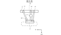
- FIG. 3D is a rear view of FIG. 3A, and is a diagram that shows a schematic diagram for easy understanding of the relationship between the attachment positions P1, P2 of the first upper link 11 and the second upper link 12 on the wheel 3 side.
- the mounting position P1 on the wheel 3 side of the first upper link 11, which has a relatively high rigidity is set at a higher position than the mounting position P2 on the wheel 3 side of the second upper link 12, which has a relatively low rigidity, so that higher lateral rigidity can be ensured compared to the opposite case, i.e., the case where the mounting position P2 on the wheel 3 side of the second upper link 12, which has a relatively low rigidity, is set at a higher position than the mounting position P1 on the wheel 3 side of the first upper link 11, which has a relatively high rigidity.
- a shock absorber 16 installed between the vehicle body 2 and the first lower link 13, a first upper link 11 with relatively high rigidity, the wheel axle 32 (drive shaft in the case of a rear-wheel drive vehicle), a spring 17 installed between the vehicle body 2 and the second lower link 14, and a second upper link 12 with relatively low rigidity.
- the center of rotation of the rear suspension device 1 is set in front of the wheel 3 to suppress changes in posture during braking.
- the stroke of the shock absorber 16 relative to the stroke of the wheel 3 can be made small.
- the height of the upper end of the shock absorber 16 can be set low, and the volume of the luggage compartment behind the cabin can be increased for use in wagons and the like.
- the stroke amount of the spring 17 can be secured.
- the second upper link 12 which has a large inclination angle ⁇ 2 and a relatively low rigidity, can be located rearward of the spring 17, while the first upper link 11, which has a small inclination angle ⁇ 1 and a relatively high rigidity, can be located in front of the wheel axle 32.
- FIG. 4 is a perspective view showing a rear suspension device 1 according to a second embodiment of the present invention
- FIG. 5A is a plan view of the rear suspension device 1 of FIG. 4 as seen from above the vehicle
- FIG. 5B is a side view of the rear suspension device 1 of FIG. 4 as seen from the side of the vehicle
- FIG. 5C is a rear view of the rear suspension device 1 of FIG. 4 as seen from the rear of the vehicle.
- the rear suspension device 1 of this embodiment is suspended between the vehicle body 2 and the wheels 3, and comprises two upper links and three lower links.
- the two upper links the one on the front side of the vehicle is referred to as the first upper link 11, and the one on the rear side of the vehicle is referred to as the second upper link 12.
- the three lower links the one on the front-to-rear side of the vehicle is referred to as the first lower link 13, the one in the middle in the vehicle's fore-to-aft direction is referred to as the second lower link 14, and the one on the rear-to-rear side of the vehicle is referred to as the third lower link 15.
- first lower link 13, second lower link 14, and third lower link 15 the ends of the first lower link 13 and second lower link 14 on the wheel 3 side are swingably attached to the lower part of the knuckle 31 via rubber bushings, and the ends on the vehicle body 2 side are swingably attached to the lower part of the rear suspension member 21 via rubber bushings.
- the end of the third lower link 15 on the wheel 3 side is swingably attached to the center of the knuckle 31 via a rubber bushing, as shown in FIG. 5C, and the end on the vehicle body 2 side is swingably attached to the center of the rear suspension member 21 via a rubber bushing.
- the rear suspension device 1 of this embodiment further includes a shock absorber 16 and a spring 17.
- the rear suspension device 1 of this embodiment differs from the rear suspension device 1 of the first embodiment described above in the mounting position of the shock absorber 16. That is, the lower end of the shock absorber 16 of this embodiment is swingably mounted to the upper part of the knuckle 31 as shown in Figures 4, 5B, and 5C, and the upper end is mounted to the vehicle body 2 (not shown).
- the lower end of the spring 17 of this embodiment is mounted to the second lower link 14 as shown in Figures 5A and 5C, and the upper end is mounted to the vehicle body 2 (not shown).
- the rear suspension device 1 of this embodiment is different from the rear suspension device 1 of the first embodiment described above in the mounting position of the shock absorber 16, but has the same configuration as the rear suspension device 1 of the first embodiment described above, including the configuration of the first upper link 11 and the second upper link 12. Therefore, the same reference numerals as those in Figures 1 to 2C are used in Figures 4 to 5C, and the explanation given in the first embodiment with reference to Figures 1 to 2C is incorporated herein by reference.
- FIG. 6A is a plan view that shows a schematic representation of the first upper link 11 and the second upper link 12 of the rear suspension device 1 of this embodiment
- FIG. 6B is a plan view that shows a schematic representation of the first lower link 13, the second lower link 14, and the third lower link 15 of the rear suspension device 1 of this embodiment.
- a first upper link 11 with a relatively high rigidity As shown in the plan view of Figure 6A, in the rear suspension device 1 of this embodiment, in plan view of the vehicle, from the front in the longitudinal direction of the vehicle, there are arranged a first upper link 11 with a relatively high rigidity, a shock absorber 16 installed between the wheel axle 32 (drive shaft in the case of a rear-wheel drive vehicle) and the vehicle body 2 and the knuckle 31, a spring 17 installed between the vehicle body 2 and the second lower link 14, and a second upper link 12 with a relatively low rigidity.
- the shock absorber 16 As in the rear suspension device 1 of this embodiment, by locating the shock absorber 16 above the wheel axle 32 (or the drive shaft in the case of a rear-wheel drive vehicle), the offset between the shock absorber 16 and the wheel axle 32 is reduced, and it is possible to prevent the cushioning effect of the shock absorber 16 from decreasing due to deflection when the rear suspension device 1 strokes. Furthermore, if the upper end of the shock absorber 16 is set at a high position on the vehicle body 2, the stroke amount of the shock absorber 16 increases. As a result, it is possible to improve ride comfort performance for application to sedans and the like.
- FIG. 7 is an oblique view showing a rear suspension device 1 according to a third embodiment of the present invention
- FIG. 8A is a plan view of the rear suspension device 1 of FIG. 7 as seen from above the vehicle
- FIG. 8B is a side view of the rear suspension device 1 of FIG. 7 as seen from the side of the vehicle
- FIG. 8C is a rear view of the rear suspension device 1 of FIG. 7 as seen from the rear of the vehicle.
- the rear suspension device 1 of this embodiment is suspended between the vehicle body 2 and the wheels 3, and comprises two upper links and three lower links.
- the two upper links the one on the front side of the vehicle is referred to as the first upper link 11, and the one on the rear side of the vehicle is referred to as the second upper link 12.
- the three lower links the one on the front-to-rear side of the vehicle is referred to as the first lower link 13, the one in the middle in the vehicle's fore-to-aft direction is referred to as the second lower link 14, and the one on the rear-to-rear side of the vehicle is referred to as the third lower link 15.
- first lower link 13, second lower link 14, and third lower link 15 the ends of the first lower link 13 and second lower link 14 on the wheel 3 side are swingably attached to the lower part of the knuckle 31 via rubber bushings, and the ends on the vehicle body 2 side are swingably attached to the lower part of the rear suspension member 21 via rubber bushings.
- the end of the third lower link 15 on the wheel 3 side is swingably attached to the center of the knuckle 31 via a rubber bushing, as shown in FIG. 8C, and the end on the vehicle body 2 side is swingably attached to the center of the rear suspension member 21 via a rubber bushing.
- the rear suspension device 1 of this embodiment further includes a shock absorber 16 and a spring 17.
- the rear suspension device 1 of this embodiment differs from the rear suspension device 1 of the first embodiment described above in the mounting position of the shock absorber 16. That is, the lower end of the shock absorber 16 of this embodiment is mounted to the second lower link 14 as shown in Figures 7, 8A and 8C, and the upper end is mounted to the vehicle body 2 (not shown).
- the lower end of the spring 17 of this embodiment is mounted to the second lower link 14 as shown in Figures 8A and 8C, and the upper end is mounted to the vehicle body 2 (not shown).
- the rear suspension device 1 of this embodiment is different from the rear suspension device 1 of the first embodiment described above in the mounting position of the shock absorber 16, but has the same configuration as the rear suspension device 1 of the first embodiment described above, including the configuration of the first upper link 11 and the second upper link 12. Therefore, the same reference numerals as those in Figures 1 to 2C are used in Figures 7 to 8C, and the explanation given in the first embodiment with reference to Figures 1 to 2C is incorporated herein by reference.
- FIG. 9A is a plan view that shows a schematic representation of the first upper link 11 and the second upper link 12 of the rear suspension device 1 of this embodiment
- FIG. 9B is a plan view that shows a schematic representation of the first lower link 13, the second lower link 14, and the third lower link 15 of the rear suspension device 1 of this embodiment.
- a first upper link 11 with a relatively high rigidity As shown in the plan view of Figure 9A, in the rear suspension device 1 of this embodiment, in plan view of the vehicle, from the front in the longitudinal direction of the vehicle, there are arranged a first upper link 11 with a relatively high rigidity, a wheel axle 32 (drive shaft in the case of a rear-wheel drive vehicle), a shock absorber 16 installed between the vehicle body 2 and the second lower link 14, a spring 17 installed between the vehicle body 2 and the second lower link 14, and a second upper link 12 with a relatively low rigidity.
- the spring 17 is supported by the second lower link 14, which is located rearward of the wheel axle 32, so that the stroke amount of the spring 17 can be secured.
- the second upper link 12 which has a large inclination angle ⁇ 2 and a relatively low rigidity, can be located rearward of the spring 17, while the first upper link 11, which has a small inclination angle ⁇ 1 and a relatively high rigidity, can be located in front of the wheel axle 32.
- the stroke of the shock absorber 16 relative to the stroke of the wheel 3 can be increased.
- the ride comfort performance can be improved.
- the height of the upper end of the shock absorber 16 low the volume of the luggage compartment behind the cabin can be increased for application to a station wagon or the like.
- Reference Signs List 1 rear suspension device 11: first upper link 12: second upper link 13: first lower link 14: second lower link 15: third lower link 16: shock absorber 17: spring 2: vehicle body 21: rear suspension member 3: wheel 31: knuckle 32: wheel axle
Landscapes
- Engineering & Computer Science (AREA)
- Mechanical Engineering (AREA)
- Vehicle Body Suspensions (AREA)
Priority Applications (4)
| Application Number | Priority Date | Filing Date | Title |
|---|---|---|---|
| PCT/JP2023/002021 WO2024157340A1 (ja) | 2023-01-24 | 2023-01-24 | リヤサスペンション装置 |
| EP23918059.9A EP4656416A1 (en) | 2023-01-24 | 2023-01-24 | Rear suspension device |
| JP2024572557A JPWO2024157340A1 (https=) | 2023-01-24 | 2023-01-24 | |
| CN202380092077.3A CN120569302A (zh) | 2023-01-24 | 2023-01-24 | 后悬架装置 |
Applications Claiming Priority (1)
| Application Number | Priority Date | Filing Date | Title |
|---|---|---|---|
| PCT/JP2023/002021 WO2024157340A1 (ja) | 2023-01-24 | 2023-01-24 | リヤサスペンション装置 |
Publications (1)
| Publication Number | Publication Date |
|---|---|
| WO2024157340A1 true WO2024157340A1 (ja) | 2024-08-02 |
Family
ID=91970260
Family Applications (1)
| Application Number | Title | Priority Date | Filing Date |
|---|---|---|---|
| PCT/JP2023/002021 Ceased WO2024157340A1 (ja) | 2023-01-24 | 2023-01-24 | リヤサスペンション装置 |
Country Status (4)
| Country | Link |
|---|---|
| EP (1) | EP4656416A1 (https=) |
| JP (1) | JPWO2024157340A1 (https=) |
| CN (1) | CN120569302A (https=) |
| WO (1) | WO2024157340A1 (https=) |
Citations (7)
| Publication number | Priority date | Publication date | Assignee | Title |
|---|---|---|---|---|
| JPH0490910A (ja) * | 1990-08-06 | 1992-03-24 | Honda Motor Co Ltd | 車輪懸架装置 |
| JPH0664427A (ja) * | 1992-08-17 | 1994-03-08 | Nissan Motor Co Ltd | 車両用サスペンション装置 |
| JPH06508080A (ja) * | 1991-03-14 | 1994-09-14 | ドクトル インジエニエール ハー ツエー エフ ポルシエ アクチエンゲゼルシヤフト | サスペンション |
| JP4195208B2 (ja) | 2001-10-03 | 2008-12-10 | 日産自動車株式会社 | リヤサスペンション装置 |
| JP2009090762A (ja) * | 2007-10-05 | 2009-04-30 | Nissan Motor Co Ltd | サスペンション装置 |
| JP2009149296A (ja) * | 2007-12-21 | 2009-07-09 | Dr Ing Hcf Porsche Ag | 自動車のリヤホイールのためのホイールサスペンション |
| JP2015155252A (ja) * | 2014-02-20 | 2015-08-27 | マツダ株式会社 | 自動車のリヤサブフレーム構造 |
-
2023
- 2023-01-24 EP EP23918059.9A patent/EP4656416A1/en not_active Withdrawn
- 2023-01-24 CN CN202380092077.3A patent/CN120569302A/zh active Pending
- 2023-01-24 JP JP2024572557A patent/JPWO2024157340A1/ja active Pending
- 2023-01-24 WO PCT/JP2023/002021 patent/WO2024157340A1/ja not_active Ceased
Patent Citations (7)
| Publication number | Priority date | Publication date | Assignee | Title |
|---|---|---|---|---|
| JPH0490910A (ja) * | 1990-08-06 | 1992-03-24 | Honda Motor Co Ltd | 車輪懸架装置 |
| JPH06508080A (ja) * | 1991-03-14 | 1994-09-14 | ドクトル インジエニエール ハー ツエー エフ ポルシエ アクチエンゲゼルシヤフト | サスペンション |
| JPH0664427A (ja) * | 1992-08-17 | 1994-03-08 | Nissan Motor Co Ltd | 車両用サスペンション装置 |
| JP4195208B2 (ja) | 2001-10-03 | 2008-12-10 | 日産自動車株式会社 | リヤサスペンション装置 |
| JP2009090762A (ja) * | 2007-10-05 | 2009-04-30 | Nissan Motor Co Ltd | サスペンション装置 |
| JP2009149296A (ja) * | 2007-12-21 | 2009-07-09 | Dr Ing Hcf Porsche Ag | 自動車のリヤホイールのためのホイールサスペンション |
| JP2015155252A (ja) * | 2014-02-20 | 2015-08-27 | マツダ株式会社 | 自動車のリヤサブフレーム構造 |
Non-Patent Citations (1)
| Title |
|---|
| See also references of EP4656416A1 |
Also Published As
| Publication number | Publication date |
|---|---|
| CN120569302A (zh) | 2025-08-29 |
| JPWO2024157340A1 (https=) | 2024-08-02 |
| EP4656416A1 (en) | 2025-12-03 |
Similar Documents
| Publication | Publication Date | Title |
|---|---|---|
| US7784806B2 (en) | Independent wheel suspension for the rear wheels of motor vehicles | |
| US5829764A (en) | Semi-trailing arm rear suspension for a vehicle | |
| US20110221157A1 (en) | Vehicle independent suspension | |
| KR20080011411A (ko) | 위시본형 링크 장치 구성요소와 이것을 통합한 서스펜션시스템 | |
| JPH10109510A (ja) | フロントサスペンション装置 | |
| JP2518349B2 (ja) | 車輌用リヤサスペンション | |
| US5765858A (en) | Wheel suspension for rear wheels | |
| EP1888355B1 (en) | Suspension systems | |
| CN100475576C (zh) | 悬架装置 | |
| JP4888189B2 (ja) | サスペンション装置 | |
| US20060091721A1 (en) | Torsion beam suspension system for automobiles and method of manufacturing the same | |
| US3948336A (en) | Vehicle suspension system | |
| WO2024157340A1 (ja) | リヤサスペンション装置 | |
| JP4370518B2 (ja) | 自動車のフロントサスペンション装置 | |
| JPS63134389A (ja) | 四輪バギ−車の前輪懸架装置 | |
| JP2000016042A (ja) | リヤサスペンション構造 | |
| JP2022114514A (ja) | 車両懸架システム | |
| WO2024157339A1 (ja) | リヤサスペンション装置 | |
| JP7558490B2 (ja) | 自動車のサスペンション装置 | |
| KR100451090B1 (ko) | 차량의 리어세미트레일링암 부시 | |
| JPS6248608B2 (https=) | ||
| KR100451091B1 (ko) | 차량의 리어세미트레일링암형 현가장치 | |
| JPH0544162Y2 (https=) | ||
| JP7543967B2 (ja) | 自動車のサスペンション装置 | |
| KR100451089B1 (ko) | 차량의 리어세미트레일링암형 현가장치 |
Legal Events
| Date | Code | Title | Description |
|---|---|---|---|
| 121 | Ep: the epo has been informed by wipo that ep was designated in this application |
Ref document number: 23918059 Country of ref document: EP Kind code of ref document: A1 |
|
| ENP | Entry into the national phase |
Ref document number: 2024572557 Country of ref document: JP Kind code of ref document: A |
|
| WWE | Wipo information: entry into national phase |
Ref document number: 2024572557 Country of ref document: JP |
|
| WWE | Wipo information: entry into national phase |
Ref document number: 202380092077.3 Country of ref document: CN |
|
| NENP | Non-entry into the national phase |
Ref country code: DE |
|
| WWP | Wipo information: published in national office |
Ref document number: 202380092077.3 Country of ref document: CN |
|
| WWP | Wipo information: published in national office |
Ref document number: 2023918059 Country of ref document: EP |