WO2024047760A1 - 基板作業機 - Google Patents
基板作業機 Download PDFInfo
- Publication number
- WO2024047760A1 WO2024047760A1 PCT/JP2022/032629 JP2022032629W WO2024047760A1 WO 2024047760 A1 WO2024047760 A1 WO 2024047760A1 JP 2022032629 W JP2022032629 W JP 2022032629W WO 2024047760 A1 WO2024047760 A1 WO 2024047760A1
- Authority
- WO
- WIPO (PCT)
- Prior art keywords
- cleanliness
- substrate
- board
- monitoring sensor
- component mounting
- Prior art date
- Legal status (The legal status is an assumption and is not a legal conclusion. Google has not performed a legal analysis and makes no representation as to the accuracy of the status listed.)
- Ceased
Links
Images



Classifications
-
- H—ELECTRICITY
- H05—ELECTRIC TECHNIQUES NOT OTHERWISE PROVIDED FOR
- H05K—PRINTED CIRCUITS; CASINGS OR CONSTRUCTIONAL DETAILS OF ELECTRIC APPARATUS; MANUFACTURE OF ASSEMBLAGES OF ELECTRICAL COMPONENTS
- H05K13/00—Apparatus or processes specially adapted for manufacturing or adjusting assemblages of electric components
- H05K13/08—Monitoring manufacture of assemblages
-
- H—ELECTRICITY
- H05—ELECTRIC TECHNIQUES NOT OTHERWISE PROVIDED FOR
- H05K—PRINTED CIRCUITS; CASINGS OR CONSTRUCTIONAL DETAILS OF ELECTRIC APPARATUS; MANUFACTURE OF ASSEMBLAGES OF ELECTRICAL COMPONENTS
- H05K13/00—Apparatus or processes specially adapted for manufacturing or adjusting assemblages of electric components
- H05K13/04—Mounting of components, e.g. of leadless components
- H05K13/0404—Pick-and-place heads or apparatus, e.g. with jaws
Definitions
- the technology disclosed in this specification relates to a board working machine that performs specific work (for example, component mounting work) on a board.
- Countermeasures for conventional PCB working machines include, for example, minimizing gaps in the housing to improve airtightness, and increasing the ability of the air conditioner to supply clean air to increase the internal pressure of the housing and expel dust. Measures are being taken to: However, if such a measure is taken, it becomes necessary to make exclusive settings for the casing in advance according to the cleanliness specifications, which poses a problem of increased costs.
- this specification provides a technique for meeting the user's cleanliness specifications while suppressing high costs.
- a substrate working machine that includes a substrate transport section, a cleanliness monitoring sensor, a movable section, and a control section.
- the substrate transport section transports the substrate to a working position within the apparatus, and transports the board from the working position after the work is completed.
- the cleanliness monitoring sensor detects the cleanliness inside the device.
- the movable part performs a predetermined work on the board at the work position.
- the control section controls the operation of the movable section so as to change the operating speed of the movable section according to the detection result of the cleanliness monitoring sensor. Therefore, according to the above-described configuration, the operating speed of the movable part is appropriately changed depending on the cleanliness level at that time, so that the movable part can perform an appropriate operation at the changed operating speed. Therefore, it is possible to meet the user's cleanliness specifications while suppressing high costs.
- FIG. 1 is a schematic side view showing a component mounting machine of Example 1.
- FIG. 2 is a schematic cross-sectional view taken along line AA of the component mounting machine in FIG. 1.
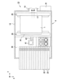
- FIG. 2 is a schematic plan view showing a plurality of component mounting machines according to an embodiment.
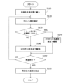
- 3 is a flowchart for explaining the operation of the component mounter according to the first embodiment.
- 7 is another flowchart for explaining the operation of the component mounter of the first embodiment.
- control section may be configured to limit the operating speed of the movable section as the cleanliness level decreases. According to such a configuration, a reduction in cleanliness can be suppressed by limiting the operating speed of the movable part.
- control unit is configured to store a preset reference value regarding cleanliness and to stop the apparatus when the cleanliness decreases and falls below the reference value. You can leave it there. According to such a configuration, it is possible to prevent the device from continuing to operate in a state where the cleanliness level is decreased.
- the board working machine disclosed in this specification is a component mounting machine that mounts components on a board
- the movable part may be an XY robot equipped with a component mounting head. According to such a configuration, the operating speed of the XY robot that performs component mounting work is changed according to the cleanliness level, and the cleanliness inside the apparatus can be maintained at a desired state.
- the cleanliness monitoring sensor may be a particle counter that measures the number and size of dust inside the device. By using a particle counter, the cleanliness inside the device can be quantitatively detected.
- the cleanliness monitoring sensor may perform measurement near the substrate that has been transported to the work position by the substrate transport section. According to such a configuration, by arranging the cleanliness monitoring sensor near the substrate, it is possible to appropriately monitor the cleanliness of the space where work is performed on the substrate.
- the board working machine disclosed in this specification may further include a parts camera that images the parts near the board transport section.
- the cleanliness monitoring sensor may be disposed between the substrate transport section and the parts camera.
- FIG. 1 is a schematic side view showing a component mounting machine 21 of this embodiment.
- FIG. 2 is a schematic cross-sectional view taken along line AA in FIG.
- FIG. 3 is a schematic plan view showing a plurality of component mounting machines 21 of this embodiment.
- the component mounter 21 is a device for mounting components 2 on the board 1, and is a device that mounts the components 2 on the board 1 along the longitudinal direction (X direction) of the board transport path 4 that transports the board 1.
- a plurality of component mounting machines 21 are installed together with other board working machines in a component production line.
- a printing machine (not shown) is provided upstream of the plurality of component mounting machines 21 .
- the printing machine prints a solder pattern on the board 1, and carries out the printed board 1 to a plurality of component mounting machines 21.
- a board inspection machine and a reflow machine are arranged downstream of the plurality of component mounting machines 21.
- the board inspection machine inspects the board 1 after component mounting carried out from the plurality of component mounting machines 21.
- the board inspection machine is, for example, a board appearance inspection machine, and inspects whether the component 2 is normally mounted on the board 1 or not. If the component 2 is normally mounted on the board 1, the board inspection machine carries out the board 1 to a reflow machine.
- the reflow machine performs a reflow process on the board 1 inspected by the board inspection machine. That is, the reflow machine heats the board 1 that has been brought in to melt the solder and solder the component 2 to the board 1.
- the various board working machines described above, including the component mounting machine 21 are installed, for example, in a clean room.
- the component mounting machine 21 includes a plurality of component feeders 22, a head unit 23, an XY robot 24 for moving the head unit 23, a board transfer lane 25, an operation panel 26, an air conditioner (16, 17, 14), a parts camera 41, and a control unit. It is equipped with a device 31 and the like.
- Each component feeder 22 accommodates a plurality of components 2.
- the component feeder 22 is detachably attached to the feeder holding section 30 and supplies the component 2 to the holder 23a of the head unit 23.
- the specific configuration of the component feeder 22 is not limited. For example, a tape type feeder that stores multiple parts 2 on a tape, a tray type feeder that stores multiple parts 2 on a tray, or a bulk type feeder that stores multiple parts 2 randomly in a container. There may be.
- the XY robot 24 which is a movable part, moves the head unit 23 between above the component feeder 22 and above the substrate 1 by moving the moving base 24a in the X direction and the Y direction.
- the XY robot 24 includes a guide rail that guides the moving base 24a, a moving mechanism that moves the moving base 24a along the guide rail, a motor that drives the moving mechanism, and the like.
- the XY robot 24 is housed inside the housing 12 and is placed above the substrate 1.
- a head unit 23 is attached to the moving base 24a. The head unit 23 is moved in the space from above the component feeder 22 to above the substrate 1 by the XY robot 24.
- the head unit 23 is a movable unit that attaches the component 2 to the board 1.
- the head unit 23 includes a holder 23a and a component mounting head 23b. Holder 23a is attached to moving base 24a.
- the component mounting head 23b is detachably supported by the holder 23a.
- the component mounting head 23b includes a plurality of suction nozzles 29.
- the plurality of suction nozzles 29 are detachably supported by the component mounting head 23b.
- the plurality of suction nozzles 29 are configured to be able to suction the component 2 while being raised and lowered in the vertical direction (Z direction in the drawing) by an actuator (not shown) housed in the component mounting head 23b.
- the suction nozzle 29 is moved downward until the suction surface of the suction nozzle 29 comes into contact with the component 2 housed in the component feeder 22.
- the suction nozzle 29 suctions the component 2, and the suction nozzle 29 is moved upward.
- the XY robot 24 is driven to position the component mounting head 23b with respect to the substrate 1.
- the component 2 is mounted on the substrate 1. Note that the component mounting head 23b and the suction nozzle 29 are automatically replaced by a replacement robot (not shown).
- the board transport lane 25 which is a board transport unit, performs operations such as transporting the board 1 to the work position P1 (i.e., component mounting position) in the device, positioning the board 1 before mounting components at the work position P1, This is a device that performs an operation of carrying out the board 1 after mounting components from the work position P1 to the outside of the device.
- the substrate transport lane 25 can also be regarded as a movable part that performs a predetermined operation on the substrate 1 at the operation position P1.
- the substrate conveyance lane 25 of this embodiment may be configured by, for example, a pair of belt conveyors, a support device (not shown) that is attached to the belt conveyor and supports the substrate 1 from below, and a drive device that drives the belt conveyor. Can be done.
- the substrate 1 is transported from upstream (left side in FIG. 3) to downstream (right side in FIG. 3).
- the air conditioner is a device for supplying clean air into the device, and includes an intake fan 16, an exhaust fan 17, and a filter 14.
- the intake fan 16 is installed in the upper region within the housing 12 .
- the filter 14 is attached to the ceiling of the housing 12.
- the intake fan 16 is a device for drawing air from outside the casing 12 into the inside of the casing 12. Air passes through the filter 14 when it is drawn into the housing 12 by the action of the intake fan 16 .
- the air that has passed through the filter 14 flows downward and reaches the working position P1 where the substrate 1 is placed (see arrow A1 in FIG. 1).
- the filter 14 collects dust contained in the air outside the housing 12 and purifies the air.
- the filter 14 is not particularly limited, for example, a HEPA filter (High Efficiency Particulate Air Filter) can be used.
- the exhaust fan 17 is installed in the rear area within the housing 12.
- An exhaust duct 13 is provided in the housing 12 near the installation position of the exhaust fan 17.
- the exhaust fan 17 is a device for exhausting air inside the housing 12 to the outside of the housing 12 via the exhaust duct 13.
- the air that has reached the working position P1 flows sideways and is discharged from the exhaust duct 13 (see arrow A2 in FIG. 1).
- the parts camera 41 is provided between the board transport lane 25 and the parts feeder 22 at a position below the moving path of the component mounting head 23b.
- the parts camera 41 is a component imaging camera for capturing an image of the component 2 sucked by the component mounting head 23b from below.
- a digital imaging device having an imaging element such as a CCD (Charge Coupled Device) or a CMOS (Complementary Metal Oxide Semiconductor) is used.
- the control device 31 (control unit) is configured using a computer including a CPU, ROM, and RAM.
- the control device 31 is communicably connected to the component feeder 22, component mounting head 23b, XY robot 24, board transfer lane 25, operation panel 26, parts camera 41, and exchange robot via a bus.
- a production management computer 6 that stores production programs is connected to the control device 31 so as to be able to communicate with each other via a bus (see FIG. 3).
- Each control device 31 controls the operation of each part (component feeder 22, component mounting head 23b, XY robot 24, substrate transfer lane 25, operation panel 26, exchange robot) based on a production program. Through this control, each control device 31 executes a mounting process for mounting a plurality of components 2 on the board 1, and the like.
- the component mounting machine 21 further includes a cleanliness monitoring sensor 42 for detecting the cleanliness of the air inside the device.
- the cleanliness monitoring sensor 42 of this embodiment is a particle counter.
- a particle counter measures the number and size of dust in the air by irradiating the sucked air with a laser and receiving scattered light from the particles.
- the cleanliness monitoring sensor 42 performs measurement near the substrate 1 being transported to the work position P1 by the substrate transport lane 25. More specifically, the cleanliness monitoring sensor 42 is disposed between the substrate conveyance lane 25 and a parts camera 41 for photographing parts disposed in the vicinity thereof.
- the height of the air intake portion of the cleanliness monitoring sensor 42 is set at a position approximately equal to the height of the substrate 1.
- the cleanliness monitoring sensor 42 is communicably connected to the control device 31 and always outputs a sensor output signal to the control device 31. Therefore, the control device 31 can constantly monitor the cleanliness inside the device. Further, as shown in FIG. 3, in this embodiment, the cleanliness monitoring sensor 42 is provided in each of the plurality of component mounting machines 21.
- the control device 31 of each component mounting machine 21 stores a moving part operation speed control program, which will be described later, in a storage area. The moving part operation speed control program is executed independently for each component mounting machine 21.
- the control unit controls the operation of the movable part so as to change the operating speed of the movable part according to the detection result of the cleanliness monitoring sensor 42. That is, the control device 31 of this embodiment controls the operation of the XY robot 24 so as to change the operation speed of the XY robot 24 according to the detection result of the cleanliness monitoring sensor 42. Specifically, the control device 31 limits the operating speed of the XY robot 24 as the cleanliness level decreases. Note that the operating speed of the XY robot 24 can be set for each component type. For example, the storage area of the control device 31 stores a production program that sets the operating speed (that is, normal operating speed, limited operating speed) of the XY robot 24 for each component type.
- the control device 31 determines the operating speed for each part type based on the production program and the cleanliness detection results. Further, the control device 31 stores in a storage area a first reference value C1 that is set in advance regarding the degree of cleanliness. The control device 31 is configured to determine whether to limit the operating speed of the XY robot 24 based on the first reference value C1. Note that the value of the first reference value C1 is appropriately set based on the specifications of the degree of cleanliness desired by the user.
- the control device 31 executes the following steps according to the moving part operation speed control program. First, the control device 31 drives the substrate transport lane 25, carries the substrate 1 outside the device to the work position P1 inside the device, and positions it (step S110). Next, the control device 31 inputs the sensor output signal of the cleanliness monitoring sensor 42 in order to obtain a measured value of the cleanliness level (step S120). Next, the control device 31 reads the first reference value C1 from the storage area and compares the input cleanliness measurement value with the first reference value C1 (step S130).
- step S130 If the control device 31 determines that the measured value of the cleanliness is equal to or higher than the first reference value C1, that is, if it determines that the cleanliness in the device satisfies the user's specifications (YES in step S130), The control device 31 moves to step S170.
- step S170 the control device 31 controls the XY robot 24 to operate at a normal speed without particularly limiting the operating speed of the XY robot 24, and proceeds to the next step S150.
- step (NO in S130) the control device 31 moves to step S140.
- step S140 the control device 31 limits the operating speed of the XY robot 24, controls the XY robot 24 to operate at a low speed, and proceeds to the next step S150.
- step S150 the control device 31 determines whether the component mounting work has been completed.
- control device 31 determines that the component mounting work has not yet been completed (NO in step S150)
- the control device 31 returns to step S120, measures the cleanliness, and compares the measured value of the cleanliness with the first reference value C1. The comparison and judgment of , and driving the XY robot 24 at normal speed or low speed are repeated.
- the control device 31 determines that the component mounting work has been completed (YES in step S150)
- the control device 31 moves to step S160 and carries out the board 1 after the component mounting is carried out of the device.
- the component mounter 21 may operate in a procedure different from the flowchart in FIG. 4. Next, the operation of the component mounter 21 will be explained based on another flowchart shown in FIG.
- two types of reference values (a first reference value C1 and a second reference value C2) are set in advance regarding the degree of cleanliness.
- the second reference value C2 is a reference value set corresponding to a lower cleanliness level than the first reference value C1.
- the control device 31 first carries the substrate 1 to the work position P1 and positions it, then inputs the sensor output signal of the cleanliness monitoring sensor 42, and further compares the measured value of the cleanliness with the first reference value C1 ( Steps S110 to S130). When the control device 31 determines that the measured value of the degree of cleanliness is equal to or greater than the first reference value C1 (YES in step S130), the control device 31 moves to step S170. In step S170, the control device 31 controls the XY robot 24 to operate at a normal speed without particularly limiting the operating speed of the XY robot 24, and proceeds to the next step S150.
- step S135 the control device 31 reads the second reference value C2 from the storage area, and compares the input cleanliness measurement value with the second reference value C2. If the control device 31 determines that the measured value of the cleanliness is equal to or higher than the second reference value C2, that is, the cleanliness inside the device satisfies the user's specifications, but a relatively small decrease in the cleanliness has occurred. If it is determined that there is one (YES in step S135), the control device 31 moves to step S140.
- step S140 the control device 31 limits the operating speed of the XY robot 24, controls the XY robot 24 to operate at a low speed, and proceeds to the next step S150. However, if the control device 31 determines that the measured value of the cleanliness is not equal to or higher than the second reference value C2, that is, the cleanliness inside the device does not meet the user's specifications, and a relatively large decrease in the cleanliness occurs. If it is determined that it is (NO in step S135), the control device 31 moves to step S180. In step S180, the control device 31 stops the XY robot 24 without operating it, and returns to step S120. Note that even if it is determined that the component mounting work is not completed after proceeding to step S150 (NO in step S150), the process similarly returns to step S120.
- step S150 determines that the component mounting work has been completed (YES in step S150)
- step S160 carries out the board 1 after the component mounting is carried out of the device.
- the control device 31 maintains the operation of the air conditioner to clean the air. Control what happens.
- the measured value of cleanliness recovers to the second reference value C2 or higher
- the XY robot 24 starts operating at low speed
- the XY robot 24 starts operating at normal speed. Start.
- the control device 31 controls the operation of the movable part so as to change the operating speed of the movable part according to the detection result of the cleanliness monitoring sensor 42. . That is, the control device 31 controls the operation of the XY robot 24 so as to change the operation speed of the XY robot 24 according to the detection result of the cleanliness monitoring sensor 42.
- the control device 31 of this embodiment can suppress the decrease in the cleanliness level by limiting the operating speed of the XY robot 24 as the cleanliness level decreases.
- the component mounting work can be continued while suppressing the occurrence of airflow turbulence so as not to reduce the cleanliness.
- component mounting work can be continued in an environment that satisfies the user's cleanliness specifications, and highly reliable and high quality boards 1 can be manufactured while maintaining productivity to some extent.
- the control device 31 stores preset reference values regarding cleanliness (first reference value C1 and second reference value C2), and also stores the reference values set in advance regarding cleanliness. 2. If the value falls below the reference value C2, the device is stopped. If component mounting work is continued in a state where the cleanliness level is greatly reduced, not only will the reliability and quality of the manufactured board 1 deteriorate, but also the turbulence of airflow within the device will not be resolved. In contrast, in this embodiment, the component mounting work is not performed until the cleanliness is restored to a state that satisfies the user's cleanliness specifications, and the component mounting work is restarted after the cleanliness is restored. Therefore, the reliability and quality of the manufactured substrate 1 can be maintained at high levels.
- a particle counter is used as the cleanliness monitoring sensor 42 to measure the number and size of dust inside the device. Since the particle counter is a relatively small device, it can be easily installed at a desired location within the housing 12. Furthermore, the degree of cleanliness can be accurately measured by measuring the number and size of particles in the air.
- the cleanliness monitoring sensor 42 performs measurement near the board 1 being transported to the work position P1 by the board transport lane 25. More specifically, the cleanliness monitoring sensor 42 is disposed between the substrate transport lane 25 and a parts camera 41 for photographing parts arranged near the board transport lane 25, and performs measurement there. Therefore, the cleanliness of the air in the area where component mounting operations are performed can be measured more accurately.
- Example 1 has been described above, the specific aspects are not limited to Example 1 above.
- the board working machine is the component mounting machine 21 that mounts the component 2 on the board 1
- the movable part that is subject to operation speed control according to the cleanliness level is the XY robot 24. It is not limited to the configuration.
- something other than the XY robot 24 for example, an exchange robot, a substrate transfer lane 25, etc. may be added as a movable part subject to operation speed control.
- the component mounting machine 21 was the board working machine subject to the operation speed control according to the cleanliness level, but the structure is not limited to this.
- a board working machine other than the component mounting machine 21 for example, a printing machine, a visual inspection machine, etc.
- the substrate working machine is a printing machine
- the operating speed of its movable part XY robot that drives the print head and squeegee
- the substrate working machine is an appearance inspection machine
- the operating speed of the movable part XY robot that drives the camera
- a particle counter is used as the cleanliness monitoring sensor 42 that detects the cleanliness inside the apparatus, but the configuration is not limited to this.
- a cleanliness monitoring sensor other than a particle counter may be used.
- the cleanliness monitoring sensor 42 was disposed between the substrate transport lane 25 and the parts camera 41, but the configuration is not limited to this.
- the cleanliness monitoring sensor 42 may be provided at a different location than between the substrate transport lane 25 and the parts camera 41.
- one cleanliness monitoring sensor 42 is provided for each component mounting machine 21, a plurality of cleanliness monitoring sensors 42 may be provided.
- the cleanliness monitoring sensor 42 may be provided in some, but not all, of the plurality of component mounting machines 21.
- the cleanliness monitoring sensor 42 may be provided in only one component mounter 21 (for example, only in the first component mounter 21).
- the operating speed of the movable parts of all component mounting machines 21 may be uniformly controlled based on the measurement results of the cleanliness monitoring sensor 42.
- a cleanliness monitoring sensor 42 may be provided for every other component mounting machine 21 of the plurality of component mounting machines 21. In this case, the operating speeds of the movable parts of two adjacent component mounting machines 21 may be uniformly controlled based on the measurement results of the cleanliness monitoring sensor 42.
- Board 2 Component 21: Component mounting machine 23 as a board working machine: Component mounting head 24: XY robot 25 as a movable part: Board transport lane 31 as a board transport section: Control device 41 as a control section: Parts Camera 42: Cleanliness monitoring sensor
Landscapes
- Engineering & Computer Science (AREA)
- Manufacturing & Machinery (AREA)
- Microelectronics & Electronic Packaging (AREA)
- Operations Research (AREA)
- Supply And Installment Of Electrical Components (AREA)
Abstract
Description
2: 部品
21: 基板作業機としての部品実装機
23: 部品実装ヘッド
24: 可動部としてのXYロボット
25: 基板搬送部としての基板搬送レーン
31: 制御部としての制御装置
41: パーツカメラ
42: クリーン度監視センサ
C1: 第1基準値
C2: 第2基準値
P1: 作業位置
Claims (7)
- 基板を装置内の作業位置まで搬入し、作業の完了後に前記基板を前記作業位置から搬出する基板搬送部と、
装置内のクリーン度を検知するクリーン度監視センサと、
前記作業位置にある前記基板に対して所定の作業を行う可動部と、
前記クリーン度監視センサの検知結果に応じて前記可動部の動作速度を変更するように前記可動部の動作を制御する制御部と、を備える基板作業機。 - 前記制御部は、前記クリーン度の低下に伴って前記可動部の動作速度に制限を加えるように構成されている、請求項1に記載の基板作業機。
- 前記制御部は、前記クリーン度に関してあらかじめ設定された基準値を記憶すると共に、前記クリーン度が低下して前記基準値を下回った場合に装置を停止させるように構成されている、請求項2に記載の基板作業機。
- 前記基板作業機は、前記基板に部品を実装する部品実装機であり、前記可動部は、部品実装ヘッドを備えたXYロボットである、請求項1~3のいずれか1項に記載の基板作業機。
- 前記クリーン度監視センサは、装置内の塵埃の数及び大きさを計測するパーティクルカウンタである、請求項1~3のいずれか1項に記載の基板作業機。
- 前記クリーン度監視センサは、前記基板搬送部によって前記作業位置に搬送されてきた前記基板の近傍にて計測を行う、請求項5に記載の基板作業機。
- 前記基板搬送部の近傍に前記部品を撮像するパーツカメラがさらに配設され、
前記クリーン度監視センサは、前記基板搬送部と前記パーツカメラとの間に配設されている、請求項6に記載の基板作業機。
Priority Applications (3)
| Application Number | Priority Date | Filing Date | Title |
|---|---|---|---|
| JP2024543662A JPWO2024047760A1 (ja) | 2022-08-30 | 2022-08-30 | |
| PCT/JP2022/032629 WO2024047760A1 (ja) | 2022-08-30 | 2022-08-30 | 基板作業機 |
| DE112022007717.4T DE112022007717T5 (de) | 2022-08-30 | 2022-08-30 | Platinenbearbeitungsmaschine |
Applications Claiming Priority (1)
| Application Number | Priority Date | Filing Date | Title |
|---|---|---|---|
| PCT/JP2022/032629 WO2024047760A1 (ja) | 2022-08-30 | 2022-08-30 | 基板作業機 |
Publications (1)
| Publication Number | Publication Date |
|---|---|
| WO2024047760A1 true WO2024047760A1 (ja) | 2024-03-07 |
Family
ID=90099203
Family Applications (1)
| Application Number | Title | Priority Date | Filing Date |
|---|---|---|---|
| PCT/JP2022/032629 Ceased WO2024047760A1 (ja) | 2022-08-30 | 2022-08-30 | 基板作業機 |
Country Status (3)
| Country | Link |
|---|---|
| JP (1) | JPWO2024047760A1 (ja) |
| DE (1) | DE112022007717T5 (ja) |
| WO (1) | WO2024047760A1 (ja) |
Cited By (1)
| Publication number | Priority date | Publication date | Assignee | Title |
|---|---|---|---|---|
| WO2025191764A1 (ja) * | 2024-03-14 | 2025-09-18 | 株式会社Fuji | 基板生産装置及びファン制御装置 |
Citations (3)
| Publication number | Priority date | Publication date | Assignee | Title |
|---|---|---|---|---|
| JP2005277212A (ja) * | 2004-03-25 | 2005-10-06 | Sony Corp | 部品実装装置 |
| JP2008147705A (ja) * | 2008-02-25 | 2008-06-26 | Matsushita Electric Ind Co Ltd | 電子部品実装装置 |
| JP2018064052A (ja) * | 2016-10-14 | 2018-04-19 | 富士機械製造株式会社 | 部品実装ライン |
-
2022
- 2022-08-30 JP JP2024543662A patent/JPWO2024047760A1/ja active Pending
- 2022-08-30 WO PCT/JP2022/032629 patent/WO2024047760A1/ja not_active Ceased
- 2022-08-30 DE DE112022007717.4T patent/DE112022007717T5/de active Pending
Patent Citations (3)
| Publication number | Priority date | Publication date | Assignee | Title |
|---|---|---|---|---|
| JP2005277212A (ja) * | 2004-03-25 | 2005-10-06 | Sony Corp | 部品実装装置 |
| JP2008147705A (ja) * | 2008-02-25 | 2008-06-26 | Matsushita Electric Ind Co Ltd | 電子部品実装装置 |
| JP2018064052A (ja) * | 2016-10-14 | 2018-04-19 | 富士機械製造株式会社 | 部品実装ライン |
Cited By (1)
| Publication number | Priority date | Publication date | Assignee | Title |
|---|---|---|---|---|
| WO2025191764A1 (ja) * | 2024-03-14 | 2025-09-18 | 株式会社Fuji | 基板生産装置及びファン制御装置 |
Also Published As
| Publication number | Publication date |
|---|---|
| DE112022007717T5 (de) | 2025-06-18 |
| JPWO2024047760A1 (ja) | 2024-03-07 |
Similar Documents
| Publication | Publication Date | Title |
|---|---|---|
| CN110140092B (zh) | 生产管理装置 | |
| CN110268814B (zh) | 生产管理装置 | |
| CN103597920B (zh) | 对基板作业支援装置及对基板作业支援方法 | |
| JP6293866B2 (ja) | 実装ずれ修正装置および部品実装システム | |
| JP5152147B2 (ja) | 部品実装機、部品実装システム及び部品実装方法 | |
| JP3402968B2 (ja) | 実装装置 | |
| CN111066380B (zh) | 对基板作业机 | |
| JP6232583B2 (ja) | 基板の搬送方法及び部品実装装置 | |
| KR20210101163A (ko) | 먼지 제거 프로세스에 사용되는 적재 장치, 검측 장치, 수송 장치 및 먼지 제거 장치 | |
| JP3846258B2 (ja) | 電子部品実装装置における真空バルブの異常検出方法 | |
| JP3970125B2 (ja) | 部品実装装置の未吸着部品実装防止方法及びこれを用いた部品実装装置 | |
| JP5467550B2 (ja) | 部品実装システムおよび部品実装方法 | |
| JP5573748B2 (ja) | 基板位置検出センサの清掃治具及び清掃方法 | |
| CN108029235B (zh) | 控制装置 | |
| CN107432115B (zh) | 元件安装机 | |
| CN101743787B (zh) | 部件安装机及其使用方法 | |
| JP2016066698A (ja) | 部品実装機 | |
| JP7061703B2 (ja) | 生産管理方法 | |
| KR101682038B1 (ko) | 검사 장치 | |
| JP2023068844A (ja) | 部品実装システム | |
| JP7223180B2 (ja) | 生産管理システム | |
| JP7249426B2 (ja) | 部品実装機 | |
| JP7813642B2 (ja) | 基板作業装置 | |
| JP7584047B2 (ja) | 部品装着装置及び部品装着方法 | |
| JP2023019544A (ja) | 対基板作業機 |
Legal Events
| Date | Code | Title | Description |
|---|---|---|---|
| 121 | Ep: the epo has been informed by wipo that ep was designated in this application |
Ref document number: 22957361 Country of ref document: EP Kind code of ref document: A1 |
|
| WWE | Wipo information: entry into national phase |
Ref document number: 2024543662 Country of ref document: JP |
|
| WWE | Wipo information: entry into national phase |
Ref document number: 112022007717 Country of ref document: DE |
|
| WWP | Wipo information: published in national office |
Ref document number: 112022007717 Country of ref document: DE |
|
| 122 | Ep: pct application non-entry in european phase |
Ref document number: 22957361 Country of ref document: EP Kind code of ref document: A1 |