WO2024018872A1 - ロードポート取付位置調整機構 - Google Patents
ロードポート取付位置調整機構 Download PDFInfo
- Publication number
- WO2024018872A1 WO2024018872A1 PCT/JP2023/024330 JP2023024330W WO2024018872A1 WO 2024018872 A1 WO2024018872 A1 WO 2024018872A1 JP 2023024330 W JP2023024330 W JP 2023024330W WO 2024018872 A1 WO2024018872 A1 WO 2024018872A1
- Authority
- WO
- WIPO (PCT)
- Prior art keywords
- load port
- wall surface
- axis direction
- transfer chamber
- axis
- Prior art date
- Legal status (The legal status is an assumption and is not a legal conclusion. Google has not performed a legal analysis and makes no representation as to the accuracy of the status listed.)
- Ceased
Links
Images








Classifications
-
- H—ELECTRICITY
- H10—SEMICONDUCTOR DEVICES; ELECTRIC SOLID-STATE DEVICES NOT OTHERWISE PROVIDED FOR
- H10P—GENERIC PROCESSES OR APPARATUS FOR THE MANUFACTURE OR TREATMENT OF DEVICES COVERED BY CLASS H10
- H10P72/00—Handling or holding of wafers, substrates or devices during manufacture or treatment thereof
- H10P72/30—Handling or holding of wafers, substrates or devices during manufacture or treatment thereof for conveying, e.g. between different workstations
- H10P72/34—Handling or holding of wafers, substrates or devices during manufacture or treatment thereof for conveying, e.g. between different workstations the wafers being stored in a carrier, involving loading and unloading
- H10P72/3408—Docking arrangements
-
- H—ELECTRICITY
- H10—SEMICONDUCTOR DEVICES; ELECTRIC SOLID-STATE DEVICES NOT OTHERWISE PROVIDED FOR
- H10P—GENERIC PROCESSES OR APPARATUS FOR THE MANUFACTURE OR TREATMENT OF DEVICES COVERED BY CLASS H10
- H10P72/00—Handling or holding of wafers, substrates or devices during manufacture or treatment thereof
- H10P72/04—Apparatus for manufacture or treatment
- H10P72/0451—Apparatus for manufacturing or treating in a plurality of work-stations
- H10P72/0464—Apparatus for manufacturing or treating in a plurality of work-stations characterised by the construction of the transfer chamber
-
- H—ELECTRICITY
- H10—SEMICONDUCTOR DEVICES; ELECTRIC SOLID-STATE DEVICES NOT OTHERWISE PROVIDED FOR
- H10P—GENERIC PROCESSES OR APPARATUS FOR THE MANUFACTURE OR TREATMENT OF DEVICES COVERED BY CLASS H10
- H10P72/00—Handling or holding of wafers, substrates or devices during manufacture or treatment thereof
- H10P72/30—Handling or holding of wafers, substrates or devices during manufacture or treatment thereof for conveying, e.g. between different workstations
-
- H—ELECTRICITY
- H10—SEMICONDUCTOR DEVICES; ELECTRIC SOLID-STATE DEVICES NOT OTHERWISE PROVIDED FOR
- H10P—GENERIC PROCESSES OR APPARATUS FOR THE MANUFACTURE OR TREATMENT OF DEVICES COVERED BY CLASS H10
- H10P72/00—Handling or holding of wafers, substrates or devices during manufacture or treatment thereof
- H10P72/50—Handling or holding of wafers, substrates or devices during manufacture or treatment thereof for positioning, orientation or alignment
Definitions
- the present invention relates to a load port attachment position adjustment mechanism that adjusts the position (attachment position) of a load port attached to the front surface of a substrate transfer device.
- the wafer transfer chamber (hereinafter referred to as the transfer chamber) forms part of the wall of the nearly closed wafer transfer chamber inside the housing, and the objects to be transferred, such as wafers, are stored in the highly clean internal space.
- a load port is provided adjacent to the transfer chamber on which a FOUP (Front-Opening Unified Pod), which is a storage container, is placed and has the function of opening and closing the FOUP door while being in close contact with the FOUP door.
- FOUP Front-Opening Unified Pod
- the work of attaching the load port to the transfer chamber and adjusting the position of the load port is done by installing a leg holder with an appropriate adjustment bolt such as a jack bolt near the lower end of the wall of the transfer chamber. This was done by appropriately operating the adjustment bolts with the legs placed on them (see Patent Documents 1 and 2 below).
- the present invention has been made with attention to such problems, and its main purpose is to enable smooth adjustment of the mounting position of the load port with respect to the wall surface of the transfer chamber in a comfortable posture, and to improve the performance of cargo handling trucks. It is an object of the present invention to provide a load port mounting position adjustment mechanism that allows smooth movement work.
- the present invention relates to a load port attachment position adjustment mechanism that can adjust the position at which the load port is attached to the wall surface of a transfer chamber that constitutes a substantially closed substrate transfer space therein.
- the load port mounting position adjustment mechanism according to the present invention includes an X-axis direction adjustment section that adjusts the position of the load port in the width direction W (horizontal direction) of the wall surface, and an X-axis direction adjustment section that adjusts the position of the load port in the width direction W (horizontal direction) of the wall surface.
- the present invention is characterized in that a three-axis direction adjustment mechanism in which Z-axis direction adjustment sections are integrated (unitized) is attached to a wall surface using a mounting hole formed in the upper or middle stage of the wall surface.
- the three-axis direction adjustment mechanism is mounted on the wall using the mounting holes formed in the upper or middle part of the wall.
- the SEMI standard stipulates that mounting holes must be formed in the upper, middle, and lower parts of the wall, so by using these mounting holes to attach the 3-axis adjustment mechanism to the wall, you can create a dedicated There is no need to separately form a mounting hole, which is preferable.
- the load port mounting position adjustment mechanism according to the present invention, there is no need to arrange a height position adjustment bolt near the lower end of the load port, so the load port can be used alone or in an EFEM with the load port attached to the transfer chamber.
- the forklift's claws will not come into contact with the height adjustment bolts or get caught, resulting in the product falling over, and moving operations using a forklift or other cargo handling truck can be carried out smoothly. Safety and work efficiency are improved.
- the load port mounting position adjustment mechanism since the above-mentioned three-axis direction adjustment mechanism is mounted on the upper or middle stage of the wall surface, the leg holder provided near the lower end of the wall surface of the transfer chamber can be Height adjustment capability is not required. Focusing on this point, the load port mounting position adjustment mechanism according to the present invention includes a leg section provided at the lower end of the base frame, and a leg receiving section provided at the lower stage of the wall surface to support the leg section.
- the leg receiving part has a groove into which the lower end of the leg fits, and the upper surface of the front part, which is the part farther from the wall surface than the groove, with the groove as a boundary, is placed closer to the wall surface than the groove.
- the load port mounting position adjustment mechanism includes a handle portion having a handle body disposed at a predetermined distance from the wall surface of the transfer chamber, so that an operator can at least attach the load port to the wall surface. If the handle main body is configured to be accessible, the operator can grasp the handle main body and push the load port toward the wall surface of the transfer chamber, and it is possible to cope with an increase in the size of the load port.
- the X-axis direction adjustment section, the Y-axis direction adjustment section, and the Z-axis direction adjustment section are collectively arranged at the upper end portion or the center portion in the height direction of the load port, so that the operator can It is possible to provide a load port mounting position adjustment mechanism that can adjust the horizontal mounting position, the longitudinal mounting position, and the vertical mounting position of the load port relative to the wall surface of the transfer chamber in a comfortable posture.
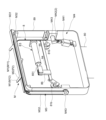
- FIG. 2 is a side view schematically showing the relative positional relationship between an EFEM equipped with a load port and its peripheral devices in an embodiment of the present invention.
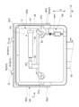
- FIG. 2 is a plan view in which the relative positional relationship shown in FIG. 1 is simplified.
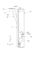
- FIG. 3 is a front view showing a load port in the same embodiment with a portion omitted. The figure which looked at the load port in the same embodiment from the back side.
- FIG. 3 is a rear view showing the load port in the same embodiment with some portions omitted.
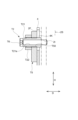
- FIG. 7 is a diagram corresponding to FIG. 6 showing a conventional connection switching mechanism. A view taken in the direction of arrow A in FIG. 5.
- FIG. 10 is a diagram corresponding to FIG. 9 illustrating a state in which the mapper is positioned at a mapping position.
- FIG. 3 is a front view of a load port equipped with a three-axis adjustment mechanism according to the same embodiment.
- FIG. 12 is a view of area C in FIG. 11 viewed from a predetermined angle.
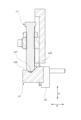
- FIG. 14 is a sectional view taken along line EE in FIG. 13.
- FIG. 14 is a sectional view taken along line FF in FIG. 13.
- FIG. 3 is a front view showing a load port in the same embodiment with a portion omitted.
- FIG. 16 is a diagram corresponding to FIG. 9 illustrating a state in which the mapper is positioned at a mapping position.
- FIG. 3 is a front view of a load port equipped with a three-axis adjustment mechanism according to the same embodiment.
- FIG. 12 is a view
- FIG. 16 is a sectional view taken along line a-a in FIG. 16.
- FIG. 17 is a view of the R region in FIG. 16 viewed from a predetermined angle.
- FIG. 17 is a view of the S area in FIG. 16 viewed from a predetermined angle.
- the load port attachment position adjustment mechanism T adjusts the attachment position of the load port 1 with respect to the wall surface 2F (front wall surface) of the transfer chamber 2 when the load port 1 is attached to the wall surface 2F (front wall surface) of the transfer chamber 2. It is a mechanism for adjustment.
- the load port 1 is used, for example, in the semiconductor manufacturing process, and as shown in FIGS. 1 and 2, it forms part of the wall surface 2F (front wall surface) of the transfer chamber 2 in a clean room, and is connected to the transfer chamber 2 and the FOUP. This is for loading and unloading objects to be transported such as wafers W into and out of transport containers 3 such as the above.
- the load port 1 constitutes a part of an EFEM (Equipment Front End Module) together with the transfer chamber 2, and functions as an interface portion between the transfer container 3 and the transfer chamber 2.
- EFEM Equipment Front End Module
- a FOUP 3 is provided with a FOUP main body 32 that can open the internal space 3S only rearward through the loading/unloading port 31, and a FOUP door 33 that can open/close the loading/unloading port 31.
- the FOUP 3 is a known FOUP in which multistage slots are provided inside, each slot is configured to accommodate wafers W as objects to be transported, and these wafers W are configured to be able to be taken in and out through the carry-in/out port 31.
- a flange portion 35 is provided on the upper surface of the FOUP main body 32 to be gripped by a device (for example, OHT: Over Head Transport) that automatically transports the transport container 3.
- the load port 1 includes a plate-shaped base frame 4 in which an opening 41 for opening the internal space 2S of the transfer chamber 2 is formed, and a base frame 4 that protrudes forward with respect to the base frame 4.
- a mounting table 5 provided in a substantially horizontal position
- a seating holding mechanism 6 that holds the FOUP 3 transferred from the outside on the mounting table 5, and a seating holding mechanism 6 that holds the FOUP 3 on the mounting table 5 in a substantially horizontal position and the object to be transported.
- the traction mechanism 7 that moves in the front-rear direction D to and from the delivery position, the load port door 8 that opens and closes the opening 41 of the base frame 4, and the load port door 8 moved to the door open position retreated toward the transfer chamber 2 side.
- the door opening/closing mechanism 9 opens the opening 41 of the base frame 4 by opening the opening 41 of the base frame 4.
- the base frame 4 is arranged in an upright position and has a substantially rectangular plate shape and has an opening 41 large enough to communicate with the loading/unloading port of the FOUP 3 placed on the loading table 5.
- FIG. 1 schematically shows the opening 41 of the base frame 4.
- the base frame 4 constitutes a part of the wall surface 2F (front wall surface) of the transfer chamber 2.
- a leg portion 42 having casters and an installation leg portion is provided at the lower end of the base frame 4.
- the mounting table 5 is provided on the top of a horizontal base 50 (supporting base) that is arranged in a substantially horizontal position at a position slightly above the center in the height direction of the base frame 4, and the FOUP main body 32 is attached to the base frame.
- the FOUP 3 can be placed in the direction facing the FOUP 4.
- the mounting table 5 is provided with a plurality of upwardly protruding protrusions 51, and these protrusions 51 are engaged with holes (not shown) formed on the bottom surface of the FOUP 3.
- the FOUP 3 is positioned on the mounting table 5.
- the seating holding mechanism 6 allows the FOUP 3 to be placed in a locked state by hooking a lock claw (not shown) provided on the placement table 5 to a locked portion (not shown) provided on the bottom of the FOUP 3. It is held on the table 5. Further, in the load port 1 of the present embodiment, the FOUP 3 can be placed in a state where it can be separated from the mounting table 5 by releasing the locked state of the lock claw with respect to the locked portion.
- the traction mechanism 7 transports the FOUP 3 on the loading table 5 at a seating position where the FOUP body 32 is spaced a predetermined distance from the load port door 8 and a position where the FOUP body 32 is brought into close contact with the load port door 8.
- the device is moved in the front-rear direction D between the object delivery position and the object delivery position.
- the traction mechanism 7 is configured using a slide rail (not shown) or the like that moves the mounting table 5 back and forth.
- the seating holding mechanism 6 and the traction mechanism 7 can also be considered as mechanisms included in the mounting table 5.
- the state in which the FOUP 3 is placed on the placement table 5 is simplified and shown as a state in which the bottom surface of the FOUP 3 is in contact with the top surface of the placement table 5.
- a plurality of protrusions 51 protruding above the top surface of the mounting table 5 support the FOUP 3 by engaging with bottomed holes formed in the bottom surface of the FOUP 3.
- the upper surface of the mounting table 5 and the bottom surface of the FOUP 3 do not contact each other, and a predetermined gap is defined between the upper surface of the mounting table 5 and the bottom surface of the FOUP 3.
- the load port door 8 has two positions: a fully closed position where the opening 41 of the base frame 4 is sealed (see FIG. 1), a door open position where the door is retreated toward the transfer chamber 2 from the fully closed position, and a door open position where the opening 41 of the base frame 4 is closed. It is movable between a fully open position and a fully open rearward position. As shown in FIG. 3, the load port door 8 includes a suction portion 81a that can be suctioned to the FOUP door 33, and an engagement claw 81b that can be engaged with an engagement hole (latch hole) of the FOUP door 33.
- an engaging part 81 is configured to be movable integrally with the FOUP door 33 between a fully closed position, a door open position, and a fully open position while maintaining the engaged state with the FOUP door 33 by the suction engaging part 81.
- the postures of the load port door 8 in the fully closed position and the door open position are set to be the same.
- the movement path of the load port door 8 between the fully open position and the fully closed position is such that the load port door 8 in the fully closed position is moved toward the transfer chamber 2 side to the door open position while maintaining its height position. (horizontal route), and a route (vertical route) in which the load port door 8 in the door open position is moved downward to the fully open position while maintaining its front-rear position.
- the FOUP door 33 held by the load port door 8 positioned at the door open position is attached to the base together with the load port door 8 so that the load port door 8 positioned at the door open position can move both vertically and horizontally. It is located at a position behind the frame 4 (a position completely separated from the FOUP main body 32 and disposed in the internal space 2S of the transfer chamber 2).
- the door opening/closing mechanism 9 communicates the internal space 3S of the FOUP 3 with the transfer chamber 2 through the opening 41 of the base frame 4 in the open state by moving the load port door 8 to the door open position or fully open position. It is.
- the door opening/closing mechanism 9 includes, for example, a movable block (not shown) that movably supports a support frame 80 (see FIGS. 4 and 5) that supports the load port door 8 in the front-rear direction D, or a movable block that supports the load port door 8 in the vertical direction H.
- the load port door 8 of this embodiment operates the engaging claw 81b of the suction engaging portion 81 to bring the FOUP door 33 and the FOUP main body 32 into an engaged state (latched state).
- a connection switching mechanism 83 is provided to release the FOUP door 33 from the FOUP main body 32 (unlatch state).
- the connection switching mechanism 83 is a mechanism that rotates an engaging claw 81b (latch key) that can be engaged with an unillustrated engaging hole (latch hole) provided in the FOUP door 33 within a predetermined angle range.
- FIGS. 4 and 5 are views in which a portion of the door cover 89 is removed to reveal the inside.
- the cylinder 85 is actuated to move the piston rod 851 from the first stroke position (1) to the first stroke position (1), as shown schematically in FIG.
- the engagement claw 81b rotates while being engaged with the engagement hole, and as a result, the FOUP door 33 is in a state where it can be removed from the FOUP main body 32 (unlatched state). (See figure (b)).
- the cylinder 85 is operated to move the piston rod 851 from the second stroke position (2) to the first stroke position (1).
- the engagement claw 81b rotates while being engaged with the engagement hole, and as a result, the FOUP door 33 can be placed in a state where it cannot be attached to or detached from the FOUP main body 32 (latched state) (see FIG. )reference).
- the engagement claw 81b is surely inserted and engaged into the engagement hole of the FOUP door 33, and the engaged state is maintained. It is necessary to rotate a certain engagement claw 81b.
- a cylinder bracket 86 provided at the tip of the piston rod 851 of the cylinder 85 is connected to the piston rod 851.
- dust may be generated due to contact between the stopper bolt 841 and the cylinder bracket 842, and the generated dust may flow into the transfer chamber 2.
- a stopper bolt 87 is provided inside a cylinder 85 that maintains high airtightness with an appropriate seal structure.
- the base end (end end) of the piston rod 851 comes into contact with the stopper bolt 87, so that the piston rod 851 moves forward and backward (specifically, moves in the backward direction).
- the rotation angle of the engaging claw 81b is determined by stopping the rotation of the engaging claw 81b that is linked to the forward and backward movement of the piston rod 851.
- an adjuster bolt is used as the stopper bolt 87, and the position of the tip of the adjuster bolt inside the cylinder 85 (the position in contact with the piston rod 851) is configured to be adjustable.
- the load port when the opening 41 of the base frame 4 is opened by the door opening/closing mechanism 9, the presence or absence of a wafer W in each slot 34 in the FOUP 3 at the transfer target object delivery position is detected. It is provided with a mapping mechanism M that maps information regarding the mounting state of the wafers W included therein.
- the mapping mechanism M detects the presence or absence of objects W to be transported, which are stored in multiple stages in the height direction H using multi-stage slots provided in the FOUP 3. It is equipped with a mapper M2 having a mapping sensor M1 (transmitter M11, receiver M12) at its tip, and a mapping arm M3 (mapping moving unit) that supports the mapper M2. The storage posture can be detected.
- the mapper M2 protrudes forward from a predetermined location of the mapping arm M3, as shown in FIGS. 8 and 9 (FIGS. 8 and 9 are a view in the direction A and a sectional view taken along the line BB in FIG. 5, respectively). They are arranged side by side in a pair on the left and right at a predetermined distance apart in the width direction W, and a mapping sensor M1 is attached to the tip. Note that in FIGS. 8 and 9, hatching (parallel diagonal lines) indicating the cut plane is omitted.
- the mapping sensor M1 includes a transmitter M11 (light emitting sensor) that emits a beam (line light) as a signal, and a receiver M12 (light receiving sensor) that receives the signal emitted from the transmitter M11.
- mapping sensor M1 by a transmitter and a reflection section that reflects the line light emitted from the transmitter toward the transmitter.
- the transmitter also functions as a receiver.
- the left and right spans of the mapping sensors M1 (M11, M12) are set so that the mapping sensors M1 (M11, M12), whose optical axes are oriented in the left and right horizontal directions, do not interfere with the transported object W that is the detection target during mapping processing. It is set to an appropriate value depending on the planar dimension of the object W to be transported.
- the mapping arm M3 maps the position of the mapper M2 in the front-rear direction D to the position shown in FIG.
- the wafer is moved between the position (P1) and the position shown in FIGS. 8 and 9, that is, the wafer mapping impossible position (P2) where the mapping sensor M1 cannot detect that the wafer W is accommodated in the FOUP3.
- FIG. 10 is a diagram corresponding to FIG. 9 showing a state in which the mapper M2 is positioned at the mapping position (P1).
- the mapping arm M3 of the present embodiment includes an upper frame portion M31 and a pair of left and right side frame portions M32 extending downward from both ends of the upper frame portion M31.
- the position of the mapper M2 can be changed between the mapping position (P1) and the wafer mapping impossible position by rotating within a predetermined angle range with the lower end of each side frame part M32 as the rotation center axis. (P2).
- each side frame portion M32 is rotatably attached to the side surface of a door cover 89 that covers peripheral parts of the load port door 8 from the transfer chamber 2 side.
- the mapping mechanism M of this embodiment includes a tilting mechanism M4 that tilts the entire mapping arm M3 about a pivot point at the attachment portion between the mapping arm M3 and the door cover 89.
- the tilting mechanism M4 includes a mapping arm driving cylinder M41 and a mapping mechanism having one end (lower end) connected to the tip (tip of the cylinder rod) of the mapping arm driving cylinder M41.
- mapping arm drive crank M42 It includes an arm drive crank M42 and a mapping arm pivot shaft M43 (corresponding to a pivot point) connected to the other end (upper end) of the mapping arm drive crank M42.
- the mapping arm driving cylinder M41 and the mapping arm driving crank M42 are arranged in the internal space of the door cover 89, and furthermore, the mapping arm pivot shaft M43 has a lower end portion (side frame portion) of the mapping arm M3.
- Most of the door cover 89 except for a predetermined area on the one end side that is fixed to the lower end of the door cover 89 is arranged in the internal space of the door cover 89.
- the mapping arm pivot shaft M43 is arranged in such a manner that the axial direction that coincides with the longitudinal direction extends in the width direction W of the load port 1, and has one end attached to the lower end of the mapping arm M3 (the lower end of the side frame M32). is fixed so as to be integrally rotatable, and a mapping arm driving crank M42 is integrally and rotatably fixed to the other end.
- the mounting position of the mapping arm pivot M43 is set at a position slightly lower than the center position in the height direction of the side frame part M32 (a position close to the center in the height direction of the load port door 8). (See Figure 5, etc.)
- the mapping arm drive crank M42 moves between the first position (1) and the second position (2) in conjunction with the forward and backward movement of the mapping arm drive cylinder M41. move between.
- the mapping arm drive crank M42 when the mapping arm drive crank M42 is in the first position (1), the mapper M2 can be positioned at the mapping position (P1).
- the mapping arm drive crank M42 when the mapping arm drive crank M42 is in the first position (1), the mapper M2 can be positioned at the mapping position (P1).
- FIG. 10 mapping arm drive mechanism
- mapping arm driving cylinder M41 when the mapping arm driving cylinder M41 is actuated to move the mapping arm driving crank M42 from the first position (1) to the second position (2), the The mapping arm pivot M43 rotates, and the mapping arm M3 tilts about the mapping arm pivot M43 by an amount corresponding to the rotation angle, making it impossible for the mapper M2 to perform wafer mapping from the mapping position (P1). It can be switched to position (P2).
- a first position detection sensor detects that the mapping arm driving crank M42 is in the first position (1)
- a first position detection sensor detects that the mapping arm driving crank M42 is in the second position (2).
- the mapper is equipped with a second position detection sensor (not shown) that detects this, and controls the driving of the mapping arm driving cylinder M41 based on these detection signals, and the tilting of the mapping arm M3 by the tilting mechanism M4.
- the position of M2 can be accurately positioned at the mapping position (P1) and the wafer unmappable position (P2).
- a counterweight (not shown) is provided below the lower end of each side frame portion M32 to stabilize the tilting operation of the mapping arm M3 by the tilting mechanism M4.
- the mapping arm M3 in this embodiment moves in the front-rear direction and up-down direction integrally with the door cover 89, and operates independently of the door opening/closing mechanism 9 by a tilting mechanism M4.
- the interior space of the door cover 89 is kept in a sealed state. Therefore, when the mapping arm driving cylinder M41 moves back and forth, particles are generated at the contact area between the mapping arm driving cylinder M41 and the mapping arm driving crank M42, and the contact area between the mapping arm driving crank M42 and the mapping arm pivot shaft M43. Even if this occurs, it can be confined within the interior space of the door cover 89. As a result, a situation in which these particles are discharged from the interior space of the door cover 89 to the interior space 2S of the transfer chamber 2 can be prevented and suppressed.
- the rotation center axis of the mapping arm was set at a position below the door cover 89, for example, at a predetermined position of the support frame 80 that supports the load port door 8, and the tilting mechanism was also arranged around it. Therefore, particles generated at the contact area between the mapping arm drive cylinder and the mapping arm drive crank or the contact area between the mapping arm drive crank and the mapping arm pivot shaft may be discharged into the internal space of the transfer chamber or There was a risk that it would fly up into the interior space of the building.
- the mapping arm M3 is tilted and driven by the tilting mechanism M4 of the present embodiment described above, such conventional problems can be solved.
- the rotation center axis of the mapping arm is located at a position lower than the door cover 89, for example, the support frame that supports the load port door 8.
- the arm length of the mapping arm M3 (the length from the rotation center axis M43 of the mapping arm M3 to the upper frame portion M31, which is the upper end of the mapping arm M3) is shorter than the conventional mode in which the mapping arm M3 is set at a predetermined position of 80. Therefore, compared to the conventional configuration, vibration during operation of the mapping arm M3 can be suppressed, contributing to improvement in mapping accuracy.
- the load port 1 of the present embodiment is provided on the mounting table 5 and injects an environmental gas (also referred to as purge gas), which is an appropriately selected gas such as nitrogen gas, inert gas, or dry air, into the FOUP 3 from the bottom side of the FOUP 3.
- an environmental gas also referred to as purge gas
- nitrogen gas or dry air is mainly used
- a bottom purge section can be provided that can replace the gas atmosphere inside the FOUP 3 with an environmental gas.
- the bottom purge unit mainly includes a plurality of nozzles (not shown) provided at predetermined locations on the mounting table 5, and the plurality of nozzles are used as a bottom purge injection nozzle for injecting a predetermined environmental gas and for discharging the gas atmosphere inside the FOUP 3. It functions as a bottom purge discharge nozzle.
- These plurality of nozzles can be connected by fitting into an inlet (injection port) and an outlet (exhaust port) (not shown) provided at the bottom of the FOUP 3.
- Environmental gas is supplied from the bottom purge injection nozzle to the internal space 3S of the FOUP 3 via the injection port, and the gas atmosphere in the internal space 3S of the FOUP 3 is supplied from the bottom purge discharge nozzle via the discharge port (this gas atmosphere is used for starting the purge process).
- the environmental gas is air or other non-air cleanliness, and after the predetermined time, it is a highly clean environmental gas filled in the internal space 3S of the FOUP 3. It is possible to perform processing.
- Such a load port 1 constitutes an EFEM together with a transfer chamber 2 equipped with a transfer robot 21 inside.
- a plurality (for example, three) of load ports 1 are arranged side by side on the front surface (front wall surface) 2F of the transfer chamber 2.
- the operation of the EFEM is controlled by the controller of the load port 1 (control unit 1C shown in FIG. 2) and the controller of the entire EFEM (control unit C shown in FIG. 1).
- a transfer robot 21 capable of transferring an object to be transferred, such as a wafer W, between the FOUP 3 on the load port 1 and the processing chamber R is provided.
- the transfer robot 21 includes, for example, an arm 212 that connects a plurality of link elements to each other so as to be horizontally rotatable, and has an object gripping section 211 (hand) at its tip, and an arm 212. It is provided with a running part that rotatably supports an arm base constituting the base end of the transport chamber 212 and runs in the width direction W of the transfer chamber 2 (the parallel direction of the load ports 1).
- the transfer robot 21 has a link structure (multi-joint structure) that changes shape between a folded state in which the arm length is minimum and an extended state in which the arm length is longer than in the folded state. It is possible to apply a transfer robot 21 in which a plurality of individually controllable hands 211 are arranged in multiple stages in the height direction at the tip of an arm 212.
- the transfer chamber 2 is configured so that the load port 1 and the processing chamber R are connected so that the internal space 2S is in a substantially sealed state.
- a downflow is formed in the internal space 2S of the transfer chamber 2, which is an airflow flowing from above to below. Therefore, even if there are particles contaminating the surface of the wafer W in the internal space 2S of the transfer chamber 2, the downflow pushes the particles downward and prevents the particles from adhering to the surface of the wafer W during transfer. It becomes possible to do so.
- the flow of gas in the transfer chamber 2 forming a downflow is schematically shown by arrows. It is also possible to configure an EFEM in which appropriate stations such as a buffer station and an aligner are arranged on the side surface of the transfer chamber 2 or in the internal space 2S of the transfer chamber 2.
- a plurality of processing chambers R are arranged in the width direction W on a wall surface 2B (rear wall surface) opposite to a wall surface 2F (front wall surface) in which the load port 1 is arranged in the transfer chamber 2 (in the illustrated example).
- three chambers) are arranged side by side, and each treatment chamber R is configured to perform different appropriate treatments. Examples of treatments performed in intermediate or post-processes of a semiconductor manufacturing process include a backlap process, a wafer stacking process, a dicing process, and the like.
- the operation of the processing chamber R is controlled by a controller for the processing chamber R (control unit RC shown in FIG. 1).
- the controller for the entire processing chamber R (control unit RC) and the controller for the entire EFEM (control unit C) are upper controllers of the control unit 1C of the load port 1.
- FIGS. 1 and 2 schematically show the relative positional relationship between the load port 1 and the transfer chamber 2, and the relative positional relationship between the EFEM equipped with the load port 1 and the transfer chamber 2 and the processing chamber R. It is a diagram.
- the load port attachment position adjustment mechanism T allows the load port 1 to be attached to the wall surface 2F of the transfer chamber 2 when the load port 1 is arranged and attached to the wall surface (front wall surface 2F) of the transfer chamber 2. This is a mechanism for adjusting the position.
- the load port mounting position adjustment mechanism T includes an , a Y-axis direction adjustment part T2 that adjusts the position (tilt position) of the load port 1 in the thickness direction D (front/back direction, depth direction) with respect to the wall surface (front wall surface 2F) of the transfer chamber 2; A Z-axis direction adjustment section T3 that adjusts the position of the load port 1 in the height direction H (vertical direction) with respect to the wall surface 2F), and a Z-axis direction adjustment section T3 that adjusts the position of the load port 1 in the height direction H (vertical direction) with respect to the A three-axis direction adjustment mechanism T4, in which the adjustment section T2 and the Z-axis direction adjustment section T3) are integrated, is arranged at the upper corner of the base frame 4.
- the load port mounting position adjustment mechanism T includes a load port guide part T5 that can be mounted (mounted) on the upper corner of the base frame 4, and is capable of moving forward and backward in the width direction W with respect to the load port guide part T5.
- the mobile body T31 is also provided.
- the X-axis direction moving body T11 is configured using an X-axis direction jack bolt T11 arranged in a posture with its axial direction aligned with the width direction W of the load port 1. be.
- the X-axis jack bolt T11 moves in a direction in which its tip is pressed against the side surface T51 of the load port guide portion T5.
- the X-axis jack bolt T11 is movably held by an X-axis jack bolt stay T12 provided at a position facing the side surface T51 of the load port guide portion T5.
- the X-axis direction jack bolt stay T12 is fixed to the base frame 4.
- the X-axis jack bolt stay T12 is provided with an X-axis nut T13 that is screwed onto the X-axis jack bolt T11, and the position of the X-axis jack bolt T11 can be fixed by the X-axis nut T13. can.
- the X-axis direction adjustment unit T1 moves the X-axis direction moving body T11 forward and backward in the width direction W of the load port 1, so that the entire load port 1 including the X-axis jack bolt stay T12 is guided by the load port. It can be moved in the width direction W relative to the portion T5.
- the entire load port 1 including the X-axis jack bolt stay T12 moves in the width direction W to the load port guide portion T5 (specifically, It is set to move in a direction away from the side surface T51).
- the Y-axis direction moving body T21 is constructed using a Y-axis direction adjustment bolt T21 arranged with its axial direction aligned with the thickness direction D of the load port 1.
- the Y-axis adjustment bolt T21 moves in a direction in which the tip thereof is pressed against the wall surface (front wall surface 2F) of the transfer chamber 2.
- the Y-axis direction adjustment bolt T21 is held by the load port guide portion T5 so as to be movable forward and backward.
- a threaded hole T50 into which the Y-axis direction adjustment bolt T21 is screwed is formed in the load port guide portion T5 so as to pass through the threaded hole T50 in the thickness direction. Further, a Y-axis nut T22 is provided in the load port guide portion T5 at a position overlapping the screw hole T50 in the thickness direction D, and a Y-axis direction adjustment bolt T21 is screwed into the Y-axis nut T22 and the screw hole T50. .
- By tightening the Y-axis nut T22 By tightening the Y-axis nut T22, movement of the Y-axis adjustment bolt T21 in the thickness direction D can be restricted and the position of the Y-axis adjustment bolt T21 can be fixed.
- a hollow cylindrical type that penetrates in the axial direction is used as the Y-axis adjustment bolt T21, and the load port mounting bolt T6 is inserted into the axial hollow part T21a of the Y-axis adjustment bolt T21. It is placed.
- the total length of the load port mounting bolt T6 is longer than the total length of the Y-axis adjustment bolt T21, and the tip of the load port mounting bolt T6 is attached to a mounting hole formed in the wall surface (front wall surface 2F) of the transfer chamber 2. 2t directly or via a nut to allow screwing (see FIG. 14).
- the head of the load port mounting bolt T6 is set so as to hit one end (front end) of the Y-axis adjustment bolt T21.
- the Y-axis direction adjustment unit T2 moves the Y-axis direction movable body T21 forward and backward in the thickness direction D of the load port 1, thereby adjusting the entire load port 1 with respect to the wall surface (front wall surface 2F) of the transfer chamber 2. It can be moved in the thickness direction D (depth direction, tilt direction).
- the entire load port 1 is set to move in the direction away from the wall surface (front wall surface 2F) of the transfer chamber 2 in the thickness direction D. are doing.
- the Z-axis moving body T31 is constructed using a Z-axis jack bolt T31 arranged with its axial direction aligned with the height direction H of the load port 1.
- the Z-axis jack bolt T31 is movably held by a Z-axis jack bolt stay T32 provided at a position facing the downward surface T52 of the load port guide portion T5.
- the Z-axis direction jack bolt stay T32 is fixed to the base frame 4.
- the head of the Z-axis jack bolt T31 pushes up the Z-axis jack bolt stay T32, and the entire base frame 4 that fixes the Z-axis jack bolt stay T32, and by extension the entire load port 1, moves upward.
- a Z-axis nut T33 that is screwed onto the Z-axis jack bolt T31 is provided on the downward surface T52 of the load port guide portion T5, and the Z-axis nut T33 extends in the height direction H of the Z-axis jack bolt T31.
- the position of the Z-axis jack bolt T31 can be fixed by restricting the movement of the Z-axis jack bolt T31.
- the Z-axis adjustment unit T3 moves the Z-axis moving body T31 forward and backward in the height direction H of the load port 1, thereby adjusting the entire load port 1 including the Z-axis jack bolt stay T32 to the load port. It can be moved in the height direction H relative to the guide portion T5.
- the entire load port 1 including the Z-axis jack bolt stay T32 moves to the load port guide portion T5 in the height direction H. It is set to move in the direction closer to (upward).
- the X-axis jack bolt stay T12 and the Z-axis jack bolt stay T32 are integrally formed and fixed to the base frame 4 (see the difference between FIGS. 12 and 13).
- the load port guide portion T5 is a plate-shaped member having a side surface T51 that is in contact with the tip of the X-axis moving body T11, and a downward facing surface T52 that has an insertion hole T53 into which the Z-axis moving body T31 can be inserted. It is.
- load port guide portions T5 having different thicknesses at the center portion in the width direction W are applied, and the tip of the X-axis direction movable body T11 is applied to the relatively thick portion.
- a contact point and a formation point of the insertion hole T53 are set.
- a plate mounting bolt hole T54 into which a plate mounting bolt T7 for attaching the load port guide portion T5 to the base frame 4 can be inserted is formed in a relatively thick portion of the load port guide portion T5. .
- the plate mounting bolt hole T54 is set to a size that allows the plate mounting bolt T7 to be inserted with sufficient play.
- the plate mounting bolt holes T54 are formed at a plurality of locations (two locations in the illustrated example) at a predetermined pitch in the height direction H.
- the plate mounting bolt T7 is inserted into the plate mounting bolt hole T54 with the plate mounting bolt hole T54 covered and sealed by the plate cover T8, and the tip of the plate mounting bolt T7 is formed on the base frame 4.
- the load port guide portion T5 can be fixed to the base frame 4 by screwing into the fixing hole 4t for the mounting bolt.
- a threaded hole T50 into which the Y-axis adjustment bolt T21 is screwed is formed in a relatively thin portion of the load port guide portion T5.
- a predetermined area of the load port guide part T5 including the location where the screw hole T50 is formed does not directly overlap the base frame 4 due to the notch 4K formed in the base frame 4, but faces the wall surface (front wall surface 2F) of the transfer chamber 2. I will do it.
- the load port mounting position adjustment mechanism T has a three-axis direction adjustment mechanism T4 as a main element that integrates such an X-axis direction adjustment section T1, a Y-axis direction adjustment section T2, and a Z-axis direction adjustment section T3. , are arranged at both corners of the upper part of the base frame 4, and the mounting position of the load port 1 with respect to the wall surface (front wall surface 2F) of the transfer chamber 2 can be adjusted by going through the procedure described below at each location. Can be done.
- the plate mounting bolt T7, the X-axis jack bolt T11 which is the X-axis moving body T11, and the Z-axis jack bolt T31 which is the Z-axis moving body T31 are first prepared. Leave it loose. The load port 1 in such a preparatory state is moved to a position close to the wall surface (front wall surface 2F) of the transfer chamber 2 with the base frame 4 in a vertical posture. Next, insert the load port mounting bolt T6 into the shaft hollow part T21a of the Y-axis adjustment bolt T21 (it may be inserted in advance), and insert the tip directly into the mounting hole 4t of the base frame 4. Or insert it through a nut and screw it together.
- the load port mounting bolts T6 are loosened, and the load port guide portion T5 is aligned with the base frame 4 in the width direction W (X-axis direction), thickness direction D (Y-axis direction), and height. It is important to be able to move several millimeters in each direction H (Z-axis direction).
- the plate mounting bolt T7 is screwed into the plate mounting bolt fixing hole 4t formed in the base frame 4 and firmly tightened.
- the load port guide portion T5 can be fixed to the base frame 4.
- the Y-axis direction adjustment section T2 performs Y-axis direction mounting position adjustment processing. Specifically, when a tightening force is applied to the Y-axis adjustment bolt T21, the entire load port 1 moves in a direction away from the wall surface (front wall surface 2F) of the transfer chamber 2, and the Y-axis adjustment bolt T21 When an operating force is applied to loosen the tightening, the entire load port 1 moves in a direction approaching the wall surface (front wall surface 2F) of the transfer chamber 2.
- the position of the entire load port 1 in the thickness direction D relative to the wall surface (front wall surface 2F) of the transfer chamber 2 can be adjusted in units of several mm.
- the position of the load port 1 at the time of initial setting before Y-axis direction adjustment processing is set as a reference position, and it can be moved up to +2 mm (2 mm forward) in the Y-axis direction (front-back direction D) from the reference position. It is composed of After adjusting the position in the Y-axis direction, the position of the Y-axis adjustment bolt T21 is fixed by applying an operating force to tighten the Y-axis nut T22 provided on the load port guide portion T5.
- Z-axis direction mounting position adjustment processing is performed by the Z-axis direction adjustment section T3. Specifically, when a tightening operation force is applied to the Z-axis jack bolt T31, the entire load port 1 including the Z-axis jack bolt stay T32 is raised against the wall surface of the transfer chamber 2 (front wall surface 2F). direction and applies an operating force to loosen the tightening to the Z-axis jack bolt T31, the entire load port 1 including the Z-axis jack bolt stay T32 is moved against the wall surface of the transfer chamber 2 (front wall surface 2F). to move downward.
- the position of the entire load port 1 in the height direction H relative to the wall surface (front wall surface 2F) of the transfer chamber 2 can be adjusted in units of several mm.
- the position of the load port 1 after the Y-axis direction adjustment processing is set as the Z-axis direction reference position, and the position is within a range of plus or minus 5 mm (10 mm) in the Z-axis direction (vertical direction H) from the Z-axis direction reference position. (within range).
- the position of the Z-axis jack bolt T31 is fixed by applying an operating force to tighten the Z-axis nut T33 provided on the load port guide part T5.
- the X-axis direction adjustment section T1 performs the X-axis direction mounting position adjustment process. Specifically, when a tightening operation force is applied to the X-axis jack bolt T11, the entire load port 1 including the X-axis jack bolt stay T12 is temporarily fixed to the wall surface (front wall surface 2F) of the transfer chamber 2. When the load port guide portion T5 is moved to either the left or right side (the left side in the illustrated example) and an operating force is applied to loosen the X-axis jack bolt T11, the entire load port 1 is moved. It moves to the other side of the left side or the right side (right side in the illustrated example) with respect to the load port guide part T5.
- the position of the entire load port 1 in the width direction W with respect to the wall surface (front wall surface 2F) of the transfer chamber 2 can be adjusted in units of several mm.
- the position of the load port 1 after the Z-axis direction adjustment process is taken as the X-axis reference position, and the position is within a range of plus or minus 5 mm (within a range of 10 mm) in the X-axis direction (horizontal direction) from the X-axis reference position. (inside) is configured to be movable.
- the position of the X-axis jack bolt T11 is fixed by applying an operating force to tighten the X-axis nut T13 provided on the X-axis jack bolt stay T12.
- the entire load port 1 relative to the wall surface (front wall surface 2F) of the transfer chamber 2 is adjusted.
- the mounting position in three axes can be adjusted.
- the order of mounting position adjustment is not limited to i) Y-axis mounting position adjustment processing, ii) Z-axis mounting position adjustment processing, and iii) X-axis mounting position adjustment processing, but may be performed in any appropriate order. I don't mind.
- the three-axis direction adjustment mechanisms T4 are provided at both ends of the upper stage of the base frame 4, and each of the three-axis direction adjustment mechanisms T4 is configured to be adjustable individually. Therefore, the operator is forced to adjust the position of the load port 1 in the height direction H by accessing the jack bolt provided in a recessed position at the bottom of the base frame 4 in a crawling position, as in the past. To be able to smoothly adjust the mounting position of the load port 1 by accessing the 3-axis direction adjustment mechanism T4 in a standing posture without having to worry about it, improving work efficiency and shortening the installation work time. Can be done.
- the three-axis direction adjustment mechanism T4 is attached to the wall surface (front wall surface 2F) of the transfer chamber 2 using the mounting hole 2t whose formation location is specified by SEMI standards in the wall surface (front wall surface 2F) of the transfer chamber 2.
- the mounting hole 2t whose formation location is specified by SEMI standards in the wall surface (front wall surface 2F) of the transfer chamber 2.
- the load port mounting position adjustment mechanism T there is no need to arrange the height position adjustment jack bolt in the lower part of the base frame 4 in a posture in which it protrudes lower than the surrounding parts. Therefore, for example, when moving the load port 1 alone or the entire EFEM with the load port 1 attached to the transfer chamber 2 using a forklift, the claws of the forklift may come into contact with the exposed part (lower end part) of the height adjustment jack bolt. , the situation of falling due to getting caught, etc. does not occur, and safety risks can be reduced.
- the load port mounting position adjustment mechanism T has a leg portion L1 provided at the lower part of the load port 1 and a wall surface (front wall surface 2F) of the transfer chamber 2.
- the load port 1 can be installed in accordance with the SEMI standard by placing the leg portion L1 on the leg receiving portion L2.
- FIG. 16 is a front view of the lower half of the load port 1
- FIG. 17 is an enlarged view of the Q area in FIG. 16 with some parts removed
- FIG. 18 is a -a line sectional view.
- a block-shaped member in which a groove L21 into which the lower end of the leg portion L1 is fitted is continuously formed in the width direction W is used as the leg receiving portion L2.
- a jack bolt is illustrated in FIGS. 17 and 18 as the leg portion L1
- a simple rod-shaped part may also be used.
- the height of the upward surface is set to the groove L21. Different values are applied before and after.
- the upward facing surface on the front side of the groove L21 (the upward facing surface L22 on the front side) is set at a lower position than the upward facing surface on the rear side of the groove L21 (the upward facing surface L23 on the rear side). Therefore, the depth from the front upward surface L22 to the bottom of the groove L21 is shallower than the depth from the rear upward surface L23 to the bottom of the groove L21.
- leg receiving portion L2 is fixed to a lower mounting bracket 2U fixed to the lower part of the wall surface (front wall surface 2F) of the transfer chamber 2.
- leg portions L1 are provided at the lower end portions of both left and right sides of the load port 1, and leg receiving portions L2 are provided at positions corresponding to the leg portions L1 in the lower mounting bracket 2U.
- the load port attachment position adjustment mechanism T allows the operator to attach the load port 1 to the wall surface (front wall surface 2F) of the transfer chamber 2. It is provided with a handle K that can be gripped and applied with a pressing force to move the entire load port 1 toward the wall surface (front wall surface 2F) of the transfer chamber 2.
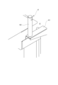
- FIG. 19 is a perspective view of the R area in FIG. 16 viewed from one side of the load port 1
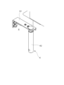
- FIG. 20 is a perspective view of the S area in FIG. 16 viewed from the other side of the load port 1.
- FIG. 19 and 20 the peripheral parts of the handle part K are shown in a partially removed state.
- the handle part K has a base end fixed to the base frame 4, and includes a handle receiving part K1 extending toward the front, and a rod-shaped handle body part K2 supported in an upright position at the tip of the handle receiving part K1.
- the handle main body part K2 is stored in the usage position in which it protrudes upward relative to the handle receiving part K1 (see FIG. 19) and in the internal space of the cover 50 (see FIG. 16) disposed below the handle receiving part K1. It is supported by the handle receiving part K1 so that the position can be changed between the stored position (see FIG. 20) and the stored position (see FIG. 20).
- a pair of left and right handles K are provided on the base frame 4 at positions sandwiching the mounting table 5 in the width direction W.
- the transfer After moving the load port 1 by appropriate means from the front side (front) of the chamber 2 to a position approaching the wall surface (front wall surface 2F), the operator must move the handle body supported in the usage position by the handle receiving part K1. Grip part K2 and apply an operating force to push it toward the wall surface (front wall surface 2F) of the transfer chamber 2.
- the entire load port 1 can be moved toward the wall surface (front wall surface 2F) of the transfer chamber 2, and the leg portion L1 provided at the lower part of the load port 1 can be installed in the leg receiving portion L2.
- the leg receiving portion L2 by providing a step on the upward surfaces L22 and L23 of the leg receiving portion L2 and setting the front upward surface L22 with the groove L21 as a boundary at a lower position than the rear upward surface L23, the leg There is no need to temporarily tilt or lift the entire load port 1 in order to place L1 on the leg holder L2, and the load port 1 can be loaded until the lower end of the leg L1 fits into the groove L21 of the leg holder L2.
- the leg portion L1 By pushing the entire port 1, the leg portion L1 can be smoothly placed on the leg receiving portion L2.
- the handle main body part K2 is changed from the use position (see FIG. 19) to the stored position (see FIG. 20) at an appropriate timing after the leg part L1 has been placed on the leg receiving part L2.
- the handle main body part K2 can be stored in the internal space of the cover 50, and it is possible to prevent problems such as the handle part K interfering with other parts after the load port installation work.
- the leg receiving groove L21 formed on the upper surface of the block-shaped leg receiving part L2 is located at the front side of the leg receiving groove L21. Since the upward surface L22 is set at a lower position than the upward surface L23 on the rear side of the leg receiving groove L21, when the operator attaches the load port 1 to the wall surface of the transfer chamber 2 (front wall surface 2F), When the operator applies an operating force to push the load port 1 toward the wall surface (front wall surface 2F) of the transfer chamber 2, the leg portion L1 passes through the upward facing surface L22 on the front side of the leg receiving groove L21.
- the leg part L2 fits smoothly into the leg receiving groove L21, and the leg part L1 hits the part of the main body of the leg receiving part L2 on the rear side of the leg receiving groove L21, so that the leg part L1 is not inserted into the wall surface of the transfer chamber 2 (front wall surface 2F). It is possible to prevent the leg L1 from moving toward the leg receiving groove L21 and maintain the state in which the leg L1 is fitted into the leg receiving groove L21. Therefore, even if the load port 1 is large and heavy and has been developed to accommodate large wafers (large substrates), the entire load port must be tilted when attached to the wall surface (front wall surface 2F) of the transfer chamber 2. It is possible to avoid risks (such as the load port 1 falling over) due to being forced to do the work.
- the leg portion L1 is received (supported) by the leg receiving portion L2
- the work location of the load port 1 during installation which was previously unclear, can be clarified, and it is possible to clarify who is working on the load port 1. Even if there is a problem, the installation work can be easily carried out.
- the load port mounting position adjustment mechanism T includes a handle K extending horizontally from the base frame 4 within the reach of the operator.
- the load port 1 is equipped with a large loading table 5 on which a large FOUP for storing wafers such as Even if the load port 1 is large and heavy and cannot reach the base frame 4, the operator must grasp the handle K and use the operating force to push the load port 1 toward the wall surface (front wall surface 2F) of the transfer chamber 2. can be provided, and the installation work to the wall surface (front wall surface 2F) of the transfer chamber 2 can be performed smoothly and appropriately.
- the present invention is not limited to the embodiments described above.
- the X-axis direction adjustment section, the Y-axis direction adjustment section, and the Z-axis direction adjustment section each use the screwing forward and backward movements of bolts, but the types of bolts are not particularly limited.
- the three-axis direction adjustment mechanism may be attached to the wall using the mounting holes (holes indicated by symbols 2t and (2c) in FIG. 3) formed in the middle of the wall of the transfer chamber.
- the SEMI standard requires that attachment holes be formed in the wall surface of the transfer chamber at predetermined locations in the upper, middle, and lower tiers.
- the position adjustment mechanism according to the present invention can be attached to the wall surface of the transfer chamber by using the upper and middle holes according to the SEMI standard.
- the transport container is not limited to a FOUP, and may be a container other than a FOUP, such as a FOSB (Front Opening Shipping Box) or a cassette.
- FOSB Front Opening Shipping Box
- cassette a container other than a FOUP, such as a FOSB (Front Opening Shipping Box) or a cassette.
- the load port according to the present invention can be used as a part of the EFEM, and it can also be applied to a transfer device other than the EFEM, and in that case, the load port for the transfer chamber can also be used as a part of the EFEM.
- the mounting position adjustment mechanism of the present invention can be applied to improve the mounting workability.
- a wafer is used as an example of the object to be transported, but the object to be transported may also be a square substrate including a reticle, a liquid crystal transport object, a glass transport object, a ring frame wafer, a culture plate, a culture container, a dish, etc. , or a petri dish.
Landscapes
- Container, Conveyance, Adherence, Positioning, Of Wafer (AREA)
Priority Applications (4)
| Application Number | Priority Date | Filing Date | Title |
|---|---|---|---|
| KR1020257001402A KR20250040629A (ko) | 2022-07-19 | 2023-06-30 | 로드 포트 설치 위치 조정 기구 |
| US18/995,509 US20260018447A1 (en) | 2022-07-19 | 2023-06-30 | Load port mounting position adjustment mechanism |
| JP2024535000A JPWO2024018872A1 (https=) | 2022-07-19 | 2023-06-30 | |
| CN202380054204.0A CN119563230A (zh) | 2022-07-19 | 2023-06-30 | 装载端口安装位置调整机构 |
Applications Claiming Priority (2)
| Application Number | Priority Date | Filing Date | Title |
|---|---|---|---|
| JP2022-114694 | 2022-07-19 | ||
| JP2022114694 | 2022-07-19 |
Publications (1)
| Publication Number | Publication Date |
|---|---|
| WO2024018872A1 true WO2024018872A1 (ja) | 2024-01-25 |
Family
ID=89617690
Family Applications (1)
| Application Number | Title | Priority Date | Filing Date |
|---|---|---|---|
| PCT/JP2023/024330 Ceased WO2024018872A1 (ja) | 2022-07-19 | 2023-06-30 | ロードポート取付位置調整機構 |
Country Status (6)
| Country | Link |
|---|---|
| US (1) | US20260018447A1 (https=) |
| JP (1) | JPWO2024018872A1 (https=) |
| KR (1) | KR20250040629A (https=) |
| CN (1) | CN119563230A (https=) |
| TW (1) | TW202422762A (https=) |
| WO (1) | WO2024018872A1 (https=) |
Citations (5)
| Publication number | Priority date | Publication date | Assignee | Title |
|---|---|---|---|---|
| JP2000332079A (ja) * | 1999-05-18 | 2000-11-30 | Tdk Corp | 半導体製造装置用ロードポート、ロードポート取り付け機構及びロードポート取り付け方法 |
| JP2001526458A (ja) * | 1997-09-03 | 2001-12-18 | アシスト テクノロジーズ インコーポレイテッド | ティルトアンドゴー方式のロードポート・インタフェース整列システム |
| JP2002134582A (ja) * | 2000-10-11 | 2002-05-10 | Ind Technol Res Inst | ウェハーロードポートの位置決め装置と方法 |
| JP2003092323A (ja) * | 2001-09-17 | 2003-03-28 | Dainippon Screen Mfg Co Ltd | ロードポート装置及びこの装置と上位装置との取り付け機構 |
| JP2019536272A (ja) * | 2016-11-10 | 2019-12-12 | アプライド マテリアルズ インコーポレイテッドApplied Materials,Incorporated | 改善されたロードポートバックプレーンのためのシステム、装置、及び方法 |
Family Cites Families (2)
| Publication number | Priority date | Publication date | Assignee | Title |
|---|---|---|---|---|
| JPS5910019U (ja) | 1982-07-12 | 1984-01-21 | 日産自動車株式会社 | 液面計測装置 |
| JPS5988076U (ja) | 1982-12-07 | 1984-06-14 | 三菱電機株式会社 | 乗客コンベヤの欄干装置 |
-
2023
- 2023-06-30 KR KR1020257001402A patent/KR20250040629A/ko active Pending
- 2023-06-30 CN CN202380054204.0A patent/CN119563230A/zh active Pending
- 2023-06-30 JP JP2024535000A patent/JPWO2024018872A1/ja active Pending
- 2023-06-30 US US18/995,509 patent/US20260018447A1/en active Pending
- 2023-06-30 WO PCT/JP2023/024330 patent/WO2024018872A1/ja not_active Ceased
- 2023-07-19 TW TW112126932A patent/TW202422762A/zh unknown
Patent Citations (5)
| Publication number | Priority date | Publication date | Assignee | Title |
|---|---|---|---|---|
| JP2001526458A (ja) * | 1997-09-03 | 2001-12-18 | アシスト テクノロジーズ インコーポレイテッド | ティルトアンドゴー方式のロードポート・インタフェース整列システム |
| JP2000332079A (ja) * | 1999-05-18 | 2000-11-30 | Tdk Corp | 半導体製造装置用ロードポート、ロードポート取り付け機構及びロードポート取り付け方法 |
| JP2002134582A (ja) * | 2000-10-11 | 2002-05-10 | Ind Technol Res Inst | ウェハーロードポートの位置決め装置と方法 |
| JP2003092323A (ja) * | 2001-09-17 | 2003-03-28 | Dainippon Screen Mfg Co Ltd | ロードポート装置及びこの装置と上位装置との取り付け機構 |
| JP2019536272A (ja) * | 2016-11-10 | 2019-12-12 | アプライド マテリアルズ インコーポレイテッドApplied Materials,Incorporated | 改善されたロードポートバックプレーンのためのシステム、装置、及び方法 |
Also Published As
| Publication number | Publication date |
|---|---|
| TW202422762A (zh) | 2024-06-01 |
| US20260018447A1 (en) | 2026-01-15 |
| KR20250040629A (ko) | 2025-03-24 |
| JPWO2024018872A1 (https=) | 2024-01-25 |
| CN119563230A (zh) | 2025-03-04 |
Similar Documents
| Publication | Publication Date | Title |
|---|---|---|
| KR101302812B1 (ko) | 처리 장치 및 처리 방법 | |
| US9670010B2 (en) | Substrate loading and unloading station with buffer | |
| US6364593B1 (en) | Material transport system | |
| JP6455239B2 (ja) | ドア開閉装置 | |
| JP7082274B2 (ja) | ロードポート、及びロードポートにおけるマッピング処理方法 | |
| TWI776016B (zh) | 薄板狀基板保持裝置及具備保持裝置之搬送機器人 | |
| EP1793420B1 (en) | Attaching and removing unit of lid for wafer carrier | |
| US5806574A (en) | Portable closed container | |
| CN105556652B (zh) | 使传输中衬底居中的处理设备 | |
| JP7148825B2 (ja) | ロードポート及びロードポートを備える基板搬送システム | |
| US6869263B2 (en) | Substrate loading and unloading station with buffer | |
| JP2016164929A (ja) | ドア開閉装置、搬送装置、ソータ装置、収納容器の開放方法 | |
| KR101650530B1 (ko) | 덮개 개폐 장치 | |
| US20150071739A1 (en) | Efem | |
| US11430679B2 (en) | Semiconductor manufacturing apparatus | |
| JP2020004839A (ja) | 半導体ワーク搬送装置 | |
| WO2024018872A1 (ja) | ロードポート取付位置調整機構 | |
| JPH1092905A (ja) | 処理装置 | |
| KR100922051B1 (ko) | 반도체 처리 장치에 있어서의 포트 구조 | |
| US10403529B2 (en) | Carrier transport device and carrier transport method | |
| KR100717990B1 (ko) | 반도체 자재 처리를 위한 이송 시스템 | |
| CN111164745A (zh) | 盒开启器 | |
| JP3974992B2 (ja) | 基板収納容器の蓋開閉装置および基板搬入搬出装置 | |
| JP3787755B2 (ja) | 処理システム | |
| US20040126206A1 (en) | Mini-environment system and operating method thereof |
Legal Events
| Date | Code | Title | Description |
|---|---|---|---|
| 121 | Ep: the epo has been informed by wipo that ep was designated in this application |
Ref document number: 23842798 Country of ref document: EP Kind code of ref document: A1 |
|
| WWE | Wipo information: entry into national phase |
Ref document number: 202380054204.0 Country of ref document: CN Ref document number: 18995509 Country of ref document: US |
|
| WWE | Wipo information: entry into national phase |
Ref document number: 2024535000 Country of ref document: JP |
|
| NENP | Non-entry into the national phase |
Ref country code: DE |
|
| WWP | Wipo information: published in national office |
Ref document number: 202380054204.0 Country of ref document: CN |
|
| WWP | Wipo information: published in national office |
Ref document number: 1020257001402 Country of ref document: KR |
|
| 122 | Ep: pct application non-entry in european phase |
Ref document number: 23842798 Country of ref document: EP Kind code of ref document: A1 |
|
| WWP | Wipo information: published in national office |
Ref document number: 18995509 Country of ref document: US |