WO2024009669A1 - コンベヤシステム及びコンベヤシステムの制御方法 - Google Patents
コンベヤシステム及びコンベヤシステムの制御方法 Download PDFInfo
- Publication number
- WO2024009669A1 WO2024009669A1 PCT/JP2023/021108 JP2023021108W WO2024009669A1 WO 2024009669 A1 WO2024009669 A1 WO 2024009669A1 JP 2023021108 W JP2023021108 W JP 2023021108W WO 2024009669 A1 WO2024009669 A1 WO 2024009669A1
- Authority
- WO
- WIPO (PCT)
- Prior art keywords
- conveyor
- conveyor line
- article
- line
- received
- Prior art date
- Legal status (The legal status is an assumption and is not a legal conclusion. Google has not performed a legal analysis and makes no representation as to the accuracy of the status listed.)
- Ceased
Links
Images







Classifications
-
- B—PERFORMING OPERATIONS; TRANSPORTING
- B65—CONVEYING; PACKING; STORING; HANDLING THIN OR FILAMENTARY MATERIAL
- B65G—TRANSPORT OR STORAGE DEVICES, e.g. CONVEYORS FOR LOADING OR TIPPING, SHOP CONVEYOR SYSTEMS OR PNEUMATIC TUBE CONVEYORS
- B65G47/00—Article or material-handling devices associated with conveyors; Methods employing such devices
- B65G47/52—Devices for transferring articles or materials between conveyors i.e. discharging or feeding devices
- B65G47/53—Devices for transferring articles or materials between conveyors i.e. discharging or feeding devices between conveyors which cross one another
-
- B—PERFORMING OPERATIONS; TRANSPORTING
- B65—CONVEYING; PACKING; STORING; HANDLING THIN OR FILAMENTARY MATERIAL
- B65G—TRANSPORT OR STORAGE DEVICES, e.g. CONVEYORS FOR LOADING OR TIPPING, SHOP CONVEYOR SYSTEMS OR PNEUMATIC TUBE CONVEYORS
- B65G47/00—Article or material-handling devices associated with conveyors; Methods employing such devices
- B65G47/52—Devices for transferring articles or materials between conveyors i.e. discharging or feeding devices
- B65G47/64—Switching conveyors
Definitions
- the present invention relates to a conveyor system and a method of controlling the conveyor system.
- a conveyor system having a controller is known (for example, see Patent Document 1). When the rotating conveyor receives an article to be conveyed from the first conveyor line or the second conveyor line, the controller operates the rotating conveyor to rotate around the vertical axis and deliver the article to the third conveyor line.
- the swivel conveyor After receiving an article from one of the first conveyor line and the second conveyor line, the swivel conveyor needs to pivot when receiving the next article from the other conveyor line.
- Each of the first conveyor line and the second conveyor line is provided with a sensor that detects the articles being conveyed.
- the controller rotates the revolving conveyor to a state in which the revolving conveyor can receive the article from the first conveyor line or the second conveyor line based on the detection result of the article by the sensor.
- An object of the present invention is to provide a conveyor system and a method for controlling the conveyor system that can suppress a decrease in article conveyance efficiency.
- a conveyor system is rotatable around a vertical axis, and has a first conveyor line, a second conveyor line, and a third conveyor line that convey articles, and is capable of rotating from the first conveyor line or the second conveyor line.
- a revolving conveyor that receives an article and delivers the article to a third conveyor line; a first state in which the revolving conveyor is rotated about a vertical axis to be able to receive the article from the first conveyor line; and a first state in which the article can be received from the second conveyor line.
- a controller that determines whether the orbiting conveyor has received an article from the first conveyor line or the second conveyor line after the orbiting conveyor has passed the article to the third conveyor line;
- the revolving conveyor is made to stand by in the first state or the second state based on performance data indicating.
- a method for controlling a conveyor system is such that a first conveyor line, a second conveyor line, and a third conveyor line that convey articles are rotatable around a vertical axis, and the first conveyor line or the second conveyor line
- a method for controlling a conveyor system comprising: a revolving conveyor that receives an article from a conveyor line and delivers the article to a third conveyor line; and the performance data indicating which of the second conveyor lines the article was received from, the swing conveyor is placed in the first state in which the article can be received from the first conveyor line or in the first state in which the article can be received from the second conveyor line. This includes waiting in two states.
- the revolving conveyor waits facing the direction of the conveyor line where the next article is likely to be received, so that the article is not placed on the conveyor line.
- the conveyance time can be shortened by the amount of turning time without stagnation. Thereby, it is possible to suppress a decrease in the conveyance efficiency of the conveyor system.
- the controller compares the number of times the revolving conveyor receives articles from the first conveyor line and the number of times the revolving conveyor receives articles from the second conveyor line based on the performance data.
- the controller is configured to remove the articles from the first conveyor line within the predetermined number of times that the revolving conveyor has received the articles, or the number of times that the revolving conveyor has received the articles within the predetermined period.
- the number of times the item has been received may be compared to the number of times the item has been received from the second conveyor line.
- the standby state of the revolving conveyor can be changed according to changes in the conveyance situation.
- the controller when the rotating conveyor receives articles from either the first conveyor line or the second conveyor line consecutively for a predetermined number of times or more, the controller causes the rotating conveyor to rotate for a predetermined number of times or for a predetermined period of time. Regardless of whether the conveyor has received articles many times or not, the first conveyor line or the second conveyor line from which the revolving conveyor has received articles consecutively more than a predetermined number of times may be identified. According to this aspect, it is possible to accurately predict the conveyor line that is likely to be the receiving destination of the next article, and it is possible to further suppress a decrease in the conveyance efficiency of the conveyor system.
- the settings may be changeable a predetermined number of times or for a predetermined period. According to this aspect, the sensitivity to changes in the conveyance situation can be adjusted.
- the controller includes a storage unit that stores performance data, and when the revolving conveyor receives an article from the first conveyor line or the second conveyor line, the controller Information indicating from which conveyor line the article was received may be stored in the storage unit in chronological order for each article as performance data. According to this aspect, performance data can be collected during actual operation.
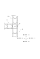
- FIG. 1 is a diagram showing an example of a conveyor system according to a first embodiment. It is a figure which shows the 1st state of a turning conveyor. It is a figure which shows the 2nd state of a turning conveyor.
- FIG. 3 is a diagram illustrating standby processing according to the first embodiment. It is a figure showing the first number of times of reception and the second number of times of reception according to the first embodiment. It is a flowchart of standby processing in the control method of the conveyor system concerning a 1st embodiment. It is a figure showing the state of operation of the turning conveyor concerning a 1st embodiment. It is a figure showing the state of operation of the turning conveyor concerning a 1st embodiment.
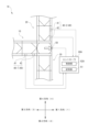
- FIG. 1 is a diagram showing an example of a conveyor system 1 according to the first embodiment.
- the conveyor system 1 transports a container containing an object to be transported (hereinafter referred to as "article F").
- the conveyor system 1 carries the article F into a stocker, or carries the article F out from the stocker and conveys it to a processing device.
- the article F may be, for example, a FOUP (Front Opening Unified Pod) that accommodates a wafer processed in a semiconductor manufacturing device or a liquid crystal manufacturing device, or a reticle pod that accommodates a reticle used in a semiconductor manufacturing device or a liquid crystal manufacturing device.
- the above-mentioned processing apparatuses include, for example, apparatuses that perform various processes on wafers, such as cleaning, ion implantation, heat treatment, lithography, etching, film formation, and planarization.
- the conveyor system 1 is, for example, an HTC (High Throughput Conveyor).
- the conveyor system 1 includes a first conveyor line 10, a second conveyor line 20, a third conveyor line 30, a detection unit 40, a turning conveyor 50, and a controller 60.
- the first conveyor line 10 conveys the article F in the first direction.
- the first conveyor line 10 is arranged parallel to a first direction whose longitudinal direction is the conveying direction.
- a turning conveyor 50 is connected to the downstream end of the first conveyor line 10 . That is, the first conveyor line 10 conveys the article F in the first direction, and finally conveys the article F to the turning conveyor 50.
- the conveyance of the article F by the first conveyor line 10 may be controlled by the controller 60 or may be controlled by a device other than the controller 60.
- the second conveyor line 20 conveys the article F in the second direction.
- the second conveyor line 20 is arranged parallel to a second direction whose longitudinal direction is the conveying direction.
- a turning conveyor 50 is connected to the downstream end of the second conveyor line 20. That is, the second conveyor line 20 conveys the article F in the second direction, and finally conveys the article F to the turning conveyor 50.
- the conveyance of the article F by the second conveyor line 20 may be controlled by the controller 60, or may be controlled by a device other than the controller 60.
- the third conveyor line 30 conveys the article F in the second direction.
- the third conveyor line 30 is arranged parallel to the second direction whose longitudinal direction is the conveyance direction.
- a turning conveyor 50 is connected to the upstream end of the third conveyor line 30. That is, the third conveyor line 30 receives the article F from the turning conveyor 50 and conveys the received article F in the second direction.
- the conveyance of the article F by the third conveyor line 30 may be controlled by the controller 60 or may be controlled by a device other than the controller 60.
- each of the first conveyor line 10, the second conveyor line 20, and the third conveyor line 30 is configured by, for example, a plurality of unit conveyor units arranged in series.
- the unit conveyor unit may be, for example, a belt conveyor having an endless belt for conveying articles, a roller portion around which the endless belt is wound, and a drive portion for driving the roller portion.
- the unit conveyor unit may be, for example, a roller conveyor in which a plurality of drive rollers are arranged side by side.
- the detection unit 40 is provided at least on each of the first conveyor line 10 and the second conveyor line 20.
- the detection unit 40 provided on the first conveyor line 10 may be referred to as a “detection unit 40A”, and the detection unit 40 provided on the second conveyor line 20 may be referred to as a “detection unit 40B”.
- the detection unit 40A detects the article F flowing on the first conveyor line 10.
- the detection unit 40A is connected to the controller 60 and outputs detection results to the controller 60.
- the detection unit 40B detects the article F flowing on the second conveyor line 20.
- the detection unit 40B is connected to the controller 60 and outputs detection results to the controller 60.
- the detection unit 40 includes a first sensor 41 and a second sensor 42.
- the first sensor 41 is provided upstream of the second sensor 42.
- the first sensor 41 detects, for example, that the article F is conveyed to the turning conveyor 50.
- the second sensor 42 is provided at a position corresponding to the standby position of the article F entering the turning conveyor 50.
- the turning conveyor 50 can turn around a vertical axis.
- the turning conveyor 50 receives the article F from the first conveyor line 10 or the second conveyor line 20 and delivers the article F to the third conveyor line 30.
- the rotating conveyor 50 may be, for example, a belt conveyor that includes an endless belt that conveys articles, a roller portion around which the endless belt is wound, and a drive portion that drives the roller portion. Further, the turning conveyor 50 may be a roller conveyor in which a plurality of drive rollers are arranged side by side.
- FIG. 2A is a diagram showing a first state of the turning conveyor 50.
- FIG. 2B is a diagram showing the second state of the turning conveyor 50.
- the swing conveyor 50 is capable of receiving the article F from the first conveyor line 10 when in the first state.
- the swing conveyor 50 is capable of receiving the article F from the second conveyor line 20 when in the second state.
- the first state is a state in which the revolving conveyor 50 can receive the article F from the first conveyor line 10.
- the turning conveyor 50 is oriented in the first direction.
- the direction of the rotating conveyor 50 is the direction in which the articles F flow on the rotating conveyor 50.
- the second state is a state in which the revolving conveyor 50 can receive the article F from the second conveyor line 20. In the second state, the turning conveyor 50 is oriented in the second direction.
- the revolving conveyor 50 can convey the article F that has flowed on the first conveyor line 10 or the second conveyor line 20 to the third conveyor line 30.
- the controller 60 may include, for example, an information processing device such as a computer. Controller 60 controls the operation of rotating conveyor 50. The controller 60 may control the operation of the first conveyor line 10, the second conveyor line 20, and the third conveyor line 30. The functional units of the controller 60 according to this embodiment will be described below.
- the controller 60 includes a storage section 61 and a control section 62.
- the control unit 62 is realized, for example, by a hardware processor such as a CPU (Central Processing Unit) executing a program (software). Further, a part or all of the control unit 62 may be an LSI (Large Scale Integrated Circuit), an ASIC (Application Specific Integrated Circuit), or an FPGA (Field Programmer). hardware (circuit part) such as ammable Gate Array), GPU (Graphics Processing Unit), etc. ; circuitry), or may be realized by cooperation between software and hardware.
- the storage unit 61 is configured of, for example, an HDD, a flash memory, an EEPROM (Electrically Erasable Programmable Read Only Memory), a ROM (Read Only Memory), or a RAM (Random Access Memory).
- the above program may be stored in the storage unit 61.
- the control unit 62 rotates the turning conveyor 50 around the vertical axis to set a first state in which it can receive the article F from the first conveyor line 10 and a second state in which it can receive the article F from the second conveyor line 20. Switch to That is, after delivering the article F to the third conveyor line 30, the control unit 62 causes the swing conveyor 50 to wait in either the first state or the second state. At this time, the control unit 62 determines the state in which the turning conveyor 50 is made to stand by based on the performance data D between the first state and the second state.
- control unit 62 predicts the conveyor line (first conveyor line 10 or second conveyor line 20) that will convey the article F to the revolving conveyor 50 next time based on the performance data D, and uses the predicted conveyor The revolving conveyor 50 is placed on standby in a state where it can receive the article F from the line.
- predicting the conveyor line that will convey the article F to the turning conveyor 50 includes predicting the direction in which the article F will be conveyed.
- the performance data D is time-series data indicating from which of the first conveyor line 10 and the second conveyor line 20 the revolving conveyor 50 received the article F in the past.
- the performance data D is stored in the storage unit 61.
- the control unit 62 determines whether the article F was received from the first conveyor line 10 or the second conveyor line 20.
- Information indicating this is stored as performance data D in the storage unit 61 in chronological order for each article F.
- the performance data D may be all past data, data from the present to the past for a predetermined period, or data only from the most recent predetermined number of times.
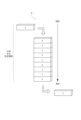
- FIG. 3 is a diagram illustrating standby processing according to the first embodiment.
- FIG. 4 is a diagram showing the first number of times of receiving and the second number of times of receiving according to the first embodiment.
- information indicating whether the article F was received from the first conveyor line 10 or the second conveyor line 20 is used as information indicating which direction the article F was received from with respect to the revolving conveyor 50.
- Information (hereinafter referred to as “direction information”) indicating whether the object was transported from is stored in the storage unit 61.
- direction information when the direction information is "3", it indicates that the article was conveyed to the rotating conveyor 50 from the third direction. In other words, when the direction information is "3", it indicates that the article F has been conveyed from the first conveyor line 10 to the turning conveyor 50. For example, when the direction information is "4", it indicates that the article F was conveyed to the rotating conveyor 50 from the fourth direction. In other words, when the direction information is "4", it indicates that the article F has been conveyed from the second conveyor line 20 to the turning conveyor 50.
- the control unit 62 determines the number of times the revolving conveyor 50 received the article F from the first conveyor line 10 (hereinafter referred to as "the number of times"
- the number of times the rotating conveyor 50 has received the article F from the second conveyor line 20 (hereinafter referred to as the "second receiving number") C2 are calculated.
- 3 and 4 illustrate a case where the predetermined number of times N is "10". Note that the predetermined number of times N may be changeable.
- the control unit 62 stores the direction information of the received article F as the performance data D in the storage unit 61. Therefore, in the example shown in FIG. 3, when new direction information is added to the performance data D for the most recent predetermined number of times N, the oldest direction information is deleted.
- the first receiving number C1 and the second receiving number C2 are not the number of times out of the most recent predetermined number N, but the times when the revolving conveyor 50 received the article F during the past period (predetermined period) by a predetermined time from the current time. It may also be the number of times received. The setting of this predetermined period may be changeable.
- the control unit 62 specifies the conveyor line with the larger number of receptions out of the first number of receptions C1 and the second number of receptions C2, and sets the state corresponding to the conveyor line with the larger number of receptions, that is, the state corresponding to the conveyor line with the larger number of receptions, that is, the state
- the revolving conveyor 50 is placed on standby in a state where it can receive the article F from the conveyor line that has been used more frequently. For example, when the first conveyor line 10 receives a large number of times, the control unit 62 causes the rotating conveyor 50 to stand by in the first state, and when the second conveyor line 20 receives a large number of times, the control unit 62 causes the rotating conveyor 50 to wait in the second state. Wait in a state.
- FIG. 4 illustrates the first number of receptions C1 and the second number of receptions C2 determined from the performance data D shown in FIG. 3.
- the first number of receptions C1 is seven times
- the second number of receptions C2 is three times. Therefore, in the examples shown in FIGS. 3 and 4, since the first receiving number C1 is greater than the second receiving number C2, the control unit 62 controls the number of receiving times C1 of the first conveyor line 10 and the second conveyor line 20.
- the first conveyor line 10 that has the largest number is identified.
- the control unit 62 causes the revolving conveyor 50 to stand by in a state where it can receive the article F from the first conveyor line 10, that is, in a first state.
- control unit 62 identifies the third direction among the plurality of directions (for example, the third direction and the fourth direction) in which the articles F flow to the rotating conveyor 50, which is the direction in which the articles are received more often, The orientation of the revolving conveyor 50 is switched and put on standby so that the article F can be received from the third direction.
- FIG. 5 is a flowchart of standby processing in the conveyor system control method according to the first embodiment.
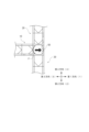
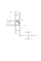
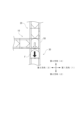
- 6 and 7 are diagrams showing operating states of the turning conveyor 50 in the conveyor system 1.
- the revolving conveyor 50 waits the article F (step S101)
- the revolving conveyor 50 passes the article F to the third conveyor line 30.
- the control unit 62 causes the rotating conveyor 50 to rotate around the vertical axis (FIG. 6B).
- the control unit 62 causes the third conveyor line 30 to convey the article F (FIG. 7A).
- the control unit 62 causes the third conveyor line 30 to convey the article F without rotating the rotating conveyor 50. That is, as shown in FIG. 7A, since the fourth direction 4, which is the direction of the second conveyor line 20, and the second direction 2, which is the direction of the third conveyor line 30, are in a straight line, the turning conveyor 50 is Articles F received from the second conveyor line 20 can be conveyed to the third conveyor line 30 without turning.
- the control unit 62 identifies the conveyor line that conveyed the article F (step S102). For example, the control unit 62 identifies the conveyor line that conveyed the article F based on the detection result of the detection unit 40. As an example, the control unit 62 may determine that the first conveyor line 10 has conveyed the article F when the detection unit 40A detects the article F. Further, the control unit 62 may determine that the second conveyor line 20 has conveyed the article F when the detection unit 40B detects the article F. Note that identifying the conveyor line that conveyed the article F includes identifying the direction in which the article F has been conveyed.
- control unit 62 When the control unit 62 identifies the conveyor line that conveyed the article F, the control unit 62 causes the storage unit 61 to store information indicating whether the article F was received from the specified conveyor line in chronological order for each article as performance data D (step S103).
- the control unit 62 calculates the first number of receptions C1 of the first conveyor line 10 and the second number of receptions C2 of the second conveyor line 20 based on the performance data D stored in the storage unit 61 (step S104).
- the control unit 62 determines which one of the first number of receptions C1 and the second number of receptions C2 is greater within a preset predetermined number of times or a predetermined period of time (step S105).
- control unit 62 determines that the first number of receptions C1 is greater than the second number of receptions C2
- the control unit 62 rotates the turning conveyor 50 around the vertical axis from the state shown in FIG. 7A, and as shown in FIG. 7B.
- the turning conveyor 50 is placed on standby in the first state (step S106).
- the control unit 62 determines that the second number of receptions C2 is greater than the first number of receptions C1, it causes the turning conveyor 50 to wait in the second state (step S107).
- the revolving conveyor 50 receives the article F from either the first conveyor line 10 or the second conveyor line 20.
- the turning conveyor 50 is made to stand by in the first state or the second state based on performance data D indicating the performance.
- FIG. 8 is a diagram showing an example of a conveyor system 1A according to the second embodiment.
- the same components as those in the first embodiment described above are given the same reference numerals, and the description thereof will be omitted or simplified.
- the conveyor system 1A includes a first conveyor line 10, a second conveyor line 20, a third conveyor line 30, a detection section 40, a turning conveyor 50, and a controller 60A.
- the controller 60A includes a storage section 61 and a control section 62A.
- the control unit 62A is realized, for example, by a hardware processor such as a CPU executing a program (software). Further, a part or all of the control unit 62A may be realized by hardware such as an LSI, an ASIC, an FPGA, or a GPU, or may be realized by cooperation between software and hardware.
- the control unit 62A has the function of the control unit 62 of the first embodiment.
- the control unit 62A can execute the standby process of the first embodiment.
- the control unit 62A controls the first receiving number C1 and Regardless of the second receiving number C2, the revolving conveyor 50 is kept on standby in a state where it can receive the article F from the conveyor line that has continuously conveyed the article F for a predetermined number of times M or more.
- the standby process of the second embodiment is such that when the revolving conveyor 50 receives the article F consecutively for a prescribed number of times M or more, the article F is continuously conveyed for the prescribed number of times M or more.
- the revolving conveyor 50 is placed on standby in a state in which it receives the article F from the conveyor line that has been loaded, and other processing is the same as in the first embodiment.
- the predetermined number of times M may be changeable.
- FIG. 9 is a diagram illustrating standby processing according to the second embodiment.
- direction information is stored in the storage unit 61 as information indicating from which of the first conveyor line 10 and the second conveyor line 20 the article F was received.
- FIG. 9 a case is illustrated in which the prescribed number of times M is "4".
- the control unit 62A determines whether the revolving conveyor 50 has received the article F from either the first conveyor line 10 or the second conveyor line 20 a prescribed number of times M or more consecutively. In FIG. 9, it is shown that the revolving conveyor 50 has recently received the article F from the fourth direction (second conveyor line 20) four times in a row. Therefore, the control unit 62A causes the turning conveyor 50 to stand by in the second state, regardless of the magnitude relationship between the first number of receptions C1 and the second number of receptions C2.
- the control unit 62A controls the control unit 62A to It is determined that there is a high possibility that the article F will be received from the same conveyor line, and the revolving conveyor 50 is placed on standby in the second state.
- the control unit 62A performs the same standby process as in the first embodiment.
- the standby state of the rotating conveyor 50 is determined by comparing the first number of receptions C1 and the second number of receptions C2.
- FIG. 10 is a flowchart of standby processing in the conveyor system control method according to the second embodiment.
- the rotating conveyor 50 waiting in the first state or the second state receives the article F (step S201)
- the rotating conveyor 50 passes the article F to the third conveyor line 30.
- the control unit 62A identifies the conveyor line that conveyed the article F (step S202).
- the control unit 62A causes the storage unit 61 to store information indicating whether the article F has been received from the specified conveyor line in chronological order for each article F as performance data D (step S203).
- the control unit 62A determines whether the rotating conveyor 50 has received the article F from the first conveyor line 10 consecutively for a predetermined number of times M or more (step S204). In step S204, the control unit 62A refers to the performance data D for the consecutive predetermined number of times M (that is, the performance data D for the most recent predetermined number of times M), including the performance data D regarding the article F received this time, and It is determined whether the article F has been received from the first conveyor line 10.
- control unit 62A determines that the revolving conveyor 50 has received articles F continuously for a predetermined number of times or more from the first conveyor line 10
- the controller 62A rotates the revolving conveyor 50 around the vertical axis to maintain the revolving conveyor 50 in the first state. 50 is put on standby (step S205).
- control unit 62A determines in step S204 that the revolving conveyor 50 has not received the articles F continuously from the first conveyor line 10 for a predetermined number of times M or more, the control unit 62A receives the performance data D stored in the storage unit 61. Based on this, it is determined whether the rotating conveyor 50 has received the article F from the second conveyor line 20 consecutively for a predetermined number of times M or more (step S206). In step S206, the control unit 62A refers to the performance data D for the predetermined number of consecutive times M (that is, the performance data D for the most recent predetermined number M), including the performance data D regarding the article F received this time, and It is determined whether the article F has been received from the second conveyor line 20.
- control unit 62A determines that the revolving conveyor 50 has received articles F continuously from the second conveyor line 20 for a predetermined number of times M or more, the controller 62A causes the revolving conveyor 50 to wait in the second state (step S207).
- control unit 62A determines in step S206 that the rotating conveyor 50 has not received the articles F from the second conveyor line 20 consecutively for a predetermined number of times M or more, the control unit 62A receives the performance data D stored in the storage unit 61. Based on this, the first number of receptions C1 of the first conveyor line 10 and the second number of receptions C2 of the second conveyor line 20 are calculated (step S208). The control unit 62A determines which one of the first number of receptions C1 and the second number of receptions C2 is greater within a preset predetermined number of times or a predetermined period of time (step S209).
- control unit 62A determines that the first number of receptions C1 is greater than the second number of receptions C2
- the control unit 62A rotates the rotating conveyor 50 around the vertical axis and makes the rotating conveyor 50 wait in the first state (step S210 ).
- the control unit 62A determines that the second number of receptions C2 is greater than the first number of receptions C1, it causes the turning conveyor 50 to stand by in the second state (step S211).
- the revolving conveyor when articles F are continuously received from a certain conveyor line for a predetermined number of times or more, the revolving conveyor is placed on standby so that it can receive articles F from this conveyor line. Conveyance efficiency is further improved.
- the turning conveyor 50 may be kept on standby in either the first state or the second state. .
- the state in which the turning conveyor 50 is placed on standby may be set in advance. For example, when the first receiving number C1 and the second receiving number C2 are the same, the turning angle from the direction of the third conveyor line 30 is smaller among the first conveyor line 10 and the second conveyor line 20.
- the turning conveyor 50 may be placed on standby while facing the direction of the conveyor line. With this configuration, unnecessary turning movements can be suppressed.
- step S105 if the first number of receptions C1 and the second number of receptions C2 are the same, the control unit 62 may cause the turning conveyor 50 to wait in the second state. Moreover, in step S209, the control unit 62A may cause the turning conveyor 50 to wait in the second state if the first number of times of receiving C1 and the second number of receiving times C2 are the same.
- this embodiment includes the following configuration.
- a rotating conveyor (50) that can rotate around a vertical axis, receives the article (F) from the first conveyor line (10) or the second conveyor line (20), and delivers the article (F) to the third conveyor line (30).
- a controller (60) for switching to a second state Equipped with The controller (60) allows the revolving conveyor (50) to transfer the article (F) to the first conveyor line (10) and the second conveyor line (20) after the revolving conveyor (50) passes the article (F) to the third conveyor line (30). making the rotating conveyor (50) wait in a first state or a second state based on performance data (D) indicating from which of the sources the article (F) was received; conveyor system.
- the controller (60) determines the number of times the revolving conveyor (50) receives the article (F) from the first conveyor line (10) and the number of times the revolving conveyor (50) receives the article (F) from the second conveyor line (10) based on the performance data (D). 20) and the number of times the article (F) was received from Among them, the rotating conveyor (50) is placed on standby in a state corresponding to the specified conveyor line; The conveyor system according to configuration 1 above.
- the controller (60) selects a first one of the most recent predetermined times that the revolving conveyor (50) has received the article (F) or the number of times that the revolving conveyor (50) has received the article (F) within a predetermined period. Comparing the number of times the article (F) was received from the conveyor line (10) and the number of times the article (F) was received from the second conveyor line (20); The conveyor system according to configuration 2 above.
- the controller (60) is configured to transmit a predetermined number of times when the revolving conveyor (50) receives the article (F) from either the first conveyor line (10) or the second conveyor line (20) consecutively for a predetermined number of times or more.
- a first conveyor line where the revolving conveyor (50) has received the article (F) for a predetermined number of times or more, regardless of whether or not the revolving conveyor (50) has received the article (F) many times in a predetermined period. (10) or identifying the second conveyor line (20); The conveyor system according to configuration 3 above.
- the predetermined number of times can be changed, The conveyor system according to any one of configuration 3 or configuration 4 above.
- Settings can be changed for a specified period of time. The conveyor system according to any one of configuration 3 or configuration 4 above.
- the controller (60) includes a storage unit that stores performance data (D), and when the rotating conveyor (50) receives the article (F) from the first conveyor line (10) or the second conveyor line (20), , information indicating whether the article (F) was received from the first conveyor line (10) or the second conveyor line (20) is stored in the storage unit (61) in chronological order for each article (F) as performance data (D). ),
- the conveyor system according to any one of configurations 1 to 6 above.
Landscapes
- Engineering & Computer Science (AREA)
- Mechanical Engineering (AREA)
- Control Of Conveyors (AREA)
- Attitude Control For Articles On Conveyors (AREA)
- Branching, Merging, And Special Transfer Between Conveyors (AREA)
Abstract
Description
図1は、第1実施形態に係るコンベヤシステム1の一例を示す図である。図1に示すように、コンベヤシステム1は、被搬送物が格納された容器(以下、「物品F」という。)を搬送する。例えば、コンベヤシステム1は、物品Fをストッカに搬入したり、ストッカから物品Fを搬出して処理装置に搬送したりする。物品Fには、例えば、半導体製造装置又は液晶製造装置等で処理されるウェハを収容するFOUP(Front Opening Unified Pod)、又は半導体製造装置又は液晶製造装置等で用いられるレチクルを収容するレチクルポッドである。上記の処理装置は、例えば、ウェハに洗浄、イオン注入、熱処理、リソグラフィ、エッチング、成膜、及び平坦化等の各種プロセスの処理を施す装置が含まれる。
第2実施形態のコンベヤシステム1Aについて説明する。図8は、第2実施形態に係るコンベヤシステム1Aの一例を示す図である。図8において、上記した第1実施形態と同様の構成については同一の符号を付してその説明を省略又は簡略化する。
[構成1]
物品(F)を搬送する第1コンベヤライン(10)、第2コンベヤライン(20)、及び第3コンベヤライン(30)と、
鉛直軸まわりに旋回可能であり、第1コンベヤライン(10)又は第2コンベヤライン(20)から物品(F)を受け取り、第3コンベヤライン(30)に物品(F)を渡す旋回コンベヤ(50)と、
鉛直軸まわりに旋回コンベヤ(50)を旋回させて、第1コンベヤライン(10)から物品(F)を受け取り可能な第1状態と、第2コンベヤライン(20)から物品(F)を受け取り可能な第2状態とに切り替えるコントローラ(60)と、
を備え、
コントローラ(60)は、旋回コンベヤ(50)が第3コンベヤライン(30)に物品(F)を渡した後に、旋回コンベヤ(50)が第1コンベヤライン(10)及び第2コンベヤライン(20)のいずれから物品(F)を受け取ったかを示す実績データ(D)に基づいて、旋回コンベヤ(50)を第1状態又は第2状態で待機させる、
コンベヤシステム。
[構成2]
コントローラ(60)は、実績データ(D)に基づいて、旋回コンベヤ(50)が第1コンベヤライン(10)から物品(F)を受け取った回数と、旋回コンベヤ(50)が第2コンベヤライン(20)から物品(F)を受け取った回数とを比較し、第1コンベヤライン(10)及び第2コンベヤライン(20)のうち回数が多いコンベヤラインを特定し、第1状態及び第2状態のうち、特定したコンベヤラインに対応する状態で旋回コンベヤ(50)を待機させる、
上記構成1に記載のコンベヤシステム。
[構成3]
コントローラ(60)は、旋回コンベヤ(50)が物品(F)を受け取った直近の所定回数のうち、又は旋回コンベヤ(50)が所定期間中に物品(F)を受け取った回数のうち、第1コンベヤライン(10)から物品(F)を受け取った回数と、第2コンベヤライン(20)から物品(F)を受け取った回数とを比較する、
上記構成2に記載のコンベヤシステム。
[構成4]
コントローラ(60)は、第1コンベヤライン(10)及び第2コンベヤライン(20)のいずれか一方から規定回数以上連続して旋回コンベヤ(50)が物品(F)を受け取った場合に、所定回数又は所定期間において旋回コンベヤ(50)が物品(F)を受け取った回数が多いか否かに関わらず、規定回数以上連続して旋回コンベヤ(50)が物品(F)を受け取った第1コンベヤライン(10)又は第2コンベヤライン(20)を特定する、
上記構成3に記載のコンベヤシステム。
[構成5]
所定回数は、設定変更が可能である、
上記構成3又は上記構成4のいずれか1つに記載のコンベヤシステム。
[構成6]
所定期間は、設定変更が可能である、
上記構成3又は上記構成4のいずれか1つに記載のコンベヤシステム。
[構成7]
コントローラ(60)は、実績データ(D)を記憶する記憶部を備え、旋回コンベヤ(50)が第1コンベヤライン(10)又は第2コンベヤライン(20)から物品(F)を受け取った場合に、第1コンベヤライン(10)及び第2コンベヤライン(20)のいずれから物品(F)を受け取ったかを示す情報を、実績データ(D)として物品(F)ごとに時系列で記憶部(61)に記憶させる、
上記構成1から上記構成6のいずれか1つに記載のコンベヤシステム。
D・・・実績データ
1、1A・・・コンベヤシステム
10・・・第1コンベヤライン
20・・・第2コンベヤライン
30・・・第3コンベヤライン
40・・・検出部
50・・・旋回コンベヤ
60、60A・・・コントローラ
61・・・記憶部
Claims (8)
- 物品を搬送する第1コンベヤライン、第2コンベヤライン、及び第3コンベヤラインと、
鉛直軸まわりに旋回可能であり、前記第1コンベヤライン又は前記第2コンベヤラインから前記物品を受け取り、前記第3コンベヤラインに前記物品を渡す旋回コンベヤと、
鉛直軸まわりに前記旋回コンベヤを旋回させて、前記第1コンベヤラインから前記物品を受け取り可能な第1状態と、前記第2コンベヤラインから前記物品を受け取り可能な第2状態とに切り替えるコントローラと、
を備え、
前記コントローラは、前記旋回コンベヤが前記第3コンベヤラインに前記物品を渡した後に、前記旋回コンベヤが前記第1コンベヤライン及び前記第2コンベヤラインのいずれから前記物品を受け取ったかを示す実績データに基づいて、前記旋回コンベヤを前記第1状態又は前記第2状態で待機させる、
コンベヤシステム。 - 前記コントローラは、前記実績データに基づいて、前記旋回コンベヤが前記第1コンベヤラインから前記物品を受け取った回数と、前記旋回コンベヤが前記第2コンベヤラインから前記物品を受け取った回数とを比較し、前記第1コンベヤライン及び前記第2コンベヤラインのうち回数が多いコンベヤラインを特定し、前記第1状態及び前記第2状態のうち、特定した前記コンベヤラインに対応する状態で前記旋回コンベヤを待機させる、
請求項1に記載のコンベヤシステム。 - 前記コントローラは、前記旋回コンベヤが前記物品を受け取った直近の所定回数のうち、又は前記旋回コンベヤが所定期間中に前記物品を受け取った回数のうち、前記第1コンベヤラインから前記物品を受け取った回数と、前記第2コンベヤラインから前記物品を受け取った回数とを比較する、
請求項2に記載のコンベヤシステム。 - 前記コントローラは、前記第1コンベヤライン及び前記第2コンベヤラインのいずれか一方から規定回数以上連続して前記旋回コンベヤが前記物品を受け取った場合に、前記所定回数又は前記所定期間において前記旋回コンベヤが前記物品を受け取った回数が多いか否かに関わらず、前記規定回数以上連続して前記旋回コンベヤが前記物品を受け取った前記第1コンベヤライン又は前記第2コンベヤラインを特定する、
請求項3に記載のコンベヤシステム。 - 前記所定回数は、設定変更が可能である、
請求項3に記載のコンベヤシステム。 - 前記所定期間は、設定変更が可能である、
請求項3に記載のコンベヤシステム。 - 前記コントローラは、前記実績データを記憶する記憶部を備え、前記旋回コンベヤが前記第1コンベヤライン又は前記第2コンベヤラインから前記物品を受け取った場合に、前記第1コンベヤライン及び前記第2コンベヤラインのいずれから前記物品を受け取ったかを示す情報を、前記実績データとして前記物品ごとに時系列で前記記憶部に記憶させる、
請求項1に記載のコンベヤシステム。 - 物品を搬送する第1コンベヤライン、第2コンベヤライン、及び第3コンベヤラインと、鉛直軸まわりに旋回可能であり、前記第1コンベヤライン又は前記第2コンベヤラインから前記物品を受け取り、前記第3コンベヤラインに前記物品を渡す旋回コンベヤとを備えるコンベヤシステムの制御方法であって、
前記旋回コンベヤが前記第3コンベヤラインに前記物品を渡した後に、前記旋回コンベヤが前記第1コンベヤライン及び前記第2コンベヤラインのいずれから前記物品を受け取ったかを示す実績データに基づいて、前記旋回コンベヤを、前記第1コンベヤラインから前記物品を受け取り可能な第1状態、又は前記第2コンベヤラインから前記物品を受け取り可能な第2状態で待機させること、
を含む、コンベヤシステムの制御方法。
Priority Applications (2)
| Application Number | Priority Date | Filing Date | Title |
|---|---|---|---|
| CN202380049062.9A CN119546535A (zh) | 2022-07-04 | 2023-06-07 | 输送系统以及输送系统的控制方法 |
| JP2024531959A JP7772218B2 (ja) | 2022-07-04 | 2023-06-07 | コンベヤシステム及びコンベヤシステムの制御方法 |
Applications Claiming Priority (2)
| Application Number | Priority Date | Filing Date | Title |
|---|---|---|---|
| JP2022107880 | 2022-07-04 | ||
| JP2022-107880 | 2022-07-04 |
Publications (1)
| Publication Number | Publication Date |
|---|---|
| WO2024009669A1 true WO2024009669A1 (ja) | 2024-01-11 |
Family
ID=89453162
Family Applications (1)
| Application Number | Title | Priority Date | Filing Date |
|---|---|---|---|
| PCT/JP2023/021108 Ceased WO2024009669A1 (ja) | 2022-07-04 | 2023-06-07 | コンベヤシステム及びコンベヤシステムの制御方法 |
Country Status (4)
| Country | Link |
|---|---|
| JP (1) | JP7772218B2 (ja) |
| CN (1) | CN119546535A (ja) |
| TW (1) | TW202402643A (ja) |
| WO (1) | WO2024009669A1 (ja) |
Citations (3)
| Publication number | Priority date | Publication date | Assignee | Title |
|---|---|---|---|---|
| JPS5031669B1 (ja) * | 1967-12-15 | 1975-10-14 | ||
| JPH0614138U (ja) * | 1992-07-24 | 1994-02-22 | 新キャタピラー三菱株式会社 | 搬送コンベア方向転換装置 |
| JP2006192082A (ja) * | 2005-01-13 | 2006-07-27 | Newgin Corp | 遊技機製造ライン |
-
2023
- 2023-06-07 JP JP2024531959A patent/JP7772218B2/ja active Active
- 2023-06-07 WO PCT/JP2023/021108 patent/WO2024009669A1/ja not_active Ceased
- 2023-06-07 CN CN202380049062.9A patent/CN119546535A/zh active Pending
- 2023-06-28 TW TW112124006A patent/TW202402643A/zh unknown
Patent Citations (3)
| Publication number | Priority date | Publication date | Assignee | Title |
|---|---|---|---|---|
| JPS5031669B1 (ja) * | 1967-12-15 | 1975-10-14 | ||
| JPH0614138U (ja) * | 1992-07-24 | 1994-02-22 | 新キャタピラー三菱株式会社 | 搬送コンベア方向転換装置 |
| JP2006192082A (ja) * | 2005-01-13 | 2006-07-27 | Newgin Corp | 遊技機製造ライン |
Also Published As
| Publication number | Publication date |
|---|---|
| JPWO2024009669A1 (ja) | 2024-01-11 |
| JP7772218B2 (ja) | 2025-11-18 |
| TW202402643A (zh) | 2024-01-16 |
| CN119546535A (zh) | 2025-02-28 |
Similar Documents
| Publication | Publication Date | Title |
|---|---|---|
| JP4986784B2 (ja) | 処理システムの制御装置、処理システムの制御方法および制御プログラムを記憶した記憶媒体 | |
| JP4860907B2 (ja) | 処理ツール間で小ロットサイズの基板キャリヤを移送するシステムおよび方法 | |
| CN100426452C (zh) | 用于材料控制系统接口的方法和设备 | |
| TWI355572B (en) | Methods and apparatus for integrating large and sm | |
| JP2007217078A (ja) | 方向転換装置 | |
| TWI441277B (zh) | Vacuum processing devices and programs | |
| JP2009076504A (ja) | 処理システムの制御装置、処理システムの制御方法および制御プログラムを記憶した記憶媒体 | |
| US7778721B2 (en) | Small lot size lithography bays | |
| EP3875405A1 (en) | Conveyor system | |
| JP5223778B2 (ja) | 基板処理装置、基板処理方法及び記憶媒体 | |
| JP2007088286A5 (ja) | ||
| CN111801785A (zh) | 真空处理装置的运转方法 | |
| JPWO2015107955A1 (ja) | 基板処理方法および基板処理装置 | |
| WO2024009669A1 (ja) | コンベヤシステム及びコンベヤシステムの制御方法 | |
| JP6384613B2 (ja) | 搬送制御装置及び搬送制御システム | |
| JP6870941B2 (ja) | 搬送条件設定装置、基板処理装置、および搬送条件設定方法 | |
| JP4979412B2 (ja) | 基板処理装置のスケジュール作成方法及びそのプログラム | |
| JP4942359B2 (ja) | ワーク加工装置 | |
| JP6750510B2 (ja) | 搬送装置 | |
| JP5852787B2 (ja) | 基板処理装置および基板処理方法 | |
| JP5348290B2 (ja) | 基板処理装置、基板処理方法及び記憶媒体 | |
| JPH01217938A (ja) | ウエハキャリアの自動搬送スシテム | |
| JP2011020790A (ja) | 仕分け装置及び仕分け装置制御方法 | |
| JP5075835B2 (ja) | 半導体製造システム | |
| KR102571030B1 (ko) | 기판 처리 장치 및 기판 처리 방법 |
Legal Events
| Date | Code | Title | Description |
|---|---|---|---|
| 121 | Ep: the epo has been informed by wipo that ep was designated in this application |
Ref document number: 23835205 Country of ref document: EP Kind code of ref document: A1 |
|
| WWE | Wipo information: entry into national phase |
Ref document number: 2024531959 Country of ref document: JP |
|
| WWE | Wipo information: entry into national phase |
Ref document number: 202380049062.9 Country of ref document: CN |
|
| NENP | Non-entry into the national phase |
Ref country code: DE |
|
| WWP | Wipo information: published in national office |
Ref document number: 202380049062.9 Country of ref document: CN |
|
| 122 | Ep: pct application non-entry in european phase |
Ref document number: 23835205 Country of ref document: EP Kind code of ref document: A1 |