WO2023286214A1 - 媒体搬送装置 - Google Patents
媒体搬送装置 Download PDFInfo
- Publication number
- WO2023286214A1 WO2023286214A1 PCT/JP2021/026494 JP2021026494W WO2023286214A1 WO 2023286214 A1 WO2023286214 A1 WO 2023286214A1 JP 2021026494 W JP2021026494 W JP 2021026494W WO 2023286214 A1 WO2023286214 A1 WO 2023286214A1
- Authority
- WO
- WIPO (PCT)
- Prior art keywords
- medium
- guide
- roller
- separation roller
- feeding
- Prior art date
Links
- 238000000926 separation method Methods 0.000 claims abstract description 193
- 238000011144 upstream manufacturing Methods 0.000 claims abstract description 37
- 238000001514 detection method Methods 0.000 claims description 26
- 238000000034 method Methods 0.000 claims description 24
- 239000002609 medium Substances 0.000 description 483
- 238000010586 diagram Methods 0.000 description 45
- 238000003384 imaging method Methods 0.000 description 30
- 230000008569 process Effects 0.000 description 20
- 239000000123 paper Substances 0.000 description 14
- 238000003825 pressing Methods 0.000 description 12
- 230000007246 mechanism Effects 0.000 description 11
- 238000004891 communication Methods 0.000 description 9
- 230000003287 optical effect Effects 0.000 description 7
- 230000002093 peripheral effect Effects 0.000 description 7
- 230000006870 function Effects 0.000 description 4
- 230000010365 information processing Effects 0.000 description 4
- 230000001105 regulatory effect Effects 0.000 description 4
- 238000006243 chemical reaction Methods 0.000 description 3
- 230000000630 rising effect Effects 0.000 description 3
- 230000005856 abnormality Effects 0.000 description 2
- 230000006835 compression Effects 0.000 description 2
- 238000007906 compression Methods 0.000 description 2
- 238000004590 computer program Methods 0.000 description 2
- 239000013013 elastic material Substances 0.000 description 2
- 238000005401 electroluminescence Methods 0.000 description 2
- 239000012526 feed medium Substances 0.000 description 2
- 230000009467 reduction Effects 0.000 description 2
- 230000009471 action Effects 0.000 description 1
- 238000005452 bending Methods 0.000 description 1
- 230000000903 blocking effect Effects 0.000 description 1
- 230000008859 change Effects 0.000 description 1
- 238000004140 cleaning Methods 0.000 description 1
- 230000000295 complement effect Effects 0.000 description 1
- 230000008602 contraction Effects 0.000 description 1
- 238000002474 experimental method Methods 0.000 description 1
- 230000010354 integration Effects 0.000 description 1
- 239000004973 liquid crystal related substance Substances 0.000 description 1
- 230000007257 malfunction Effects 0.000 description 1
- 239000000463 material Substances 0.000 description 1
- 229910044991 metal oxide Inorganic materials 0.000 description 1
- 150000004706 metal oxides Chemical class 0.000 description 1
- 230000008520 organization Effects 0.000 description 1
- 239000004033 plastic Substances 0.000 description 1
- 238000005381 potential energy Methods 0.000 description 1
- 230000002265 prevention Effects 0.000 description 1
- 239000011347 resin Substances 0.000 description 1
- 229920005989 resin Polymers 0.000 description 1
- 239000004065 semiconductor Substances 0.000 description 1
- 230000003746 surface roughness Effects 0.000 description 1
Images


Classifications
-
- B—PERFORMING OPERATIONS; TRANSPORTING
- B65—CONVEYING; PACKING; STORING; HANDLING THIN OR FILAMENTARY MATERIAL
- B65H—HANDLING THIN OR FILAMENTARY MATERIAL, e.g. SHEETS, WEBS, CABLES
- B65H3/00—Separating articles from piles
- B65H3/46—Supplementary devices or measures to assist separation or prevent double feed
- B65H3/56—Elements, e.g. scrapers, fingers, needles, brushes, acting on separated article or on edge of the pile
-
- B—PERFORMING OPERATIONS; TRANSPORTING
- B65—CONVEYING; PACKING; STORING; HANDLING THIN OR FILAMENTARY MATERIAL
- B65H—HANDLING THIN OR FILAMENTARY MATERIAL, e.g. SHEETS, WEBS, CABLES
- B65H3/00—Separating articles from piles
- B65H3/66—Article guides or smoothers, e.g. movable in operation
Definitions
- the present disclosure relates to a media transport device, and more particularly to a media transport device having a feed roller and a separation roller.
- a large number of media are required to improve the work efficiency of the user.
- media There is a demand for media to be collectively placed on a table and fed.
- the weight of the media as a whole increases and the friction between the media increases.
- multi-feed of media may occur. For example, by arranging a guide in front of the nip portion so that many media do not enter the nip portion between the feed roller and the separation roller, it is possible to suppress the occurrence of double feeding of the media.
- the leading edge of the medium may enter the nip portion between the feeding roller and the separation roller when the medium with the leading edge curled is fed. may be obstructed by guides.
- a medium feeding device includes a plurality of regulating portions provided at intervals in the medium width direction, which is the direction crossing the medium feeding direction, on the upstream side of a nip position between a separation roller and a feeding roller. (See Patent Document 1).
- the regulating portion is in contact with the leading edge of the upper medium except at least the lowest medium in the medium bundle, and restricts the contact of the leading edge with the separating roller, regardless of the deformation of the separation roller.
- a sheet conveying/separating device has been disclosed in which a separating roller is made of an elastic material, and a conveying regulation guide is provided in the vicinity of the separating roller so as to protrude relatively due to deformation of the elastic material (see Patent Document 2). .
- a medium conveying device is required to feed the medium satisfactorily.
- the purpose of the medium conveying device is to enable good feeding of the medium.
- a medium conveying device includes a mounting table, a feeding roller that feeds a medium mounted on the mounting table, and arranged above the feeding roller so as to face the feeding roller.
- the separation roller is arranged at a first position for limiting the contact between the bottom surface of the medium placed on the mounting table and the feeding roller before the medium is fed, and the medium placed on the mounting table is separated from the medium when the medium is fed.
- a lower surface guide arranged at a second position that allows contact between the lower surface and the feeding roller;
- a first guide that limits contact between the leading end and the separation roller, and is disposed between the upstream end of the separation roller in the medium conveying direction and the center of the separation roller, and serves as a nip portion between the feed roller and the separation roller during medium feeding.
- a second guide for regulating the leading edge of the medium at a position separated upward by a predetermined distance from the .
- the medium conveying device can feed the medium satisfactorily.
- FIG. 4 is a diagram for explaining a transport path inside the medium transport device 100;
- FIG. 4 is a schematic diagram for explaining a feeding mechanism 121;
- FIG. 4 is a schematic diagram for explaining a feeding mechanism 121;
- FIG. 4 is a schematic diagram for explaining a first guide 125 and the like;
- FIG. 4 is a schematic diagram for explaining a first guide 125 and the like;
- FIG. 4 is a schematic diagram for explaining a second guide 126;
- FIG. 4 is a schematic diagram for explaining a second guide 126;
- FIG. 5 is a schematic diagram for explaining the inclination of the second guide 126;
- 1 is a block diagram showing a schematic configuration of a medium conveying device 100;
- FIG. 4 is a diagram for explaining a transport path inside the medium transport device 100;
- FIG. 4 is a schematic diagram for explaining a feeding mechanism 121;
- FIG. 4 is a schematic diagram for explaining a feeding mechanism 121;
- FIG. 4 is a schematic
- FIG. 2 is a diagram showing a schematic configuration of a storage device 140 and a processing circuit 150;
- FIG. 7 is a flow chart showing an example of the operation of medium reading processing; It is a schematic diagram for demonstrating other 2nd guides 226 grade
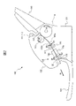
- FIG. 1 is a perspective view showing a medium conveying device 100 configured as an image scanner.
- the medium conveying device 100 conveys a medium, which is an original, and captures an image.
- the medium may be paper, thin paper, cardboard, card, passport, or the like.
- the card includes an ID-1 ID card defined by ISO (International Organization for Standardization)/IEC (International Electrotechnical Commission) 7810. Cards also include ID cards with embossments as specified in ISO/IEC 7811-1.
- the media transport device 100 may be a facsimile machine, a copier, a multifunction peripheral (MFP), or the like. Note that the medium to be conveyed may be an object to be printed instead of a document, and the medium conveying device 100 may be a printer or the like.
- the medium transport device 100 includes a lower housing 101, an upper housing 102, a mounting table 103, a discharge table 104, an operation device 105, a display device 106, and the like.
- arrow A1 indicates the medium transport direction.
- upstream refers to upstream in the medium transport direction A1
- downstream refers to downstream in the medium transport direction A1.
- an arrow A2 indicates the width direction orthogonal to the medium conveying direction.
- the upper housing 102 is arranged to cover the upper surface of the medium transporting device 100, and is engaged with the lower housing 101 by a hinge so that it can be opened and closed when the medium is clogged, when cleaning the inside of the medium transporting device 100, or the like.
- the mounting table 103 engages with the lower housing 101 and mounts a medium to be fed and transported.
- the mounting table 103 is inclined downward from the upstream side to the downstream side.
- the medium conveying device 100 can favorably convey the medium using the weight of the medium.
- the ejection table 104 engages with the upper housing 102 and places the ejected medium. Note that the discharge table 104 may be engaged with the lower housing 101 .
- the operation device 105 has an input device such as a button and an interface circuit that acquires signals from the input device, receives an input operation by the user, and outputs an operation signal according to the user's input operation.
- the display device 106 has a display including liquid crystal, organic EL (Electro-Luminescence), etc. and an interface circuit for outputting image data to the display, and displays the image data on the display.
- FIG. 2 is a diagram for explaining the transport path inside the medium transport device 100.
- FIG. 2 is a diagram for explaining the transport path inside the medium transport device 100.
- the transport path inside the medium transport device 100 includes a load sensor 111, a medium size sensor 112, a medium sensor 113, a feed roller 114, a separation roller 115, a first transport roller 116, a second transport roller 117, an imaging device 118, a 1 discharge roller 119, second discharge roller 120, and the like.
- each of the feed roller 114, the separation roller 115, the first conveying roller 116, the second conveying roller 117, the first discharge roller 119 and/or the second discharge roller 120 is not limited to one, and may be plural. good. In that case, the plurality of feeding rollers 114, separation rollers 115, first conveying rollers 116, second conveying rollers 117, first discharge rollers 119 and/or second discharge rollers 120 are spaced apart in the width direction A2. placed side by side.
- the upper surface of the lower housing 101 forms the lower guide 101a of the medium transport path
- the lower surface of the upper housing 102 forms the upper guide 102a of the medium transport path.
- the loading amount sensor 111 is a sensor for detecting the loading amount of media placed on the loading table 103 and is arranged upstream of the feed roller 114 and the separation roller 115 .
- the payload sensor 111 is an infrared proximity distance sensor that measures the distance to an object present at a facing position based on, for example, the time difference between irradiation and reflection of infrared rays.
- the payload sensor 111 has a light emitter and a light receiver provided on the upper housing 102 .
- the light emitter is an LED (Light Emitting Diode) or the like, and emits light (infrared rays) toward the mounting table 103 .
- the light receiver is a photodiode or the like, receives the light emitted by the light emitter and reflected by the mounting table 103 or the medium mounted on the mounting table 103, and outputs an electric signal corresponding to the received light. Generates and outputs a payload signal.
- the load signal indicates, for example, the time from when the light emitter emits light until when the light receiver receives the light. Based on the load signal, the medium transport device 100 detects the height of the medium placed on the placement table 103 as the load of the medium.
- the load sensor 111 may be a movement sensor (actuator).
- the movement amount sensor includes a contact member that contacts the top surface of the uppermost medium among the media mounted on the mounting table 103 and is movable upward by the medium that contacts the medium. Detect quantity.
- the load amount sensor 111 generates and outputs a load amount signal, which is an electric signal corresponding to the detected movement amount.
- the medium transport device 100 detects the height of the medium placed on the mounting table 103 as the load amount of the medium based on the load amount signal.
- the load amount sensor 111 may be a weight sensor for detecting the weight of the medium placed on the placement table 103 .
- the weight sensor has a pressure-sensitive sheet (conductive film sheet) arranged between the lower housing 101 and the mounting table 103, and the load amount sensor 111 responds to the pressure sensed by the pressure-sensitive sheet. It generates and outputs a load amount signal, which is an electrical signal.
- a load amount signal which is an electrical signal.
- the medium transport device 100 Based on the load signal, the medium transport device 100 detects the weight of the medium placed on the placement table 103 as the load of the medium.
- the medium size sensor 112 is a sensor for detecting the size of the medium, and is arranged upstream from the feed roller 114 and separation roller 115 .
- the medium size sensor 112 includes, for example, a plurality of optical sensors arranged side by side at intervals in the width direction A2 and detecting the medium at each arranged position.
- Each optical sensor includes a light emitter and a light receiver provided in one of lower housing 101 or upper housing 102 and the other housing of lower housing 101 or upper housing 102. , a light guide provided opposite the light emitter and the light receiver.
- the light emitter is an LED or the like, and emits light toward the light guide tube.
- the light receiver is a photodiode or the like, and receives light emitted by the light emitter and guided by the light guide tube.
- the medium size sensor 112 generates and outputs a medium size signal indicating whether or not a medium exists at a position facing each light emitter and light receiver based on the intensity of light received by each light receiver.
- a reflecting member such as a mirror may be used instead of the light guide tube. Also, the light emitter and the light receiver may be provided facing each other across the medium transport path.
- the medium size sensors 112 are arranged side by side at intervals in the width direction A2, and measure the distance to an object existing at the opposite position based on the time difference between irradiation and reflection of the infrared rays at each arranged position.
- a proximity sensor may also be used.
- the medium size sensor 112 has a light emitter and a light receiver provided on the upper housing 102 .
- the light emitter is an LED or the like, and emits light (infrared rays) toward the mounting table 103 .
- the light receiver is a photodiode or the like, and receives light emitted by the light emitter and reflected by the mounting table 103 or the medium mounted on the mounting table 103 .
- the medium size sensor 112 determines whether or not a medium exists at a position facing each light emitter and light receiver based on the time from when each light emitter emits light until each light receiver receives light. It generates and outputs a medium size signal to indicate.
- the medium size sensors 112 are arranged side by side at intervals in the width direction A2, and at each arranged position, a predetermined current flows when the medium is in contact or when the medium is not in contact.
- a contact detection sensor may be used.
- the medium size sensor 112 generates and outputs a medium size signal indicating whether or not a medium exists at a position facing each contact detection sensor depending on whether or not the medium is in contact with each contact detection sensor.
- the medium size sensor 112 may have an imaging sensor equipped with two-dimensionally arranged CMOS (Complementary Metal Oxide Semiconductor) or CCD (Charge Coupled Device) imaging elements.
- the medium size sensor 112 is arranged so as to be able to capture an image of the entire medium mounted on the mounting table 103 .
- the medium size sensor 112 further includes a lens that forms an image on the image sensor, and an A/D converter that amplifies the electrical signal output from the image sensor and performs analog/digital (A/D) conversion. .
- the medium size sensor 112 captures an image of the medium mounted on the mounting table 103, generates an image signal, and outputs the image signal as a medium size signal.
- the medium sensor 113 is arranged upstream from the feed roller 114 and the separation roller 115 .
- the medium sensor 113 has a contact detection sensor and detects whether or not a medium is mounted on the mounting table 103 .
- the medium sensor 113 generates and outputs a medium signal whose signal value changes depending on whether or not the medium is mounted on the mounting table 103 .
- the medium sensor 113 is not limited to a contact detection sensor, and any other sensor capable of detecting the presence or absence of a medium, such as a light detection sensor, may be used as the medium sensor 113 .
- the feeding roller 114 is provided in the lower housing 101, and separates and feeds the medium placed on the placing table 103 in order from the bottom.
- the separation roller 115 is a so-called brake roller or retard roller, which is arranged in the upper housing 102, i.e., above the feeding roller 114, facing the feeding roller 114, and rotates in the direction opposite to the medium feeding direction. .
- a first conveying roller 116 and a second conveying roller 117 are arranged on the downstream side of the feeding roller 114 so as to face each other, and convey the medium fed by the feeding roller 114 and the separation roller 115 to the imaging device 118 . do.
- the first transport rollers 116 are provided in the lower housing 101
- the second transport rollers 117 are provided in the upper housing 102 above the first transport rollers 116 .
- the imaging device 118 is arranged downstream from the first transport roller 116 and the second transport roller 117 and captures an image of the medium transported by the first transport roller 116 and the second transport roller 117 .
- the image pickup device 118 includes a first image pickup device 118a and a second image pickup device 118b arranged to face each other across the medium transport path.
- the first imaging device 118a has a linear optical system type CIS (Contact Image Sensor) line sensor having CMOS imaging elements linearly arranged in the main scanning direction. Also, the first imaging device 118a has a lens that forms an image on the imaging device, and an A/D converter that amplifies an electrical signal output from the imaging device and performs analog/digital (A/D) conversion.
- the first imaging device 118a captures an image of the surface of the medium being conveyed, generates an input image, and outputs the input image, under the control of a processing circuit, which will be described later.
- the second imaging device 118b has a linear optical system type CIS line sensor having CMOS imaging elements linearly arranged in the main scanning direction. Also, the second imaging device 118b has a lens that forms an image on the imaging device, and an A/D converter that amplifies an electrical signal output from the imaging device and performs analog/digital (A/D) conversion.
- the second image capturing device 118b captures an image of the back surface of the medium being conveyed, generates an input image, and outputs the input image, under the control of a processing circuit, which will be described later.
- the medium conveying device 100 may have only one of the first imaging device 118a and the second imaging device 118b and read only one side of the medium.
- a line sensor of the same-magnification optical system type CIS having the CMOS image pickup device instead of the line sensor of the same-magnification optical system type CIS having the CMOS image pickup device, a line sensor of the same-magnification optical system type CIS having the CCD image pickup device may be used. Also, a reduction optics type line sensor having a CMOS or CCD imaging device may be used.
- the first discharge roller 119 and the second discharge roller 120 are arranged on the downstream side of the imaging device 118 so as to face each other.
- the loaded medium is ejected onto the ejection table 104 .
- the first discharge rollers 119 are provided in the lower housing 101
- the second discharge rollers 120 are provided in the upper housing 102 above the first discharge rollers 119 .
- the medium placed on the mounting table 103 is moved in the medium transport direction A1 between the lower guide 101a and the upper guide 102a by rotating the feed roller 114 in the direction of the arrow A3 in FIG. 2, that is, the medium feed direction. transported towards.
- the medium conveying device 100 has, as feeding modes, a separation mode in which the medium is separated and fed, and a non-separation mode in which the medium is fed without being separated.
- the feeding mode is set by the user using the operation device 105 or the information processing device that communicates with the medium conveying device 100 .
- the separation roller 115 rotates in the direction of the arrow A4, that is, in the direction opposite to the medium feeding direction, during medium feeding.
- the medium is fed between the first transport roller 116 and the second transport roller 117 while being guided by the lower guide 101a and the upper guide 102a.
- the medium is fed between the first imaging device 118a and the second imaging device 118b by rotating the first transport roller 116 and the second transport roller 117 in the directions of arrows A5 and A6, respectively.
- the medium read by the imaging device 118 is ejected onto the ejection table 104 by rotating the first ejection roller 119 and the second ejection roller 120 in the directions of arrows A7 and A8, respectively.
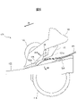
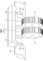
- FIG. 3 and 4 are schematic diagrams for explaining the feeding mechanism 121 of the medium conveying device 100.
- FIG. 3 is a schematic diagram of the feeding mechanism 121 viewed from the upstream side
- FIG. 4 is a schematic diagram of the feeding mechanism 121 viewed from the side (from the width direction A2).
- the medium conveying device 100 includes, as a feeding mechanism 121, a feeding roller 114 and a separation roller 115, as well as a guide member 122, a separation roller cover 123, a bottom surface guide 124, and a first guide. 125, a second guide 126, and the like.
- the medium conveying device 100 has two feed rollers 114 and two separation rollers 115 .
- the guide member 122 is a plate-like member, is provided on the upper surface of the lower housing 101 so as to form a medium transport surface 122a, and forms part of the lower guide 101a.
- the guide member 122 has an opening in the center in the width direction A2 orthogonal to the medium conveying direction, and the feeding roller 114 is arranged in the opening.
- the separation roller cover 123 is an example of a support section, and covers and supports the separation roller 115 .
- the separation roller cover 123 is attached to the upper housing 102 via an elastic member (not shown) such as a spring or rubber, and is biased downward by the elastic member. As a result, the separation roller cover 123 applies an urging force to the separation roller 115 so that the separation roller 115 presses the feeding roller 114 .
- the lower surface guide 124 is a set guide for setting the medium.
- the lower surface guide 124 is arranged at a position overlapping the feeding roller 114 and the separation roller 115 when viewed in the width direction A2, that is, at a position overlapping the feeding roller 114 and the separation roller 115 in the medium conveying direction A1.
- the lower surface guide 124 is provided on the lower housing 101 so as to be able to swing (rotate) downward (in the direction of arrow A9 in FIG. 4) according to a driving force from a motor (not shown).
- the lower surface guide 124 is arranged at a first position (arranged position shown in FIG.
- the lower surface guide 124 is formed of a member with high slidability (having a small frictional force against the medium) such as a plastic member.
- the lower guide 124 is formed of a member that has a smaller frictional force with the PPC paper than the frictional force between two PPC papers.
- the outer peripheral surface of the feed roller 114 is formed of a rubber member or the like having a large frictional force with respect to the medium so that the feed roller 114 can feed the medium satisfactorily. Therefore, the frictional force between the lowest medium among the media M1 placed on the platform 103 and the feed roller 114 is greater than the frictional force between the media M1.
- the mounting table 103 is inclined so that the downstream side faces downward so that the medium can be easily conveyed by its own weight. Therefore, if the medium transport device does not have a bottom surface guide, the leading edge of the medium placed on the upper side will precede the leading edge of the medium placed on the lowest side before the medium is fed ( downstream), and multi-feeding of media tends to occur during feeding of media.
- the medium transport device 100 can suppress the occurrence of double feeding of media.
- the first guide 125 is a flap and a stopper for preventing the medium from entering the nip portion between the feed roller 114 and the separation roller 115 before the medium is fed.
- the first guide 125 is arranged at a position facing the bottom surface guide 124 in the medium transport direction A1.
- the first guide 125 is provided in a later-described feeding arm housed in the separation roller cover 123 so as to be capable of swinging (rotating) downstream (in the direction of arrow A10 in FIG. 4).
- a member presses toward the upstream side (opposite direction of arrow A10).
- the first guide 125 engages with the bottom surface guide 124 arranged at the first position before the medium is fed, and limits the contact between the leading edge of the medium M1 placed on the placing table 103 and the separation roller 115 . That is, the first guide 125 prevents the medium from entering the nip portion between the feed roller 114 and the separation roller 115 before the medium is fed.
- the first guide 125 is provided to interlock with the feeding arm, and when the first guide 125 is engaged with the bottom guide 124, the feeding arm is supported by the first guide 125 and the bottom guide 124 to feed the feed arm. Downward movement of the arm is blocked. Therefore, in FIGS. 3 and 4, the feeding arm is housed inside the separation roller cover 123 .
- the first guide 125 is arranged upstream of the upstream end of the separation roller 115 and near the separation roller 115 in the medium conveyance direction A1 before the medium is fed. Therefore, the position (height) of the medium that abuts against the first guide 125 and stops before the medium is fed, and the position (height) of the medium that abuts against the separation roller 115 and stops immediately after the start of medium feeding. is small, and the magnitude of the potential energy generated by the difference in height is small. Therefore, immediately after the start of feeding the medium, the medium abuts against the separation roller 115 forcefully, the separation roller 115 is pushed up by the medium, and the reduction in the force for separating the medium is suppressed. Therefore, the medium conveying device 100 can suppress the occurrence of double feeding of media and can separate a plurality of media satisfactorily.
- the first guide 125 engages with the lower surface guide 124 arranged at the first position so as to be inclined with respect to the lower surface guide 124 . That is, the angle ⁇ 1 between the contact surface 125a of the first guide 125 that contacts the leading edge of the medium M1 and the support surface 124a of the lower surface guide 124 is set to be larger than 0° and smaller than 90°. In particular, the angle ⁇ 1 is set to be greater than 45° and less than 90°.
- the leading edge of the lower media is arranged downstream before the media are fed. This makes it easier for the medium to enter the nip portion between the feed roller 114 and the separation roller 115 . Therefore, the medium conveying device 100 can smoothly feed the medium at the start of medium feeding, and can reduce the time required for medium feeding.
- a plurality of sets of the first guides 125 and the lower surface guides 124 are arranged side by side at intervals in the width direction A2 perpendicular to the medium transport direction. They are arranged at approximately the same position in the direction A1. Also, each set of the first guide 125 and the lower surface guide 124 is arranged with an interval equal to or less than the minimum medium size width supported by the medium transport device 100 (for example, the length of A8 size in the lateral direction) in the width direction A2. be.
- the minimum medium size width supported by the medium transport device 100 for example, the length of A8 size in the lateral direction
- each set of the first guide 125 and the bottom guide 124 may be spaced apart in the width direction A2 larger than the minimum media size width supported by the media transport device 100 .
- the second guide 126 has a contact surface 126a that contacts the leading edge of the medium to be fed.
- the second guide 126 is provided on the separation roller cover 123 so as to protrude from the separation roller cover 123 above the nip portion between the feeding roller 114 and the separation roller 115 .
- the second guide 126 is arranged between the upstream end of the separation roller 115 in the medium conveyance direction A1 and the center O of the separation roller 115 in the medium conveyance direction A1.
- the second guide 126 is arranged outside the first guide 125 and near the separation roller 115 in the width direction A2 perpendicular to the medium conveying direction.
- the inner end of the second guide 126 is arranged within 30 mm from the outer end of the separation roller 115 in the width direction A2.
- the second guide 126 can regulate the central portion of the medium in the width direction A2, and can appropriately stop the medium.
- the second guide 126 can favorably regulate the leading edge of the media when a plurality of small-sized media are collectively placed on the placement table 103 and fed.
- the first guide 125 and/or the second guide 126 may be arranged between the two separation rollers 115 in the width direction A2.
- the second guide 126 is formed on the contact surface 126a so that the coefficient of friction of the first region 126b above the predetermined position is greater than the coefficient of friction of the second region 126c below the predetermined position. That is, the second guide 126 is formed such that the first region 126b and the second region 126c have different surface roughness or have different member friction resistances.
- the predetermined position is set, for example, at the center position between the upper end position and the lower end position of the contact surface 126a. Note that the predetermined position may be set at any position within the contact surface 126a.
- the coefficient of friction of the first region 126b is set to 0.5 or more, for example. For example, an uneven shape is formed in the first region 126b.
- a rubber member may be attached to the first region 126b.
- the coefficient of friction of the second region 126c is set to, for example, less than 0.5 (for example, approximately 0.3).
- the second region 126c is made of, for example, a resin material.
- the second guide 126 makes it easier for the leading end of the medium to be caught in the upper region of the contact surface 126a, and appropriately prevents the medium from entering the downstream side.
- the second guide 126 allows the leading edge of the medium to drop smoothly in the region below the contact surface 126a, and allows the medium to be smoothly guided to the nip portion between the feed roller 114 and the separation roller 115 by the pressure roller, which will be described later. .
- the second guides 126 are arranged side by side at intervals in the width direction A2 orthogonal to the medium conveying direction, and each of the second guides 126 is positioned substantially at the same position in the medium conveying direction A1. placed in Further, the second guides 126 are arranged at intervals equal to or less than the minimum medium size width supported by the medium transport device 100 plus a margin (for example, 40 mm) in the width direction A2.
- a margin for example, 40 mm
- the medium conveying device 100 can prevent the leading edge of the medium from being arranged at an angle, and can prevent the skew of the medium from occurring.
- FIG. 5 is a schematic diagram for explaining the lower surface guide 124 and the first guide 125 during medium feeding.
- FIG. 5 is a schematic side view of the feeding mechanism 121 during medium feeding.
- the feeding mechanism 121 further includes a feeding arm 127.
- the feeding arm 127 is housed inside the separation roller cover 123 so as to be vertically movable with respect to the separation roller cover 123 .
- the feeding arm 127 is attached inside the separation roller cover 123 via an elastic member (not shown) such as a spring or rubber, and is biased downward against the separation roller cover 123 by the elastic member.
- the feeding arm 127 is provided with a pressing roller 127a.
- the pressing roller 127a faces the feed roller 114 and is arranged upstream of the nip portion between the feed roller 114 and the separation roller 115 in the medium transport direction A1.
- the pressing roller 127a presses the medium fed by the feeding roller 114 from above toward the feeding roller 114 side.
- the pressing roller 127 a sandwiches the medium with the feeding roller 114 and applies a conveying force to the medium fed by the feeding roller 114 .
- the medium conveying device 100 can feed the medium satisfactorily.
- the lower surface guide 124 swings downward (in the direction of arrow A9) from the conveying surface 122a of the guide member 122.
- the lower surface guide 124 is arranged at the second position (arrangement position shown in FIG. 5) that allows contact between the lower surface of the medium M1 placed on the mounting table 103 and the feeding roller 114 during medium feeding. It is separated from the lower surface of the medium M1 placed on the placing table 103 .
- the engagement between the first guide 125 and the lower surface guide 124 is released.
- the first guide 125 is pushed by the leading edge of the medium M1 placed on the placing table 103 and swings downstream (in the direction of the arrow A10), and the medium M1 moves between the feed roller 114 and the separation roller. It becomes possible to enter the nip portion of 115 .
- the first guide 125 allows the medium M1 to enter the nip portion between the feed roller 114 and the separation roller 115 when the bottom guide 124 is arranged at the second position.
- the feeding arm 127 since the feeding arm 127 is biased downward by the elastic member, the feeding arm 127 is moved by releasing the engagement between the first guide 125 and the lower surface guide 124. , downward (toward the feeding roller 114).
- the amount of the medium M1 placed on the placement table 103 is sufficiently small. In this case, first, the feed roller 114 contacts the lowest medium among the media M1 placed on the mounting table 103, and then the pressing roller 127a is placed on the mounting table 103. It contacts the uppermost medium among the mediums M1.
- the pressing roller 127a is placed after the feeding roller 114 if the amount of the medium placed on the placing table 103 is less than a predetermined amount. It is provided so as to come into contact with the medium placed on the table 103 .
- the feeding roller 114 When the amount of the medium placed on the mounting table 103 is small, if the feeding roller 114 is started to rotate while the pressure roller 127a is pressing the medium, the leading edge of the medium tends to bend upward, which prevents the medium from jamming. Likely to happen.
- the medium conveying device 100 brings the feeding roller 114 into contact with the medium before the pressing roller 127a to start feeding the medium, thereby moving the leading edge of the medium upward. It is possible to suppress the occurrence of media jams due to bending.
- FIG. 6 is a schematic diagram for explaining the lower surface guide 124 and the first guide 125 when a large amount of media M2 are placed on the placing table 103.
- FIG. FIG. 6 is a schematic side view of the feeding mechanism 121 immediately after the start of medium feeding when a large amount of media M2 are placed on the mounting table 103. As shown in FIG.
- the bottom guide 124 is placed at the second position, the engagement between the first guide 125 and the bottom guide 124 is released, and the feeding arm 127 moves downward.
- the feed arm 127 is lowered before the lower surface guide 124 is lowered. Therefore, before the feeding roller 114 contacts the lowest medium among the media M2 placed on the mounting table 103, the pressure roller 127a is pressed against the medium M2 placed on the mounting table 103. It contacts the medium arranged on the uppermost side.
- the pressing roller 127a moves forward of the feeding roller 114 if the amount of media placed on the placing table 103 is equal to or greater than a predetermined amount. It is provided so as to come into contact with the medium mounted on the mounting table 103 .
- the feeding roller 114 can feed the medium satisfactorily by starting the rotation of the feeding roller 114 while the pressure roller 127a is pressing the medium. can.
- the elastic member applies a larger biasing force to the medium than when the amount of the medium is small.
- the elastic member is a compression spring
- the magnitude of the biasing force is a multiplication value obtained by multiplying the contraction amount of the spring by the spring constant.
- the medium transporting device 100 gives priority to the ability to feed the media, and feeds the media satisfactorily. It is possible to
- FIG. 7 is a schematic diagram for explaining the second guide 126 when a large amount of media M3 are mounted on the mounting table 103.
- FIG. FIG. 7 is a schematic side view of the feeding mechanism 121 during medium feeding when a large amount of media M3 are placed on the mounting table 103. As shown in FIG.
- the second guide 126 is designed to move the media. It abuts on the leading end of M3 to block entry of the medium M3 to the downstream side. As a result, the second guide 126 can prevent the separation roller 115 from being lifted (lifted) by the medium M3 and reducing the force for separating the medium.
- the second guide 126 regulates the leading edge of the medium at a position a predetermined distance D above the nip surface N, which is the extended surface of the nip portion between the feeding roller 114 and the separation roller 115, during the medium feeding. do. That is, the second guide 126 is arranged so as not to overlap the feeding roller 114 when viewed from the width direction A2 orthogonal to the medium conveying direction. Thereby, the second guide 126 contacts only the upper medium among the mediums M3 placed on the placing table 103 . Therefore, the second guide 126 allows the medium placed on the lower side to enter the nip portion between the feed roller 114 and the separation roller 115, while preventing the medium placed on the upper side from entering the downstream side. Restrict. Since only the media arranged on the lower side contact the separation roller 115, the second guide 126 can prevent the separation roller 115 from rising (floating) and reducing the force for separating the media.
- the ID card has high rigidity compared to paper, etc., and does not deform. Therefore, when the medium conveying device 100 attempts to separate a plurality of ID cards at the position of the second guide 126, the conveying load on the feeding roller 114 increases. Therefore, in order to separate a plurality of ID cards at the position of the second guide 126 , the medium conveying device 100 needs to increase the force with which the separation roller 115 presses the feeding roller 114 . However, if the force with which the separation roller 115 presses the feeding roller 114 is too large, it becomes difficult for the medium conveying device 100 to separate media such as paper.
- each ID card is appropriately separated at the nip portion between the feed roller 114 and the separation roller 115. Therefore, the medium conveying device 100 can handle the ID cards and It is possible to feed both sheets while separating them satisfactorily.
- the size of the ID card is small, and there is a high possibility that the side guide will not be set when the ID card is fed. Furthermore, since the frictional force between ID cards is small, when a plurality of ID cards are separated at the position of the second guide 126, the ID cards remaining at the position of the second guide 126 are tilted, causing the skew of the medium. more likely to. Since the second guide 126 is provided so that a plurality of ID cards can pass through, each ID card is properly separated at the nip portion between the feeding roller 114 and the separation roller 115, the medium conveying device 100 can prevent the medium from skewing. It is possible to suppress the occurrence of
- the predetermined distance D is preferably set to a length of 7 mm or less.
- the separation roller cover 123 has a guide surface 123a formed on the upstream side of the upstream end of the separation roller 115 in the medium conveying direction A1.
- An extended surface E obtained by extending the guide surface 123 a is arranged so as to pass through the central portion O of the separation roller 115 . That is, the guide surface 123a is formed at the same position as the center O of the separation roller 115 in the height direction.
- the feeding force required to cause it to increase is increased.
- the medium contacts a position higher than the central portion O on the outer peripheral surface of the separation roller 115 there is a possibility that the medium is not properly fed, causing a feeding abnormality.
- the medium transporting device 100 can limit the amount of media entering the position where the separation roller 115 contacts the separation roller cover 123 .
- the medium conveying device 100 can prevent the medium from contacting a position higher than the central portion O on the outer peripheral surface of the separation roller 115 . Therefore, it is possible to suppress the occurrence of medium feeding abnormality.
- the extended surface E obtained by extending the guide surface 123a may be arranged so as to be positioned below the central portion O of the separation roller 115 . That is, the guide surface 123a may be formed below the central portion O of the separation roller 115 in the height direction. By arranging the guide surface 123a at a position lower than the center O of the separation roller 115, the medium conveying device 100 can feed the medium with a sufficiently small feeding force.
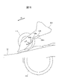
- FIG. 8 is a schematic diagram for explaining the second guide 126 when the medium M4 having a curled tip is placed on the placing table 103.
- FIG. 8 is a schematic side view of the feeding mechanism 121 during medium feeding when the medium M4 having a curled front end is placed on the placing table 103.
- the first guide 125 and the feeding arm 127 are omitted for better visibility.
- the separation roller 115 rotates in the direction A4 opposite to the medium feeding direction, and the feed roller 114 Push back any media that is not in contact with the
- the separation roller 115 moves to the feed roller 114. , and rotates in the medium feeding direction A9.
- the second guide 126 is arranged upstream of the upstream end of the separation roller 115 in the medium conveying direction A1
- the entry of the leading edge of the curled medium M4 into the nip portion between the feeding roller 114 and the separation roller 115 is It is blocked by the second guide 126 . Therefore, the medium M4 does not enter the nip portion between the feed roller 114 and the separation roller 115, and a medium jam occurs.
- the second guide 126 is arranged downstream of the upstream end of the separation roller 115 in the medium conveying direction A1.
- the leading edge of the curled medium M4 contacts the separation roller 115 without being blocked by the second guide 126, and is guided by the separation roller 115 rotating in the medium feeding direction A9. enter in between. Therefore, the medium conveying device 100 can suppress jamming of media with curled leading edges.
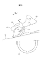
- FIG. 9 is a schematic diagram for explaining the inclination of the second guide 126.
- FIG. FIG. 9 is a schematic diagram of the second guide 126 viewed from the side.
- the first guide 125 and the feeding arm 127 are omitted for better visibility.
- the second guide 126 is arranged such that the contact surface 126 a that contacts the leading edge of the medium is inclined with respect to the nip surface N between the feeding roller 114 and the separation roller 115 . That is, the angle ⁇ 2 formed by the contact surface 126a of the second guide 126 and the nip surface N is set to be larger than 0° and smaller than 90°. In particular, the angle ⁇ 2 is set to be greater than 45° and less than 90°. As a result, of the media in contact with the contact surface 126a, the leading edge of the lower media is arranged on the downstream side. It becomes easier to enter the nip portion of the separation roller 115 . Therefore, the medium conveying device 100 can smoothly feed the medium at the start of medium feeding, and can reduce the time required for medium feeding.
- the separation roller 115 is pulled by the feeding roller 114 at the nip portion with the feeding roller 114 .
- the downstream end of the nip portion of the separation roller 115 swells, and the upstream end of the nip portion of the separation roller 115 dents accordingly. Therefore, as shown in FIG. 9, a recess 115a is formed in the upstream and lower portion of the outer peripheral surface of the separation roller 115.
- the abutment surface 126a of the second guide 126 is inclined with respect to the nip surface N so as to be arranged substantially parallel to the recess 115a. abut evenly on the As a result, the second guide 126 can evenly apply a load to the media in contact with each other and appropriately align the leading edges of the media. As a result, the medium conveying device 100 can feed the medium more satisfactorily.
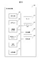
- FIG. 10 is a block diagram showing a schematic configuration of the medium conveying device 100. As shown in FIG.
- the medium transport device 100 further includes a motor 131, an interface device 132, a storage device 140, a processing circuit 150, etc., in addition to the configuration described above.
- the motor 131 has one or a plurality of motors, and operates the feed roller 114, the separation roller 115, the first conveying roller 116, the second conveying roller 117, the first discharge roller 119 and the first discharge roller 119 according to a control signal from the processing circuit 150. 2
- the discharge roller 120 is rotated to convey the medium.
- One of the first transport roller 116 and the second transport roller 117 may be a driven roller that rotates following the other roller.
- one of the first discharge roller 119 and the second discharge roller 120 may be a driven roller that rotates following the other roller.
- the motor 131 moves the lower surface guide 124 between the first position and the second position according to control signals from the processing circuit 150 .
- the interface device 132 has an interface circuit conforming to a serial bus such as USB, for example, and is electrically connected to an information processing device (for example, personal computer, personal digital assistant, etc.) (not shown) to receive an input image and various information. Send and receive.
- an information processing device for example, personal computer, personal digital assistant, etc.
- a communication unit having an antenna for transmitting and receiving wireless signals and a wireless communication interface device for transmitting and receiving signals through a wireless communication line according to a predetermined communication protocol may be used.
- the predetermined communication protocol is, for example, a wireless LAN (Local Area Network).
- the communication unit may have a wired communication interface device for transmitting and receiving signals through a wired communication line according to a communication protocol such as a wired LAN.
- the storage device 140 includes memory devices such as RAM (Random Access Memory) and ROM (Read Only Memory), fixed disk devices such as hard disks, or portable storage devices such as flexible disks and optical disks.
- the storage device 140 also stores computer programs, databases, tables, and the like used for various processes of the medium transport device 100 .
- the computer program may be installed in the storage device 140 from a computer-readable portable recording medium using a known setup program or the like.
- the portable recording medium is, for example, a CD-ROM (compact disc read only memory), a DVD-ROM (digital versatile disc read only memory), or the like.
- the processing circuit 150 operates based on a program stored in the storage device 140 in advance.
- the processing circuit is, for example, a CPU (Central Processing Unit).
- a DSP digital signal processor
- LSI large scale integration
- ASIC Application Specific Integrated Circuit
- FPGA Field-Programmable Gate Array
- the processing circuit 150 is connected to the operation device 105, the display device 106, the load amount sensor 111, the medium size sensor 112, the medium sensor 113, the imaging device 118, the motor 131, the interface device 132, the storage device 140, etc., and controls these units. Control. Based on the medium signal received from the medium sensor 113 , the processing circuit 150 performs drive control of the motor 131 , imaging control of the imaging device 118 , acquires an input image from the imaging device 118 , and outputs information via the interface device 132 . Send to processor.
- FIG. 11 is a diagram showing a schematic configuration of the storage device 140 and the processing circuit 150. As shown in FIG.
- the storage device 140 stores a control program 141, an image acquisition program 142, a detection program 143, and the like. Each of these programs is a functional module implemented by software running on a processor.
- the processing circuit 150 reads each program stored in the storage device 140 and operates according to each read program. Thereby, the processing circuit 150 functions as a control section 151 , an image acquisition section 152 and a detection section 153 .
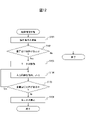
- FIG. 12 is a flow chart showing an example of the operation of the medium reading process of the medium conveying device 100.
- control unit 151 receives an instruction to read a medium from the operation device 105 or the interface device 132 when a user inputs an instruction to read the medium using the operation device 105 or the information processing device. (step S101).
- control unit 151 acquires a medium signal from the medium sensor 113, and determines whether or not a medium is placed on the placing table 103 based on the acquired medium signal (step S102). If no medium is placed on the placing table 103, the control unit 151 terminates the series of steps.
- the control section 151 drives the motor 131 to move the lower surface guide 124 from the first position to the second position. Further, the control unit 151 drives the motor 131 to rotate the feed roller 114, the separation roller 115, the first transport roller 116, the second transport roller 117, the first discharge roller 119 and/or the second discharge roller 120. to convey the medium (step S103).
- the image acquisition unit 152 causes the imaging device 118 to image the medium, acquires an input image from the imaging device 118, and transmits the acquired input image to the information processing device via the interface device 132, thereby outputting the image. (step S104).
- control unit 151 determines whether or not the medium remains on the mounting table 103 (step S105). When the medium remains on the mounting table 103, the control unit 151 returns the process to step S104 and repeats the processes of steps S104 and S105.
- control unit 151 controls the feeding roller 114, the separating roller 115, the first conveying roller 116, the second conveying roller 117, the first discharge roller 119 and/or the second discharge.
- Motor 131 is controlled to stop roller 120 .
- control unit 151 controls the motor 131 so as to move the lower surface guide 124 from the second position to the first position (step S106), and ends the series of steps.
- the medium transport device 100 has the first guide 125 that limits the contact between the leading edge of the medium and the separation roller 115 before feeding the medium.
- the medium conveying device 100 includes a second guide 126 arranged downstream of the upstream end of the separation roller 115 and regulating the leading edge of the medium at a predetermined distance above the nip portion between the feeding roller 114 and the separation roller 115 . have.
- the medium conveying device 100 guides only an appropriate amount of media out of the media restricted by the first guide 125 to the nip portion, and suppresses other media from pressing the separation roller 115 .
- the medium conveying device 100 can prevent the separating roller 115 from rising (floating) and reducing the force for separating the medium.
- the medium conveying device 100 can separate a plurality of media satisfactorily, and can suppress the occurrence of double feeding of media.
- the medium conveying device 100 can prevent the second guide 126 from preventing the medium with the curled leading edge from entering the nip portion between the feed roller 114 and the separation roller 115 . Therefore, the medium conveying device 100 can feed the medium satisfactorily.
- the medium conveying device 100 regulates the leading edge of the medium at a predetermined distance above the nip portion between the feed roller 114 and the separation roller 115 , so that regardless of the amount of the medium placed on the platform 103 , the medium can be transported. It is now possible to suppress the occurrence of double feeding and to feed media stably.
- the medium transport device 100 can feed various types of media such as normal paper, thin paper whose tip tends to curl, cards, thick paper, and passports.
- the medium transport device 100 can stably feed media regardless of the number or types of media to be fed. Therefore, the user does not need to change the settings of the medium transporting device 100 according to the number or type of media to be fed, and the medium transporting device 100 can improve user convenience. . Along with this, the medium transport device 100 can suppress the occurrence of setting errors by the user, and can suppress the occurrence of malfunctions due to setting errors. In addition, the medium conveying device 100 does not need to provide special parts for feeding a special type of medium or a large amount of media, and it is possible to suppress an increase in device cost. It has become possible.
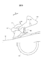
- FIGS. 13 and 14 are schematic diagrams for explaining the separation roller cover 223 and the second guide 226 in the medium conveying device according to another embodiment.
- FIG. 13 is a schematic diagram of the separation roller cover 223 viewed from the upstream side.
- FIG. 14 is a schematic diagram of the separation roller cover 223 viewed from the side.
- the display of the guide member 122 is omitted in order to improve visibility.
- the medium conveying device has a separation roller cover 223 and second guides 226 instead of the separation roller cover 123 and second guides 126 .
- the separation roller cover 223 and the second guide 226 have the same configurations as the separation roller cover 123 and the second guide 126.
- the second guide 226 has a fixed portion 226a and a moving portion 226b.
- the fixed portion 226 a is provided so as to be fixed to the separation roller cover 223 .
- the fixing portion 226a is provided above the nip surface N, which is an extension surface of the nip portion between the feeding roller 114 and the separation roller 115, by a predetermined distance D.
- the moving portion 226b is provided between the fixed portion 226a and the nip portion between the feed roller 114 and the separation roller 115 so as to be movable by the leading edge of the medium to be fed.
- the moving part 226b is provided at the lower end of the fixed part 226a so as to be able to swing (rotate) downstream (in the direction of arrow A11 in FIG. 14), and is moved upstream (rotatingly) by an elastic member (not shown) such as a torsion coil spring. (opposite direction of arrow A11).
- each medium is applied with a downstream force by the feed roller 114 and an upstream force by the separation roller 115.
- the pressing force applied to the moving portion 226b by the elastic member is smaller than the downstream force applied to the medium in contact with the feed roller 114 and is applied to the medium not in contact with the feed roller 114 toward the downstream side. set to be greater than the force.
- the second guide 226 can satisfactorily guide the media to be fed (including cards, etc.) to the nip portion between the feed roller 114 and the separation roller 115, while suppressing the occurrence of double feeding of the media.
- the medium conveying device can feed the medium satisfactorily even when the second guide 226 has the fixed portion 226a and the moving portion 226b.
- FIGS. 15 and 16 are schematic diagrams for explaining the separation roller cover 323 and the second guide 326 in the medium conveying device according to still another embodiment.
- FIG. 15 is a schematic diagram of the separation roller cover 323 viewed from the upstream side.
- FIG. 16 is a schematic diagram of the separation roller cover 323 viewed from the side.
- the display of the guide member 122 is omitted in order to improve visibility.
- 15 and 16 show the second guide 326 before medium feeding (initial state).
- the medium conveying device has a separation roller cover 323 and second guides 326 instead of the separation roller cover 123 and second guides 126 .
- the separation roller cover 323 and the second guide 326 have the same configurations as the separation roller cover 123 and the second guide 126.
- the second guide 326 has a shaft 326a, a contact portion 326b and an arm 326c.
- the second guide 326 has two contact portions 326b and two arms 326c.
- the shaft 326a is provided on the separation roller cover 323 so as to be rotatable around a rotation axis extending in the width direction A2, and is directed upstream (opposite direction of arrow A12) by an elastic member (not shown) such as a torsion coil spring. is pressed down.
- the abutment portion 326b has a first abutment surface that abuts against the leading edge of the medium being fed, and is provided on the shaft 326a so as to be rotatable (swingable) as the shaft 326a rotates.
- the first contact surface is arranged at the non-contact position (placement position shown in FIGS. 15 and 16) where it does not contact the leading edge of the medium.
- the contact portion 326b is arranged outside the first guide 125 and near the separation roller 115 in the width direction A2 orthogonal to the medium conveying direction. Each contact portion 326b is arranged at substantially the same position in the medium transport direction A1. Also, the contact portions 326b are arranged at intervals equal to or less than the minimum medium size width supported by the medium transport device 100 plus a margin in the width direction A2.
- the arm 326c has a second contact surface that contacts the upper surface of the medium being fed, and is provided on the shaft 326a so as to rotate the shaft 326a as the arm 326c moves (swings).
- the arm 326c is arranged outside the contact portion 326b in the width direction A2 orthogonal to the medium transport direction.
- Each arm 326c has a distance greater than the longitudinal length of an ID-1 ID card (85.6 mm) defined by ISO/IEC7810 or the longitudinal length of a folded passport (125 mm). are placed in an empty space.
- Each arm 326c is arranged at substantially the same position in the medium transport direction A1.
- FIGS. 17 and 18 are schematic diagrams for explaining the second guide 326 with the contact portion 326b set.
- FIG. 17 is a schematic diagram of the separation roller cover 323 viewed from the upstream side.
- FIG. 18 is a schematic diagram of the separation roller cover 323 viewed from the side.
- the display of the guide member 122 is omitted in order to improve visibility.
- the contact portion 326b set at the contact position is provided above the nip portion between the feed roller 114 and the separation roller 115 so as not to overlap the feed roller 114 when viewed from the width direction A2 orthogonal to the medium conveying direction. placed in The contact portion 326b set at the contact position is arranged between the upstream end of the separation roller 115 in the medium conveyance direction A1 and the central portion O of the separation roller 115 in the medium conveyance direction A1.
- the second guide 326 is provided so as to be movable by the medium when the height of the medium in contact with the separation roller 115 is equal to or higher than a predetermined height. Accordingly, when a medium group having a width longer than the distance between the two arms 326c and a height that contacts the arms 326c is placed on the mounting table 103, the second guide 326 can move the medium group. It abuts on the tip to prevent the media group from entering the downstream side. Therefore, the second guide 326 can prevent the separation roller 115 from rising (lifting) due to the medium group and reducing the force for separating the medium.
- the arms 326c do not contact the medium, so the contact portion 326b is moved to the non-contact position. placed in Therefore, the abutting portion 326b can feed the medium well without blocking the feeding of the thick medium such as an ID card or a passport.
- the medium conveying device can feed the medium satisfactorily even when the second guide 326 is provided so as to be movable according to the height of the medium.
- FIG. 19 is a schematic diagram for explaining the separation roller cover 423 and the second guide 426 in the medium conveying device according to still another embodiment.
- FIG. 19 is a schematic diagram of the separation roller cover 423 viewed from the side. In FIG. 19, the display of the guide member 122 is omitted in order to improve visibility.
- FIG. 19 shows the second guide 426 before medium feeding (initial state).
- the medium conveying device has a separation roller cover 423, a second guide 426 and a cam 427 instead of the separation roller cover 123 and the second guide 126.
- the separation roller cover 423 and the second guide 426 have the same configurations as the separation roller cover 123 and the second guide 126.
- the second guide 426 is provided on the separation roller cover 423 so as to be able to swing (rotate) upstream (in the direction of arrow A13 in FIG. 19), and is moved downstream by an elastic member (not shown) such as a torsion coil spring. side (opposite direction of arrow A13).
- an elastic member such as a torsion coil spring.
- the second guide 426 is arranged at the non-contact position (placement position shown in FIG. 19) where it does not come into contact with the leading edge of the medium.
- the cam 427 is provided on the separation roller cover 423 so as to be able to swing (rotate) in the direction of arrow A14 in FIG. Before the medium is fed (initial state), the cam 427 is arranged at a position separated from the second guide 426 .
- FIG. 20 is a schematic diagram for explaining the second guide 426 in the set state.
- FIG. 20 is a schematic diagram of the separation roller cover 423 viewed from the side.
- the display of the guide member 122 is omitted in order to improve visibility.
- the second guide 426 is provided above the nip portion between the feed roller 114 and the separation roller 115, and is arranged so as not to overlap the feed roller 114 when viewed in the width direction A2 orthogonal to the medium conveying direction. be done.
- the second guide 426 set at the contact position is arranged between the upstream end of the separation roller 115 in the medium conveyance direction A1 and the center O of the separation roller 115 in the medium conveyance direction A1.
- the second guide 426 abuts against the leading edge of the medium to prevent the medium from entering the downstream side when arranged at the abutment position, and prevents the medium from being fed when the second guide 426 is arranged at the non-abutment position. To feed a medium without interrupting the feeding.
- FIG. 21 is a flow chart showing an example of the operation of the medium reading process of the medium conveying device having the second guide 426 and cam 427.
- the operation flow described below is executed mainly by the processing circuit 150 in cooperation with each element of the medium conveying device 100 based on a program stored in advance in the storage device 140 .
- the flowchart shown in FIG. 21 is executed instead of the flowchart shown in FIG.
- the processing of steps S201 to S203 and S211 to S213 of the flowchart shown in FIG. 21 is the same as the processing of steps S101 to S103 and S104 to S106 of the flowchart shown in FIG. Only the processing of steps S204 to S210 will be described below.
- the second guide 426 is placed at the non-contact position before the flowchart shown in FIG. 21 is executed, that is, before the medium is fed.
- control unit 151 determines whether the feeding mode is set to the separation mode or the non-separation mode (step S204).
- the control unit 151 drives the motor 131 to place the second guide 426 at the non-contact position (step S205), and the process proceeds to step S211. .
- the control section 151 retracts the second guide 426 when the medium conveying device 100 operates in the non-separation mode.
- the control unit 151 can retract the second guide 426 to feed the booklet satisfactorily. Note that when the second guide 426 has already been arranged at the non-contact position, the control unit 151 moves the process to step S211 without executing any particular process.
- the detection unit 153 receives the load amount signal from the load amount sensor 111, and determines the size of the medium placed on the mounting table 103 based on the received load amount signal.
- a loading amount is detected (step S206).
- the medium transport device 100 stores in the storage device 140 in advance a table showing the relationship between the signal value of the load amount signal and the load amount (height or weight) of the medium.
- the detection unit 153 refers to the table and specifies the loading amount corresponding to the signal value of the received loading amount signal as the loading amount of the media placed on the mounting table 103 .
- control unit 151 determines whether or not the detected load amount is equal to or greater than a predetermined amount (step S207).
- the predetermined amount is set in advance to a loading amount that requires regulation of the media by the second guide 426 .
- control unit 151 drives the motor 131 to place the second guide 426 at the non-contact position (step S205), and the process proceeds to step S211. Note that when the second guide 426 has already been arranged at the non-contact position, the control unit 151 moves the process to step S211 without executing any particular process.
- the detection unit 153 receives a medium size signal from the medium size sensor 112 and detects the size of the medium placed on the placing table 103 based on the received medium size signal. (step S208). If the medium size signal indicates whether or not a medium exists at a position facing each light emitter and light receiver, the detection unit 153 determines which medium exists in the set of light emitters and light receivers at positions facing each other. The arrangement interval between the two outermost sets is detected as the size in the width direction A2 of the medium. When the medium size signal indicates whether or not the medium exists at the position facing each contact detection sensor, the detection unit 153 detects the two outermost sensors among the sensors at which the medium exists at the facing position.
- the detection unit 153 uses a known image processing technique to detect the size of the medium in the medium transport direction A1 and/or the width direction A2 from the image signal.
- the control unit 151 determines whether or not the size of the detected medium is equal to or larger than a predetermined size (step S209).
- the predetermined size is, for example, the longitudinal length (85.6 mm) of an ID-1 ID card defined by ISO/IEC7810, or the longitudinal length (125 mm) of a folded passport plus a margin. set to the same size.
- the control unit 151 determines whether the longer size of the detected sizes of the medium is equal to or larger than a predetermined size. determine whether In this case, the control unit 151 may determine whether the shorter size of the detected medium sizes is equal to or greater than a predetermined size.
- control unit 151 drives the motor 131 to place the second guide 426 at the non-contact position (step S205), and the process proceeds to step S211. Note that when the second guide 426 has already been arranged at the non-contact position, the control unit 151 moves the process to step S211 without executing any particular process.
- control unit 151 drives the motor 131 to place the second guide 426 at the contact position (step S210). Note that when the second guide 426 has already been arranged at the contact position, the control unit 151 moves the process to step S211 without executing any particular process.
- control unit 151 moves the second guide 426 according to the load amount of media placed on the placement table 103 .
- the control unit 151 can set the second guide 426 when the medium stacking amount is large, and retract the second guide 426 when the medium stacking amount is small. Therefore, the control unit 151 satisfactorily separates the media when the stacking amount of the media is large, and prevents jamming of the media with curled ends by the second guide 426 when the stacking amount of the media is small. can be suppressed.
- control unit 151 moves the second guide 426 according to the size of the medium placed on the placing table 103 .
- the control unit 151 retracts the second guide 426 when a medium having a small size and thickness such as a passport or a card is fed, and when general paper or the like is fed.
- the second guide 426 can be set. Therefore, the control unit 151 can satisfactorily feed a small and thick medium such as a passport or a card, and satisfactorily separate ordinary paper and the like.
- control unit 151 causes the second guide 426 to abut when at least one of the load amount is equal to or greater than a predetermined amount and the size of the media is equal to or greater than a predetermined size. can be placed in position. Also, the process of step S204 may be omitted. Further, the processing of steps S206-S207 and/or steps S208-S209 may be omitted.
- the medium conveying device can feed the medium satisfactorily even when the second guide 426 is movable under the control of the control unit 151 .
- FIG. 22 is a diagram showing a schematic configuration of a processing circuit 550 in a medium conveying device according to still another embodiment.
- the processing circuit 550 is used in place of the processing circuit 150 of the medium transport device 100, and performs medium reading processing and the like instead of the processing circuit 150.
- FIG. The processing circuit 550 has a control circuit 551, an image acquisition circuit 552, a detection circuit 553, and the like. Each of these units may be composed of an independent integrated circuit, microprocessor, firmware, or the like.
- the control circuit 551 is an example of a control section and has the same function as the control section 151.
- the control circuit 551 receives an operation signal from the operation device 105 or the interface device 132 , a medium signal from the medium sensor 113 , and detection results of the loaded amount and size of the medium from the detection circuit 553 .
- the control circuit 551 controls the motor 131 based on the received information.
- the image acquisition circuit 552 is an example of an image acquisition section and has the same function as the image acquisition section 152.
- the image acquisition circuit 552 acquires an input image from the imaging device 118 and outputs it to the interface device 132 .
- the detection circuit 553 is an example of a detection section and has the same function as the detection section 153.
- the detection circuit 553 receives the load signal from the load sensor 111 and the medium size signal from the medium size sensor 112 .
- the detection circuit 553 detects the loaded amount and size of the medium based on each received signal, and outputs the detection result to the control circuit 551 .
- the medium conveying device can feed the medium satisfactorily even when the processing circuit 550 is used.
Landscapes
- Engineering & Computer Science (AREA)
- Mechanical Engineering (AREA)
- Sheets, Magazines, And Separation Thereof (AREA)
Abstract
媒体を良好に給送することが可能な媒体搬送装置を提供する。媒体搬送装置は、載置台と、載置台に載置された媒体を給送する給送ローラと、給送ローラの上方に、給送ローラと対向して配置される分離ローラと、媒体給送前に、載置台に載置された媒体の下面と給送ローラの接触を制限する第1位置に配置され、媒体給送時に、載置台に載置された媒体の下面と給送ローラの接触を許容する第2位置に配置される下面ガイドと、媒体給送前に、第1位置に配置された下面ガイドと係合し、載置台に載置された媒体の先端と分離ローラの接触を制限する第1ガイドと、分離ローラの媒体搬送方向の上流端と分離ローラの中心部との間に配置され、媒体給送時に、給送ローラと分離ローラのニップ部から所定距離だけ上方側に離れた位置において、媒体の先端を規制する第2ガイドと、を有する。
Description
本開示は、媒体搬送装置に関し、特に、給送ローラ及び分離ローラを有する媒体搬送装置に関する。
相互に対向して配置された給送ローラ及び分離ローラを用いて複数の媒体を分離しながら給送し、撮像するスキャナ等の媒体搬送装置では、利用者の業務効率化を図るため、多数の媒体をまとめて載置台に載置して給送することが求められている。しかしながら、載置台にまとめて載置する媒体の量が多い程、媒体全体の重量が増大して媒体間の摩擦が大きくなり、給送対象の媒体とともに、その媒体に接触する媒体が給送されてしまい、媒体の重送が発生する可能性がある。例えば、多数の媒体が給送ローラ及び分離ローラのニップ部に進入しないように、ニップ部の手前にガイドを配置することにより、媒体の重送の発生を抑制できる。しかしながら、給送ローラ及び分離ローラのニップ部の手前にガイドを配置した場合、先端がカールした媒体が給送される際に、媒体の先端が給送ローラ及び分離ローラのニップ部に進入することがガイドによって妨げられる可能性がある。
分離ローラと給送ローラとのニップ位置より上流側において媒体の給送方向と交差する方向である媒体幅方向に間隔を空けて複数設けられた規制部を備える媒体給送装置が開示されている(特許文献1を参照)。この規制部は、分離ローラの変形に拘わらず、媒体束のうち少なくとも最下位の媒体を除く上位の媒体の先端と接してその先端の分離ローラへの接触を規制する。
分離ローラを弾性体で構成し、分離ローラの近傍にその弾性体の変形により相対的に突出するようにした搬送規制ガイドを設けたシート搬送分離装置が開示されている(特許文献2を参照)。
媒体搬送装置では、媒体を良好に給送することが求められている。
媒体搬送装置の目的は、媒体を良好に給送することを可能とすることにある。
実施形態の一側面に係る媒体搬送装置は、載置台と、載置台に載置された媒体を給送する給送ローラと、給送ローラの上方に、給送ローラと対向して配置される分離ローラと、媒体給送前に、載置台に載置された媒体の下面と給送ローラの接触を制限する第1位置に配置され、媒体給送時に、載置台に載置された媒体の下面と給送ローラの接触を許容する第2位置に配置される下面ガイドと、媒体給送前に、第1位置に配置された下面ガイドと係合し、載置台に載置された媒体の先端と分離ローラの接触を制限する第1ガイドと、分離ローラの媒体搬送方向の上流端と分離ローラの中心部との間に配置され、媒体給送時に、給送ローラと分離ローラのニップ部から所定距離だけ上方側に離れた位置において、媒体の先端を規制する第2ガイドと、を有する。
本実施形態によれば、媒体搬送装置は、媒体を良好に給送することが可能となる。
本発明の目的及び効果は、特に請求項において指摘される構成要素及び組み合わせを用いることによって認識され且つ得られるだろう。前述の一般的な説明及び後述の詳細な説明の両方は、例示的及び説明的なものであり、特許請求の範囲に記載されている本発明を制限するものではない。
以下、本開示の一側面に係る媒体搬送装置、制御方法及び制御プログラムについて図を参照しつつ説明する。但し、本発明の技術的範囲はそれらの実施の形態に限定されず、特許請求の範囲に記載された発明とその均等物に及ぶ点に留意されたい。
図1は、イメージスキャナとして構成された媒体搬送装置100を示す斜視図である。媒体搬送装置100は、原稿である媒体を搬送し、撮像する。媒体は、用紙、薄紙、厚紙、カード又はパスポート等である。カードは、ISO(International Organization for Standardization)/IEC(International Electrotechnical Commission)7810で規定されるID-1のIDカードを含む。また、カードは、ISO/IEC7811-1で規定されたエンボスを有するIDカードを含む。媒体搬送装置100は、ファクシミリ、複写機、プリンタ複合機(MFP、Multifunction Peripheral)等でもよい。なお、搬送される媒体は、原稿でなく印刷対象物等でもよく、媒体搬送装置100はプリンタ等でもよい。
媒体搬送装置100は、下側筐体101、上側筐体102、載置台103、排出台104、操作装置105及び表示装置106等を備える。
図1において矢印A1は媒体搬送方向を示す。以下では、上流とは媒体搬送方向A1の上流のことをいい、下流とは媒体搬送方向A1の下流のことをいう。また、図1において矢印A2は媒体搬送方向と直交する幅方向を示す。
上側筐体102は、媒体搬送装置100の上面を覆う位置に配置され、媒体つまり時、媒体搬送装置100内部の清掃時等に開閉可能なようにヒンジにより下側筐体101に係合している。
載置台103は、下側筐体101に係合し、給送及び搬送される媒体を載置する。載置台103は、上流側から下流側に向かって下方を向くように傾斜している。これにより、媒体搬送装置100は、媒体の自重を利用して、媒体を良好に搬送できる。排出台104は、上側筐体102に係合し、排出された媒体を載置する。なお、排出台104は、下側筐体101に係合してもよい。
操作装置105は、ボタン等の入力デバイス及び入力デバイスから信号を取得するインタフェース回路を有し、利用者による入力操作を受け付け、利用者の入力操作に応じた操作信号を出力する。表示装置106は、液晶、有機EL(Electro-Luminescence)等を含むディスプレイ及びディスプレイに画像データを出力するインタフェース回路を有し、画像データをディスプレイに表示する。
図2は、媒体搬送装置100内部の搬送経路を説明するための図である。
媒体搬送装置100内部の搬送経路は、積載量センサ111、媒体サイズセンサ112、媒体センサ113、給送ローラ114、分離ローラ115、第1搬送ローラ116、第2搬送ローラ117、撮像装置118、第1排出ローラ119及び第2排出ローラ120等を有している。
なお、給送ローラ114、分離ローラ115、第1搬送ローラ116、第2搬送ローラ117、第1排出ローラ119及び/又は第2排出ローラ120のそれぞれの数は一つに限定されず、複数でもよい。その場合、複数の給送ローラ114、分離ローラ115、第1搬送ローラ116、第2搬送ローラ117、第1排出ローラ119及び/又は第2排出ローラ120は、それぞれ幅方向A2に間隔を空けて並べて配置される。
下側筐体101の上面は、媒体の搬送路の下側ガイド101aを形成し、上側筐体102の下面は、媒体の搬送路の上側ガイド102aを形成する。
積載量センサ111は、載置台103に載置されている媒体の積載量を検出するためのセンサであり、給送ローラ114及び分離ローラ115より上流側に配置される。積載量センサ111は、例えば赤外線の照射から反射までの時間差から、対向する位置に存在する物体までの距離を測定する赤外線近接距離センサである。積載量センサ111は、上側筐体102に設けられた発光器及び受光器を有する。発光器は、LED(Light Emitting Diode)等であり、載置台103に向けて光(赤外線)を照射する。一方、受光器は、フォトダイオード等であり、発光器により照射され、載置台103又は載置台103に載置された媒体により反射された光を受光し、受光した光に応じた電気信号である積載量信号を生成して出力する。積載量信号は、例えば発光器が光を照射してから受光器が光を受光するまでの時間を示す。媒体搬送装置100は、積載量信号に基づいて、載置台103に載置されている媒体の高さを、媒体の積載量として検出する。
なお、積載量センサ111は、移動量センサ(アクチュエータ)でもよい。移動量センサは、載置台103に載置された媒体のうち最も上側に配置された媒体の上面に接触し且つ接触する媒体により上方に移動可能に設けられた接触部材を含み、接触部材の移動量を検出する。積載量センサ111は、検出した移動量に応じた電気信号である積載量信号を生成して出力する。媒体搬送装置100は、積載量信号に基づいて、載置台103に載置されている媒体の高さを媒体の積載量として検出する。
また、積載量センサ111は、載置台103に載置された媒体の重さを検出するための重さセンサでもよい。重さセンサは、下側筐体101と載置台103の間に配置された感圧シート(導電被膜シート)を有し、積載量センサ111は、感圧シートが感知した圧力の大きさに応じた電気信号である積載量信号を生成して出力する。載置台103に載置された媒体の重さが大きいほど、載置台103が下側筐体101を押圧する力は大きくなり、感圧シートが感知する圧力は大きくなる。媒体搬送装置100は、積載量信号に基づいて、載置台103に載置されている媒体の重さを媒体の積載量として検出する。
媒体サイズセンサ112は、媒体のサイズを検出するためのセンサであり、給送ローラ114及び分離ローラ115より上流側に配置される。媒体サイズセンサ112は、例えば幅方向A2に間隔を空けて並べて配置され、配置された各位置において媒体を検出する複数の光センサを含む。各光センサは、下側筐体101又は上側筐体102のうちの一方の筐体に設けられた発光器及び受光器と、下側筐体101又は上側筐体102のうちの他方の筐体の、発光器及び受光器と対向する位置に設けられた導光管とを含む。発光器は、LED等であり、導光管に向けて光を照射する。一方、受光器は、フォトダイオード等であり、発光器により照射され、導光管により導かれた光を受光する。各発光器及び受光器と対向する位置に媒体が存在するときは、発光器から照射された光は媒体により遮られるため、受光器は発光器から照射された光を検出しない。媒体サイズセンサ112は、各受光器が受光した光の強度に基づいて、各発光器及び受光器と対向する位置に媒体が存在するか否かを示す媒体サイズ信号を生成して出力する。
なお、導光管の代わりに、ミラー等の反射部材が使用されてもよい。また、発光器及び受光器は、媒体搬送路を挟んで対向して設けられてもよい。
また、媒体サイズセンサ112は、幅方向A2に間隔を空けて並べて配置され、配置された各位置において赤外線の照射から反射までの時間差から、対向する位置に存在する物体までの距離を測定する赤外線近接距離センサでもよい。その場合、媒体サイズセンサ112は、上側筐体102に設けられた発光器及び受光器を有する。発光器は、LED等であり、載置台103に向けて光(赤外線)を照射する。一方、受光器は、フォトダイオード等であり、発光器により照射され、載置台103又は載置台103に載置された媒体により反射された光を受光する。各発光器及び受光器と対向する位置に媒体が存在するときは、発光器から照射された光は媒体により反射するため、発光器が光を照射してから受光器が光を受光するまでの時間は、各発光器及び受光器と対向する位置に媒体が存在しないときより短い。媒体サイズセンサ112は、各発光器が光を照射してから各受光器が光を受光するまでの時間に基づいて、各発光器及び受光器と対向する位置に媒体が存在するか否かを示す媒体サイズ信号を生成して出力する。
また、媒体サイズセンサ112は、幅方向A2に間隔を空けて並べて配置され、配置された各位置において、媒体が接触している場合、又は、媒体が接触していない場合に所定の電流を流す接触検知センサでもよい。媒体サイズセンサ112は、各接触検知センサに媒体が接触しているか否かにより、各接触検知センサと対向する位置に媒体が存在するか否かを示す媒体サイズ信号を生成して出力する。
また、媒体サイズセンサ112は、二次元に配列されたCMOS(Complementary Metal Oxide Semiconductor)又はCCD(Charge Coupled Device)による撮像素子を備える撮像センサを有してもよい。媒体サイズセンサ112は、載置台103に載置されている媒体全体を撮像可能に配置される。その場合、媒体サイズセンサ112は、撮像素子上に像を結ぶレンズと、撮像素子から出力された電気信号を増幅し、アナログ/デジタル(A/D)変換するA/D変換器とをさらに有する。媒体サイズセンサ112は、載置台103に載置された媒体を撮像して画像信号を生成し、媒体サイズ信号として出力する。
媒体センサ113は、給送ローラ114及び分離ローラ115より上流側に配置される。媒体センサ113は、接触検出センサを有し、載置台103に媒体が載置されているか否かを検出する。媒体センサ113は、載置台103に媒体が載置されている状態と載置されていない状態とで信号値が変化する媒体信号を生成して出力する。なお、媒体センサ113は接触検知センサに限定されず、媒体センサ113として、光検知センサ等の、媒体の有無を検出可能な他の任意のセンサが使用されてもよい。
給送ローラ114は、下側筐体101に設けられ、載置台103に載置された媒体を下側から順に分離して給送する。分離ローラ115は、いわゆるブレーキローラ又はリタードローラであり、上側筐体102に、即ち給送ローラ114の上方に、給送ローラ114と対向して配置され、媒体給送方向の反対方向に回転する。
第1搬送ローラ116及び第2搬送ローラ117は、給送ローラ114より下流側に、相互に対向して配置され、給送ローラ114及び分離ローラ115によって給送された媒体を撮像装置118に搬送する。第1搬送ローラ116は、下側筐体101に設けられ、第2搬送ローラ117は、上側筐体102に、第1搬送ローラ116の上側に設けられる。
撮像装置118は、第1搬送ローラ116及び第2搬送ローラ117より下流側に配置され、第1搬送ローラ116及び第2搬送ローラ117によって搬送された媒体を撮像する。撮像装置118は、媒体搬送路を挟んで相互に対向して配置された第1撮像装置118a及び第2撮像装置118bを含む。第1撮像装置118aは、主走査方向に直線状に配列されたCMOSによる撮像素子を有する等倍光学系タイプのCIS(Contact Image Sensor)によるラインセンサを有する。また、第1撮像装置118aは、撮像素子上に像を結ぶレンズと、撮像素子から出力された電気信号を増幅し、アナログ/デジタル(A/D)変換するA/D変換器とを有する。第1撮像装置118aは、後述する処理回路からの制御に従って、搬送される媒体の表面を撮像して入力画像を生成し、出力する。
同様に、第2撮像装置118bは、主走査方向に直線状に配列されたCMOSによる撮像素子を有する等倍光学系タイプのCISによるラインセンサを有する。また、第2撮像装置118bは、撮像素子上に像を結ぶレンズと、撮像素子から出力された電気信号を増幅し、アナログ/デジタル(A/D)変換するA/D変換器とを有する。第2撮像装置118bは、後述する処理回路からの制御に従って、搬送される媒体の裏面を撮像して入力画像を生成し、出力する。
なお、媒体搬送装置100は、第1撮像装置118a及び第2撮像装置118bを一方だけ配置し、媒体の片面だけを読み取ってもよい。また、CMOSによる撮像素子を備える等倍光学系タイプのCISによるラインセンサの代わりに、CCDによる撮像素子を備える等倍光学系タイプのCISによるラインセンサが利用されてもよい。また、CMOS又はCCDによる撮像素子を備える縮小光学系タイプのラインセンサが利用されてもよい。
第1排出ローラ119及び第2排出ローラ120は、撮像装置118より下流側に、相互に対向して配置され、第1搬送ローラ116及び第2搬送ローラ117によって搬送され、撮像装置118によって撮像された媒体を排出台104に排出する。第1排出ローラ119は、下側筐体101に設けられ、第2排出ローラ120は、上側筐体102に、第1排出ローラ119の上側に設けられる。
載置台103に載置された媒体は、給送ローラ114が図2の矢印A3の方向、即ち媒体給送方向に回転することによって、下側ガイド101aと上側ガイド102aの間を媒体搬送方向A1に向かって搬送される。媒体搬送装置100は、給送モードとして、媒体を分離して給送する分離モードと、媒体を分離せずに給送する非分離モードとを有する。給送モードは、利用者により操作装置105又は媒体搬送装置100と通信接続する情報処理装置を用いて設定される。給送モードが分離モードに設定されている場合、分離ローラ115は、媒体給送時、矢印A4の方向、即ち媒体給送方向の反対方向に回転する。給送ローラ114及び分離ローラ115の働きにより、載置台103に複数の媒体が載置されている場合、載置台103に載置されている媒体のうち給送ローラ114と接触している媒体のみが分離される。これにより、分離された媒体以外の媒体の搬送が制限される(重送の防止)。一方、給送モードが非分離モードに設定されている場合、分離ローラ115は、矢印A4の反対方向、即ち媒体給送方向に回転する。
媒体は、下側ガイド101aと上側ガイド102aによりガイドされながら、第1搬送ローラ116と第2搬送ローラ117の間に送り込まれる。媒体は、第1搬送ローラ116及び第2搬送ローラ117がそれぞれ矢印A5及び矢印A6の方向に回転することによって、第1撮像装置118aと第2撮像装置118bの間に送り込まれる。撮像装置118により読み取られた媒体は、第1排出ローラ119及び第2排出ローラ120がそれぞれ矢印A7及び矢印A8の方向に回転することによって排出台104上に排出される。
図3及び図4は、媒体搬送装置100の給送機構121について説明するための模式図である。図3は、給送機構121を上流側から見た模式図であり、図4は、給送機構121を側方から(幅方向A2から)見た模式図である。
図3及び図4に示すように、媒体搬送装置100は、給送機構121として、給送ローラ114及び分離ローラ115に加えて、ガイド部材122、分離ローラカバー123、下面ガイド124、第1ガイド125及び第2ガイド126等を有する。図3に示す例では、媒体搬送装置100は、給送ローラ114及び分離ローラ115を二つずつ有している。
ガイド部材122は、板状の部材であり、媒体の搬送面122aを形成するように、下側筐体101の上面に設けられ、下側ガイド101aの一部を形成する。ガイド部材122は、媒体搬送方向と直交する幅方向A2の中央部に開口部を有し、開口部内に給送ローラ114が配置される。
分離ローラカバー123は、支持部の一例であり、分離ローラ115を覆い且つ支持する。分離ローラカバー123は、ばね又はゴム等の弾性部材(不図示)を介して上側筐体102に取り付けられ、その弾性部材により下方に向けて付勢される。これにより、分離ローラカバー123は、分離ローラ115が給送ローラ114を押圧するように分離ローラ115に付勢力を付与する。
下面ガイド124は、媒体をセットするためのセットガイドである。下面ガイド124は、幅方向A2から見て給送ローラ114及び分離ローラ115と重なる位置に、即ち媒体搬送方向A1において給送ローラ114及び分離ローラ115と重なる位置に配置される。下面ガイド124は、不図示のモータからの駆動力に従って、下方(図4の矢印A9の方向)に揺動(回転)可能に下側筐体101に設けられる。下面ガイド124は、媒体給送前に、載置台103に載置された媒体M1の下面と給送ローラ114の接触を制限する第1位置(図4に示す配置位置)に配置され、支持面124aにおいて、載置台103に載置された媒体M1の下面を支持する。
下面ガイド124は、プラスチック部材等の、摺動性の高い(媒体に対する摩擦力が小さい)部材で形成される。特に、下面ガイド124は、PPC用紙との間の摩擦力が、二つのPPC用紙間の摩擦力より小さい部材で形成される。
給送ローラ114が媒体を良好に給送できるように、給送ローラ114の外周面は、媒体に対する摩擦力が大きいゴム部材等で形成される。そのため、載置台103に載置された媒体M1のうちの最も下側に配置された媒体と、給送ローラ114との間の摩擦力は、複数の媒体M1間の摩擦力より大きくなる。また、媒体搬送装置100では、媒体が自重によって搬送されやすくなるように、載置台103は下流側が下方に向かうように傾斜している。したがって、仮に媒体搬送装置が下面ガイドを有さない場合、媒体給送前に、最も下側に配置された媒体の先端より、その媒体の上側に配置された媒体の先端が先行してしまい(下流側に移動し)、媒体給送時に媒体の重送が発生しやすくなる。
一方、媒体搬送装置100では、載置台103に載置された媒体M1のうちの最も下側に配置された媒体は、媒体給送前に下面ガイド124上を滑って第1ガイド125に突き当たる位置まで進入する。したがって、媒体搬送装置100は、媒体の重送の発生を抑制することができる。
第1ガイド125は、フラップであり、媒体給送前に媒体が給送ローラ114と分離ローラ115のニップ部へ進入することを阻止するためのストッパである。第1ガイド125は、媒体搬送方向A1において下面ガイド124と対向する位置に配置される。第1ガイド125は、分離ローラカバー123内に格納された後述する給送アームに、下流側(図4の矢印A10の方向)に揺動(回転)可能に設けられ、ねじりコイルばね等の弾性部材(不図示)により、上流側(矢印A10の反対方向)に向けて押圧される。第1ガイド125は、媒体給送前に、第1位置に配置された下面ガイド124と係合し、載置台103に載置された媒体M1の先端と分離ローラ115の接触を制限する。即ち、第1ガイド125は、媒体給送前に、給送ローラ114と分離ローラ115のニップ部への媒体の進入を阻止する。第1ガイド125は給送アームと連動するように設けられ、第1ガイド125が下面ガイド124と係合している場合、給送アームは第1ガイド125及び下面ガイド124に支持され、給送アームの下方への移動が阻止される。そのため、図3及び図4では、給送アームは、分離ローラカバー123内に収納されている。
図4に示すように、第1ガイド125は、媒体給送前に、媒体搬送方向A1において、分離ローラ115の上流端より上流側に且つ分離ローラ115の近傍に配置される。そのため、媒体給送前に第1ガイド125に当接して停止している媒体の位置(高さ)と、媒体給送開始直後に分離ローラ115に当接して停止する媒体の位置(高さ)との差は小さく、その高さの差により発生する位置エネルギーの大きさは小さい。したがって、媒体給送開始直後に媒体が分離ローラ115に勢いよく当接し、分離ローラ115が媒体によって押し上げられ、媒体を分離する力が低減することが抑制される。したがって、媒体搬送装置100は、媒体の重送の発生を抑制し、複数の媒体を良好に分離することが可能となる。
また、第1ガイド125は、下面ガイド124に対して傾くように、第1位置に配置された下面ガイド124と係合する。即ち、第1ガイド125の、媒体M1の先端と接触する接触面125aと、下面ガイド124の支持面124aとがなす角度θ1は、0°より大きく且つ90°より小さくなるように設定される。特に、角度θ1は、45°より大きく且つ90°より小さくなるように設定される。これにより、載置台103に複数の媒体が積載された場合に、媒体給送前に、下側の媒体ほど先端が下流側に配置されるため、媒体給送開始時に、最も下側に配置された媒体が給送ローラ114と分離ローラ115のニップ部へ進入しやすくなる。したがって、媒体搬送装置100は、媒体給開始時に媒体をスムーズに給送することが可能となり、媒体給送に要する時間を低減させることが可能となる。
図3及び図4に示す例では、第1ガイド125及び下面ガイド124のセットは、媒体搬送方向と直交する幅方向A2に間隔を空けて複数並べて配置され、各第1ガイド125は、媒体搬送方向A1において略同一位置に配置される。また、第1ガイド125及び下面ガイド124の各セットは、幅方向A2に媒体搬送装置100がサポートする最小媒体サイズ幅(例えばA8サイズの短手方向の長さ)以下の間隔を空けて配置される。これにより、媒体搬送装置100がサポートする最小媒体サイズ幅を有る媒体が給送される場合でも、媒体の先端は、媒体給送前に、各第1ガイド125によって少なくとも二点以上で位置決めされるため、媒体の先端が傾いて配置されることが抑制される。したがって、媒体搬送装置100は、媒体給送前に媒体の先端の一部が分離ローラ115と接触することを抑制し、媒体のスキューが発生することを抑制できる。なお、第1ガイド125及び下面ガイド124の各セットは、幅方向A2に媒体搬送装置100がサポートする最小媒体サイズ幅より大きい間隔を空けて配置されてもよい。
第2ガイド126は、給送される媒体の先端と当接する当接面126aを有する。第2ガイド126は、給送ローラ114と分離ローラ115のニップ部より上方に、分離ローラカバー123から突出するように、分離ローラカバー123上に設けられる。図4に示すように、第2ガイド126は、媒体搬送方向A1において、分離ローラ115の媒体搬送方向A1の上流端と分離ローラ115の中心部Oとの間に配置される。
また、図3に示すように、第2ガイド126は、媒体搬送方向と直交する幅方向A2において、第1ガイド125より外側に、且つ、分離ローラ115の近傍に配置される。例えば、幅方向A2において、第2ガイド126の内側の端部は、分離ローラ115の外側の端部から30mm以内に配置される。これにより、第2ガイド126は、媒体の幅方向A2における中央部を規制することが可能となり、媒体を適切に停止させることが可能となる。特に、第2ガイド126は、小さいサイズの媒体が複数まとめて載置台103に載置されて給送される場合に、媒体の先端を良好に規制することができる。なお、第1ガイド125及び又は第2ガイド126は、幅方向A2において、二つの分離ローラ115の間に配置されてもよい。
第2ガイド126は、当接面126aにおいて、所定位置より上方の第1領域126bの摩擦係数が、所定位置より下方の第2領域126cの摩擦係数より大きくなるように形成される。即ち、第2ガイド126は、第1領域126bと第2領域126cとで、表面の粗さが異なるように、又は、部材の摩擦抵抗が異なるように形成される。所定位置は、例えば当接面126aの上端位置と下端位置の間の中心位置に設定される。なお、所定位置は、当接面126a内の任意の位置に設定されてもよい。第1領域126bの摩擦係数は、例えば0.5以上に設定される。第1領域126bには、例えば凹凸形状が形成される。または、第1領域126bに、ゴム部材が貼り付けられてもよい。一方、第2領域126cの摩擦係数は、例えば0.5未満(例えば0.3程度)に設定される。第2領域126cは、例えば樹脂素材で形成される。これにより、第2ガイド126は、当接面126aの上側領域では媒体の先端を引っかけやすくして、媒体の下流側への進入を適切に妨げる。一方、第2ガイド126は、当接面126aの下側領域では媒体の先端をスムーズに落下させて、後述する押圧ローラにより媒体を給送ローラ114と分離ローラ115のニップ部に良好に導かせる。
図3及び図4に示す例では、第2ガイド126は、媒体搬送方向と直交する幅方向A2に間隔を空けて複数並べて配置され、各第2ガイド126は、媒体搬送方向A1において略同一位置に配置される。また、各第2ガイド126は、幅方向A2に媒体搬送装置100がサポートする最小媒体サイズ幅にマージン(例えば40mm)を加えた長さ以下の間隔を空けて配置される。これにより、媒体搬送装置100で主として給送される媒体(例えばA6サイズ以上の媒体)が給送される場合に、媒体の先端は、媒体給送前に、各第2ガイド126によって少なくとも二点以上で位置決めされる。そのため、媒体搬送装置100は、媒体の先端が傾いて配置されることを抑制し、媒体のスキューが発生することを抑制できる。
図5は、媒体給送中の下面ガイド124及び第1ガイド125について説明するための模式図である。図5は、媒体給送中の給送機構121を側方から見た模式図である。
図5に示すように、給送機構121は、さらに給送アーム127を含む。上記したように、給送アーム127は、分離ローラカバー123内に、分離ローラカバー123に対して上下方向に移動可能に格納される。給送アーム127は、ばね又はゴム等の弾性部材(不図示)を介して分離ローラカバー123内に取り付けられ、その弾性部材により、分離ローラカバー123に対して下方に向けて付勢される。
給送アーム127には、押圧ローラ127aが設けられる。押圧ローラ127aは、給送ローラ114と対向し、且つ、給送ローラ114及び分離ローラ115のニップ部より媒体搬送方向A1の上流側に配置される。押圧ローラ127aは、給送ローラ114により給送される媒体を、上方から給送ローラ114側に押圧する。押圧ローラ127aは、給送ローラ114との間で媒体を挟み込み、給送ローラ114により給送される媒体に搬送力を与える。これにより、媒体搬送装置100は、媒体を良好に給送することが可能となる。
媒体給送開始時に、下面ガイド124は、ガイド部材122の搬送面122aより下方(矢印A9の方向)に揺動する。これにより、下面ガイド124は、媒体給送時に、載置台103に載置された媒体M1の下面と給送ローラ114の接触を許容する第2位置(図5に示す配置位置)に配置され、載置台103に載置された媒体M1の下面から離間する。
下面ガイド124が第2位置に配置されることにより、第1ガイド125と下面ガイド124の係合が解除される。これにより、第1ガイド125は、載置台103に載置された媒体M1の先端に押されて、下流側(矢印A10の方向)に揺動し、媒体M1は、給送ローラ114と分離ローラ115のニップ部へ進入可能となる。このように、第1ガイド125は、下面ガイド124が第2位置に配置された場合に、給送ローラ114と分離ローラ115のニップ部への媒体M1の進入を許容する。
また、上記したように、給送アーム127は、弾性部材により下方に向けて付勢されているため、第1ガイド125と下面ガイド124の係合が解除されることにより、給送アーム127は、下方へ(給送ローラ114側へ)移動する。図4及び図5に示す例では、載置台103に載置された媒体M1の量は十分に小さい。この場合、まず、給送ローラ114が、載置台103に載置された媒体M1のうち最も下側に配置された媒体に接触し、その後、押圧ローラ127aが、載置台103に載置された媒体M1のうち最も上側に配置された媒体に接触する。即ち、押圧ローラ127aは、下面ガイド124が第1位置から第2位置に移動した時に、載置台103に載置された媒体の量が所定量未満である場合は、給送ローラ114より後に載置台103に載置された媒体に接触するように設けられる。
載置台103に載置された媒体の量が小さい場合、押圧ローラ127aが媒体を押圧した状態で給送ローラ114の回転を開始させると、媒体の先端が上方に撓みやすくなり、媒体のジャムが発生しやすい。媒体搬送装置100は、媒体の量が所定量未満である場合に、押圧ローラ127aより先に給送ローラ114を媒体に接触させて媒体の給送を開始させることにより、媒体の先端が上方に撓んで媒体のジャムが発生することを抑制できる。
図6は、載置台103に大量の媒体M2が載置されている場合の下面ガイド124及び第1ガイド125について説明するための模式図である。図6は、載置台103に大量の媒体M2が載置されている場合の媒体給送開始直後の給送機構121を側方から見た模式図である。
上記したように、媒体の給送が開始すると、下面ガイド124が第2位置に配置されて第1ガイド125と下面ガイド124の係合が解除され、給送アーム127が下方へ移動する。図6に示すように、載置台103に大量の媒体M2が載置されている場合、下面ガイド124が下がりきる前に、給送アーム127が下がってくる。そのため、給送ローラ114が、載置台103に載置された媒体M2のうち最も下側に配置された媒体に接触する前に、押圧ローラ127aが、載置台103に載置された媒体M2のうち最も上側に配置された媒体に接触する。即ち、押圧ローラ127aは、下面ガイド124が第1位置から第2位置に移動した時に、載置台103に載置された媒体の量が所定量以上である場合は、給送ローラ114より前に載置台103に載置された媒体に接触するように設けられる。
載置台103に載置された媒体の量が大きい場合、押圧ローラ127aが媒体を押圧した状態で給送ローラ114の回転を開始させることにより、給送ローラ114は、媒体を良好に繰り出すことができる。特に、載置台103に載置された媒体の量が大きい場合、媒体の量が小さい場合と比較して、弾性部材によって、より大きい付勢力が媒体に付与される。例えば弾性部材が圧縮ばねである場合、付勢力の大きさは、ばねの縮み量にばね定数を乗算した乗算値となる。載置台103に載置された媒体の量が大きい場合、ばねの縮み量が大きく、媒体には押圧ローラ127aによって大きい付勢力が付与されるため、給送ローラ114は、媒体を良好に繰り出すことができる。
また、載置台103に載置された媒体の量が大きい場合、最も下側に存在する給送対象の媒体の先端は、その上に配置された媒体の重みによって押さえられるため、媒体の先端が上方に撓む可能性が低い。したがって、媒体搬送装置100は、載置台103に載置された媒体の量が大きく、媒体のジャムが発生する可能性が低い場合に、媒体の繰り出し性を優先させて、媒体を良好に給送させることが可能となる。
図7は、載置台103に大量の媒体M3が載置されている場合の第2ガイド126について説明するための模式図である。図7は、載置台103に大量の媒体M3が載置されている場合の媒体給送時の給送機構121を側方から見た模式図である。
図7に示すように、第2ガイド126は、載置台103に大量の媒体M3が載置されて、その媒体M3によって分離ローラ115の上流端が下流側に押圧されて変形した場合に、媒体M3の先端に当接して、媒体M3の下流側への進入を阻止する。これにより、第2ガイド126は、媒体M3によって分離ローラ115が上昇して(浮き上がり)、媒体を分離する力が低減することを抑制できる。
特に、第2ガイド126は、媒体給送時に、給送ローラ114と分離ローラ115のニップ部の延長面であるニップ面Nから所定距離Dだけ上方側に離れた位置において、媒体の先端を規制する。即ち、第2ガイド126は、媒体搬送方向と直交する幅方向A2から見て給送ローラ114と重ならないように配置される。これにより、第2ガイド126は、載置台103に載置された媒体M3のうち、上側に配置された媒体にのみ当接する。したがって、第2ガイド126は、下側に配置された媒体が給送ローラ114と分離ローラ115のニップ部に進入することを許容しつつ、上側に配置された媒体が下流側に進入することを制限する。分離ローラ115には下側に配置された媒体しか当接しないため、第2ガイド126は、分離ローラ115が上昇して(浮き上がり)、媒体を分離する力が低減することを抑制できる。
所定距離Dは、例えば媒体搬送装置100がサポートするIDカードの搬送可能数に基づいて設定される。例えば搬送可能数が3枚である場合、所定距離Dは、例えばISO/IEC7810で規定されるID-1のIDカードの厚さの3倍(0.76mm×3=2.28mm)以上の長さに設定される。これにより、第2ガイド126は、搬送可能数のIDカードが給送される場合に、各IDカードを通過させて給送ローラ114と分離ローラ115のニップ部に進入させることができる。なお、所定距離Dは、例えばISO/IEC7811-1で規定されるエンボスを有するIDカードの厚さの3倍((0.76mm+0.48mm)×3=3.72mm)以上の長さに設定されてもよい。これにより、第2ガイド126は、搬送可能数のエンボスを有するIDカードが給送される場合に、各IDカードを通過させて給送ローラ114と分離ローラ115のニップ部に進入させることができる。
IDカードは、用紙等と比較して剛性が高く、変形しない。そのため、媒体搬送装置100が複数のIDカードを第2ガイド126の位置で分離させようとすると、給送ローラ114による搬送負荷が大きくなる。したがって、複数のIDカードを第2ガイド126の位置で分離させるためには、媒体搬送装置100は、分離ローラ115が給送ローラ114を押圧する力を大きくする必要がある。しかしながら、分離ローラ115が給送ローラ114を押圧する力を大きくし過ぎると、媒体搬送装置100は、用紙等の媒体を分離することが困難になる。第2ガイド126が複数のIDカードを通過可能に設けられることにより、各IDカードは給送ローラ114と分離ローラ115のニップ部で適切に分離されるため、媒体搬送装置100は、IDカード及び用紙の両方を良好に分離しながら給送することが可能となる。
また、IDカードのサイズは小さく、IDカードが給送される際には、サイドガイドがセットされない可能性が高い。さらに、IDカード同士の摩擦力は小さいため、複数のIDカードを第2ガイド126の位置で分離させようとすると、第2ガイド126の位置にとどまるIDカードが傾いてしまい、媒体のスキューが発生する可能性が高くなる。第2ガイド126が複数のIDカードを通過可能に設けられることにより、各IDカードは給送ローラ114と分離ローラ115のニップ部で適切に分離されるため、媒体搬送装置100は、媒体のスキューの発生を抑制することが可能となる。
一方、所定距離Dが大きすぎる場合、分離ローラ115に大量の媒体が当接し、分離ローラ115が上昇して、媒体を分離する力が低減する。所定距離Dを変更しながら、上質紙、コート紙、アート紙等の様々な厚さを有する複数種類の媒体を給送する実験を行った結果、所定距離Dが7mmより大きい場合に、分離ローラ115が浮き上がって媒体の重送が発生する頻度が急増した。したがって、所定距離Dは、7mm以下の長さに設定されることが好ましい。
また、図7に示すように、分離ローラカバー123は、媒体搬送方向A1において分離ローラ115の上流端より上流側に形成されたガイド面123aを有する。ガイド面123aを延長させた延長面Eは、分離ローラ115の中心部Oを通過するように配置される。即ち、ガイド面123aは、高さ方向において、分離ローラ115の中心部Oと同一位置に形成される。載置台103に大量の媒体が載置され、上側に載置された媒体が分離ローラ115の外周面の上側の位置に接触すると、分離ローラ115は、接触する媒体によって上側から押え付けられる。外周面上で媒体が接触する位置が高い程、媒体が分離ローラ115を押え付ける力は大きくなる。媒体が分離ローラ115を押え付ける力が大きい程、給送対象の媒体を給送ローラ114と分離ローラ115のニップ部に進入させる際に分離ローラ115を持ち上げるための負荷が大きくなり、媒体を搬送させるために必要な給送力が大きくなる。特に、分離ローラ115の外周面において中心部Oより高い位置に媒体が接触する場合、媒体が適切に給送されない給送異常が発生する可能性がある。
一方、媒体搬送装置100は、分離ローラカバー123により、載置台103に大量の媒体が載置された場合に、分離ローラ115と接触する位置まで進入する媒体の量を制限することができる。特に、ガイド面123aが分離ローラ115の中心部Oと同じ高さに配置されることにより、媒体搬送装置100は、分離ローラ115の外周面において中心部Oより高い位置に媒体が接触することを防止し、媒体の給送異常が発生することを抑制できる。
なお、ガイド面123aを延長させた延長面Eは、分離ローラ115の中心部Oより下方に位置するように配置されてもよい。即ち、ガイド面123aは、高さ方向において、分離ローラ115の中心部Oより下方に形成されてもよい。ガイド面123aが分離ローラ115の中心部Oより低い位置に配置されることにより、媒体搬送装置100は、十分に小さい給送力で媒体を給送することが可能となる。
図8は、載置台103に、載置台103に先端がカールした媒体M4が載置されている場合の第2ガイド126について説明するための模式図である。図8は、載置台103に先端がカールした媒体M4が載置されている場合の媒体給送時の給送機構121を側方から見た模式図である。図8では、視認性を高めるために、第1ガイド125及び給送アーム127の表示が省略されている。
上記したように、分離モードにおいて、給送ローラ114と分離ローラ115の間に複数の媒体が進入した場合、分離ローラ115は、媒体給送方向の反対方向A4に回転して、給送ローラ114と接触していない媒体を押し戻す。一方、給送ローラ114と分離ローラ115の間に一枚の媒体が進入した場合、又は、給送ローラ114と分離ローラ115の間に媒体が存在しない場合、分離ローラ115は、給送ローラ114に連れ回り、媒体給送方向A9に回転する。
仮に、第2ガイド126が分離ローラ115の媒体搬送方向A1の上流端より上流側に配置された場合、カールした媒体M4の先端の給送ローラ114と分離ローラ115のニップ部への進入は、第2ガイド126によって阻止される。そのため、媒体M4は、給送ローラ114と分離ローラ115のニップ部に進入することなく、媒体のジャムが発生する。一方、媒体搬送装置100では、第2ガイド126は、分離ローラ115の媒体搬送方向A1の上流端より下流側に配置される。そのため、カールした媒体M4の先端は、第2ガイド126によって遮られずに分離ローラ115に接触し、媒体給送方向A9に回転する分離ローラ115に導かれて給送ローラ114と分離ローラ115の間に進入する。したがって、媒体搬送装置100は、先端がカールした媒体のジャムが発生することを抑制できる。
図9は、第2ガイド126の傾きについて説明するための模式図である。図9は、第2ガイド126を側方から見た模式図である。図9では、視認性を高めるために、第1ガイド125及び給送アーム127の表示が省略されている。
図9に示すように、第2ガイド126は、媒体の先端と当接する当接面126aが、給送ローラ114と分離ローラ115のニップ面Nに対して傾くように配置される。即ち、第2ガイド126の当接面126aと、ニップ面Nとがなす角度θ2は、0°より大きく且つ90°より小さくなるように設定される。特に、角度θ2は、45°より大きく且つ90°より小さくなるように設定される。これにより、当接面126aと当接する媒体のうち、下側の媒体ほど先端が下流側に配置されるため、下側に配置された媒体が当接面126aから離間した時に給送ローラ114と分離ローラ115のニップ部へ進入しやすくなる。したがって、媒体搬送装置100は、媒体給開始時に媒体をスムーズに給送することが可能となり、媒体給送に要する時間を低減させることが可能となる。
また、給送ローラ114が媒体給送方向A3に回転した時に、分離ローラ115は、給送ローラ114とのニップ部において給送ローラ114によって引っ張られる。給送ローラ114によって引っ張られることにより、分離ローラ115のニップ部の下流側の端部が膨らみ、それに伴い分離ローラ115のニップ部の上流側の端部がへこむ。したがって、図9に示すように、分離ローラ115の外周面の上流側且つ下側の部分には、凹み115aが形成される。第2ガイド126の当接面126aは、ニップ面Nに対して傾けられることにより、凹み115aと略平行に配置されるため、当接面126aに当接する各媒体の先端は、当接面126aに均一に当接する。これにより、第2ガイド126は、当接する各媒体に均等に負荷をかけて、各媒体の先端を適切に揃えることが可能となる。その結果、媒体搬送装置100は、媒体をより良好に給送することが可能となる。
図10は、媒体搬送装置100の概略構成を示すブロック図である。
媒体搬送装置100は、前述した構成に加えて、モータ131、インタフェース装置132、記憶装置140及び処理回路150等をさらに有する。
モータ131は、一又は複数のモータを有し、処理回路150からの制御信号によって、給送ローラ114、分離ローラ115、第1搬送ローラ116、第2搬送ローラ117、第1排出ローラ119及び第2排出ローラ120を回転させて媒体を搬送させる。なお、第1搬送ローラ116及び第2搬送ローラ117のうちの一方のローラは他方のローラに従動回転する従動ローラでもよい。また、第1排出ローラ119及び第2排出ローラ120のうちの一方のローラは、他方のローラに従動回転する従動ローラでもよい。また、モータ131は、処理回路150からの制御信号によって、第1位置と第2位置の間で下面ガイド124を移動させる。
インタフェース装置132は、例えばUSB等のシリアルバスに準じるインタフェース回路を有し、不図示の情報処理装置(例えば、パーソナルコンピュータ、携帯情報端末等)と電気的に接続して入力画像及び各種の情報を送受信する。また、インタフェース装置132の代わりに、無線信号を送受信するアンテナと、所定の通信プロトコルに従って、無線通信回線を通じて信号の送受信を行うための無線通信インタフェース装置とを有する通信部が用いられてもよい。所定の通信プロトコルは、例えば無線LAN(Local Area Network)である。通信部は、有線LAN等の通信プロトコルに従って、有線通信回線を通じて信号の送受信を行うための有線通信インタフェース装置を有してもよい。
記憶装置140は、RAM(Random Access Memory)、ROM(Read Only Memory)等のメモリ装置、ハードディスク等の固定ディスク装置、又はフレキシブルディスク、光ディスク等の可搬用の記憶装置等を有する。また、記憶装置140には、媒体搬送装置100の各種処理に用いられるコンピュータプログラム、データベース、テーブル等が格納される。コンピュータプログラムは、コンピュータ読み取り可能な可搬型記録媒体から、公知のセットアッププログラム等を用いて記憶装置140にインストールされてもよい。可搬型記録媒体は、例えばCD-ROM(compact disc read only memory)、DVD-ROM(digital versatile disc read only memory)等である。
処理回路150は、予め記憶装置140に記憶されているプログラムに基づいて動作する。処理回路は、例えばCPU(Central Processing Unit)である。処理回路150として、DSP(digital signal processor)、LSI(large scale integration)、ASIC(Application Specific Integrated Circuit)、FPGA(Field-Programmable Gate Array)等が用いられてもよい。
処理回路150は、操作装置105、表示装置106、積載量センサ111、媒体サイズセンサ112、媒体センサ113、撮像装置118、モータ131、インタフェース装置132及び記憶装置140等と接続され、これらの各部を制御する。処理回路150は、媒体センサ113から受信した媒体信号に基づいて、モータ131の駆動制御、撮像装置118の撮像制御等を行い、撮像装置118から入力画像を取得し、インタフェース装置132を介して情報処理装置に送信する。
図11は、記憶装置140及び処理回路150の概略構成を示す図である。
図11に示すように、記憶装置140には、制御プログラム141、画像取得プログラム142及び検出プログラム143等が記憶される。これらの各プログラムは、プロセッサ上で動作するソフトウェアにより実装される機能モジュールである。処理回路150は、記憶装置140に記憶された各プログラムを読み取り、読み取った各プログラムに従って動作する。これにより、処理回路150は、制御部151、画像取得部152及び検出部153として機能する。
図12は、媒体搬送装置100の媒体読取処理の動作の例を示すフローチャートである。
以下、図12に示したフローチャートを参照しつつ、媒体搬送装置100の媒体読取処理の動作の例を説明する。なお、以下に説明する動作のフローは、予め記憶装置140に記憶されているプログラムに基づき主に処理回路150により媒体搬送装置100の各要素と協働して実行される。なお、図12に示したフローチャートが実行される前、即ち媒体給送前に、下面ガイド124は第1位置に配置されている。
最初に、制御部151は、利用者により操作装置105又は情報処理装置を用いて媒体の読み取りの指示が入力されて、媒体の読み取りを指示する操作信号を操作装置105又はインタフェース装置132から受信するまで待機する(ステップS101)。
次に、制御部151は、媒体センサ113から媒体信号を取得し、取得した媒体信号に基づいて、載置台103に媒体が載置されているか否かを判定する(ステップS102)。載置台103に媒体が載置されていない場合、制御部151は、一連のステップを終了する。
一方、載置台103に媒体が載置されている場合、制御部151は、モータ131を駆動して、下面ガイド124を第1位置から第2位置に移動させる。また、制御部151は、モータ131を駆動して、給送ローラ114、分離ローラ115、第1搬送ローラ116、第2搬送ローラ117、第1排出ローラ119及び/又は第2排出ローラ120を回転させて、媒体を搬送させる(ステップS103)。
次に、画像取得部152は、撮像装置118に媒体を撮像させて、撮像装置118から入力画像を取得し、取得した入力画像を、インタフェース装置132を介して情報処理装置に送信することにより出力する(ステップS104)。
次に、制御部151は、媒体センサ113から受信する媒体信号に基づいて載置台103に媒体が残っているか否かを判定する(ステップS105)。載置台103に媒体が残っている場合、制御部151は、処理をステップS104へ戻し、ステップS104~S105の処理を繰り返す。
一方、載置台103に媒体が残っていない場合、制御部151は、給送ローラ114、分離ローラ115、第1搬送ローラ116、第2搬送ローラ117、第1排出ローラ119及び/又は第2排出ローラ120を停止させるように、モータ131を制御する。また、制御部151は、下面ガイド124を第2位置から第1位置に移動させるように、モータ131を制御し(ステップS106)、一連のステップを終了する。
以上詳述したように、媒体搬送装置100は、媒体給送前に媒体の先端と分離ローラ115の接触を制限する第1ガイド125を有する。さらに、媒体搬送装置100は、分離ローラ115の上流端より下流側に配置され、給送ローラ114と分離ローラ115のニップ部から所定距離だけ上方側で媒体の先端を規制する第2ガイド126を有する。これにより、媒体搬送装置100は、第1ガイド125による制限が解除された媒体のうち、適切な量の媒体のみをニップ部に導き、他の媒体が分離ローラ115を押圧することを抑制する。これにより、媒体搬送装置100は、分離ローラ115が上昇して(浮き上がり)、媒体を分離する力が低減することを抑制することが可能となった。したがって、媒体搬送装置100は、複数の媒体を良好に分離することが可能となり、媒体の重送の発生を抑制することが可能となった。また、媒体搬送装置100は、先端がカールした媒体の給送ローラ114と分離ローラ115のニップ部への進入が第2ガイド126によって阻止されることを抑制することが可能となった。したがって、媒体搬送装置100は、媒体を良好に給送することが可能となった
一般に、載置台103に載置された媒体の量が大きくなるほど、媒体が分離ローラ115を押し込む力が大きくなり、媒体の重送が発生する可能性が高くなる。媒体搬送装置100は、給送ローラ114と分離ローラ115のニップ部から所定距離だけ上方側で媒体の先端を規制することにより、載置台103に載置された媒体の量にかかわらず、媒体の重送の発生を抑制し、媒体を安定して給送することが可能となった。
また、媒体搬送装置100は、通常用紙、先端がカールしやすい薄紙、カード、厚紙、パスポート等、様々な種類の媒体を良好に給送することが可能となった。
このように、媒体搬送装置100は、給送する媒体の数又は種類によらず、媒体を安定して給送することが可能となった。そのため、利用者は、給送する媒体の数又は種類に応じて媒体搬送装置100の設定を変更する必要がなくなり、媒体搬送装置100は、利用者の利便性を向上させることが可能となった。それに伴い、媒体搬送装置100は、利用者による設定誤りの発生を抑制し、設定誤りによる誤動作の発生を抑制することが可能となった。また、媒体搬送装置100は、特殊な種類の媒体を給送するために、又は、大量の媒体を給送するために、特別な部品を設ける必要がなくなり、装置コストの増大を抑制することが可能となった。
図13及び図14は、他の実施形態に係る媒体搬送装置における分離ローラカバー223及び第2ガイド226について説明するための模式図である。図13は、分離ローラカバー223を上流側から見た模式図である。図14は、分離ローラカバー223を側方から見た模式図である。図13及び図14では、視認性を高めるために、ガイド部材122の表示が省略されている。
図13及び図14に示すように、本実施形態に係る媒体搬送装置は、分離ローラカバー123及び第2ガイド126の代わりに分離ローラカバー223及び第2ガイド226を有する。
分離ローラカバー223及び第2ガイド226は、分離ローラカバー123及び第2ガイド126と同様の構成を有する。但し、第2ガイド226は、固定部226a及び移動部226bを有する。固定部226aは、分離ローラカバー223に固定されるように設けられる。固定部226aは、給送ローラ114と分離ローラ115のニップ部の延長面であるニップ面Nから所定距離Dだけ上方側に設けられる。移動部226bは、固定部226aと、給送ローラ114と分離ローラ115のニップ部の間に、給送される媒体の先端によって移動可能に設けられる。移動部226bは、固定部226aの下端に、下流側(図14の矢印A11の方向)に揺動(回転)可能に設けられ、ねじりコイルばね等の弾性部材(不図示)により、上流側(矢印A11の反対方向)に向けて押圧される。
載置台103に複数の媒体が載置された場合、各媒体には給送ローラ114によって下流側に向かう力が付与され、分離ローラ115によって上流側に向かう力が付与される。弾性部材により移動部226bにかかる押圧力は、給送ローラ114と接触している媒体にかかる下流側に向かう力より小さく、且つ、給送ローラ114と接触していない媒体にかかる下流側に向かう力より大きくなるように設定される。これにより、載置台103に複数の媒体が載置された場合、給送対象の媒体を給送ローラ114と分離ローラ115のニップ部に導きつつ、他の媒体がそのニップ部に進入することを阻止する。したがって、第2ガイド226は、給送対象の媒体(カード等を含む)を給送ローラ114と分離ローラ115のニップ部に良好に導きつつ、媒体の重送の発生を抑制することができる。
以上詳述したように、媒体搬送装置は、第2ガイド226が固定部226a及び移動部226bを有する場合も、媒体を良好に給送することが可能となった。
図15及び図16は、さらに他の実施形態に係る媒体搬送装置における分離ローラカバー323及び第2ガイド326について説明するための模式図である。図15は、分離ローラカバー323を上流側から見た模式図である。図16は、分離ローラカバー323を側方から見た模式図である。図15及び図16では、視認性を高めるために、ガイド部材122の表示が省略されている。図15及び図16は、媒体給送前(初期状態)の第2ガイド326を示す。
図15及び図16に示すように、本実施形態に係る媒体搬送装置は、分離ローラカバー123及び第2ガイド126の代わりに分離ローラカバー323及び第2ガイド326を有する。
分離ローラカバー323及び第2ガイド326は、分離ローラカバー123及び第2ガイド126と同様の構成を有する。但し、第2ガイド326は、シャフト326a、当接部326b及びアーム326cを有する。図15及び図16に示す例では、第2ガイド326は、当接部326b及びアーム326cを二つずつ有している。
シャフト326aは、幅方向A2に延伸する回転軸を中心に回転可能に分離ローラカバー323に設けられ、ねじりコイルばね等の弾性部材(不図示)により、上流側(矢印A12の反対方向)に向けて押圧される。
当接部326bは、給送される媒体の先端と当接する第1当接面を有し、シャフト326a上に、シャフト326aの回転に従って回転(揺動)可能に設けられる。媒体給送前(初期状態)において、第1当接面は、媒体の先端と当接しない非当接位置(図15及び図16に示す配置位置)に配置される。当接部326bは、媒体搬送方向と直交する幅方向A2において、第1ガイド125より外側に、且つ、分離ローラ115の近傍に配置される。各当接部326bは、媒体搬送方向A1において略同一位置に配置される。また、各当接部326bは、幅方向A2に媒体搬送装置100がサポートする最小媒体サイズ幅にマージンを加えた長さ以下の間隔を空けて配置される。
アーム326cは、給送される媒体の上面と当接する第2当接面を有し、アーム326cの移動(揺動)に伴ってシャフト326aを回転させるように、シャフト326a上に設けられる。アーム326cは、媒体搬送方向と直交する幅方向A2において、当接部326bより外側に配置される。各アーム326cは、ISO/IEC7810で規定されるID-1のIDカードの長手方向の長さ(85.6mm)、又は、折りたたんだ状態のパスポートの長手方向の長さ(125mm)より大きい間隔を空けて配置される。各アーム326cは、媒体搬送方向A1において略同一位置に配置される。
図17及び図18は、当接部326bがセットされた状態の第2ガイド326について説明するための模式図である。図17は、分離ローラカバー323を上流側から見た模式図である。図18は、分離ローラカバー323を側方から見た模式図である。図17及び図18では、視認性を高めるために、ガイド部材122の表示が省略されている。
図17及び図18に示すように、載置台103に所定高さ以上の高さを有する媒体群が載置され、その媒体群の上面がアーム326cの第2当接面に当接すると、アーム326cはその媒体群によって押し上げられ、上方に移動する。アーム326cの上方への移動に伴って、シャフト326aは矢印A12の方向に回転し、シャフト326aの回転に伴って、当接部326bは矢印A12の方向に揺動する。これにより、当接部326bの当接面は、給送される媒体の先端と当接する当接位置(図17及び図18に示す配置位置)にセットされる。
当接位置にセットされた当接部326bは、給送ローラ114と分離ローラ115のニップ部より上方に設けられ、媒体搬送方向と直交する幅方向A2から見て給送ローラ114と重ならないように配置される。また、当接位置にセットされた当接部326bは、媒体搬送方向A1において、分離ローラ115の媒体搬送方向A1の上流端と分離ローラ115の中心部Oとの間に配置される。
このように、第2ガイド326は、分離ローラ115と当接する媒体の高さが所定高さ以上である場合に、その媒体によって移動可能に設けられる。これにより、第2ガイド326は、二つのアーム326cの間の距離より長い幅を有し且つアーム326cと当接する高さを有する媒体群が載置台103に配置された場合に、その媒体群の先端に当接して、媒体群の下流側への進入を阻止する。したがって、第2ガイド326は、媒体群によって分離ローラ115が上昇して(浮き上がり)、媒体を分離する力が低減することを抑制できる。一方、アーム326cの配置間隔より短い幅を有するIDカード又はパスポート等の媒体が載置台103に載置された場合、アーム326cはその媒体に当接しないため、当接部326bは非当接位置に配置される。そのため、当接部326bは、IDカード又はパスポート等の厚みを有する媒体の給送を阻止することなく、媒体を良好に給送させることが可能となる。
以上詳述したように、媒体搬送装置は、第2ガイド326が、媒体の高さに応じて移動可能に設けられる場合も、媒体を良好に給送することが可能となった。
図19は、さらに他の実施形態に係る媒体搬送装置における分離ローラカバー423及び第2ガイド426について説明するための模式図である。図19は、分離ローラカバー423を側方から見た模式図である。図19では、視認性を高めるために、ガイド部材122の表示が省略されている。図19は、媒体給送前(初期状態)の第2ガイド426を示す。
図19に示すように、本実施形態に係る媒体搬送装置は、分離ローラカバー123及び第2ガイド126の代わりに分離ローラカバー423、第2ガイド426及びカム427を有する。
分離ローラカバー423及び第2ガイド426は、分離ローラカバー123及び第2ガイド126と同様の構成を有する。但し、第2ガイド426は、分離ローラカバー423に、上流側(図19の矢印A13の方向)に揺動(回転)可能に設けられ、ねじりコイルばね等の弾性部材(不図示)により、下流側(矢印A13の反対方向)に向けて押圧される。媒体給送前(初期状態)において、第2ガイド426は、媒体の先端と当接しない非当接位置(図19に示す配置位置)に配置される。
カム427は、分離ローラカバー423に、モータ131の駆動力によって図19の矢印A14の方向に揺動(回転)可能に設けられる。媒体給送前(初期状態)において、カム427は、第2ガイド426と離間する位置に配置される。
図20は、セットされた状態の第2ガイド426について説明するための模式図である。図20は、分離ローラカバー423を側方から見た模式図である。図20では、視認性を高めるために、ガイド部材122の表示が省略されている。
図20に示すように、モータ131の駆動力によってカム427が矢印A14の方向に回転して第2ガイド426と当接すると、第2ガイド426は、カム427によって上流側(矢印A13の方向)に揺動する。これにより、第2ガイド426は、給送される媒体の先端と当接する当接位置(図20に示す配置位置)にセットされる。
当接位置において、第2ガイド426は、給送ローラ114と分離ローラ115のニップ部より上方に設けられ、媒体搬送方向と直交する幅方向A2から見て給送ローラ114と重ならないように配置される。また、当接位置にセットされた第2ガイド426は、媒体搬送方向A1において、分離ローラ115の媒体搬送方向A1の上流端と分離ローラ115の中心部Oとの間に配置される。
第2ガイド426は、当接位置に配置された場合に、媒体の先端に当接して、媒体の下流側への進入を阻止しつつ、非当接位置に配置された場合に、媒体の給送を阻止することなく、媒体を給送させる。
図21は、第2ガイド426及びカム427を有する媒体搬送装置の媒体読取処理の動作の例を示すフローチャートである。
以下、図21に示したフローチャートを参照しつつ、媒体搬送装置の媒体読取処理の動作の例を説明する。なお、以下に説明する動作のフローは、予め記憶装置140に記憶されているプログラムに基づき主に処理回路150により媒体搬送装置100の各要素と協働して実行される。図21に示したフローチャートは、図12に示したフローチャートの代わりに実行される。図21に示したフローチャートのステップS201~S203及びS211~S213の処理は、図12に示したフローチャートのステップS101~S103及びS104~S106の処理と同様であるため説明を省略する。以下では、ステップS204~S210の処理についてのみ説明する。なお、図21に示したフローチャートが実行される前、即ち媒体給送前に、第2ガイド426は非当接位置に配置されている。
ステップS204において、制御部151は、給送モードが分離モードに設定されているか非分離モードに設定されているかを判定する(ステップS204)。
給送モードが非分離モードに設定されている場合、制御部151は、モータ131を駆動して、第2ガイド426を非当接位置に配置し(ステップS205)、処理をステップS211へ移行する。このように、制御部151は、媒体搬送装置100が非分離モードで動作する場合に、第2ガイド426を退避させる。これにより、制御部151は、パスポートのように厚みを有する冊子が非分離モードで給送される場合に、第2ガイド426を退避させて、冊子を良好に給送することができる。なお、第2ガイド426が既に非当接位置に配置されている場合、制御部151は、特に処理を実行せずに、処理をステップS211へ移行する。
一方、給送モードが分離モードに設定されている場合、検出部153は、積載量センサ111から積載量信号を受信し、受信した積載量信号に基づいて載置台103に載置された媒体の積載量を検出する(ステップS206)。媒体搬送装置100は、積載量信号の信号値と、媒体の積載量(高さ又は重さ)との関係を示すテーブルを予め記憶装置140に記憶しておく。検出部153は、そのテーブルを参照して、受信した積載量信号の信号値に対応する積載量を、載置台103に載置された媒体の積載量として特定する。
次に、制御部151は、検出された積載量が所定量以上であるか否かを判定する(ステップS207)。所定量は、第2ガイド426による媒体の規制が必要な積載量に予め設定される。
積載量が所定量未満である場合、制御部151は、モータ131を駆動して、第2ガイド426を非当接位置に配置し(ステップS205)、処理をステップS211へ移行する。なお、第2ガイド426が既に非当接位置に配置されている場合、制御部151は、特に処理を実行せずに、処理をステップS211へ移行する。
一方、積載量が所定量以上である場合、検出部153は、媒体サイズセンサ112から媒体サイズ信号を受信し、受信した媒体サイズ信号に基づいて載置台103に載置された媒体のサイズを検出する(ステップS208)。媒体サイズ信号が、各発光器及び受光器と対向する位置に媒体が存在するか否かを示す場合、検出部153は、対向する位置に媒体が存在する発光器及び受光器のセットの中で最も外側に位置する二つのセットの配置間隔を媒体の幅方向A2のサイズとして検出する。媒体サイズ信号が、各接触検知センサと対向する位置に媒体が存在するか否かを示す場合、検出部153は、対向する位置に媒体が存在するセンサの中で最も外側に位置する二つのセンサの配置間隔を媒体の幅方向A2のサイズとして検出する。また、媒体サイズ信号が画像信号である場合、検出部153は、公知の画像処理技術を利用して、画像信号から媒体の媒体搬送方向A1及び/又は幅方向A2のサイズを検出する。
次に、制御部151は、検出された媒体のサイズが所定サイズ以上であるか否かを判定する(ステップS209)。所定サイズは、例えばISO/IEC7810で規定されるID-1のIDカードの長手方向の長さ(85.6mm)、又は、折りたたんだ状態のパスポートの長手方向の長さ(125mm)にマージンを加えたサイズに設定される。検出部153により、媒体の媒体搬送方向A1及び幅方向A2のサイズが検出されている場合、制御部151は、検出された媒体のサイズのうち、長い方のサイズが所定サイズ以上であるか否かを判定する。なお、その場合、制御部151は、検出された媒体のサイズのうち、短い方のサイズが所定サイズ以上であるか否かを判定してもよい。
媒体のサイズが所定サイズ未満である場合、制御部151は、モータ131を駆動して、第2ガイド426を非当接位置に配置し(ステップS205)、処理をステップS211へ移行する。なお、第2ガイド426が既に非当接位置に配置されている場合、制御部151は、特に処理を実行せずに、処理をステップS211へ移行する。
一方、媒体のサイズが所定サイズ以上である場合、制御部151は、モータ131を駆動して、第2ガイド426を当接位置に配置する(ステップS210)。なお、第2ガイド426が既に当接位置に配置されている場合、制御部151は、特に処理を実行せずに、処理をステップS211へ移行する。
このように、制御部151は、載置台103に載置された媒体の積載量に応じて、第2ガイド426を移動させる。これにより、制御部151は、媒体の積載量が大きい場合に、第2ガイド426をセットしつつ、媒体の積載量が小さい場合には、第2ガイド426を退避させることが可能となる。したがって、制御部151は、媒体の積載量が大きい場合に媒体を良好に分離しつつ、媒体の積載量が小さい場合には、第2ガイド426によって、先端がカールした媒体のジャムが発生することを抑制できる。
また、制御部151は、載置台103に載置された媒体のサイズに応じて、第2ガイド426を移動させる。これにより、制御部151は、パスポート又はカードのように小型で且つ厚みを有する媒体が給送される場合に、第2ガイド426を退避させつつ、一般的な用紙等が給送される場合に、第2ガイド426をセットすることが可能となる。したがって、制御部151は、パスポート又はカードのように小型で且つ厚みを有する媒体を良好に給送しつつ、一般的な用紙等を良好に分離することが可能となる。
なお、制御部151は、積載量が所定量以上であること、又は、媒体のサイズが所定サイズ以上であることのうち、少なくとも一方の条件が満たされた場合に、第2ガイド426を当接位置に配置してもよい。また、ステップS204の処理は省略されてもよい。また、ステップS206~S207及び/又はステップS208~S209の処理は省略されてもよい。
以上詳述したように、媒体搬送装置は、第2ガイド426が、制御部151による制御に応じて移動可能に設けられる場合も、媒体を良好に給送することが可能となった。
図22は、さらに他の実施形態に係る媒体搬送装置における処理回路550の概略構成を示す図である。処理回路550は、媒体搬送装置100の処理回路150の代わりに使用され、処理回路150の代わりに、媒体読取処理等を実行する。処理回路550は、制御回路551、画像取得回路552及び検出回路553等を有する。なお、これらの各部は、それぞれ独立した集積回路、マイクロプロセッサ、ファームウェア等で構成されてもよい。
制御回路551は、制御部の一例であり、制御部151と同様の機能を有する。制御回路551は、操作装置105又はインタフェース装置132から操作信号を、媒体センサ113から媒体信号を、検出回路553から、媒体の積載量及びサイズの検出結果を受信する。制御回路551は、受信した各情報に基づいてモータ131を制御する。
画像取得回路552は、画像取得部の一例であり、画像取得部152と同様の機能を有する。画像取得回路552は、撮像装置118から入力画像を取得し、インタフェース装置132に出力する。
検出回路553は、検出部の一例であり、検出部153と同様の機能を有する。検出回路553は、積載量センサ111から積載量信号を、媒体サイズセンサ112から媒体サイズ信号を受信する。検出回路553は、受信した各信号に基づいて、媒体の積載量及びサイズを検出し、検出結果を制御回路551に出力する。
以上詳述したように、媒体搬送装置は、処理回路550を用いる場合においても、媒体を良好に給送することが可能となった。
100 媒体搬送装置、103 載置台、114 給送ローラ、115 分離ローラ、123 分離ローラカバー、123a ガイド面、124 下面ガイド、125 第1ガイド、126、226、326、426 第2ガイド、151 制御部、153 検出部、226a 固定部、226b 移動部
Claims (12)
- 載置台と、
前記載置台に載置された媒体を給送する給送ローラと、
前記給送ローラの上方に、前記給送ローラと対向して配置される分離ローラと、
媒体給送前に、前記載置台に載置された媒体の下面と前記給送ローラの接触を制限する第1位置に配置され、媒体給送時に、前記載置台に載置された媒体の下面と前記給送ローラの接触を許容する第2位置に配置される下面ガイドと、
媒体給送前に、前記第1位置に配置された前記下面ガイドと係合し、前記載置台に載置された媒体の先端と前記分離ローラの接触を制限する第1ガイドと、
前記分離ローラの媒体搬送方向の上流端と前記分離ローラの中心部との間に配置され、媒体給送時に、前記給送ローラと前記分離ローラのニップ部から所定距離だけ上方側に離れた位置において、媒体の先端を規制する第2ガイドと、
を有することを特徴とする媒体搬送装置。 - 前記第2ガイドは、媒体搬送方向と直交する方向から見て前記給送ローラと重ならないように配置される、請求項1に記載の媒体搬送装置。
- 前記第1ガイドは、前記下面ガイドに対して傾くように、前記第1位置に配置された前記下面ガイドと係合する、請求項1または2に記載の媒体搬送装置。
- 前記第1ガイドは、媒体搬送方向と直交する方向に、前記媒体搬送装置がサポートする最小媒体サイズ幅以下の間隔を空けて複数配置される、請求項1~3の何れか一項に記載の媒体搬送装置。
- 前記第2ガイドは、媒体搬送方向と直交する方向において、前記第1ガイドより外側に、且つ、前記分離ローラの近傍に配置される、請求項1~4の何れか一項に記載の媒体搬送装置。
- 前記第2ガイドは、媒体の先端と当接する当接面が前記給送ローラと前記分離ローラのニップ面に対して傾くように配置される、請求項1~5の何れか一項に記載の媒体搬送装置。
- 前記分離ローラを支持し、且つ、前記第2ガイドが設けられた支持部をさらに有し、
前記支持部は、媒体搬送方向において前記分離ローラの上流端より上流側に形成されたガイド面を有し、
前記ガイド面を延伸させた延伸面は、前記分離ローラの中心部を通過するように、又は、前記中心部より下方に位置するように配置される、請求項1~6の何れか一項に記載の媒体搬送装置。 - 前記第2ガイドは、
前記ニップ部から前記所定距離だけ上方側に設けられた固定部と、
前記固定部と前記ニップ部の間に、給送される媒体の先端によって移動可能に設けられた移動部と、を含む、請求項1~7の何れか一項に記載の媒体搬送装置。 - 前記第2ガイドは、前記分離ローラと当接する媒体の高さが所定高さ以上である場合に、当該媒体によって移動可能に設けられる、請求項1~7の何れか一項に記載の媒体搬送装置。
- 前記載置台に載置された媒体の積載量又はサイズを検出する検出部と、
前記積載量又は前記サイズに応じて、前記第2ガイドを移動させる制御部と、をさらに有する、請求項1~7の何れか一項に記載の媒体搬送装置。 - 前記媒体搬送装置は、媒体を分離して給送する分離モードと、媒体を分離せずに給送する非分離モードと、を有し、
前記媒体搬送装置が前記非分離モードで動作する場合に、前記第2ガイドを退避させる制御部をさらに有する、請求項1~7の何れか一項に記載の媒体搬送装置。 - 前記第2ガイドの媒体の先端と当接する当接面において、所定位置より上方の領域の摩擦係数は、前記所定位置より下方の領域の摩擦係数より大きい、請求項1~11の何れか一項に記載の媒体搬送装置。
Priority Applications (2)
| Application Number | Priority Date | Filing Date | Title |
|---|---|---|---|
| JP2023534522A JP7478313B2 (ja) | 2021-07-14 | 2021-07-14 | 媒体搬送装置 |
| PCT/JP2021/026494 WO2023286214A1 (ja) | 2021-07-14 | 2021-07-14 | 媒体搬送装置 |
Applications Claiming Priority (1)
| Application Number | Priority Date | Filing Date | Title |
|---|---|---|---|
| PCT/JP2021/026494 WO2023286214A1 (ja) | 2021-07-14 | 2021-07-14 | 媒体搬送装置 |
Publications (1)
| Publication Number | Publication Date |
|---|---|
| WO2023286214A1 true WO2023286214A1 (ja) | 2023-01-19 |
Family
ID=84919182
Family Applications (1)
| Application Number | Title | Priority Date | Filing Date |
|---|---|---|---|
| PCT/JP2021/026494 WO2023286214A1 (ja) | 2021-07-14 | 2021-07-14 | 媒体搬送装置 |
Country Status (2)
| Country | Link |
|---|---|
| JP (1) | JP7478313B2 (ja) |
| WO (1) | WO2023286214A1 (ja) |
Citations (3)
| Publication number | Priority date | Publication date | Assignee | Title |
|---|---|---|---|---|
| JP2007126226A (ja) * | 2005-11-01 | 2007-05-24 | Ricoh Co Ltd | 積載枚数検知装置、積載枚数検知方法、シート供給装置及び画像形成装置 |
| JP2017019606A (ja) * | 2015-07-08 | 2017-01-26 | キヤノンファインテック株式会社 | 給送装置及びその制御方法、画像読取装置、画像形成装置、並びにプログラム |
| JP2018024484A (ja) * | 2016-08-08 | 2018-02-15 | セイコーエプソン株式会社 | 給送装置及び画像読取装置 |
-
2021
- 2021-07-14 JP JP2023534522A patent/JP7478313B2/ja active Active
- 2021-07-14 WO PCT/JP2021/026494 patent/WO2023286214A1/ja unknown
Patent Citations (3)
| Publication number | Priority date | Publication date | Assignee | Title |
|---|---|---|---|---|
| JP2007126226A (ja) * | 2005-11-01 | 2007-05-24 | Ricoh Co Ltd | 積載枚数検知装置、積載枚数検知方法、シート供給装置及び画像形成装置 |
| JP2017019606A (ja) * | 2015-07-08 | 2017-01-26 | キヤノンファインテック株式会社 | 給送装置及びその制御方法、画像読取装置、画像形成装置、並びにプログラム |
| JP2018024484A (ja) * | 2016-08-08 | 2018-02-15 | セイコーエプソン株式会社 | 給送装置及び画像読取装置 |
Also Published As
| Publication number | Publication date |
|---|---|
| JP7478313B2 (ja) | 2024-05-02 |
| JPWO2023286214A1 (ja) | 2023-01-19 |
Similar Documents
| Publication | Publication Date | Title |
|---|---|---|
| JP5495681B2 (ja) | シート給送装置、画像読取装置及び画像形成装置 | |
| JP7163169B2 (ja) | 媒体搬送装置、制御方法及び制御プログラム | |
| JP7414574B2 (ja) | 媒体搬送装置、制御方法及び制御プログラム | |
| JPWO2018167934A1 (ja) | 媒体搬送装置 | |
| JP7376338B2 (ja) | 媒体搬送装置、制御方法及び制御プログラム | |
| JP2009035395A (ja) | 自動原稿搬送装置および画像形成装置 | |
| JP2024023882A (ja) | 媒体搬送装置 | |
| WO2023286214A1 (ja) | 媒体搬送装置 | |
| JP7467694B2 (ja) | 画像読取装置、制御方法及び制御プログラム | |
| US10202249B2 (en) | Sheet feeding device, image reading device, and image forming apparatus | |
| US20230059480A1 (en) | Medium conveying apparatus in which rotation fulcrum of reference member is located inside guide for sliding of unit provided with reference member | |
| JP2009292573A (ja) | シート給送装置 | |
| JP7349585B2 (ja) | 媒体搬送装置、制御方法及び制御プログラム | |
| JP2022112790A (ja) | 媒体搬送装置、制御方法及び制御プログラム | |
| WO2022264278A1 (ja) | 媒体搬送装置 | |
| WO2023188383A1 (ja) | 媒体排出装置 | |
| JP7185569B2 (ja) | 媒体搬送装置、制御方法及び制御プログラム | |
| JP2018122949A (ja) | シート給送装置及び画像形成装置 | |
| JP2010202296A (ja) | シート給送装置 | |
| JP7204563B2 (ja) | 原稿搬送装置 | |
| JP2008303040A (ja) | シート給送装置 | |
| JP2023012358A (ja) | 媒体排出装置、制御方法及び制御プログラム | |
| JP2022144288A (ja) | 媒体搬送装置、制御方法及び制御プログラム | |
| JP2008024398A (ja) | 給紙装置の用紙繰込機構 | |
| US7852527B2 (en) | Image reader |
Legal Events
| Date | Code | Title | Description |
|---|---|---|---|
| 121 | Ep: the epo has been informed by wipo that ep was designated in this application |
Ref document number: 21950155 Country of ref document: EP Kind code of ref document: A1 |
|
| ENP | Entry into the national phase |
Ref document number: 2023534522 Country of ref document: JP Kind code of ref document: A |
|
| NENP | Non-entry into the national phase |
Ref country code: DE |