WO2023228960A1 - 乗り物用シート - Google Patents
乗り物用シート Download PDFInfo
- Publication number
- WO2023228960A1 WO2023228960A1 PCT/JP2023/019225 JP2023019225W WO2023228960A1 WO 2023228960 A1 WO2023228960 A1 WO 2023228960A1 JP 2023019225 W JP2023019225 W JP 2023019225W WO 2023228960 A1 WO2023228960 A1 WO 2023228960A1
- Authority
- WO
- WIPO (PCT)
- Prior art keywords
- speaker
- seat
- pillar
- cover
- headrest
- Prior art date
- Legal status (The legal status is an assumption and is not a legal conclusion. Google has not performed a legal analysis and makes no representation as to the accuracy of the status listed.)
- Ceased
Links
Images


Classifications
-
- B—PERFORMING OPERATIONS; TRANSPORTING
- B60—VEHICLES IN GENERAL
- B60N—SEATS SPECIALLY ADAPTED FOR VEHICLES; VEHICLE PASSENGER ACCOMMODATION NOT OTHERWISE PROVIDED FOR
- B60N2/00—Seats specially adapted for vehicles; Arrangement or mounting of seats in vehicles
- B60N2/80—Head-rests
- B60N2/879—Head-rests with additional features not related to head-rest positioning, e.g. heating or cooling devices or loudspeakers
-
- A—HUMAN NECESSITIES
- A47—FURNITURE; DOMESTIC ARTICLES OR APPLIANCES; COFFEE MILLS; SPICE MILLS; SUCTION CLEANERS IN GENERAL
- A47C—CHAIRS; SOFAS; BEDS
- A47C7/00—Parts, details, or accessories of chairs or stools
- A47C7/36—Supports for the head or the back
- A47C7/38—Supports for the head or the back for the head, e.g. detachable
-
- B—PERFORMING OPERATIONS; TRANSPORTING
- B60—VEHICLES IN GENERAL
- B60R—VEHICLES, VEHICLE FITTINGS, OR VEHICLE PARTS, NOT OTHERWISE PROVIDED FOR
- B60R11/00—Arrangements for holding or mounting articles, not otherwise provided for
- B60R11/02—Arrangements for holding or mounting articles, not otherwise provided for for radio sets, television sets, telephones, or the like; Arrangement of controls thereof
- B60R11/0217—Arrangements for holding or mounting articles, not otherwise provided for for radio sets, television sets, telephones, or the like; Arrangement of controls thereof for loud-speakers
-
- B—PERFORMING OPERATIONS; TRANSPORTING
- B60—VEHICLES IN GENERAL
- B60R—VEHICLES, VEHICLE FITTINGS, OR VEHICLE PARTS, NOT OTHERWISE PROVIDED FOR
- B60R11/00—Arrangements for holding or mounting articles, not otherwise provided for
- B60R11/02—Arrangements for holding or mounting articles, not otherwise provided for for radio sets, television sets, telephones, or the like; Arrangement of controls thereof
- B60R11/0247—Arrangements for holding or mounting articles, not otherwise provided for for radio sets, television sets, telephones, or the like; Arrangement of controls thereof for microphones or earphones
-
- H—ELECTRICITY
- H04—ELECTRIC COMMUNICATION TECHNIQUE
- H04R—LOUDSPEAKERS, MICROPHONES, GRAMOPHONE PICK-UPS OR LIKE ACOUSTIC ELECTROMECHANICAL TRANSDUCERS; ELECTRIC HEARING AIDS; PUBLIC ADDRESS SYSTEMS
- H04R1/00—Details of transducers, loudspeakers or microphones
- H04R1/02—Casings; Cabinets ; Supports therefor; Mountings therein
-
- B—PERFORMING OPERATIONS; TRANSPORTING
- B60—VEHICLES IN GENERAL
- B60R—VEHICLES, VEHICLE FITTINGS, OR VEHICLE PARTS, NOT OTHERWISE PROVIDED FOR
- B60R11/00—Arrangements for holding or mounting articles, not otherwise provided for
- B60R2011/0001—Arrangements for holding or mounting articles, not otherwise provided for characterised by position
- B60R2011/0003—Arrangements for holding or mounting articles, not otherwise provided for characterised by position inside the vehicle
- B60R2011/0012—Seats or parts thereof
- B60R2011/0015—Back-rests
-
- B—PERFORMING OPERATIONS; TRANSPORTING
- B60—VEHICLES IN GENERAL
- B60R—VEHICLES, VEHICLE FITTINGS, OR VEHICLE PARTS, NOT OTHERWISE PROVIDED FOR
- B60R11/00—Arrangements for holding or mounting articles, not otherwise provided for
- B60R2011/0001—Arrangements for holding or mounting articles, not otherwise provided for characterised by position
- B60R2011/0003—Arrangements for holding or mounting articles, not otherwise provided for characterised by position inside the vehicle
- B60R2011/0012—Seats or parts thereof
- B60R2011/0017—Head-rests
Definitions
- the present invention relates to a vehicle seat, and particularly relates to a vehicle seat including a headrest and a speaker provided inside the headrest.
- Patent Document 1 discloses a headrest that includes left and right speakers and a speaker assembly for assembling the left and right speakers.
- the speaker assembly includes left and right speaker holding parts (enclosures) that hold the left and right speakers in an exposed state on the front side of the seat, and a connecting part (connection plate) that connects the left and right speaker holding parts. are doing.
- the left and right speaker holding parts are assembled to the connecting part with assembly bolts.
- the speaker assembly is attached to a headrest (headrest pillar) via a mounting plate.
- the vehicle seat includes a headrest and left and right speakers provided inside the headrest, the vehicle seat comprising a headrest and left and right speakers provided inside the headrest.
- a speaker assembly is provided for assembly, and the speaker assembly is provided on left and right side portions of the headrest, and connects left and right speaker holding parts that hold the left and right speakers, respectively, and the left and right speaker holding parts. , and a connecting portion formed integrally with the left and right speaker holding portions.
- the speaker assembly includes left and right speaker holding parts, and a connecting part that connects the left and right speaker holding parts and is formed integrally with the speaker holding parts. Therefore, there is no need for assembly bolts or assembly plates as in the past, and the structure of the speaker assembly can be made simpler than in the past. Furthermore, the number of parts of the speaker assembly can be reduced. In other words, the speaker can be assembled to the headrest more easily than before.
- the speaker holding portion has an accommodation recess for accommodating the speaker, and the speaker is accommodated in the accommodation recess from the front and back direction of the seat and is held in a state exposed to the front side of the seat. good.
- the speaker can be housed in the speaker holding portion (accommodation recess) in a state where it is exposed to the front side of the seat with a simple configuration.
- the speaker can be suitably protected from external impact, for example.
- the speaker is housed so as to pass through the bottom surface of the housing recess, and is held in a state where it is exposed from the speaker holding part to the front side of the seat and the rear side of the seat.
- the speaker can be suitably held and housed in the speaker holding part (housing recess). Further, the assembled state of the speaker can be visually checked from the front of the seat and from the rear of the seat.
- the vehicle seat further includes a harness connected to the speaker, and the speaker holding part is provided at a position in front of the speaker holding part, and includes a housing recess in which the speaker is accommodated, and a harness that is connected to the speaker holding part.
- a rear accommodation recess provided at a rear position of the seat for accommodating the harness; and a lid part that covers the rear accommodation recess from the rear of the seat, and the speaker is connected to the accommodation bottom surface of the accommodation recess in the seat front and rear direction.
- the housing bottom surface of the rear housing recess and is preferably held in a state where it is exposed from the speaker holding part to the front side of the seat and the rear side of the seat.
- the speaker can be accommodated in the speaker holding portion from the front of the seat, and the harness can be accommodated from the rear of the seat. Furthermore, with the above configuration, the rear accommodation recess in which the harness is accommodated is covered by the lid, so that it is possible to suppress unintended entry of foreign matter into the rear accommodation recess. That is, the speaker and harness can be suitably protected.
- the headrest further includes a pillar that supports the main body of the headrest, and a rear cover that is assembled to the pillar and is arranged to cover the pillar and the speaker assembly from the rear of the seat.
- the cover has a pillar latching portion for latching onto the pillar, and left and right attachment portions for attaching the speaker assembly, and the pillar latching portion is connected to the left and right attachment portions in the seat width direction. It would be good if it was placed between.
- the pillar latching portion is arranged at a position overlapping with the left and right mounting portions in the vertical direction, and the speaker is arranged between the upper end of the mounting portion and the lower end of the connecting portion in the vertical direction. It would be good if it was.
- the headrest includes a pillar that supports the main body of the headrest, and the speaker assembly covers the pillar from both sides in the seat width direction by the left and right speaker holding parts, and covers the pillar by the connecting part. It would be good if it were placed so as to cover the seat from the rear side.
- the speaker assembly can be more firmly attached to the pillar of the headrest.
- the speaker assembly is arranged to surround the pillar from both sides in the seat width direction and from the rear side of the seat. By doing so, it is possible to suppress the speaker assembly and the speaker from shaking (moving) in the left-right direction and the front-back direction with respect to the headrest (headrest pillar), for example, while the vehicle is running.
- the headrest further includes a pillar that supports the main body of the headrest, and a front cover that is assembled to the pillar and is arranged to cover the pillar and the speaker assembly from the front of the seat, and the front cover that supports the main body of the headrest.
- the front end of the holding part protrudes toward the front cover and is in contact with or is arranged to be able to come into contact with the rear surface of the front cover.
- the speaker holding portion has a protruding wall portion that protrudes forward from the seat from an outer edge portion of the main body of the speaker holding portion, and the protruding wall portion is an upper wall portion that protrudes from an upper end portion of the main body of the speaker holding portion.
- each front end portion is in contact with or is arranged to be in contact with the rear surface of the front cover. good.
- the vehicle seat further includes left and right microphones provided inside the headrest, and the speaker holding section holds the speaker in a state where it is exposed to the front side of the seat, and the speaker is different from the speaker. It is preferable to hold the microphone in a state where it is exposed to the front side of the seat at different positions.
- the speaker and the microphone can be assembled to the headrest (speaker assembly) more easily than before. Further, the speaker and microphone can be mounted inside the headrest without increasing the number of parts of the speaker assembly.
- the speaker can be housed in the speaker holding portion (accommodation recess) with a simple configuration in a state where the speaker is exposed to the front side of the seat. Further, for example, the speaker can be suitably protected from external impact. Further, the assembled state of the speaker can be visually checked from the front of the seat and from the rear of the seat. Further, according to the present invention, the speaker can be accommodated in the speaker holding portion from the front of the seat, and the harness can be accommodated from the rear of the seat.
- the speaker and the harness can be suitably protected.
- the rear cover, the speaker assembly, and the speaker can be firmly attached to the pillar serving as the core material of the headrest.
- the assembly strength of the front cover and speaker assembly can be increased.
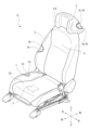
- FIG. 1 is a perspective view of a vehicle seat according to the present embodiment.
- FIG. 3 is a cross-sectional view of the headrest, showing a cushion material and a skin material. It is a perspective view of a seat frame and a blower device. It is a front view of a seat frame and a blower device.
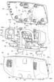
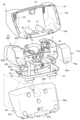
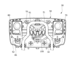
- FIG. 3 is an exploded perspective view of a pillar, a front cover, a rear cover, and a lower cover. It is an exploded perspective view of a pillar, a front cover, a rear cover, and a lower cover seen from another angle.
- FIG. 3 is an enlarged view of the main parts of the front cover, showing an opening.
- FIG. 1 is a diagram illustrating a method 1 for manufacturing a vehicle seat.
- 13A is a diagram showing a continuation of FIG. 13A.
- FIG. 2 is a diagram illustrating a method 2 for manufacturing a vehicle seat.
- 14A is a diagram showing a continuation of FIG. 14A.
- FIG. 14B is a figure which shows the continuation of FIG. 14B.
- the present embodiment is a vehicle seat that includes a headrest and left and right speakers provided inside the headrest, the headrest includes a speaker assembly for assembling the speakers, and the speaker assembly includes: It has left and right speaker holding parts that hold the left and right speakers in a state exposed to the front side of the seat, and a connecting part that connects the left and right speaker holding parts and is formed integrally with the left and right speaker holding parts.
- This relates to a vehicle seat whose main feature is that the Note that the side on which the seated person sits with respect to the seat back (headrest) of the vehicle seat is the front side of the seat.
- the vehicle seat S of this embodiment is a vehicle seat, and includes a seat body having a seat cushion 1, a seat back 2, and a headrest 3, and as shown in FIG.
- a blower device 4 is attached to the inside of the seat back 2 and blows air toward the seated person.
- a speaker 5 is attached to the inside of the headrest 3 and outputs sound to the seated person. It is equipped with a microphone 6 that receives sound and converts it into an electrical signal.
- the vehicle seat S also includes a control device 7 attached to the seat body, connected to the blower device 4, the speaker 5, and the microphone 6, and controlling the blower device 4, the speaker 5, and the microphone 6.
- the vehicle seat S includes a rail device that supports the seat body so as to be movable back and forth relative to the vehicle floor, a height link device that connects the seat body to the vehicle floor so as to be movable up and down, and a seat cushion 1 that is connected to the seat cushion 1.
- the vehicle may further include a reclining device that rotatably connects the seat back 2.
- the seat cushion 1 is a seating portion that supports a seated person from below, and includes a cushion frame 10 serving as a skeleton, a cushion material 1a placed on the cushion frame 10, and a cushion frame 10. and a skin material 1b that covers the cushion material 1a.
- the seat back 2 is a backrest that supports a seated person from behind, and is mainly composed of a back frame 20 serving as a skeleton, a cushion material 2a, and a skin material 2b. has been done.
- the headrest 3 is a head that supports the occupant's head from behind, and includes a headrest frame 30 serving as a skeleton, and cushioning materials 3a and 3b placed on the headrest frame 30. and skin materials 3c and 3d that cover the headrest frame 30 and cushion materials 3a and 3b.
- the cushioning material 3a is an elastic body made of an elastic material such as urethane.
- the second cushion material 3b is a three-dimensional network-like elastic body formed of three-dimensionally intertwined fibers.
- the second cushion material 3b has both the function of a cushion material and the function of transmitting the sound output from the speaker 5. Note that the second cushion material 3b may be formed to have higher acoustic transparency than the cushion material 3a, and is not limited to a three-dimensional net-like elastic body.
- the skin material 3c is a covering material made of a stretchable leather material or the like.
- the second skin material 3d is a covering material formed of three-dimensionally intertwined fibers.
- the second skin material 3d has both the function of a covering material and the function of transmitting the sound output from the speaker 5. Note that the second skin material 3d is not particularly limited as long as it has higher acoustic transparency than the skin material 3c.
- the cushion portions of the cushion material corresponding to the left and right speakers 5 and the microphone 6 in the front-rear direction of the seat serve as the second cushion material 3b.
- the rest of the cushion portion is a cushion material 3a.
- the skin portions corresponding to the left and right speakers 5 and microphones 6 in the front-rear direction of the seat are the second skin materials 3d.
- the other skin portion is the skin material 3c.
- cushion portion and the skin portion corresponding only to the speaker 5 may be the second cushion material 3b and the second skin material 3d, respectively.
- the entire cushion material and the entire skin material of the headrest 3 may be the second cushion material 3b and the second skin material 3d, respectively.
- the blower device 4 is attached to the front surface of the upper part of the back frame 20, as shown in FIGS. 3 and 4. Specifically, it is attached to the front surfaces of the connecting frame 23 and the rear frame 24 of the back frame 20 via attachment brackets 27 .
- the blower device 4 includes a blower main body 4a that supplies air, a duct 4b that allows air to pass through, and an outlet 4c that blows out air toward the back of a seated person.
- the blower main body 4a is arranged at the center of the upper part of the back frame 20.
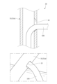
- the duct 4b extends from the blower main body 4a to the outside (right side) in the seat width direction, is bent so as to surround the pillar 31, and extends toward the front side of the seat.
- the air outlet 4c is formed at the extending end of the duct 4b.
- the blower device 4 (blower main body 4a) is connected to the control device 7 via a blower harness 4d.
- the blower harness 4d extends from the blower main body 4a to the outside (left side) in the seat width direction, is bent so as to surround the pillar 31, and extends downward.
- the speakers 5 are speaker units, and are provided inside the headrest frame 30, and are disposed on the left and right side portions of the headrest frame 30.
- the headrest frame 30 is attached to the front surface of the rear cover 50 via the speaker assembly 70 on the left and right sides.
- the microphone 6 is a microphone unit, and similarly to the speaker 5, it is arranged on the left and right side portions of the headrest frame 30, and is attached to the left and right sides via the speaker assembly 70.
- the speaker 5 and the microphone 6 are connected to the control device 7 via a speaker harness 100A and a microphone harness 100B, respectively, as shown in FIGS. 3 and 8 to 10.
- the harnesses 100A and 100B extend inward in the seat width direction from the speaker 5 and the microphone 6, respectively, and are combined into one harness 100, passing through the inside of the pillar 31 (left pillar 31) and extending downward. Details will be described later.
- the control device 7 is a device for controlling electrical components, and is attached to the bottom surface of the cushion frame 10 via a holder (not shown).
- the control device 7 is electrically connected to the blower device 4 via a blower harness 4d and a harness 100. Further, it is electrically connected to a speaker 5 and a microphone 6 via a harness 100 (harnesses 100A and 100B). Note that the control device 7 may be connected to these electrical components by wireless communication.
- the control device 7 is also connected to a battery (not shown), and controls the blower device 4, the speaker 5, and the microphone 6 to be supplied with electricity.
- the control device 7 is externally connected to, for example, an external terminal, such as a tablet terminal, a smartphone, a computer such as a PC, or an electrical device, and receives a predetermined control signal (control information). Then, the drive of the blower device 4, speaker 5, and microphone 6 is controlled based on the control signal. Note that the control device 7 may be attached to a different location inside the vehicle seat S, or may be attached to the outside of the vehicle seat S.
- the cushion frame 10 is composed of a substantially rectangular frame-like body, and includes cushion side frames arranged on the left and right sides and extending in the front-rear direction of the seat, and a front portion of each cushion side frame. It mainly consists of a pan frame to be constructed, a connecting frame that connects the rear portions of each cushion side frame, and a plurality of elastic springs that are hooked to the pan frame and the connecting frame and extend in a serpentine shape in the front and rear direction of the seat. It is configured.
- the control device 7 is attached to the bottom surface of the cushion frame 10 (pan frame).
- the back frame 20 is composed of a substantially rectangular frame-like body, and includes side frames 21 arranged on the left and right sides and extending in the vertical direction, and an upper end portion of each side frame 21.
- an inverted U-shaped upper frame 22 that connects the side frames 21, a lower frame (not shown) that connects the lower end portions of each side frame 21, and a lower portion of the left and right upper frames 22, extending in the seat width direction.
- It includes a plate-shaped connecting frame 23 and a plate-shaped rear frame 24 attached to the rear surface of the upper frame 22.
- the back frame 20 also includes left and right support wires 25 (occupant support wires) which are hooked onto the connecting frame 23 and the lower frame and extend in the vertical direction, and left and right support wires 25 (occupant support wires) which are disposed in the center of the back frame 20.
- the vehicle further includes a substantially rectangular support plate 26 (occupant support plate) that is held by the vehicle body 25 and supports the seated person from behind. Note that the left and right side frames 21, the upper frame 22, and the lower frame correspond to a "frame-shaped main body frame.”
- a mounting bracket 27 for mounting the blower device 4 is further attached to the front surfaces of the connection frame 23 and the rear frame 24.
- the central portion of the connecting frame 23 in the seat width direction has a concave shape that is concave toward the rear of the seat.
- the rear frame 24 is arranged to cover substantially the entire upper frame 22 and connection frame 23 from the rear.
- the mounting bracket 27 is attached to the front surface of the connection frame 23 from the front of the seat so as to be partially fitted therein, and is fixed to the connection frame 23 and the rear frame 24 with a plurality of fastening bolts 28 .
- the mounting bracket 27 is disposed between the left and right pillars 31 and the rear frame 24 in the front-rear direction of the seat. Further, the plurality of fastening bolts 28 are arranged so as to surround the blower device 4 (blower main body 4a) when viewed from the front of the seat. By doing so, the mounting rigidity of the blower device 4 can be increased.
- a harness holding portion 24a for holding the harness 100 is formed at the lower end of the rear frame 24. Further, a third harness attachment hole 24b (third harness attachment part) for attaching a third attachment clip 103 (third attached part) provided on the harness 100 is formed on the front surface of the harness holding part 24a. There is.
- the harness holding parts 24a hang down from the lower end of the rear frame 24, and are formed in plurality at intervals in the seat width direction. With the above configuration, the harness 100 extending from the speaker 5 and the microphone 6 can be suitably held. Further, interference between the harness 100 and other components can be suppressed.
- Left and right pillar guides 29 are assembled to the upper end of the upper frame 22 for attaching the left and right pillars 31 that serve as core members of the headrest 3.
- the pillar guide 29 is a guide member that is fixed to the back frame 20 and holds the pillar 31 movably in the vertical direction.
- the left and right pillar guides 29 are arranged at positions overlapping the mounting brackets 27 in the seat front-rear direction, and are arranged at different positions from the mounting brackets 27 in the seat width direction. Therefore, the design is such that the components are arranged in a compact manner while preventing the components from interfering with each other.
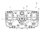
- the headrest frame 30 is assembled to an inverted U-shaped pillar 31, which is the core material of the headrest 3, and to the pillar 31, so as to sandwich the pillar 31 from the front and rear directions of the seat. It is mainly composed of a front cover 40 and a rear cover 50 which are arranged in the front cover 40 and a rear cover 50, and a lower cover 60 which is arranged so as to cover the pillar 31 from below.
- the front cover 40, the rear cover 50, and the lower cover 60 are arranged so as to cover the pillar 31, the speaker 5, the microphone 6, and the speaker assembly 70 from the outside, and are assembled with each other.
- the front cover 40, the rear cover 50, and the lower cover 60 correspond to the "main body of the headrest.”
- the pillars 31 are cylindrical support members that support the main body of the headrest 3, and are arranged at predetermined intervals in the seat width direction.
- the seat has left and right pillar extensions 31a extending downwardly toward the seat back 2, and a pillar connection part 31b connecting the upper ends of the left and right pillar extensions 31a and extending in the seat width direction. are doing.
- a harness insertion hole 32 for passing the harness 100 is formed in the outer peripheral surface of the pillar 31 (left pillar extension 31a).
- the harness insertion hole 32 is formed on the inner surface of the pillar extension part 31a in the seat width direction, and has a reverse tapered cross-sectional shape. Therefore, it is possible to easily insert the harness into the pillar. Moreover, unintentional deformation of the harness can be suppressed. Note that the cross-sectional shape of the harness insertion hole 32 may be tapered or linear.
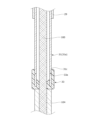
- a cylindrical cap member 33 that is more flexible than the metal pillar 31 is attached to the lower end of the pillar 31 (left pillar extension 31a).
- the cap member 33 is also called a pillar end cap, and is, for example, a rubber cap, and is attached to the lower end of the pillar 31 so as to be detachable from below.
- the cap member 33 has a support protrusion 33a formed on its inner peripheral surface and capable of being hooked into a support groove 31c provided on the outer peripheral surface of the pillar 31.
- the cap member 33 is attached to the support groove 31c by the support protrusion 33a, and is attached to cover the end surface, inner surface, and outer surface of the lower end of the pillar 31. Therefore, when the harness 100 is exposed from the lower end of the pillar 31, the harness 100 can be protected by the cap member 33.
- the front cover 40 is a cover made of resin, and is integrally assembled with the rear cover 50 and the lower cover 60. Specifically, the front cover 40 is assembled with the rear cover 50 in the seat front-rear direction, and then assembled with the lower cover 60 in the up-down direction.
- the front cover 40 is a plate body including a front wall portion 40a, a top wall portion 40b, left and right side walls 40c, and a bottom wall portion 40d.
- the front cover 40 also includes a cover center section 41 provided at the center in the seat width direction, and left and right covers that are arranged on the left and right outer sides of the cover center section 41 and protrude toward the front of the seat relative to the cover center section 41.
- a side portion 42 is provided.
- a locking piece 43 and a locking hole 43a that protrude toward the rear of the seat and can be locked to the rear cover 50 are formed at the upper end and both left and right ends.
- a first pillar latching recess 44 is formed at the upper end of the rear surface of the front cover 40, which projects toward the rear of the seat and is attachable to the rear cover 50 (first pillar latching clip 56).
- left and right second pillar latching recesses 45 that can be attached to the rear cover 50 (left and right second pillar latching clips 57) are formed at the rear end of the bottom surface of the front cover 40.
- Left and right assembly bosses 46 (assembly portions) that are recessed toward the rear of the seat and that can be assembled to the rear cover 50 (assembly hole 58) are formed in the lower part of the front surface of the front cover 40.
- the locking piece 43 (locking hole 43a) is removably locked to the locking claw 55, and the pillar locking recesses 44 and 45 are removably lockable to the pillar locking clips 56 and 57.
- the front cover 40 is permanently fixed to the rear cover 50 by bolting the assembly boss 46 into the assembly hole 58.
- An engagement hole 47 is formed in the bottom surface of the front cover 40 so as to penetrate in the vertical direction and can be assembled to the lower cover 60 (engagement hook 62).
- a fixing hole 48 (fixing portion) is formed at the lower end of the front cover 40 so as to protrude downward and is fixed to the lower cover 60 (fixing boss 63).
- the front cover 40 is temporarily fixed to the lower cover 60 by the engagement hole 47 being removably engaged with the engagement hook 62.
- the front cover 40 is integrally fixed to the lower cover 60 by bolting the fixing boss 63 in contact with the fixing hole 48 .
- the fixing boss 63 is brought into contact with the fixing hole 48 of the front cover 40 and the fixing hole 59 of the rear cover 50 in a state where they are overlapped like a tally. Thereafter, the front cover 40, rear cover 50, and lower cover 60 are permanently fixed by bolting.
- the left and right cover side portions 42 have grid-shaped openings 49 formed at positions corresponding to the left and right speakers 5 in the front-rear direction of the seat.
- the opening 49 is also called a speaker grill, and has a plurality of passage holes through which the sound output from the speaker 5 passes.
- the openings 49 are formed in a grid shape, but are not particularly limited, and may be formed in a net shape, and are not particularly limited as long as they have a shape that allows sound to pass through.
- reinforcing ribs 49a are formed along a lattice-shaped frame on the rear surface of the opening 49. As shown in FIG.
- the reinforcing ribs 49a extend in the seat width direction and the up-down direction.
- the reinforcing rib 49a extending in the seat width direction is connected to a wall portion 41a (partition wall portion) between the cover center portion 41 and the cover side portion 42.
- the rear cover 50 is a cover made of resin, and is integrally assembled with the front cover 40 and the lower cover 60.
- the rear cover 50 is assembled with the front cover 40 in the seat front-rear direction, and then is assembled with the lower cover 60 in the up-down direction.
- the rear cover 50 is a plate body including a rear wall portion 50a, a top wall portion 50b, left and right side walls 50c, and a bottom wall portion 50d.
- left and right attachment bosses 51 (attachment portions) are formed that protrude toward the front of the seat and are attachable to the speaker assembly 70 (left and right cover attachment holes 91).
- left and right second attachment bosses 52 (second attachment portions) that can be attached to the speaker assembly 70 (left and right second cover attachment holes 85) are formed at the lower end of the front surface of the rear cover 50.
- a third attachment boss 53 (third attachment portion) that can be attached to the speaker assembly 70 (third cover attachment hole 92) is formed in the center of the front surface of the rear cover 50.
- the left and right second attachment bosses 52 are arranged outside the left and right attachment bosses 51 in the seat width direction.
- the third attachment boss 53 is arranged inside the left and right attachment bosses 51.
- the speaker assembly 70 is attached to the front surface of the rear cover 50. Specifically, the speaker assembly 70 (third cover attachment hole 92) is temporarily fixed to the rear cover 50 (third attachment boss 53). Then, the cover mounting holes 91 and 85 are permanently fixed to the mounting bosses 51 and 52 using mounting bolts.
- a second harness attachment hole 54 for attaching the harness 100 is formed at the lower end of the front surface of the rear cover 50. By doing so, the harness 100 can be suitably held by the rear cover 50.
- locking claws 55 that protrude toward the front of the seat and can be locked to the front cover 40 (locking pieces 43) are formed at the upper end and both left and right ends.
- a first pillar latching clip 56 (first pillar latching portion) is formed at the upper end of the front surface of the rear cover 50 and projects toward the front of the seat and is attachable to the front cover 40 (first pillar latching recess 44).
- left and right second pillar latching clips 57 (second pillar latching portions) that can be assembled to the front cover 40 (second pillar latching recess 45) are formed at the front end of the bottom surface of the rear cover 50.
- left and right assembly holes 58 (assembled parts) that are recessed toward the rear of the seat and that can be assembled to the front cover 40 (left and right assembly bosses 46).
- the pillar retaining clip 56 is arranged at a position overlapping the left and right attachment bosses 51 in the vertical direction. As shown in FIG. 8, the pillar retaining clips 56 and 57 are arranged at positions sandwiching the left and right second attachment bosses 52 and third attachment bosses 53 in the vertical direction. The pillar retaining clip 56 is arranged between the left and right attachment bosses 51 and 52 in the seat width direction. The second pillar latching clip 57 is arranged between the left and right attachment bosses 52 in the seat width direction. The first pillar latching clip 56 is formed so as to clamp the pillar 31 in the vertical direction, and the second pillar latching clip 57 is formed so as to clamp the pillar 31 in the seat width direction.
- the pillar 31 and the front cover 40 are assembled to the front surface of the rear cover 50. More specifically, first, the pillar 31 is latched to the rear cover 50 (pillar latching clips 56, 57). The front cover 40 (locking piece 43, pillar locking recesses 44, 45) is locked to the rear cover 50 (locking claw 55, pillar locking clips 56, 57). Then, the front cover 40 (assembly boss 46) is assembled with bolts to the rear cover 50 (assembly hole 58). Note that the pillar 31 is held between the front cover 40 (pillar latching recesses 44 and 45) and the rear cover 50 (pillar latching clips 56 and 57) in the seat longitudinal direction.
- a gap filling member 34 is attached to fill the gap.
- the gap filling member 34 is a flexible (elastic) member. By interposing the gap filling member 34, it is possible to suppress rattling of the pillar 31 or the rear cover 50. Moreover, generation of abnormal noise between the pillar 31 and the rear cover 50 can be suppressed.
- the gap filling member 34 may be a nonwoven fabric, or may be a dowel, a wrinkle, or a rib formed on the outer periphery of the pillar 31 or the outer surface of the rear cover 50.
- a fixing hole 59 (fixing portion) is formed at the lower end of the rear cover 50 so as to protrude downward and is fixed to the lower cover 60 (fixing boss 63).
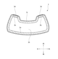
- the lower cover 60 is a cover made of resin, and is integrally assembled with the front cover 40 and the rear cover 50. arranged to cover.
- the lower cover 60 is a plate body having a downwardly curved shape. Specifically, the outer edge portion of the lower cover 60 is formed to protrude upward.
- Left and right pillar insertion holes 61 (pillar insertion portions) for passing the pillars 31 (left and right pillar extension portions 31a) through the left and right side portions of the upper surface of the lower cover 60 are formed. By doing so, the lower cover 60 can be assembled to the pillar 31 hooked to the rear cover 50.
- An engagement hook 62 is formed in the center of the upper surface of the lower cover 60 so as to protrude upward and can be detachably engaged with the front cover 40 (engagement hole 47).
- a plurality of fixing bosses 63 (fixed parts) are formed on the upper surface of the lower cover 60 so as to protrude upward and can be fixed to the front cover 40 (fixing holes 48) and the rear cover 50 (fixing holes 59).
- the fixing bosses 63 are arranged at intervals in the seat width direction so as to sandwich the engagement hook 62 therebetween.
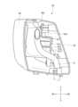
- the speaker assembly 70 is a resin box (casing), and is provided on the left and right side portions of the headrest 3, and is attached to the left and right speakers 5.
- Left and right speaker holding parts 80 that hold the microphone 6 in a state exposed to the front side of the seat, and a connecting part 90 that connects the left and right speaker holding parts 80 and is integrally formed with the left and right speaker holding parts 80.
- “Formed as one piece” includes a state in which the speaker holding part 80 and the connecting part 90 are integrally molded, or are integrated by welding or the like. Furthermore, it includes a state in which they are assembled with each other without requiring separate mounting members (mounting plates, mounting bolts, etc.).
- the speaker assembly 70 is arranged so that the left and right speaker holding parts 80 cover the pillar 31 from both sides in the seat width direction, and the connecting part 90 covers the pillar 31 from the rear side of the seat. By doing so, for example, it is possible to suppress the speaker assembly 70 and the speaker 5 from shaking (moving) in the left-right direction and the front-back direction with respect to the headrest 3 (pillar 31) while the vehicle is running. can.
- the speaker holding section 80 has a function of accommodating the speaker 5 and the microphone 6, and a function of accommodating the harness 100 connected to the speaker 5 and the microphone 6, respectively. are doing.
- the speaker holding portion 80 includes a central wall portion 80a, a protruding wall portion (a top wall portion 80b, a bottom wall portion 80c, and a side wall portion 80d) that protrudes from the outer edge portion of the central wall portion 80a toward the front of the seat, and a central wall portion 80a. It has an extending wall portion (rear upper wall portion 80e, rear bottom wall portion 80f, left and right rear side wall portions 80g) extending rearward from the outer edge portion of the seat.
- the speaker holding portion 80 further includes a second extending wall portion (a lower front wall portion 80h, a flange wall portion 80i, and a reinforcing wall portion 80j) extending downward from the rear bottom wall portion 80f.
- the upper wall portion 80b protrudes forward from the upper end portion of the main body (center wall portion 80a) of the speaker holding portion 80.
- the bottom wall portion 80c projects forward from the lower end of the center wall portion 80a.
- the side wall portion 80d projects forward from the side end (right end) of the center wall portion 80a.
- Each front end portion is in contact with the rear surface of the front cover 40. By doing so, the front cover 40 can be suitably supported by the speaker assembly 70 when an external load is applied from the front side of the seat.
- these wall portions 80b, 80c, and 80d do not necessarily need to be in contact with the front cover 40, and may be arranged so as to be able to come into contact with the front cover 40.
- the speaker holding part 80 is provided at the front position thereof, and has an accommodation recess 81 for accommodating the speaker 5 and the microphone 6, and is provided at the rear position of the speaker holding part 80, It has a rear accommodation recess 82 in which the harness 100 is accommodated, and a lid part 83 that covers the rear accommodation recess 82 from the rear of the seat.
- the speaker 5 and the microphone 6 are housed in the housing recess 81 from the front side of the seat, and are held in an exposed state on the front side of the seat.
- the speaker 5 is housed so as to pass through the bottom surface of the housing recess 81 and is held in a state where it is exposed from the speaker holding part 80 to the front side of the seat and the rear side of the seat.
- the microphone 6 is accommodated in a recess 81a provided on the bottom surface of the accommodation recess 81, and is held in a state where it is exposed from the speaker holding section 80 toward the front side of the seat.
- the speaker 5 penetrates the housing bottom surface of the housing recess 81 and the housing bottom surface of the rear housing recess 82 in the seat front-rear direction. In other words, the speaker 5 can be said to be housed in the housing recess 81 and the rear housing recess 82 .
- the speaker holding section 80 holds the speaker 5 in a state exposed to the front side of the seat, and also moves the microphone 6 to the front side of the seat at a position below the speaker 5. It is held in an exposed position. Further, the speaker 5 and the microphone 6 are arranged between the upper end of the attachment boss 51 and the lower end of the connecting portion 90 in the vertical direction. By doing so, the rear cover 50, the speaker assembly 70, the speaker 5, and the microphone 6 can be firmly attached to the pillar 31 serving as the core material of the headrest 3.
- a harness 100A connected to the speaker 5 and a harness 100B connected to the microphone 6 are accommodated in the rear accommodation recess 82.
- the rear housing recess 82 is covered by a lid 83 from the rear of the seat. More specifically, as shown in FIG. 6, bolt holes 82a and 83a are formed in the lower end of the rear housing recess 82 and the lower end of the lid 83, respectively.
- the lid part 83 is attached to the rear accommodation recess 82 by attaching the fixing bolt with these bolt holes 82a and 83a communicating with each other.
- each of the extending ends of the harnesses 100A and 100B protrudes inward in the seat width direction from a gap formed on the inner surface of the rear accommodation recess 82.
- a chamfered portion 84 is formed at a corner of the housing recess 81 (a corner at the inner lower end). By doing so, the rigidity of the housing recess 81 can be increased. Furthermore, interference between the housing recess 81 and other components can be suppressed.
- the lower end of the speaker holding portion 80 has left and right second cover attachment holes 85 that can be attached to the rear cover 50 (left and right second attachment bosses 52). It is formed.
- the second cover attachment hole 85 is located directly below the speaker 5 and microphone 6. Moreover, it is arranged at a position outside the pillar 31 in the seat width direction.
- the connecting portion 90 is a connecting bracket that is elongated in the seat width direction, and is a portion for assembling the speaker assembly 70 to the pillar 31. 5 (microphone 6).
- the connecting portion 90 includes a rear wall portion 90a that extends in the width direction of the seat and connects the left and right speaker holding portions 80, and an upper wall portion 90b that extends toward the front of the seat from the upper end of the rear wall portion 90a. It has a front wall part 90c extending upward from the front end of the upper wall part 90b.
- Left and right cover attachment holes 91 that can be attached to the rear cover 50 are formed at the upper end of the connecting portion 90 (front wall portion 90c). Further, a third cover attachment hole 92 that can be attached to the rear cover 50 (third attachment boss 53) is formed in the center of the connecting portion (rear wall portion 90a).
- Harness guide parts 93 and 94 are formed on the rear surface of the connecting part 90 (front wall part 90c) so as to protrude toward the rear of the seat and guide the harness 100.
- the harness guide section 93 and the second harness guide section 94 are arranged in a row in the seat width direction, and are arranged at a position facing the rear accommodation recess 82 .
- the harness guide parts 93 and 94 are U-shaped and support the harness 100 from above, below, and from the front after the harness 100 is attached from the rear of the seat.
- a harness attachment hole for attaching an attachment clip 101 provided on the harness 100 to support the harness 100 is provided on the front surface of the central portion of the connecting portion 90 (rear wall portion 90a).
- a plurality of 95 are formed.
- the front surfaces of the left and right side portions of the connecting portion 90 protrude toward the front of the seat toward the pillar 31 and come into contact with the rear surface of the pillar 31.
- a contact rib 97 is formed.
- a plurality of harness attachment holes 95 are arranged in a row in the seat width direction.
- the reinforcing ribs 96 extend laterally and laterally outwardly than the plurality of harness attachment holes 95 in the seat width direction, and protrude toward the opposite side (the seat rear side) from the harness 100 side (the seat front side). Therefore, when forming the reinforcing ribs 96 around the harness attachment hole 95, the reinforcing ribs can be arranged while suppressing interference between the harness 100 and the reinforcing ribs 96.
- the contact ribs 97 are formed on the left and right sides at predetermined intervals in the sheet width direction.
- the left and right contact ribs 97 are arranged so as to sandwich the harness attachment hole 95 therebetween.
- the abutting rib 97 connects the first abutting rib 97a and the second abutting rib 97b, which are arranged at intervals in the vertical direction, and the first abutting rib 97a and the second abutting rib 97b. It has a connecting rib 97c.
- the first abutting rib 97a, the second abutting rib 97b, and the connecting rib 97c are in contact with the rear surface of the pillar 31, respectively, as shown in FIG. Note that the contact rib 97 does not necessarily have to be in contact with the pillar 31, and may be arranged so as to be able to come into contact with the pillar 31.
- the harnesses 100A and 100B extend inward in the seat width direction from the speaker 5 and the microphone 6, respectively, and are combined into one harness 100, ) and extends downward toward the seat back 2. It further extends from the seat back 2 toward the seat cushion 1 and is connected to a control device 7 provided on the seat cushion 1.
- Harnesses 100A and 100B each have an attachment clip 101 that can be attached to speaker assembly 70 (harness attachment hole 95). Specifically, it has a coupler at a position facing the harness attachment hole 95, and has an attachment clip 101 provided on the coupler. Further, the harness 100 has a second attachment clip 102 that can be attached to the rear cover 50 (second harness attachment hole 54). Further, the harness 100 has a third attachment clip 103 that is provided inside the seat back 2 and that can be attached to the rear frame 24 (third harness attachment hole 24b). Further, the harness 100 includes a harness guide 104 that is provided inside the seat back 2 and covers the harness 100 (harness main body).
- the harness 100A (100B) is connected to the speaker 5 (microphone 6) and is accommodated in the rear accommodation recess 82.
- a harness 100A extending from the speaker 5 extends inward in the seat width direction from the rear accommodation recess 82 and is supported by harness guide parts 93 and 94.
- the harness 100A extends downward from the harness guide portions 93 and 94 and is supported by the harness attachment hole 95.
- the attachment clip 101 is attached to the harness attachment hole 95.
- the harness 100A and the harness 100B extend downward and are combined into one harness 100.
- the combined harness 100 is supported by the second harness attachment hole 54.
- the second attachment clip 102 is attached to the rear cover 50 (second harness attachment hole 54).
- the harness 100 extends from the second harness attachment hole 54 toward one side (left side) in the seat width direction toward the pillar 31 (left pillar extension 31a).
- the harness 100 is passed into the pillar 31 through a harness insertion hole 32 provided in the pillar 31, and extends downward toward the seat back.
- the harness 100 and the blower harness 4d are combined into one and extend downward toward the seat cushion 1.
- the combined harness 100 is connected to a control device 7 provided inside the seat cushion 1.
- harnesses 100A and 100B extend from the speaker 5 and microphone 6, respectively. It may be devised to prevent these harnesses 100A and 100B from being assembled incorrectly.
- the thickness of the harness 100A connected to the speaker 5 and the thickness of the harness 100B connected to the microphone 6 may be changed. That is, the thickness of the harness 100A may be made thicker than the thickness of the harness 100B. Or you can make it thinner.
- the coupler (connector) of the harness 100A and the coupler (connector) of the harness 100B may have different shapes, different sizes, different colors, and different marks. As another mark, the mark “S (Speaker)" may be given to the harness 100A, and the mark “M (Microfone)” may be given to the harness 100B.
- the left and right harnesses 100 are combined into one and passed through the left pillar 31.
- the harness 100 connected to the left speaker 5 extends from the left speaker toward the pillar 31, and is inserted into the pillar 31 through the harness insertion hole 32 provided in the left pillar extension 31a. It may be passed through the inside of.
- the harness 100 connected to the right speaker 5 may be passed into the pillar 31 through the harness insertion hole 32 provided in the right pillar extension 31a.
- cover attachment holes 91, 85, and 92 are attached to the left and right attachment bosses 51, 52, and 53. More specifically, the cover mounting holes 91 and 85 are bolted to the mounting bosses 51 and 52. Note that the third cover attachment hole 92 is hooked onto the third attachment boss 53 to temporarily fix it. Then, the pillar 31 is latched onto the rear cover 50. Specifically, the pillar 31 is latched to the pillar latching clips 56 and 57. Then, the harness 100 is passed through the inside of the pillar 31. Then, the front cover 40 is assembled to the rear cover 50, and the lower cover 60 is assembled from below with the front cover 40 and the rear cover 50 assembled.
- the speaker 5 and the microphone 6 are assembled to the speaker assembly 70.
- the speaker assembly 70 is "temporarily fixed” to the rear cover 50.
- the third cover attachment hole 92 is hooked onto the third attachment boss 53 for temporary fixation.
- the pillar 31 is latched onto the rear cover 50.
- the speaker assembly 70 is pressed against the rear cover 50 by the pillar 31.
- the speaker assembly 70 is "finally fixed” to the rear cover 50.
- the cover mounting holes 91 and 85 are bolted to the mounting bosses 51 and 52.
- the harness 100 is passed through the inside of the pillar 31.
- the front cover 40 is assembled to the rear cover 50, and the lower cover 60 is assembled from below with the front cover 40 and the rear cover 50 assembled.
- the headrest frame 30 includes a front cover 40, a rear cover 50, and a lower cover 60, but this is not particularly limited.
- the lower cover 60 may be unnecessary.
- the front cover 40 or the rear cover 50 may be unnecessary.
- the engagement hole 47 of the front cover 40 and the engagement hook 62 of the lower cover 60 engage with each other, but the engagement structure is not particularly limited. It's not something you can do.
- the engagement hole 47 may be replaced with an engagement recess.
- an engagement structure other than an engagement hole and an engagement hook may be used. That is, the engaged portion of the front cover 40 and the engaging portion of the lower cover 60 may be engaged with each other using other engagement structures.
- the structure of the locking part and the locked part, the structure of the attaching part and the attached part, the structure of the assembly part and the assembled part, the structure of the fixing part and the fixed part, etc. may be changed as appropriate. Also good.
- the left and right speaker holding parts 80 and the connecting part 90 are integrally formed in the speaker assembly 70, but this is not particularly limited.
- the left and right speaker holding parts 80 and the connecting part 90 may be formed separately. That is, the speaker holding part 80 and the connecting part 90 may be connected via an attachment member.
- the speaker holding part 80 has the housing recess 81 and the rear housing recess 82, but it may have either one of the housing recesses.
- the speaker holding portion 80 may have only the rear accommodation recess 82 (accommodation recess), and may accommodate the speaker 5, the microphone 6, and the harness 100.
- the speaker 5 and the microphone 6 are preferably disposed so as to pass through the housing bottom surface of the rear housing recess 82 and be exposed to the front side of the seat.
- a vehicle seat used in a car was described as a specific example, but there is no particular limitation, and the seat can also be used as a seat for vehicles such as trains and buses, as well as seats for vehicles such as airplanes and ships. be able to.
- the vehicle seat according to the present invention has been mainly described.
- the embodiments described above are merely examples for facilitating understanding of the present invention, and do not limit the present invention.
- the present invention may be modified and improved without departing from its spirit, and it goes without saying that the present invention includes equivalents thereof.
Landscapes
- Engineering & Computer Science (AREA)
- Mechanical Engineering (AREA)
- Aviation & Aerospace Engineering (AREA)
- Transportation (AREA)
- Physics & Mathematics (AREA)
- Acoustics & Sound (AREA)
- Signal Processing (AREA)
- Seats For Vehicles (AREA)
- Fittings On The Vehicle Exterior For Carrying Loads, And Devices For Holding Or Mounting Articles (AREA)
- Chair Legs, Seat Parts, And Backrests (AREA)
- Passenger Equipment (AREA)
- Details Of Audible-Bandwidth Transducers (AREA)
Priority Applications (2)
| Application Number | Priority Date | Filing Date | Title |
|---|---|---|---|
| US18/868,499 US20250353418A1 (en) | 2022-05-24 | 2023-05-23 | Conveyance seat |
| CN202380041954.4A CN119255933A (zh) | 2022-05-24 | 2023-05-23 | 交通工具用座椅 |
Applications Claiming Priority (4)
| Application Number | Priority Date | Filing Date | Title |
|---|---|---|---|
| US202263345133P | 2022-05-24 | 2022-05-24 | |
| US63/345,133 | 2022-05-24 | ||
| JP2022106697A JP2023172816A (ja) | 2022-05-24 | 2022-06-30 | 乗り物用シート |
| JP2022-106697 | 2022-06-30 |
Publications (1)
| Publication Number | Publication Date |
|---|---|
| WO2023228960A1 true WO2023228960A1 (ja) | 2023-11-30 |
Family
ID=88919347
Family Applications (1)
| Application Number | Title | Priority Date | Filing Date |
|---|---|---|---|
| PCT/JP2023/019225 Ceased WO2023228960A1 (ja) | 2022-05-24 | 2023-05-23 | 乗り物用シート |
Country Status (4)
| Country | Link |
|---|---|
| US (1) | US20250353418A1 (https=) |
| JP (8) | JP2023172818A (https=) |
| CN (1) | CN119255933A (https=) |
| WO (1) | WO2023228960A1 (https=) |
Families Citing this family (1)
| Publication number | Priority date | Publication date | Assignee | Title |
|---|---|---|---|---|
| US20260021757A1 (en) * | 2024-07-19 | 2026-01-22 | Harman Becker Automotive Systems Gmbh | System, apparatus, and/or method for providing a headrest with one or more loudspeakers for improved audio performance |
Citations (2)
| Publication number | Priority date | Publication date | Assignee | Title |
|---|---|---|---|---|
| JP2017525456A (ja) * | 2014-08-07 | 2017-09-07 | ボーズ・コーポレーションBose Corporation | スピーカー付きヘッドレスト及びヘッドレストクッション部材の製造方法 |
| JP2021510990A (ja) * | 2018-01-24 | 2021-04-30 | アスク インダストリーズ ソシエタ ペル アツィオーニAsk Industries Societa’ Per Azioni | 車両シート用のラウドスピーカーを伴うヘッドレスト |
Family Cites Families (8)
| Publication number | Priority date | Publication date | Assignee | Title |
|---|---|---|---|---|
| JP5118890B2 (ja) * | 2007-05-29 | 2013-01-16 | 株式会社イノアックコーポレーション | ヘッドレスト及びその製造方法 |
| US8556342B2 (en) * | 2010-12-23 | 2013-10-15 | Nissan North America, Inc. | Headrest wire harness routing guide assembly |
| JP6049447B2 (ja) * | 2012-12-27 | 2016-12-21 | 日本発條株式会社 | 車両用シートのワイヤハーネス配策構造 |
| US10721554B2 (en) * | 2018-01-12 | 2020-07-21 | Harman International Industries, Incorporated | Audio directing loudspeaker grill |
| US11535136B2 (en) * | 2019-03-08 | 2022-12-27 | Harman International Industries, Incorporated | Headrest with integrated nose and loudspeaker enclosure |
| JP7431674B2 (ja) * | 2020-06-10 | 2024-02-15 | 日本発條株式会社 | ヘッドレスト用スリーブ及びヘッドレスト |
| CN115996863A (zh) * | 2020-08-31 | 2023-04-21 | 提爱思科技股份有限公司 | 头枕 |
| DE102021112215A1 (de) * | 2021-02-16 | 2022-08-18 | Adient Engineering and IP GmbH | Kopfstütze für einen Fahrzeugsitz und Fahrzeugsitz |
-
2022
- 2022-06-30 JP JP2022106699A patent/JP2023172818A/ja active Pending
- 2022-06-30 JP JP2022106697A patent/JP2023172816A/ja active Pending
- 2022-06-30 JP JP2022106698A patent/JP2023172817A/ja active Pending
-
2023
- 2023-02-13 JP JP2023020230A patent/JP7538446B2/ja active Active
- 2023-02-13 JP JP2023020229A patent/JP7538445B2/ja active Active
- 2023-02-13 JP JP2023020231A patent/JP7488495B2/ja active Active
- 2023-05-23 WO PCT/JP2023/019225 patent/WO2023228960A1/ja not_active Ceased
- 2023-05-23 US US18/868,499 patent/US20250353418A1/en active Pending
- 2023-05-23 CN CN202380041954.4A patent/CN119255933A/zh active Pending
-
2024
- 2024-05-08 JP JP2024076025A patent/JP7787446B2/ja active Active
-
2025
- 2025-12-03 JP JP2025226971A patent/JP2026031675A/ja active Pending
Patent Citations (2)
| Publication number | Priority date | Publication date | Assignee | Title |
|---|---|---|---|---|
| JP2017525456A (ja) * | 2014-08-07 | 2017-09-07 | ボーズ・コーポレーションBose Corporation | スピーカー付きヘッドレスト及びヘッドレストクッション部材の製造方法 |
| JP2021510990A (ja) * | 2018-01-24 | 2021-04-30 | アスク インダストリーズ ソシエタ ペル アツィオーニAsk Industries Societa’ Per Azioni | 車両シート用のラウドスピーカーを伴うヘッドレスト |
Also Published As
| Publication number | Publication date |
|---|---|
| JP2023172818A (ja) | 2023-12-06 |
| JP2023172816A (ja) | 2023-12-06 |
| JP2026031675A (ja) | 2026-02-24 |
| JP2023172875A (ja) | 2023-12-06 |
| JP7538445B2 (ja) | 2024-08-22 |
| JP7787446B2 (ja) | 2025-12-17 |
| JP2023172874A (ja) | 2023-12-06 |
| JP2023172873A (ja) | 2023-12-06 |
| US20250353418A1 (en) | 2025-11-20 |
| JP7538446B2 (ja) | 2024-08-22 |
| CN119255933A (zh) | 2025-01-03 |
| JP7488495B2 (ja) | 2024-05-22 |
| JP2023172817A (ja) | 2023-12-06 |
| JP2024097902A (ja) | 2024-07-19 |
Similar Documents
| Publication | Publication Date | Title |
|---|---|---|
| JP6650477B2 (ja) | 乗物用シート | |
| JP6627607B2 (ja) | 車両用シート | |
| JP2026031675A (ja) | 乗り物用シート | |
| JP2019001280A (ja) | 乗物用シート | |
| JP2017226376A (ja) | 乗物用シート | |
| JP2022162037A (ja) | 乗物用シート | |
| WO2023228961A1 (ja) | 乗り物用シート | |
| JP7259627B2 (ja) | 乗物用のスピーカー構造 | |
| JP7274878B2 (ja) | 乗物用シート | |
| JP5467762B2 (ja) | 乗り物用シート構造 | |
| JP5414112B2 (ja) | 車両用シート | |
| JP7656231B2 (ja) | ヘッドレスト | |
| JP7205287B2 (ja) | 乗物用シートの下部構造 | |
| JP7707222B2 (ja) | 乗物用シート | |
| CN113365532B (zh) | 交通工具座椅 | |
| JP2026062416A (ja) | 乗り物用シート | |
| JP2010247822A (ja) | 車両用シート構造 | |
| JP2026042508A (ja) | 乗物用シート | |
| JP2025060374A (ja) | 乗り物用シート | |
| WO2024135689A1 (ja) | 乗り物用シート | |
| JP2026042507A (ja) | 乗物用シート及び乗物用シートの製造方法 | |
| JP2021030946A (ja) | 乗物用シート | |
| JP2008092989A (ja) | 車両用乗員シート | |
| JP2018062238A (ja) | 乗物用シート |
Legal Events
| Date | Code | Title | Description |
|---|---|---|---|
| 121 | Ep: the epo has been informed by wipo that ep was designated in this application |
Ref document number: 23811832 Country of ref document: EP Kind code of ref document: A1 |
|
| WWE | Wipo information: entry into national phase |
Ref document number: 202380041954.4 Country of ref document: CN |
|
| WWE | Wipo information: entry into national phase |
Ref document number: 18868499 Country of ref document: US |
|
| NENP | Non-entry into the national phase |
Ref country code: DE |
|
| WWP | Wipo information: published in national office |
Ref document number: 202380041954.4 Country of ref document: CN |
|
| 122 | Ep: pct application non-entry in european phase |
Ref document number: 23811832 Country of ref document: EP Kind code of ref document: A1 |
|
| WWP | Wipo information: published in national office |
Ref document number: 18868499 Country of ref document: US |