WO2023228960A1 - 乗り物用シート - Google Patents
乗り物用シート Download PDFInfo
- Publication number
- WO2023228960A1 WO2023228960A1 PCT/JP2023/019225 JP2023019225W WO2023228960A1 WO 2023228960 A1 WO2023228960 A1 WO 2023228960A1 JP 2023019225 W JP2023019225 W JP 2023019225W WO 2023228960 A1 WO2023228960 A1 WO 2023228960A1
- Authority
- WO
- WIPO (PCT)
- Prior art keywords
- speaker
- seat
- pillar
- cover
- headrest
- Prior art date
Links
- 230000004308 accommodation Effects 0.000 claims description 26
- 230000000149 penetrating effect Effects 0.000 claims 1
- 239000000463 material Substances 0.000 description 43
- 238000003780 insertion Methods 0.000 description 11
- 230000037431 insertion Effects 0.000 description 11
- 230000003014 reinforcing effect Effects 0.000 description 10
- 238000004519 manufacturing process Methods 0.000 description 9
- 210000000078 claw Anatomy 0.000 description 5
- 239000011162 core material Substances 0.000 description 5
- 238000010586 diagram Methods 0.000 description 5
- 238000000034 method Methods 0.000 description 5
- 238000009434 installation Methods 0.000 description 4
- 239000011347 resin Substances 0.000 description 4
- 229920005989 resin Polymers 0.000 description 4
- 230000002093 peripheral effect Effects 0.000 description 3
- 239000000835 fiber Substances 0.000 description 2
- 230000002787 reinforcement Effects 0.000 description 2
- JOYRKODLDBILNP-UHFFFAOYSA-N Ethyl urethane Chemical compound CCOC(N)=O JOYRKODLDBILNP-UHFFFAOYSA-N 0.000 description 1
- 230000002159 abnormal effect Effects 0.000 description 1
- 239000000853 adhesive Substances 0.000 description 1
- 230000001070 adhesive effect Effects 0.000 description 1
- 239000003086 colorant Substances 0.000 description 1
- 238000004891 communication Methods 0.000 description 1
- 239000013013 elastic material Substances 0.000 description 1
- 230000005611 electricity Effects 0.000 description 1
- 230000002452 interceptive effect Effects 0.000 description 1
- 239000010985 leather Substances 0.000 description 1
- 239000002184 metal Substances 0.000 description 1
- 239000004745 nonwoven fabric Substances 0.000 description 1
- 238000005192 partition Methods 0.000 description 1
- 238000003466 welding Methods 0.000 description 1
- 230000037303 wrinkles Effects 0.000 description 1
Images


Classifications
-
- A—HUMAN NECESSITIES
- A47—FURNITURE; DOMESTIC ARTICLES OR APPLIANCES; COFFEE MILLS; SPICE MILLS; SUCTION CLEANERS IN GENERAL
- A47C—CHAIRS; SOFAS; BEDS
- A47C7/00—Parts, details, or accessories of chairs or stools
- A47C7/36—Support for the head or the back
- A47C7/38—Support for the head or the back for the head
-
- B—PERFORMING OPERATIONS; TRANSPORTING
- B60—VEHICLES IN GENERAL
- B60N—SEATS SPECIALLY ADAPTED FOR VEHICLES; VEHICLE PASSENGER ACCOMMODATION NOT OTHERWISE PROVIDED FOR
- B60N2/00—Seats specially adapted for vehicles; Arrangement or mounting of seats in vehicles
- B60N2/80—Head-rests
- B60N2/879—Head-rests with additional features not related to head-rest positioning, e.g. heating or cooling devices or loudspeakers
-
- B—PERFORMING OPERATIONS; TRANSPORTING
- B60—VEHICLES IN GENERAL
- B60R—VEHICLES, VEHICLE FITTINGS, OR VEHICLE PARTS, NOT OTHERWISE PROVIDED FOR
- B60R11/00—Arrangements for holding or mounting articles, not otherwise provided for
- B60R11/02—Arrangements for holding or mounting articles, not otherwise provided for for radio sets, television sets, telephones, or the like; Arrangement of controls thereof
-
- H—ELECTRICITY
- H04—ELECTRIC COMMUNICATION TECHNIQUE
- H04R—LOUDSPEAKERS, MICROPHONES, GRAMOPHONE PICK-UPS OR LIKE ACOUSTIC ELECTROMECHANICAL TRANSDUCERS; DEAF-AID SETS; PUBLIC ADDRESS SYSTEMS
- H04R1/00—Details of transducers, loudspeakers or microphones
- H04R1/02—Casings; Cabinets ; Supports therefor; Mountings therein
Definitions
- the present invention relates to a vehicle seat, and particularly relates to a vehicle seat including a headrest and a speaker provided inside the headrest.
- Patent Document 1 discloses a headrest that includes left and right speakers and a speaker assembly for assembling the left and right speakers.
- the speaker assembly includes left and right speaker holding parts (enclosures) that hold the left and right speakers in an exposed state on the front side of the seat, and a connecting part (connection plate) that connects the left and right speaker holding parts. are doing.
- the left and right speaker holding parts are assembled to the connecting part with assembly bolts.
- the speaker assembly is attached to a headrest (headrest pillar) via a mounting plate.
- the vehicle seat includes a headrest and left and right speakers provided inside the headrest, the vehicle seat comprising a headrest and left and right speakers provided inside the headrest.
- a speaker assembly is provided for assembly, and the speaker assembly is provided on left and right side portions of the headrest, and connects left and right speaker holding parts that hold the left and right speakers, respectively, and the left and right speaker holding parts. , and a connecting portion formed integrally with the left and right speaker holding portions.
- the speaker assembly includes left and right speaker holding parts, and a connecting part that connects the left and right speaker holding parts and is formed integrally with the speaker holding parts. Therefore, there is no need for assembly bolts or assembly plates as in the past, and the structure of the speaker assembly can be made simpler than in the past. Furthermore, the number of parts of the speaker assembly can be reduced. In other words, the speaker can be assembled to the headrest more easily than before.
- the speaker holding portion has an accommodation recess for accommodating the speaker, and the speaker is accommodated in the accommodation recess from the front and back direction of the seat and is held in a state exposed to the front side of the seat. good.
- the speaker can be housed in the speaker holding portion (accommodation recess) in a state where it is exposed to the front side of the seat with a simple configuration.
- the speaker can be suitably protected from external impact, for example.
- the speaker is housed so as to pass through the bottom surface of the housing recess, and is held in a state where it is exposed from the speaker holding part to the front side of the seat and the rear side of the seat.
- the speaker can be suitably held and housed in the speaker holding part (housing recess). Further, the assembled state of the speaker can be visually checked from the front of the seat and from the rear of the seat.
- the vehicle seat further includes a harness connected to the speaker, and the speaker holding part is provided at a position in front of the speaker holding part, and includes a housing recess in which the speaker is accommodated, and a harness that is connected to the speaker holding part.
- a rear accommodation recess provided at a rear position of the seat for accommodating the harness; and a lid part that covers the rear accommodation recess from the rear of the seat, and the speaker is connected to the accommodation bottom surface of the accommodation recess in the seat front and rear direction.
- the housing bottom surface of the rear housing recess and is preferably held in a state where it is exposed from the speaker holding part to the front side of the seat and the rear side of the seat.
- the speaker can be accommodated in the speaker holding portion from the front of the seat, and the harness can be accommodated from the rear of the seat. Furthermore, with the above configuration, the rear accommodation recess in which the harness is accommodated is covered by the lid, so that it is possible to suppress unintended entry of foreign matter into the rear accommodation recess. That is, the speaker and harness can be suitably protected.
- the headrest further includes a pillar that supports the main body of the headrest, and a rear cover that is assembled to the pillar and is arranged to cover the pillar and the speaker assembly from the rear of the seat.
- the cover has a pillar latching portion for latching onto the pillar, and left and right attachment portions for attaching the speaker assembly, and the pillar latching portion is connected to the left and right attachment portions in the seat width direction. It would be good if it was placed between.
- the pillar latching portion is arranged at a position overlapping with the left and right mounting portions in the vertical direction, and the speaker is arranged between the upper end of the mounting portion and the lower end of the connecting portion in the vertical direction. It would be good if it was.
- the headrest includes a pillar that supports the main body of the headrest, and the speaker assembly covers the pillar from both sides in the seat width direction by the left and right speaker holding parts, and covers the pillar by the connecting part. It would be good if it were placed so as to cover the seat from the rear side.
- the speaker assembly can be more firmly attached to the pillar of the headrest.
- the speaker assembly is arranged to surround the pillar from both sides in the seat width direction and from the rear side of the seat. By doing so, it is possible to suppress the speaker assembly and the speaker from shaking (moving) in the left-right direction and the front-back direction with respect to the headrest (headrest pillar), for example, while the vehicle is running.
- the headrest further includes a pillar that supports the main body of the headrest, and a front cover that is assembled to the pillar and is arranged to cover the pillar and the speaker assembly from the front of the seat, and the front cover that supports the main body of the headrest.
- the front end of the holding part protrudes toward the front cover and is in contact with or is arranged to be able to come into contact with the rear surface of the front cover.
- the speaker holding portion has a protruding wall portion that protrudes forward from the seat from an outer edge portion of the main body of the speaker holding portion, and the protruding wall portion is an upper wall portion that protrudes from an upper end portion of the main body of the speaker holding portion.
- each front end portion is in contact with or is arranged to be in contact with the rear surface of the front cover. good.
- the vehicle seat further includes left and right microphones provided inside the headrest, and the speaker holding section holds the speaker in a state where it is exposed to the front side of the seat, and the speaker is different from the speaker. It is preferable to hold the microphone in a state where it is exposed to the front side of the seat at different positions.
- the speaker and the microphone can be assembled to the headrest (speaker assembly) more easily than before. Further, the speaker and microphone can be mounted inside the headrest without increasing the number of parts of the speaker assembly.
- the speaker can be housed in the speaker holding portion (accommodation recess) with a simple configuration in a state where the speaker is exposed to the front side of the seat. Further, for example, the speaker can be suitably protected from external impact. Further, the assembled state of the speaker can be visually checked from the front of the seat and from the rear of the seat. Further, according to the present invention, the speaker can be accommodated in the speaker holding portion from the front of the seat, and the harness can be accommodated from the rear of the seat.
- the speaker and the harness can be suitably protected.
- the rear cover, the speaker assembly, and the speaker can be firmly attached to the pillar serving as the core material of the headrest.
- the assembly strength of the front cover and speaker assembly can be increased.
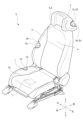
- FIG. 1 is a perspective view of a vehicle seat according to the present embodiment.
- FIG. 3 is a cross-sectional view of the headrest, showing a cushion material and a skin material. It is a perspective view of a seat frame and a blower device. It is a front view of a seat frame and a blower device.
- FIG. 3 is an exploded perspective view of a pillar, a front cover, a rear cover, and a lower cover. It is an exploded perspective view of a pillar, a front cover, a rear cover, and a lower cover seen from another angle.
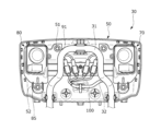
- FIG. 3 is an enlarged view of the main parts of the front cover, showing an opening.
- FIG. 1 is a diagram illustrating a method 1 for manufacturing a vehicle seat.
- 13A is a diagram showing a continuation of FIG. 13A.
- FIG. 2 is a diagram illustrating a method 2 for manufacturing a vehicle seat.
- 14A is a diagram showing a continuation of FIG. 14A.
- FIG. 14B is a figure which shows the continuation of FIG. 14B.
- the present embodiment is a vehicle seat that includes a headrest and left and right speakers provided inside the headrest, the headrest includes a speaker assembly for assembling the speakers, and the speaker assembly includes: It has left and right speaker holding parts that hold the left and right speakers in a state exposed to the front side of the seat, and a connecting part that connects the left and right speaker holding parts and is formed integrally with the left and right speaker holding parts.
- This relates to a vehicle seat whose main feature is that the Note that the side on which the seated person sits with respect to the seat back (headrest) of the vehicle seat is the front side of the seat.
- the vehicle seat S of this embodiment is a vehicle seat, and includes a seat body having a seat cushion 1, a seat back 2, and a headrest 3, and as shown in FIG.
- a blower device 4 is attached to the inside of the seat back 2 and blows air toward the seated person.
- a speaker 5 is attached to the inside of the headrest 3 and outputs sound to the seated person. It is equipped with a microphone 6 that receives sound and converts it into an electrical signal.
- the vehicle seat S also includes a control device 7 attached to the seat body, connected to the blower device 4, the speaker 5, and the microphone 6, and controlling the blower device 4, the speaker 5, and the microphone 6.
- the vehicle seat S includes a rail device that supports the seat body so as to be movable back and forth relative to the vehicle floor, a height link device that connects the seat body to the vehicle floor so as to be movable up and down, and a seat cushion 1 that is connected to the seat cushion 1.
- the vehicle may further include a reclining device that rotatably connects the seat back 2.
- the seat cushion 1 is a seating portion that supports a seated person from below, and includes a cushion frame 10 serving as a skeleton, a cushion material 1a placed on the cushion frame 10, and a cushion frame 10. and a skin material 1b that covers the cushion material 1a.
- the seat back 2 is a backrest that supports a seated person from behind, and is mainly composed of a back frame 20 serving as a skeleton, a cushion material 2a, and a skin material 2b. has been done.
- the headrest 3 is a head that supports the occupant's head from behind, and includes a headrest frame 30 serving as a skeleton, and cushioning materials 3a and 3b placed on the headrest frame 30. and skin materials 3c and 3d that cover the headrest frame 30 and cushion materials 3a and 3b.
- the cushioning material 3a is an elastic body made of an elastic material such as urethane.
- the second cushion material 3b is a three-dimensional network-like elastic body formed of three-dimensionally intertwined fibers.
- the second cushion material 3b has both the function of a cushion material and the function of transmitting the sound output from the speaker 5. Note that the second cushion material 3b may be formed to have higher acoustic transparency than the cushion material 3a, and is not limited to a three-dimensional net-like elastic body.
- the skin material 3c is a covering material made of a stretchable leather material or the like.
- the second skin material 3d is a covering material formed of three-dimensionally intertwined fibers.
- the second skin material 3d has both the function of a covering material and the function of transmitting the sound output from the speaker 5. Note that the second skin material 3d is not particularly limited as long as it has higher acoustic transparency than the skin material 3c.
- the cushion portions of the cushion material corresponding to the left and right speakers 5 and the microphone 6 in the front-rear direction of the seat serve as the second cushion material 3b.
- the rest of the cushion portion is a cushion material 3a.
- the skin portions corresponding to the left and right speakers 5 and microphones 6 in the front-rear direction of the seat are the second skin materials 3d.
- the other skin portion is the skin material 3c.
- cushion portion and the skin portion corresponding only to the speaker 5 may be the second cushion material 3b and the second skin material 3d, respectively.
- the entire cushion material and the entire skin material of the headrest 3 may be the second cushion material 3b and the second skin material 3d, respectively.
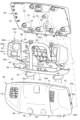
- the blower device 4 is attached to the front surface of the upper part of the back frame 20, as shown in FIGS. 3 and 4. Specifically, it is attached to the front surfaces of the connecting frame 23 and the rear frame 24 of the back frame 20 via attachment brackets 27 .
- the blower device 4 includes a blower main body 4a that supplies air, a duct 4b that allows air to pass through, and an outlet 4c that blows out air toward the back of a seated person.
- the blower main body 4a is arranged at the center of the upper part of the back frame 20.
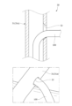
- the duct 4b extends from the blower main body 4a to the outside (right side) in the seat width direction, is bent so as to surround the pillar 31, and extends toward the front side of the seat.
- the air outlet 4c is formed at the extending end of the duct 4b.
- the blower device 4 (blower main body 4a) is connected to the control device 7 via a blower harness 4d.
- the blower harness 4d extends from the blower main body 4a to the outside (left side) in the seat width direction, is bent so as to surround the pillar 31, and extends downward.
- the speakers 5 are speaker units, and are provided inside the headrest frame 30, and are disposed on the left and right side portions of the headrest frame 30.
- the headrest frame 30 is attached to the front surface of the rear cover 50 via the speaker assembly 70 on the left and right sides.
- the microphone 6 is a microphone unit, and similarly to the speaker 5, it is arranged on the left and right side portions of the headrest frame 30, and is attached to the left and right sides via the speaker assembly 70.
- the speaker 5 and the microphone 6 are connected to the control device 7 via a speaker harness 100A and a microphone harness 100B, respectively, as shown in FIGS. 3 and 8 to 10.
- the harnesses 100A and 100B extend inward in the seat width direction from the speaker 5 and the microphone 6, respectively, and are combined into one harness 100, passing through the inside of the pillar 31 (left pillar 31) and extending downward. Details will be described later.
- the control device 7 is a device for controlling electrical components, and is attached to the bottom surface of the cushion frame 10 via a holder (not shown).
- the control device 7 is electrically connected to the blower device 4 via a blower harness 4d and a harness 100. Further, it is electrically connected to a speaker 5 and a microphone 6 via a harness 100 (harnesses 100A and 100B). Note that the control device 7 may be connected to these electrical components by wireless communication.
- the control device 7 is also connected to a battery (not shown), and controls the blower device 4, the speaker 5, and the microphone 6 to be supplied with electricity.
- the control device 7 is externally connected to, for example, an external terminal, such as a tablet terminal, a smartphone, a computer such as a PC, or an electrical device, and receives a predetermined control signal (control information). Then, the drive of the blower device 4, speaker 5, and microphone 6 is controlled based on the control signal. Note that the control device 7 may be attached to a different location inside the vehicle seat S, or may be attached to the outside of the vehicle seat S.
- the cushion frame 10 is composed of a substantially rectangular frame-like body, and includes cushion side frames arranged on the left and right sides and extending in the front-rear direction of the seat, and a front portion of each cushion side frame. It mainly consists of a pan frame to be constructed, a connecting frame that connects the rear portions of each cushion side frame, and a plurality of elastic springs that are hooked to the pan frame and the connecting frame and extend in a serpentine shape in the front and rear direction of the seat. It is configured.
- the control device 7 is attached to the bottom surface of the cushion frame 10 (pan frame).
- the back frame 20 is composed of a substantially rectangular frame-like body, and includes side frames 21 arranged on the left and right sides and extending in the vertical direction, and an upper end portion of each side frame 21.
- an inverted U-shaped upper frame 22 that connects the side frames 21, a lower frame (not shown) that connects the lower end portions of each side frame 21, and a lower portion of the left and right upper frames 22, extending in the seat width direction.
- It includes a plate-shaped connecting frame 23 and a plate-shaped rear frame 24 attached to the rear surface of the upper frame 22.
- the back frame 20 also includes left and right support wires 25 (occupant support wires) which are hooked onto the connecting frame 23 and the lower frame and extend in the vertical direction, and left and right support wires 25 (occupant support wires) which are disposed in the center of the back frame 20.
- the vehicle further includes a substantially rectangular support plate 26 (occupant support plate) that is held by the vehicle body 25 and supports the seated person from behind. Note that the left and right side frames 21, the upper frame 22, and the lower frame correspond to a "frame-shaped main body frame.”
- a mounting bracket 27 for mounting the blower device 4 is further attached to the front surfaces of the connection frame 23 and the rear frame 24.
- the central portion of the connecting frame 23 in the seat width direction has a concave shape that is concave toward the rear of the seat.
- the rear frame 24 is arranged to cover substantially the entire upper frame 22 and connection frame 23 from the rear.
- the mounting bracket 27 is attached to the front surface of the connection frame 23 from the front of the seat so as to be partially fitted therein, and is fixed to the connection frame 23 and the rear frame 24 with a plurality of fastening bolts 28 .
- the mounting bracket 27 is disposed between the left and right pillars 31 and the rear frame 24 in the front-rear direction of the seat. Further, the plurality of fastening bolts 28 are arranged so as to surround the blower device 4 (blower main body 4a) when viewed from the front of the seat. By doing so, the mounting rigidity of the blower device 4 can be increased.
- a harness holding portion 24a for holding the harness 100 is formed at the lower end of the rear frame 24. Further, a third harness attachment hole 24b (third harness attachment part) for attaching a third attachment clip 103 (third attached part) provided on the harness 100 is formed on the front surface of the harness holding part 24a. There is.
- the harness holding parts 24a hang down from the lower end of the rear frame 24, and are formed in plurality at intervals in the seat width direction. With the above configuration, the harness 100 extending from the speaker 5 and the microphone 6 can be suitably held. Further, interference between the harness 100 and other components can be suppressed.
- Left and right pillar guides 29 are assembled to the upper end of the upper frame 22 for attaching the left and right pillars 31 that serve as core members of the headrest 3.
- the pillar guide 29 is a guide member that is fixed to the back frame 20 and holds the pillar 31 movably in the vertical direction.
- the left and right pillar guides 29 are arranged at positions overlapping the mounting brackets 27 in the seat front-rear direction, and are arranged at different positions from the mounting brackets 27 in the seat width direction. Therefore, the design is such that the components are arranged in a compact manner while preventing the components from interfering with each other.
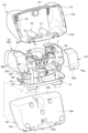
- the headrest frame 30 is assembled to an inverted U-shaped pillar 31, which is the core material of the headrest 3, and to the pillar 31, so as to sandwich the pillar 31 from the front and rear directions of the seat. It is mainly composed of a front cover 40 and a rear cover 50 which are arranged in the front cover 40 and a rear cover 50, and a lower cover 60 which is arranged so as to cover the pillar 31 from below.
- the front cover 40, the rear cover 50, and the lower cover 60 are arranged so as to cover the pillar 31, the speaker 5, the microphone 6, and the speaker assembly 70 from the outside, and are assembled with each other.
- the front cover 40, the rear cover 50, and the lower cover 60 correspond to the "main body of the headrest.”
- the pillars 31 are cylindrical support members that support the main body of the headrest 3, and are arranged at predetermined intervals in the seat width direction.
- the seat has left and right pillar extensions 31a extending downwardly toward the seat back 2, and a pillar connection part 31b connecting the upper ends of the left and right pillar extensions 31a and extending in the seat width direction. are doing.
- a harness insertion hole 32 for passing the harness 100 is formed in the outer peripheral surface of the pillar 31 (left pillar extension 31a).
- the harness insertion hole 32 is formed on the inner surface of the pillar extension part 31a in the seat width direction, and has a reverse tapered cross-sectional shape. Therefore, it is possible to easily insert the harness into the pillar. Moreover, unintentional deformation of the harness can be suppressed. Note that the cross-sectional shape of the harness insertion hole 32 may be tapered or linear.
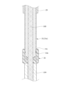
- a cylindrical cap member 33 that is more flexible than the metal pillar 31 is attached to the lower end of the pillar 31 (left pillar extension 31a).
- the cap member 33 is also called a pillar end cap, and is, for example, a rubber cap, and is attached to the lower end of the pillar 31 so as to be detachable from below.
- the cap member 33 has a support protrusion 33a formed on its inner peripheral surface and capable of being hooked into a support groove 31c provided on the outer peripheral surface of the pillar 31.
- the cap member 33 is attached to the support groove 31c by the support protrusion 33a, and is attached to cover the end surface, inner surface, and outer surface of the lower end of the pillar 31. Therefore, when the harness 100 is exposed from the lower end of the pillar 31, the harness 100 can be protected by the cap member 33.
- the front cover 40 is a cover made of resin, and is integrally assembled with the rear cover 50 and the lower cover 60. Specifically, the front cover 40 is assembled with the rear cover 50 in the seat front-rear direction, and then assembled with the lower cover 60 in the up-down direction.
- the front cover 40 is a plate body including a front wall portion 40a, a top wall portion 40b, left and right side walls 40c, and a bottom wall portion 40d.
- the front cover 40 also includes a cover center section 41 provided at the center in the seat width direction, and left and right covers that are arranged on the left and right outer sides of the cover center section 41 and protrude toward the front of the seat relative to the cover center section 41.
- a side portion 42 is provided.
- a locking piece 43 and a locking hole 43a that protrude toward the rear of the seat and can be locked to the rear cover 50 are formed at the upper end and both left and right ends.
- a first pillar latching recess 44 is formed at the upper end of the rear surface of the front cover 40, which projects toward the rear of the seat and is attachable to the rear cover 50 (first pillar latching clip 56).
- left and right second pillar latching recesses 45 that can be attached to the rear cover 50 (left and right second pillar latching clips 57) are formed at the rear end of the bottom surface of the front cover 40.
- Left and right assembly bosses 46 (assembly portions) that are recessed toward the rear of the seat and that can be assembled to the rear cover 50 (assembly hole 58) are formed in the lower part of the front surface of the front cover 40.
- the locking piece 43 (locking hole 43a) is removably locked to the locking claw 55, and the pillar locking recesses 44 and 45 are removably lockable to the pillar locking clips 56 and 57.
- the front cover 40 is permanently fixed to the rear cover 50 by bolting the assembly boss 46 into the assembly hole 58.
- An engagement hole 47 is formed in the bottom surface of the front cover 40 so as to penetrate in the vertical direction and can be assembled to the lower cover 60 (engagement hook 62).
- a fixing hole 48 (fixing portion) is formed at the lower end of the front cover 40 so as to protrude downward and is fixed to the lower cover 60 (fixing boss 63).
- the front cover 40 is temporarily fixed to the lower cover 60 by the engagement hole 47 being removably engaged with the engagement hook 62.
- the front cover 40 is integrally fixed to the lower cover 60 by bolting the fixing boss 63 in contact with the fixing hole 48 .
- the fixing boss 63 is brought into contact with the fixing hole 48 of the front cover 40 and the fixing hole 59 of the rear cover 50 in a state where they are overlapped like a tally. Thereafter, the front cover 40, rear cover 50, and lower cover 60 are permanently fixed by bolting.
- the left and right cover side portions 42 have grid-shaped openings 49 formed at positions corresponding to the left and right speakers 5 in the front-rear direction of the seat.
- the opening 49 is also called a speaker grill, and has a plurality of passage holes through which the sound output from the speaker 5 passes.
- the openings 49 are formed in a grid shape, but are not particularly limited, and may be formed in a net shape, and are not particularly limited as long as they have a shape that allows sound to pass through.
- reinforcing ribs 49a are formed along a lattice-shaped frame on the rear surface of the opening 49. As shown in FIG.
- the reinforcing ribs 49a extend in the seat width direction and the up-down direction.
- the reinforcing rib 49a extending in the seat width direction is connected to a wall portion 41a (partition wall portion) between the cover center portion 41 and the cover side portion 42.
- the rear cover 50 is a cover made of resin, and is integrally assembled with the front cover 40 and the lower cover 60.
- the rear cover 50 is assembled with the front cover 40 in the seat front-rear direction, and then is assembled with the lower cover 60 in the up-down direction.
- the rear cover 50 is a plate body including a rear wall portion 50a, a top wall portion 50b, left and right side walls 50c, and a bottom wall portion 50d.
- left and right attachment bosses 51 (attachment portions) are formed that protrude toward the front of the seat and are attachable to the speaker assembly 70 (left and right cover attachment holes 91).
- left and right second attachment bosses 52 (second attachment portions) that can be attached to the speaker assembly 70 (left and right second cover attachment holes 85) are formed at the lower end of the front surface of the rear cover 50.
- a third attachment boss 53 (third attachment portion) that can be attached to the speaker assembly 70 (third cover attachment hole 92) is formed in the center of the front surface of the rear cover 50.
- the left and right second attachment bosses 52 are arranged outside the left and right attachment bosses 51 in the seat width direction.
- the third attachment boss 53 is arranged inside the left and right attachment bosses 51.
- the speaker assembly 70 is attached to the front surface of the rear cover 50. Specifically, the speaker assembly 70 (third cover attachment hole 92) is temporarily fixed to the rear cover 50 (third attachment boss 53). Then, the cover mounting holes 91 and 85 are permanently fixed to the mounting bosses 51 and 52 using mounting bolts.
- a second harness attachment hole 54 for attaching the harness 100 is formed at the lower end of the front surface of the rear cover 50. By doing so, the harness 100 can be suitably held by the rear cover 50.
- locking claws 55 that protrude toward the front of the seat and can be locked to the front cover 40 (locking pieces 43) are formed at the upper end and both left and right ends.
- a first pillar latching clip 56 (first pillar latching portion) is formed at the upper end of the front surface of the rear cover 50 and projects toward the front of the seat and is attachable to the front cover 40 (first pillar latching recess 44).
- left and right second pillar latching clips 57 (second pillar latching portions) that can be assembled to the front cover 40 (second pillar latching recess 45) are formed at the front end of the bottom surface of the rear cover 50.
- left and right assembly holes 58 (assembled parts) that are recessed toward the rear of the seat and that can be assembled to the front cover 40 (left and right assembly bosses 46).
- the pillar retaining clip 56 is arranged at a position overlapping the left and right attachment bosses 51 in the vertical direction. As shown in FIG. 8, the pillar retaining clips 56 and 57 are arranged at positions sandwiching the left and right second attachment bosses 52 and third attachment bosses 53 in the vertical direction. The pillar retaining clip 56 is arranged between the left and right attachment bosses 51 and 52 in the seat width direction. The second pillar latching clip 57 is arranged between the left and right attachment bosses 52 in the seat width direction. The first pillar latching clip 56 is formed so as to clamp the pillar 31 in the vertical direction, and the second pillar latching clip 57 is formed so as to clamp the pillar 31 in the seat width direction.
- the pillar 31 and the front cover 40 are assembled to the front surface of the rear cover 50. More specifically, first, the pillar 31 is latched to the rear cover 50 (pillar latching clips 56, 57). The front cover 40 (locking piece 43, pillar locking recesses 44, 45) is locked to the rear cover 50 (locking claw 55, pillar locking clips 56, 57). Then, the front cover 40 (assembly boss 46) is assembled with bolts to the rear cover 50 (assembly hole 58). Note that the pillar 31 is held between the front cover 40 (pillar latching recesses 44 and 45) and the rear cover 50 (pillar latching clips 56 and 57) in the seat longitudinal direction.
- a gap filling member 34 is attached to fill the gap.
- the gap filling member 34 is a flexible (elastic) member. By interposing the gap filling member 34, it is possible to suppress rattling of the pillar 31 or the rear cover 50. Moreover, generation of abnormal noise between the pillar 31 and the rear cover 50 can be suppressed.
- the gap filling member 34 may be a nonwoven fabric, or may be a dowel, a wrinkle, or a rib formed on the outer periphery of the pillar 31 or the outer surface of the rear cover 50.
- a fixing hole 59 (fixing portion) is formed at the lower end of the rear cover 50 so as to protrude downward and is fixed to the lower cover 60 (fixing boss 63).
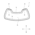
- the lower cover 60 is a cover made of resin, and is integrally assembled with the front cover 40 and the rear cover 50. arranged to cover.
- the lower cover 60 is a plate body having a downwardly curved shape. Specifically, the outer edge portion of the lower cover 60 is formed to protrude upward.
- Left and right pillar insertion holes 61 (pillar insertion portions) for passing the pillars 31 (left and right pillar extension portions 31a) through the left and right side portions of the upper surface of the lower cover 60 are formed. By doing so, the lower cover 60 can be assembled to the pillar 31 hooked to the rear cover 50.
- An engagement hook 62 is formed in the center of the upper surface of the lower cover 60 so as to protrude upward and can be detachably engaged with the front cover 40 (engagement hole 47).
- a plurality of fixing bosses 63 (fixed parts) are formed on the upper surface of the lower cover 60 so as to protrude upward and can be fixed to the front cover 40 (fixing holes 48) and the rear cover 50 (fixing holes 59).
- the fixing bosses 63 are arranged at intervals in the seat width direction so as to sandwich the engagement hook 62 therebetween.
- the speaker assembly 70 is a resin box (casing), and is provided on the left and right side portions of the headrest 3, and is attached to the left and right speakers 5.
- Left and right speaker holding parts 80 that hold the microphone 6 in a state exposed to the front side of the seat, and a connecting part 90 that connects the left and right speaker holding parts 80 and is integrally formed with the left and right speaker holding parts 80.
- “Formed as one piece” includes a state in which the speaker holding part 80 and the connecting part 90 are integrally molded, or are integrated by welding or the like. Furthermore, it includes a state in which they are assembled with each other without requiring separate mounting members (mounting plates, mounting bolts, etc.).
- the speaker assembly 70 is arranged so that the left and right speaker holding parts 80 cover the pillar 31 from both sides in the seat width direction, and the connecting part 90 covers the pillar 31 from the rear side of the seat. By doing so, for example, it is possible to suppress the speaker assembly 70 and the speaker 5 from shaking (moving) in the left-right direction and the front-back direction with respect to the headrest 3 (pillar 31) while the vehicle is running. can.
- the speaker holding section 80 has a function of accommodating the speaker 5 and the microphone 6, and a function of accommodating the harness 100 connected to the speaker 5 and the microphone 6, respectively. are doing.
- the speaker holding portion 80 includes a central wall portion 80a, a protruding wall portion (a top wall portion 80b, a bottom wall portion 80c, and a side wall portion 80d) that protrudes from the outer edge portion of the central wall portion 80a toward the front of the seat, and a central wall portion 80a. It has an extending wall portion (rear upper wall portion 80e, rear bottom wall portion 80f, left and right rear side wall portions 80g) extending rearward from the outer edge portion of the seat.
- the speaker holding portion 80 further includes a second extending wall portion (a lower front wall portion 80h, a flange wall portion 80i, and a reinforcing wall portion 80j) extending downward from the rear bottom wall portion 80f.
- the upper wall portion 80b protrudes forward from the upper end portion of the main body (center wall portion 80a) of the speaker holding portion 80.
- the bottom wall portion 80c projects forward from the lower end of the center wall portion 80a.
- the side wall portion 80d projects forward from the side end (right end) of the center wall portion 80a.
- Each front end portion is in contact with the rear surface of the front cover 40. By doing so, the front cover 40 can be suitably supported by the speaker assembly 70 when an external load is applied from the front side of the seat.
- these wall portions 80b, 80c, and 80d do not necessarily need to be in contact with the front cover 40, and may be arranged so as to be able to come into contact with the front cover 40.
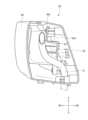
- the speaker holding part 80 is provided at the front position thereof, and has an accommodation recess 81 for accommodating the speaker 5 and the microphone 6, and is provided at the rear position of the speaker holding part 80, It has a rear accommodation recess 82 in which the harness 100 is accommodated, and a lid part 83 that covers the rear accommodation recess 82 from the rear of the seat.
- the speaker 5 and the microphone 6 are housed in the housing recess 81 from the front side of the seat, and are held in an exposed state on the front side of the seat.
- the speaker 5 is housed so as to pass through the bottom surface of the housing recess 81 and is held in a state where it is exposed from the speaker holding part 80 to the front side of the seat and the rear side of the seat.
- the microphone 6 is accommodated in a recess 81a provided on the bottom surface of the accommodation recess 81, and is held in a state where it is exposed from the speaker holding section 80 toward the front side of the seat.
- the speaker 5 penetrates the housing bottom surface of the housing recess 81 and the housing bottom surface of the rear housing recess 82 in the seat front-rear direction. In other words, the speaker 5 can be said to be housed in the housing recess 81 and the rear housing recess 82 .
- the speaker holding section 80 holds the speaker 5 in a state exposed to the front side of the seat, and also moves the microphone 6 to the front side of the seat at a position below the speaker 5. It is held in an exposed position. Further, the speaker 5 and the microphone 6 are arranged between the upper end of the attachment boss 51 and the lower end of the connecting portion 90 in the vertical direction. By doing so, the rear cover 50, the speaker assembly 70, the speaker 5, and the microphone 6 can be firmly attached to the pillar 31 serving as the core material of the headrest 3.
- a harness 100A connected to the speaker 5 and a harness 100B connected to the microphone 6 are accommodated in the rear accommodation recess 82.
- the rear housing recess 82 is covered by a lid 83 from the rear of the seat. More specifically, as shown in FIG. 6, bolt holes 82a and 83a are formed in the lower end of the rear housing recess 82 and the lower end of the lid 83, respectively.
- the lid part 83 is attached to the rear accommodation recess 82 by attaching the fixing bolt with these bolt holes 82a and 83a communicating with each other.
- each of the extending ends of the harnesses 100A and 100B protrudes inward in the seat width direction from a gap formed on the inner surface of the rear accommodation recess 82.
- a chamfered portion 84 is formed at a corner of the housing recess 81 (a corner at the inner lower end). By doing so, the rigidity of the housing recess 81 can be increased. Furthermore, interference between the housing recess 81 and other components can be suppressed.
- the lower end of the speaker holding portion 80 has left and right second cover attachment holes 85 that can be attached to the rear cover 50 (left and right second attachment bosses 52). It is formed.
- the second cover attachment hole 85 is located directly below the speaker 5 and microphone 6. Moreover, it is arranged at a position outside the pillar 31 in the seat width direction.
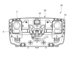
- the connecting portion 90 is a connecting bracket that is elongated in the seat width direction, and is a portion for assembling the speaker assembly 70 to the pillar 31. 5 (microphone 6).
- the connecting portion 90 includes a rear wall portion 90a that extends in the width direction of the seat and connects the left and right speaker holding portions 80, and an upper wall portion 90b that extends toward the front of the seat from the upper end of the rear wall portion 90a. It has a front wall part 90c extending upward from the front end of the upper wall part 90b.
- Left and right cover attachment holes 91 that can be attached to the rear cover 50 are formed at the upper end of the connecting portion 90 (front wall portion 90c). Further, a third cover attachment hole 92 that can be attached to the rear cover 50 (third attachment boss 53) is formed in the center of the connecting portion (rear wall portion 90a).
- Harness guide parts 93 and 94 are formed on the rear surface of the connecting part 90 (front wall part 90c) so as to protrude toward the rear of the seat and guide the harness 100.
- the harness guide section 93 and the second harness guide section 94 are arranged in a row in the seat width direction, and are arranged at a position facing the rear accommodation recess 82 .
- the harness guide parts 93 and 94 are U-shaped and support the harness 100 from above, below, and from the front after the harness 100 is attached from the rear of the seat.
- a harness attachment hole for attaching an attachment clip 101 provided on the harness 100 to support the harness 100 is provided on the front surface of the central portion of the connecting portion 90 (rear wall portion 90a).
- a plurality of 95 are formed.
- the front surfaces of the left and right side portions of the connecting portion 90 protrude toward the front of the seat toward the pillar 31 and come into contact with the rear surface of the pillar 31.
- a contact rib 97 is formed.
- a plurality of harness attachment holes 95 are arranged in a row in the seat width direction.
- the reinforcing ribs 96 extend laterally and laterally outwardly than the plurality of harness attachment holes 95 in the seat width direction, and protrude toward the opposite side (the seat rear side) from the harness 100 side (the seat front side). Therefore, when forming the reinforcing ribs 96 around the harness attachment hole 95, the reinforcing ribs can be arranged while suppressing interference between the harness 100 and the reinforcing ribs 96.
- the contact ribs 97 are formed on the left and right sides at predetermined intervals in the sheet width direction.
- the left and right contact ribs 97 are arranged so as to sandwich the harness attachment hole 95 therebetween.
- the abutting rib 97 connects the first abutting rib 97a and the second abutting rib 97b, which are arranged at intervals in the vertical direction, and the first abutting rib 97a and the second abutting rib 97b. It has a connecting rib 97c.
- the first abutting rib 97a, the second abutting rib 97b, and the connecting rib 97c are in contact with the rear surface of the pillar 31, respectively, as shown in FIG. Note that the contact rib 97 does not necessarily have to be in contact with the pillar 31, and may be arranged so as to be able to come into contact with the pillar 31.
- the harnesses 100A and 100B extend inward in the seat width direction from the speaker 5 and the microphone 6, respectively, and are combined into one harness 100, ) and extends downward toward the seat back 2. It further extends from the seat back 2 toward the seat cushion 1 and is connected to a control device 7 provided on the seat cushion 1.
- Harnesses 100A and 100B each have an attachment clip 101 that can be attached to speaker assembly 70 (harness attachment hole 95). Specifically, it has a coupler at a position facing the harness attachment hole 95, and has an attachment clip 101 provided on the coupler. Further, the harness 100 has a second attachment clip 102 that can be attached to the rear cover 50 (second harness attachment hole 54). Further, the harness 100 has a third attachment clip 103 that is provided inside the seat back 2 and that can be attached to the rear frame 24 (third harness attachment hole 24b). Further, the harness 100 includes a harness guide 104 that is provided inside the seat back 2 and covers the harness 100 (harness main body).
- the harness 100A (100B) is connected to the speaker 5 (microphone 6) and is accommodated in the rear accommodation recess 82.
- a harness 100A extending from the speaker 5 extends inward in the seat width direction from the rear accommodation recess 82 and is supported by harness guide parts 93 and 94.
- the harness 100A extends downward from the harness guide portions 93 and 94 and is supported by the harness attachment hole 95.
- the attachment clip 101 is attached to the harness attachment hole 95.
- the harness 100A and the harness 100B extend downward and are combined into one harness 100.
- the combined harness 100 is supported by the second harness attachment hole 54.
- the second attachment clip 102 is attached to the rear cover 50 (second harness attachment hole 54).
- the harness 100 extends from the second harness attachment hole 54 toward one side (left side) in the seat width direction toward the pillar 31 (left pillar extension 31a).
- the harness 100 is passed into the pillar 31 through a harness insertion hole 32 provided in the pillar 31, and extends downward toward the seat back.
- the harness 100 and the blower harness 4d are combined into one and extend downward toward the seat cushion 1.
- the combined harness 100 is connected to a control device 7 provided inside the seat cushion 1.
- harnesses 100A and 100B extend from the speaker 5 and microphone 6, respectively. It may be devised to prevent these harnesses 100A and 100B from being assembled incorrectly.
- the thickness of the harness 100A connected to the speaker 5 and the thickness of the harness 100B connected to the microphone 6 may be changed. That is, the thickness of the harness 100A may be made thicker than the thickness of the harness 100B. Or you can make it thinner.
- the coupler (connector) of the harness 100A and the coupler (connector) of the harness 100B may have different shapes, different sizes, different colors, and different marks. As another mark, the mark “S (Speaker)" may be given to the harness 100A, and the mark “M (Microfone)” may be given to the harness 100B.
- the left and right harnesses 100 are combined into one and passed through the left pillar 31.
- the harness 100 connected to the left speaker 5 extends from the left speaker toward the pillar 31, and is inserted into the pillar 31 through the harness insertion hole 32 provided in the left pillar extension 31a. It may be passed through the inside of.
- the harness 100 connected to the right speaker 5 may be passed into the pillar 31 through the harness insertion hole 32 provided in the right pillar extension 31a.
- cover attachment holes 91, 85, and 92 are attached to the left and right attachment bosses 51, 52, and 53. More specifically, the cover mounting holes 91 and 85 are bolted to the mounting bosses 51 and 52. Note that the third cover attachment hole 92 is hooked onto the third attachment boss 53 to temporarily fix it. Then, the pillar 31 is latched onto the rear cover 50. Specifically, the pillar 31 is latched to the pillar latching clips 56 and 57. Then, the harness 100 is passed through the inside of the pillar 31. Then, the front cover 40 is assembled to the rear cover 50, and the lower cover 60 is assembled from below with the front cover 40 and the rear cover 50 assembled.
- the speaker 5 and the microphone 6 are assembled to the speaker assembly 70.
- the speaker assembly 70 is "temporarily fixed” to the rear cover 50.
- the third cover attachment hole 92 is hooked onto the third attachment boss 53 for temporary fixation.
- the pillar 31 is latched onto the rear cover 50.
- the speaker assembly 70 is pressed against the rear cover 50 by the pillar 31.
- the speaker assembly 70 is "finally fixed” to the rear cover 50.
- the cover mounting holes 91 and 85 are bolted to the mounting bosses 51 and 52.
- the harness 100 is passed through the inside of the pillar 31.
- the front cover 40 is assembled to the rear cover 50, and the lower cover 60 is assembled from below with the front cover 40 and the rear cover 50 assembled.
- the headrest frame 30 includes a front cover 40, a rear cover 50, and a lower cover 60, but this is not particularly limited.
- the lower cover 60 may be unnecessary.
- the front cover 40 or the rear cover 50 may be unnecessary.
- the engagement hole 47 of the front cover 40 and the engagement hook 62 of the lower cover 60 engage with each other, but the engagement structure is not particularly limited. It's not something you can do.
- the engagement hole 47 may be replaced with an engagement recess.
- an engagement structure other than an engagement hole and an engagement hook may be used. That is, the engaged portion of the front cover 40 and the engaging portion of the lower cover 60 may be engaged with each other using other engagement structures.
- the structure of the locking part and the locked part, the structure of the attaching part and the attached part, the structure of the assembly part and the assembled part, the structure of the fixing part and the fixed part, etc. may be changed as appropriate. Also good.
- the left and right speaker holding parts 80 and the connecting part 90 are integrally formed in the speaker assembly 70, but this is not particularly limited.
- the left and right speaker holding parts 80 and the connecting part 90 may be formed separately. That is, the speaker holding part 80 and the connecting part 90 may be connected via an attachment member.
- the speaker holding part 80 has the housing recess 81 and the rear housing recess 82, but it may have either one of the housing recesses.
- the speaker holding portion 80 may have only the rear accommodation recess 82 (accommodation recess), and may accommodate the speaker 5, the microphone 6, and the harness 100.
- the speaker 5 and the microphone 6 are preferably disposed so as to pass through the housing bottom surface of the rear housing recess 82 and be exposed to the front side of the seat.
- a vehicle seat used in a car was described as a specific example, but there is no particular limitation, and the seat can also be used as a seat for vehicles such as trains and buses, as well as seats for vehicles such as airplanes and ships. be able to.
- the vehicle seat according to the present invention has been mainly described.
- the embodiments described above are merely examples for facilitating understanding of the present invention, and do not limit the present invention.
- the present invention may be modified and improved without departing from its spirit, and it goes without saying that the present invention includes equivalents thereof.
Landscapes
- Engineering & Computer Science (AREA)
- Mechanical Engineering (AREA)
- Physics & Mathematics (AREA)
- Acoustics & Sound (AREA)
- Signal Processing (AREA)
- Aviation & Aerospace Engineering (AREA)
- Transportation (AREA)
- Seats For Vehicles (AREA)
- Fittings On The Vehicle Exterior For Carrying Loads, And Devices For Holding Or Mounting Articles (AREA)
Abstract
ヘッドレストに対しスピーカを容易に組み付けることが可能な乗り物用シートを提供する。 乗り物用シートは、ヘッドレスト(3)と、ヘッドレスト(3)の内部に設けられる左右のスピーカ(5)とを備えている。ヘッドレスト(3)は、その内部に設けられ、スピーカ(5)を組み付けるためのスピーカ組み付け体(70)を備えている。スピーカ組み付け体(70)は、ヘッドレスト(3)の左右側方部分に設けられ、左右のスピーカ(5)をそれぞれシート前方側に露出させた状態で保持する左右のスピーカ保持部(80)と、左右のスピーカ保持部(80)を連結し、左右のスピーカ保持部(80)と一体に形成される連結部(90)と、を有している。
Description
本発明は、乗り物用シートに係り、特に、ヘッドレストと、ヘッドレストの内部に設けられるスピーカと、を備えた乗り物用シートに関する。
従来、ヘッドレストの内部にスピーカ(音響装置)を搭載した乗り物用シートが知られている。
例えば、特許文献1には、左右のスピーカと、左右のスピーカを組み付けるためのスピーカ組み付け体と、を備えたヘッドレストが開示されている。
上記スピーカ組み付け体は、左右のスピーカをそれぞれシート前方側に露出させた状態で保持する左右のスピーカ保持部(エンクロージャー)と、左右のスピーカ保持部を連結する連結部(連結板)と、を有している。左右のスピーカ保持部は、組み付けボルトによって連結部に組み付けられている。また、スピーカ組み付け体は、ヘッドレスト(ヘッドレストピラー)に取付板を介して取り付けられている。
例えば、特許文献1には、左右のスピーカと、左右のスピーカを組み付けるためのスピーカ組み付け体と、を備えたヘッドレストが開示されている。
上記スピーカ組み付け体は、左右のスピーカをそれぞれシート前方側に露出させた状態で保持する左右のスピーカ保持部(エンクロージャー)と、左右のスピーカ保持部を連結する連結部(連結板)と、を有している。左右のスピーカ保持部は、組み付けボルトによって連結部に組み付けられている。また、スピーカ組み付け体は、ヘッドレスト(ヘッドレストピラー)に取付板を介して取り付けられている。
ところで、特許文献1のようなスピーカを搭載したヘッドレストにおいては、ヘッドレストの構造が複雑になることから、ヘッドレスト(ヘッドレストピラー)に対しスピーカ及びスピーカ組み付け体をより容易に組み付けられることが求められていた。また、スピーカ組み付け体の構成をよりシンプルにすることが求められていた。
本発明は、上記の課題に鑑みてなされたものであり、本発明の目的は、ヘッドレストに対しスピーカを従来よりも容易に組み付けることが可能な乗り物用シートを提供することにある。
また、本発明の他の目的は、スピーカを組み付けるためのスピーカ組み付け体の構成を従来よりもシンプルにすることが可能な乗り物用シートを提供することにある。
また、本発明の他の目的は、スピーカを組み付けるためのスピーカ組み付け体の構成を従来よりもシンプルにすることが可能な乗り物用シートを提供することにある。
前記課題は、本発明の乗り物用シートによれば、ヘッドレストと、前記ヘッドレストの内部に設けられる左右のスピーカと、を備えた乗り物用シートであって、前記ヘッドレストの内部に設けられ、前記スピーカを組み付けるためのスピーカ組み付け体を備え、前記スピーカ組み付け体は、前記ヘッドレストの左右側方部分に設けられ、左右の前記スピーカをそれぞれ保持する左右のスピーカ保持部と、左右の前記スピーカ保持部を連結し、左右の前記スピーカ保持部と一体に形成される連結部と、を有していること、により解決される。
上記構成により、ヘッドレストに対しスピーカを従来よりも容易に組み付けることが可能な乗り物用シートを実現できる。
詳しく述べると、スピーカ組み付け体が、左右のスピーカ保持部と、左右のスピーカ保持部を連結し、当該スピーカ保持部と一体に形成される連結部とを有している。そのため、従来のように組み付けボルトや組み付け板を必要とせず、スピーカ組み付け体の構成を従来よりもシンプルにすることができる。またスピーカ組み付け体の部品点数を削減することもできる。つまり、ヘッドレストに対しスピーカを従来よりも容易に組み付けることができる。
上記構成により、ヘッドレストに対しスピーカを従来よりも容易に組み付けることが可能な乗り物用シートを実現できる。
詳しく述べると、スピーカ組み付け体が、左右のスピーカ保持部と、左右のスピーカ保持部を連結し、当該スピーカ保持部と一体に形成される連結部とを有している。そのため、従来のように組み付けボルトや組み付け板を必要とせず、スピーカ組み付け体の構成を従来よりもシンプルにすることができる。またスピーカ組み付け体の部品点数を削減することもできる。つまり、ヘッドレストに対しスピーカを従来よりも容易に組み付けることができる。
このとき、前記スピーカ保持部は、前記スピーカを収容させるための収容凹部を有し、前記スピーカは、前記収容凹部にシート前後方向から収容され、シート前方側に露出させた状態で保持されると良い。
上記構成により、シンプルな構成でスピーカ保持部(収容凹部)に対しスピーカをシート前方側に露出させた状態で収容することができる。
また上記のように、スピーカが収容凹部に収容されることで、例えばスピーカを外部の衝撃から好適に保護することができる。
上記構成により、シンプルな構成でスピーカ保持部(収容凹部)に対しスピーカをシート前方側に露出させた状態で収容することができる。
また上記のように、スピーカが収容凹部に収容されることで、例えばスピーカを外部の衝撃から好適に保護することができる。
このとき、前記スピーカは、前記収容凹部の収容底面を貫通するように収容され、前記スピーカ保持部からシート前方側及びシート後方側に露出させた状態で保持されると良い。
上記構成により、スピーカ保持部(収容凹部)にスピーカを好適に保持させて収容することができる。また、スピーカの組み付け状態をシート前方及びシート後方から目視確認することができる。
上記構成により、スピーカ保持部(収容凹部)にスピーカを好適に保持させて収容することができる。また、スピーカの組み付け状態をシート前方及びシート後方から目視確認することができる。
このとき、前記乗り物用シートは、前記スピーカに接続されるハーネスをさらに備え、前記スピーカ保持部は、前記スピーカ保持部の前方位置に設けられ、前記スピーカを収容させる前記収容凹部と、前記スピーカ保持部の後方位置に設けられ、前記ハーネスを収容させる後方収容凹部と、前記後方収容凹部をシート後方から覆う蓋部と、を有し、前記スピーカは、シート前後方向において前記収容凹部の収容底面と、前記後方収容凹部の収容底面とを貫通し、前記スピーカ保持部からシート前方側及びシート後方側に露出させた状態で保持されると良い。
上記構成により、スピーカ保持部に対しスピーカをシート前方から収容し、ハーネスをシート後方から収容することができる。
また上記構成により、ハーネスを収容させる後方収容凹部が蓋部によって覆われるため、後方収容凹部内に意図せず異物が混入することを抑制することができる。すなわち、スピーカやハーネスを好適に保護することができる。
上記構成により、スピーカ保持部に対しスピーカをシート前方から収容し、ハーネスをシート後方から収容することができる。
また上記構成により、ハーネスを収容させる後方収容凹部が蓋部によって覆われるため、後方収容凹部内に意図せず異物が混入することを抑制することができる。すなわち、スピーカやハーネスを好適に保護することができる。
このとき、前記ヘッドレストは、前記ヘッドレストの本体を支持するピラーと、前記ピラーに組み付けられ、前記ピラー及び前記スピーカ組み付け体をシート後方から覆うように配置される後方カバーと、をさらに備え、前記後方カバーは、前記ピラーに掛け止めるためのピラー掛け止め部と、前記スピーカ組み付け体を取り付けるための左右の取り付け部と、を有し、前記ピラー掛け止め部は、シート幅方向において左右の前記取り付け部の間に配置されていると良い。
また、前記ピラー掛け止め部は、上下方向において左右の前記取り付け部と重なる位置に配置され、前記スピーカは、上下方向において前記取り付け部の上端部と、前記連結部の下端部との間に配置されていると良い。
上記構成により、ヘッドレストの芯材となるピラー(ヘッドレストピラー)に対し後方カバー、スピーカ組み付け体及びスピーカを強固に取り付けることができる。
また、前記ピラー掛け止め部は、上下方向において左右の前記取り付け部と重なる位置に配置され、前記スピーカは、上下方向において前記取り付け部の上端部と、前記連結部の下端部との間に配置されていると良い。
上記構成により、ヘッドレストの芯材となるピラー(ヘッドレストピラー)に対し後方カバー、スピーカ組み付け体及びスピーカを強固に取り付けることができる。
このとき、前記ヘッドレストは、該ヘッドレストの本体を支持するピラーを備え、前記スピーカ組み付け体は、左右の前記スピーカ保持部よって前記ピラーをシート幅方向の両側から覆い、かつ、前記連結部によって前記ピラーをシート後方側から覆うように配置されていると良い。
上記構成により、ヘッドレストのピラーに対しスピーカ組み付け体をより強固に取り付けることができる。
また上記のように、スピーカ組み付け体がピラーをシート幅方向の両側及びシート後方側から囲むように配置されている。そうすることで、例えば乗り物の走行中に、ヘッドレスト(ピヘッドレストピラー)に対してスピーカ組み付け体及びスピーカが左右方向及び前後方向に揺れてしまう(移動してしまう)ことを抑制できる。
上記構成により、ヘッドレストのピラーに対しスピーカ組み付け体をより強固に取り付けることができる。
また上記のように、スピーカ組み付け体がピラーをシート幅方向の両側及びシート後方側から囲むように配置されている。そうすることで、例えば乗り物の走行中に、ヘッドレスト(ピヘッドレストピラー)に対してスピーカ組み付け体及びスピーカが左右方向及び前後方向に揺れてしまう(移動してしまう)ことを抑制できる。
このとき、前記ヘッドレストは、前記ヘッドレストの本体を支持するピラーと、前記ピラーに組み付けられ、前記ピラー及び前記スピーカ組み付け体をシート前方から覆うように配置される前方カバーと、をさらに備え、前記スピーカ保持部の前端部が、前記前方カバーに向かって突出し、前記前方カバーの後面に当接している又は当接可能に配置されていると良い。
また、前記スピーカ保持部は、該スピーカ保持部の本体の外縁部分からシート前方に突出する突出壁部を有し、前記突出壁部は、前記スピーカ保持部の本体の上端部から突出する上壁部と、前記スピーカ保持部の本体の下端部から突出する底壁部と、を有し、それぞれの前端部が、前記前方カバーの後面に当接している又は当接可能に配置されていると良い。
上記構成により、前方カバー及びスピーカ組み付け体の組み付け強度を高めることができる。また、シート前方側から外部荷重が加わったときに、スピーカ組み付け体によって前方カバーを好適に支持することができる。
また、前記スピーカ保持部は、該スピーカ保持部の本体の外縁部分からシート前方に突出する突出壁部を有し、前記突出壁部は、前記スピーカ保持部の本体の上端部から突出する上壁部と、前記スピーカ保持部の本体の下端部から突出する底壁部と、を有し、それぞれの前端部が、前記前方カバーの後面に当接している又は当接可能に配置されていると良い。
上記構成により、前方カバー及びスピーカ組み付け体の組み付け強度を高めることができる。また、シート前方側から外部荷重が加わったときに、スピーカ組み付け体によって前方カバーを好適に支持することができる。
このとき、前記乗り物用シートは、前記ヘッドレストの内部に設けられる左右のマイクをさらに備え、前記スピーカ保持部は、前記スピーカをシート前方側に露出させた状態で保持し、かつ、前記スピーカとは異なる位置において前記マイクをシート前方側に露出させた状態で保持すると良い。
上記構成により、ヘッドレスト(スピーカ組み付け体)に対しスピーカ及びマイクを従来よりも容易に組み付けることができる。また、スピーカ組み付け体の部品点数を増やすことなく、ヘッドレストの内部にスピーカ及びマイクを搭載することができる。
上記構成により、ヘッドレスト(スピーカ組み付け体)に対しスピーカ及びマイクを従来よりも容易に組み付けることができる。また、スピーカ組み付け体の部品点数を増やすことなく、ヘッドレストの内部にスピーカ及びマイクを搭載することができる。
本発明によれば、ヘッドレストに対しスピーカを従来よりも容易に組み付けることが可能な乗り物用シートを実現できる。また、スピーカ組み付け体の構成を従来よりもシンプルにすることができる。
また本発明によれば、シンプルな構成でスピーカ保持部(収容凹部)に対しスピーカをシート前方側に露出させた状態で収容することができる。また、例えばスピーカを外部の衝撃から好適に保護することができる。また、スピーカの組み付け状態をシート前方及びシート後方から目視確認することができる。
また本発明によれば、スピーカ保持部に対しスピーカをシート前方から収容し、ハーネスをシート後方から収容することができる。また、上記構成により、スピーカやハーネスを好適に保護することができる。
また本発明によれば、ヘッドレストの芯材となるピラーに対し後方カバー、スピーカ組み付け体及びスピーカを強固に取り付けることができる。
また本発明によれば、例えば乗り物の走行中に、ヘッドレスト(ピラー)に対してスピーカ組み付け体及びスピーカが左右方向及び前後方向に揺れてしまうことを抑制できる。
また本発明によれば、前方カバー及びスピーカ組み付け体の組み付け強度を高めることができる。
また本発明によれば、ヘッドレスト(スピーカ組み付け体)に対しスピーカ及びマイクを従来よりも容易に組み付けることができる。
以下、本発明に係る実施形態について、図1~図14Cを参照して説明する。
本実施形態は、ヘッドレストと、ヘッドレストの内部に設けられる左右のスピーカとを備えた乗り物用シートであって、ヘッドレストが、スピーカを組み付けるためのスピーカ組み付け体を備えており、当該スピーカ組み付け体が、左右のスピーカをそれぞれシート前方側に露出させた状態で保持する左右のスピーカ保持部と、左右のスピーカ保持部を連結し、左右のスピーカ保持部と一体に形成される連結部とを有していることを主な特徴とする乗り物用シートに関するものである。
なお、乗り物用シートのシートバック(ヘッドレスト)に対して着座者が着座する側がシート前方側となる。
本実施形態は、ヘッドレストと、ヘッドレストの内部に設けられる左右のスピーカとを備えた乗り物用シートであって、ヘッドレストが、スピーカを組み付けるためのスピーカ組み付け体を備えており、当該スピーカ組み付け体が、左右のスピーカをそれぞれシート前方側に露出させた状態で保持する左右のスピーカ保持部と、左右のスピーカ保持部を連結し、左右のスピーカ保持部と一体に形成される連結部とを有していることを主な特徴とする乗り物用シートに関するものである。
なお、乗り物用シートのシートバック(ヘッドレスト)に対して着座者が着座する側がシート前方側となる。
本実施形態の乗り物用シートSは、図1に示すように、車両用シートであって、シートクッション1と、シートバック2と、ヘッドレスト3とを有するシート本体と、図3に示すように、シートバック2の内部に取り付けられ、着座者に向けて空気を吹き出すブロア装置4と、ヘッドレスト3の内部にそれぞれ取り付けられ、着座者に向けて音を出力するスピーカ5と、着座者又は外部からの音を受信して電気信号に変換するマイク6と、を備えている。
また、乗り物用シートSは、シート本体に取り付けられ、ブロア装置4、スピーカ5及びマイク6と接続され、ブロア装置4、スピーカ5及びマイク6を制御する制御装置7を備えている。
そのほか、乗り物用シートSは、車体フロアに対してシート本体を前後移動可能に支持するレール装置と、車体フロアに対してシート本体を昇降可能に連結するハイトリンク装置と、シートクッション1に対してシートバック2を回動可能に連結するリクライニング装置と、をさらに備えていても良い。
また、乗り物用シートSは、シート本体に取り付けられ、ブロア装置4、スピーカ5及びマイク6と接続され、ブロア装置4、スピーカ5及びマイク6を制御する制御装置7を備えている。
そのほか、乗り物用シートSは、車体フロアに対してシート本体を前後移動可能に支持するレール装置と、車体フロアに対してシート本体を昇降可能に連結するハイトリンク装置と、シートクッション1に対してシートバック2を回動可能に連結するリクライニング装置と、をさらに備えていても良い。
シートクッション1は、図1に示すように、着座者を下方から支持する着座部であって、骨格となるクッションフレーム10と、クッションフレーム10上に載置されるクッション材1aと、クッションフレーム10及びクッション材1aを被覆する表皮材1bと、から主に構成されている。
シートバック2は、図1、図3に示すように、着座者を後方から支持する背もたれ部であって、骨格となるバックフレーム20と、クッション材2aと、表皮材2bと、から主に構成されている。
シートバック2は、図1、図3に示すように、着座者を後方から支持する背もたれ部であって、骨格となるバックフレーム20と、クッション材2aと、表皮材2bと、から主に構成されている。
ヘッドレスト3は、図1~図3に示すように、乗員の頭を後方から支持する頭部であって、骨格となるヘッドレストフレーム30と、ヘッドレストフレーム30上に載置されるクッション材3a、3bと、ヘッドレストフレーム30及びクッション材3a、3bを被覆する表皮材3c、3dと、から主に構成されている。
クッション材3aは、図2に示すように、ウレタン等の弾性材料から形成された弾性体である。
第2クッション材3bは、三次元状に絡み合う繊維により形成された立体網状の弾性体である。第2クッション材3bは、クッション材としての機能と、スピーカ5から出力される音を透過させる機能と、を兼ね備えている。
なお、第2クッション材3bは、クッション材3aよりも音響透過性が高く形成されていれば良く、立体網状の弾性体に限定されるものではない。
クッション材3aは、図2に示すように、ウレタン等の弾性材料から形成された弾性体である。
第2クッション材3bは、三次元状に絡み合う繊維により形成された立体網状の弾性体である。第2クッション材3bは、クッション材としての機能と、スピーカ5から出力される音を透過させる機能と、を兼ね備えている。
なお、第2クッション材3bは、クッション材3aよりも音響透過性が高く形成されていれば良く、立体網状の弾性体に限定されるものではない。
表皮材3cは、図2に示すように、伸縮性を有する皮革材料等から形成された被覆材である。
第2表皮材3dは、三次元状に絡み合う繊維により形成された被覆材である。第2表皮材3dは、被覆材としての機能と、スピーカ5から出力される音を透過させる機能と、を兼ね備えている。
なお、第2表皮材3dは、表皮材3cよりも音響透過性が高く形成されていれば良く、特に限定されるものではない。
第2表皮材3dは、三次元状に絡み合う繊維により形成された被覆材である。第2表皮材3dは、被覆材としての機能と、スピーカ5から出力される音を透過させる機能と、を兼ね備えている。
なお、第2表皮材3dは、表皮材3cよりも音響透過性が高く形成されていれば良く、特に限定されるものではない。
上記構成において、図2に示すように、クッション材のうち、シート前後方向において左右のスピーカ5、マイク6に対応するクッション部分が、第2クッション材3bとなっている。それ以外のクッション部分がクッション材3aとなっている。
また、表皮材のうち、シート前後方向において左右のスピーカ5、マイク6に対応する表皮部分が、第2表皮材3dとなっている。それ以外の表皮部分が表皮材3cとなっている。
そうすることで、スピーカ5から発生する音をより効率良く外部に伝えることができる。また、着座者の頭部がヘッドレスト3に接触したときに、着座者に違和感を与えてしまうことを抑制できる。
なお、スピーカ5のみに対応するクッション部分、表皮部分が、それぞれ第2クッション材3b、第2表皮材3dとなっていても良い。
あるいは、ヘッドレスト3のクッション材全体、表皮材全体が、それぞれ第2クッション材3b、第2表皮材3dとなっていても良い。
また、表皮材のうち、シート前後方向において左右のスピーカ5、マイク6に対応する表皮部分が、第2表皮材3dとなっている。それ以外の表皮部分が表皮材3cとなっている。
そうすることで、スピーカ5から発生する音をより効率良く外部に伝えることができる。また、着座者の頭部がヘッドレスト3に接触したときに、着座者に違和感を与えてしまうことを抑制できる。
なお、スピーカ5のみに対応するクッション部分、表皮部分が、それぞれ第2クッション材3b、第2表皮材3dとなっていても良い。
あるいは、ヘッドレスト3のクッション材全体、表皮材全体が、それぞれ第2クッション材3b、第2表皮材3dとなっていても良い。
<ブロア装置、スピーカ、マイク、制御装置>
ブロア装置4は、図3、図4に示すように、バックフレーム20の上方部分の前面に取り付けられている。具体的には、バックフレーム20のうち、連結フレーム23及び後方フレーム24の前面に取り付けブラケット27を介して取り付けられている。
ブロア装置4は、空気を供給するブロア本体4aと、空気を通過させるダクト4bと、着座者の背中に向けて空気を吹き出す吹き出し口4cと、を有している。
ブロア装置4は、図3、図4に示すように、バックフレーム20の上方部分の前面に取り付けられている。具体的には、バックフレーム20のうち、連結フレーム23及び後方フレーム24の前面に取り付けブラケット27を介して取り付けられている。
ブロア装置4は、空気を供給するブロア本体4aと、空気を通過させるダクト4bと、着座者の背中に向けて空気を吹き出す吹き出し口4cと、を有している。
ブロア本体4aは、バックフレーム20の上方部分の中央位置に配置されている。
ダクト4bは、ブロア本体4aからシート幅方向の外側(右側)に延びて、ピラー31を取り囲むように屈曲し、シート前方側に延びている。
吹き出し口4cは、ダクト4bの延出端部に形成されている。
なお、ブロア装置4(ブロア本体4a)は、ブロア用ハーネス4dを介して制御装置7と接続されている。ブロア用ハーネス4dは、ブロア本体4aからシート幅方向の外側(左側)に延びて、ピラー31を取り囲むように屈曲し、下方に延びている。
ダクト4bは、ブロア本体4aからシート幅方向の外側(右側)に延びて、ピラー31を取り囲むように屈曲し、シート前方側に延びている。
吹き出し口4cは、ダクト4bの延出端部に形成されている。
なお、ブロア装置4(ブロア本体4a)は、ブロア用ハーネス4dを介して制御装置7と接続されている。ブロア用ハーネス4dは、ブロア本体4aからシート幅方向の外側(左側)に延びて、ピラー31を取り囲むように屈曲し、下方に延びている。
スピーカ5は、図3、図5に示すように、スピーカユニットであって、ヘッドレストフレーム30の内部に設けられ、ヘッドレストフレーム30の左右側方部分に配置されている。具体的には、ヘッドレストフレーム30のうち、後方カバー50の前面にスピーカ組み付け体70を介して左右に取り付けられている。
マイク6は、マイクユニットであって、スピーカ5と同様にヘッドレストフレーム30の左右側方部分に配置され、スピーカ組み付け体70を介して左右に取り付けられている。
マイク6は、マイクユニットであって、スピーカ5と同様にヘッドレストフレーム30の左右側方部分に配置され、スピーカ組み付け体70を介して左右に取り付けられている。
スピーカ5、マイク6は、図3、図8~図10に示すように、それぞれスピーカ用のハーネス100A、マイク用のハーネス100Bを介して制御装置7と接続されている。
ハーネス100A、100Bは、それぞれスピーカ5、マイク6からシート幅方向の内側に延びて1本のハーネス100にまとめられ、ピラー31(左側のピラー31)の内部を通過して下方に延びている。詳細は後述する。
ハーネス100A、100Bは、それぞれスピーカ5、マイク6からシート幅方向の内側に延びて1本のハーネス100にまとめられ、ピラー31(左側のピラー31)の内部を通過して下方に延びている。詳細は後述する。
制御装置7は、図1に示すように、電装部品を制御する装置であって、クッションフレーム10の底面に不図示のホルダーを介して取り付けられている。
制御装置7は、ブロア装置4とブロア用ハーネス4d及びハーネス100を介して電気的に接続されている。また、スピーカ5、マイク6とハーネス100(ハーネス100A、100B)を介して電気的に接続されている。なお、制御装置7は、これら電装部品と無線通信で接続されていても良い。
また、制御装置7は、不図示のバッテリーとも接続されており、ブロア装置4、スピーカ5、マイク6に電気を供給するように制御する。
制御装置7は、ブロア装置4とブロア用ハーネス4d及びハーネス100を介して電気的に接続されている。また、スピーカ5、マイク6とハーネス100(ハーネス100A、100B)を介して電気的に接続されている。なお、制御装置7は、これら電装部品と無線通信で接続されていても良い。
また、制御装置7は、不図示のバッテリーとも接続されており、ブロア装置4、スピーカ5、マイク6に電気を供給するように制御する。
制御装置7は、例えば、外部の端末、例えばタブレット端末、スマートフォン、PC等のコンピュータ、電気機器と外部接続され、所定の制御信号(制御情報)を受信する。そして、当該制御信号に基づいてブロア装置4、スピーカ5及びマイク6の駆動を制御する。
なお、制御装置7は、乗り物用シートSの内部において別の箇所に取り付けられても良いし、乗り物用シートSの外部に取り付けられても良い。
なお、制御装置7は、乗り物用シートSの内部において別の箇所に取り付けられても良いし、乗り物用シートSの外部に取り付けられても良い。
<シートフレーム>
クッションフレーム10は、図示を省略しているところ、略矩形状の枠状体からなり、左右側方に配置され、シート前後方向に延びているクッションサイドフレームと、各クッションサイドフレームの前方部分に架設されるパンフレームと、各クッションサイドフレームの後方部分を連結する連結フレームと、パンフレーム及び連結フレームに掛け止めされ、シート前後方向に蛇状に延びている複数の弾性バネと、から主に構成されている。
なお、本実施形態では、クッションフレーム10(パンフレーム)の底面に制御装置7が取り付けられている。
クッションフレーム10は、図示を省略しているところ、略矩形状の枠状体からなり、左右側方に配置され、シート前後方向に延びているクッションサイドフレームと、各クッションサイドフレームの前方部分に架設されるパンフレームと、各クッションサイドフレームの後方部分を連結する連結フレームと、パンフレーム及び連結フレームに掛け止めされ、シート前後方向に蛇状に延びている複数の弾性バネと、から主に構成されている。
なお、本実施形態では、クッションフレーム10(パンフレーム)の底面に制御装置7が取り付けられている。
バックフレーム20は、図3、図4に示すように、略矩形状の枠状体からなり、左右側方に配置され、上下方向に延びているサイドフレーム21と、各サイドフレーム21の上端部分を連結する逆U字形状の上部フレーム22と、各サイドフレーム21の下端部分を連結する不図示の下部フレームと、上部フレーム22の左右の下方部分に架け渡され、シート幅方向に延びている板状の連結フレーム23と、上部フレーム22の後面に取り付けられるプレート状の後方フレーム24と、を備えている。
また、バックフレーム20は、連結フレーム23及び下部フレームに掛け止めされ、上下方向に延びている左右の支持ワイヤ25(乗員支持ワイヤ)と、バックフレーム20の中央部に配置され、左右の支持ワイヤ25によって保持され、着座者を後方から支持する略矩形状の支持プレート26(乗員支持プレート)と、をさらに備えている。
なお、左右のサイドフレーム21、上部フレーム22及び下部フレームが「枠状の本体フレーム」に相当する。
また、バックフレーム20は、連結フレーム23及び下部フレームに掛け止めされ、上下方向に延びている左右の支持ワイヤ25(乗員支持ワイヤ)と、バックフレーム20の中央部に配置され、左右の支持ワイヤ25によって保持され、着座者を後方から支持する略矩形状の支持プレート26(乗員支持プレート)と、をさらに備えている。
なお、左右のサイドフレーム21、上部フレーム22及び下部フレームが「枠状の本体フレーム」に相当する。
連結フレーム23及び後方フレーム24の前面には、ブロア装置4を取り付けるための取り付けブラケット27がさらに取り付けられている。
詳しく述べると、連結フレーム23のシート幅方向の中央部分は、シート後方に窪んだ窪み形状を有している。後方フレーム24は、上部フレーム22及び連結フレーム23の略全体を後方から覆うように配置されている。
そして、取り付けブラケット27は、シート前方から連結フレーム23の前面に一部嵌め込まれた状態で取り付けられ、かつ、連結フレーム23及び後方フレーム24に複数の締結ボルト28によって固定されている。
詳しく述べると、連結フレーム23のシート幅方向の中央部分は、シート後方に窪んだ窪み形状を有している。後方フレーム24は、上部フレーム22及び連結フレーム23の略全体を後方から覆うように配置されている。
そして、取り付けブラケット27は、シート前方から連結フレーム23の前面に一部嵌め込まれた状態で取り付けられ、かつ、連結フレーム23及び後方フレーム24に複数の締結ボルト28によって固定されている。
取り付けブラケット27は、シート前後方向において左右のピラー31と後方フレーム24の間に挟まれて配置されている。
また、複数の締結ボルト28は、シート前方から見てブロア装置4(ブロア本体4a)を囲むように配置されている。
そうすることで、ブロア装置4の取り付け剛性を高めることができる。
また、複数の締結ボルト28は、シート前方から見てブロア装置4(ブロア本体4a)を囲むように配置されている。
そうすることで、ブロア装置4の取り付け剛性を高めることができる。
後方フレーム24の下端部には、ハーネス100を保持するためのハーネス保持部24aが形成されている。また、ハーネス保持部24aの前面には、ハーネス100に設けられた第3取り付けクリップ103(第3被取り付け部)を取り付けるための第3ハーネス取り付け穴24b(第3ハーネス取り付け部)が形成されている。
ハーネス保持部24aは、後方フレーム24の下端部から垂れ下がり、シート幅方向に間隔を空けて複数形成されている。
上記構成により、スピーカ5及びマイク6から延びているハーネス100を好適に保持することができる。また、ハーネス100が他の構成部品と干渉することを抑制できる。
ハーネス保持部24aは、後方フレーム24の下端部から垂れ下がり、シート幅方向に間隔を空けて複数形成されている。
上記構成により、スピーカ5及びマイク6から延びているハーネス100を好適に保持することができる。また、ハーネス100が他の構成部品と干渉することを抑制できる。
上部フレーム22の上端部には、ヘッドレスト3の芯材となる左右のピラー31を取り付けるための左右のピラーガイド29が組み付けられている。
ピラーガイド29は、バックフレーム20に固定されており、ピラー31を上下方向に移動可能に保持するガイド部材である。
左右のピラーガイド29は、シート前後方向において取り付けブラケット27と重なる位置に配置されており、かつ、シート幅方向において取り付けブラケット27とは異なる位置に配置されている。
そのため、構成部品同士をコンパクトに配置しながらも、構成部品同士が互いに干渉することを抑制する設計となっている。
ピラーガイド29は、バックフレーム20に固定されており、ピラー31を上下方向に移動可能に保持するガイド部材である。
左右のピラーガイド29は、シート前後方向において取り付けブラケット27と重なる位置に配置されており、かつ、シート幅方向において取り付けブラケット27とは異なる位置に配置されている。
そのため、構成部品同士をコンパクトに配置しながらも、構成部品同士が互いに干渉することを抑制する設計となっている。
ヘッドレストフレーム30は、図3、図5~図7に示すように、ヘッドレスト3の芯材となる逆U字形状のピラー31と、ピラー31にそれぞれ組み付けられ、ピラー31をシート前後方向から挟むように配置される前方カバー40及び後方カバー50と、ピラー31を下方から覆うように配置される下方カバー60と、から主に構成されている。
前方カバー40、後方カバー50及び下方カバー60は、ピラー31、スピーカ5、マイク6及びスピーカ組み付け体70を外部から覆うように配置され、互いに組み付けられている。
なお、前方カバー40、後方カバー50及び下方カバー60が、「ヘッドレストの本体」に相当する。
前方カバー40、後方カバー50及び下方カバー60は、ピラー31、スピーカ5、マイク6及びスピーカ組み付け体70を外部から覆うように配置され、互いに組み付けられている。
なお、前方カバー40、後方カバー50及び下方カバー60が、「ヘッドレストの本体」に相当する。
ピラー31は、図5、図6、図8に示すように、ヘッドレスト3の本体を支持する筒状の支持部材であって、シート幅方向に所定の間隔を空けて配置され、ヘッドレスト3の本体からシートバック2に向かって下方に延びている左右のピラー延出部31aと、左右のピラー延出部31aの上端部を連結し、シート幅方向に延びているピラー連結部31bと、を有している。
ピラー31(左側のピラー延出部31a)の外周面には、図9A、Bに示すように、ハーネス100を通すためのハーネス挿通孔32が形成されている。
ピラー31(左側のピラー延出部31a)の外周面には、図9A、Bに示すように、ハーネス100を通すためのハーネス挿通孔32が形成されている。
ハーネス挿通孔32は、シート幅方向においてピラー延出部31aの内側面に形成され、その断面形状が逆テーパー形状となっている。
そのため、ピラーにハーネスを挿通し易くすることができる。また、意図せずハーネスが変形することを抑制できる。
なお、ハーネス挿通孔32の断面形状は、テーパー形状となっていても良いし、直線形状となっていても良い。
そのため、ピラーにハーネスを挿通し易くすることができる。また、意図せずハーネスが変形することを抑制できる。
なお、ハーネス挿通孔32の断面形状は、テーパー形状となっていても良いし、直線形状となっていても良い。
ピラー31(左側のピラー延出部31a)の下端部には、図3、図10に示すように、金属製のピラー31よりも可撓性を有する筒状のキャップ部材33が取り付けられている。
キャップ部材33は、ピラーエンドキャップとも称され、例えばゴム製のキャップであって、ピラー31の下端部に下方から着脱可能に取り付けられている。
キャップ部材33は、その内周面に形成され、ピラー31の外周面に設けられた支持溝31cに掛け止め可能な支持突起33aを有している。
キャップ部材33は、支持突起33aによって支持溝31cに掛け止められた状態で、ピラー31の下端部の端面、内面及び外面を覆うように取り付けられている。
そのため、ハーネス100がピラー31の下端部から露出するときに、ハーネス100をキャップ部材33によって保護することができる。
キャップ部材33は、ピラーエンドキャップとも称され、例えばゴム製のキャップであって、ピラー31の下端部に下方から着脱可能に取り付けられている。
キャップ部材33は、その内周面に形成され、ピラー31の外周面に設けられた支持溝31cに掛け止め可能な支持突起33aを有している。
キャップ部材33は、支持突起33aによって支持溝31cに掛け止められた状態で、ピラー31の下端部の端面、内面及び外面を覆うように取り付けられている。
そのため、ハーネス100がピラー31の下端部から露出するときに、ハーネス100をキャップ部材33によって保護することができる。
<前方カバー>
前方カバー40は、図3、図5~図7に示すように、樹脂製のカバーであって、後方カバー50及び下方カバー60と一体的に組み付けられる。
詳しく述べると、前方カバー40は、シート前後方向において後方カバー50と組み付けられた後に、上下方向において下方カバー60と組み付けられる。
前方カバー40は、図3、図5~図7に示すように、樹脂製のカバーであって、後方カバー50及び下方カバー60と一体的に組み付けられる。
詳しく述べると、前方カバー40は、シート前後方向において後方カバー50と組み付けられた後に、上下方向において下方カバー60と組み付けられる。
前方カバー40は、前壁部40aと、上壁部40bと、左右の側壁部40cと、底壁部40dと、を備えたプレート体である。
また、前方カバー40は、シート幅方向の中央部に設けられたカバー中央部41と、カバー中央部41よりも左右外側に配置され、カバー中央部41よりもシート前方に突出している左右のカバーサイド部42と、を備えている。
また、前方カバー40は、シート幅方向の中央部に設けられたカバー中央部41と、カバー中央部41よりも左右外側に配置され、カバー中央部41よりもシート前方に突出している左右のカバーサイド部42と、を備えている。
前方カバー40の外縁において上端部及び左右両端部には、シート後方に突出し、後方カバー50(係止爪55)に係止可能な係止片43及び係止穴43aが形成されている。
前方カバー40の後面の上端部には、シート後方に突出し、後方カバー50(第1ピラー掛け止めクリップ56)に組み付け可能な第1ピラー掛け止め凹部44が形成されている。また、前方カバー40の底面の後端部には、後方カバー50(左右の第2ピラー掛け止めクリップ57)に組み付け可能な左右の第2ピラー掛け止め凹部45が形成されている。
前方カバー40の前面の下方部分には、シート後方に窪むように設けられ、後方カバー50(組み付け穴58)に組み付け可能な左右の組み付けボス46(組み付け部)が形成されている。
前方カバー40の後面の上端部には、シート後方に突出し、後方カバー50(第1ピラー掛け止めクリップ56)に組み付け可能な第1ピラー掛け止め凹部44が形成されている。また、前方カバー40の底面の後端部には、後方カバー50(左右の第2ピラー掛け止めクリップ57)に組み付け可能な左右の第2ピラー掛け止め凹部45が形成されている。
前方カバー40の前面の下方部分には、シート後方に窪むように設けられ、後方カバー50(組み付け穴58)に組み付け可能な左右の組み付けボス46(組み付け部)が形成されている。
上記構成により、前方カバー40は、係止片43(係止穴43a)が係止爪55に着脱可能に係止され、ピラー掛け止め凹部44、45がピラー掛け止めクリップ56、57に着脱可能に掛け止められることで、後方カバー50に仮固定される。
そして、前方カバー40は、組み付けボス46が組み付け穴58にボルト組み付けされることで、後方カバー50に本固定される。
そして、前方カバー40は、組み付けボス46が組み付け穴58にボルト組み付けされることで、後方カバー50に本固定される。
前方カバー40の底面には、上下方向に貫通するように設けられ、下方カバー60(係合フック62)に組み付け可能な係合穴47が形成されている。
前方カバー40の下端部には、下方に突出するように形成され、下方カバー60(固定ボス63)に固定される固定穴48(固定部)が形成されている。
前方カバー40の下端部には、下方に突出するように形成され、下方カバー60(固定ボス63)に固定される固定穴48(固定部)が形成されている。
上記構成により、前方カバー40は、係合穴47が係合フック62に着脱可能に係合されることで、下方カバー60に仮固定される。
そして、前方カバー40は、固定穴48に固定ボス63を当接させた状態でボルト固定することで、下方カバー60に一体的に固定される。
詳しく述べると、前方カバー40の固定穴48と、後方カバー50の固定穴59とを割符のように重ね合わせた状態で固定ボス63を当接させる。その後、ボルト固定することによって、前方カバー40、後方カバー50及び下方カバー60が本固定される。
そして、前方カバー40は、固定穴48に固定ボス63を当接させた状態でボルト固定することで、下方カバー60に一体的に固定される。
詳しく述べると、前方カバー40の固定穴48と、後方カバー50の固定穴59とを割符のように重ね合わせた状態で固定ボス63を当接させる。その後、ボルト固定することによって、前方カバー40、後方カバー50及び下方カバー60が本固定される。
左右のカバーサイド部42は、図3、図7に示すように、シート前後方向において左右のスピーカ5に対応する位置に形成された格子状の開口部49を有している。
開口部49は、スピーカグリルとも称され、スピーカ5から出力される音を通過させるための複数の通過孔を有している。
なお、開口部49は、格子形状に形成されているが特に限定されることなく、網状に形成されても良いし、音を通過可能な形状であれば特に限定されない。
開口部49の後面には、図7に示すように、格子状の枠に沿って形成された補強リブ49aが形成されている。
補強リブ49aは、シート幅方向及び上下方向に延びている。シート幅方向に延びている補強リブ49aは、カバー中央部41とカバーサイド部42の間の壁部41a(区画壁部)に連結されている。
開口部49は、スピーカグリルとも称され、スピーカ5から出力される音を通過させるための複数の通過孔を有している。
なお、開口部49は、格子形状に形成されているが特に限定されることなく、網状に形成されても良いし、音を通過可能な形状であれば特に限定されない。
開口部49の後面には、図7に示すように、格子状の枠に沿って形成された補強リブ49aが形成されている。
補強リブ49aは、シート幅方向及び上下方向に延びている。シート幅方向に延びている補強リブ49aは、カバー中央部41とカバーサイド部42の間の壁部41a(区画壁部)に連結されている。
<後方カバー>
後方カバー50は、図5、図6、図8に示すように、に示すように、樹脂製のカバーであって、前方カバー40及び下方カバー60と一体的に組み付けられる。
後方カバー50は、シート前後方向において前方カバー40と組み付けられた後に、上下方向において下方カバー60と組み付けられる。
後方カバー50は、後壁部50aと、上壁部50bと、左右の側壁部50cと、底壁部50dと、を備えたプレート体である。
後方カバー50は、図5、図6、図8に示すように、に示すように、樹脂製のカバーであって、前方カバー40及び下方カバー60と一体的に組み付けられる。
後方カバー50は、シート前後方向において前方カバー40と組み付けられた後に、上下方向において下方カバー60と組み付けられる。
後方カバー50は、後壁部50aと、上壁部50bと、左右の側壁部50cと、底壁部50dと、を備えたプレート体である。
後方カバー50の前面の上端部には、シート前方に突出し、スピーカ組み付け体70(左右のカバー取り付け穴91)に取り付け可能な左右の取り付けボス51(取り付け部)が形成されている。また、後方カバー50の前面の下端部には、スピーカ組み付け体70(左右の第2カバー取り付け穴85)に取り付け可能な左右の第2取り付けボス52(第2取り付け部)が形成されている。さらに、後方カバー50の前面の中央部には、スピーカ組み付け体70(第3カバー取り付け穴92)に取り付け可能な第3取り付けボス53(第3取り付け部)が形成されている。
左右の第2取り付けボス52は、シート幅方向において左右の取り付けボス51よりも外側に配置されている。第3取り付けボス53は、左右の取り付けボス51よりも内側に配置されている。
左右の第2取り付けボス52は、シート幅方向において左右の取り付けボス51よりも外側に配置されている。第3取り付けボス53は、左右の取り付けボス51よりも内側に配置されている。
上記構成により、後方カバー50の前面には、スピーカ組み付け体70が取り付けられる。
詳しく述べると、後方カバー50(第3取り付けボス53)に対しスピーカ組み付け体70(第3カバー取り付け穴92)が仮固定される。そして、取り付けボス51、52に対し、カバー取り付け穴91、85が取り付けボルトを用いて本固定される。
詳しく述べると、後方カバー50(第3取り付けボス53)に対しスピーカ組み付け体70(第3カバー取り付け穴92)が仮固定される。そして、取り付けボス51、52に対し、カバー取り付け穴91、85が取り付けボルトを用いて本固定される。
後方カバー50の前面の下端部には、ハーネス100(第2取り付けクリップ102)を取り付けるための第2ハーネス取り付け穴54が形成されている。
そうすることで、後方カバー50によってハーネス100を好適に保持できる。
そうすることで、後方カバー50によってハーネス100を好適に保持できる。
後方カバー50の外縁において上端部及び左右両端部には、シート前方に突出し、前方カバー40(係止片43)に係止可能な係止爪55(係止部)が形成されている。
後方カバー50の前面の上端部には、シート前方に突出し、前方カバー40(第1ピラー掛け止め凹部44)に組み付け可能な第1ピラー掛け止めクリップ56(第1ピラー掛け止め部)が形成されている。また、後方カバー50の底面の前端部には、前方カバー40(第2ピラー掛け止め凹部45)に組み付け可能な左右の第2ピラー掛け止めクリップ57(第2ピラー掛け止め部)が形成されている。
後方カバー50の前面の下方部分には、シート後方に窪むように設けられ、前方カバー40(左右の組み付けボス46)に組み付け可能な左右の組み付け穴58(被組み付け部)が形成されている。
後方カバー50の前面の上端部には、シート前方に突出し、前方カバー40(第1ピラー掛け止め凹部44)に組み付け可能な第1ピラー掛け止めクリップ56(第1ピラー掛け止め部)が形成されている。また、後方カバー50の底面の前端部には、前方カバー40(第2ピラー掛け止め凹部45)に組み付け可能な左右の第2ピラー掛け止めクリップ57(第2ピラー掛け止め部)が形成されている。
後方カバー50の前面の下方部分には、シート後方に窪むように設けられ、前方カバー40(左右の組み付けボス46)に組み付け可能な左右の組み付け穴58(被組み付け部)が形成されている。
ピラー掛け止めクリップ56は、上下方向において左右の取り付けボス51と重なる位置に配置されている。
ピラー掛け止めクリップ56、57は、図8に示すように、上下方向において左右の第2取り付けボス52、第3取り付けボス53を間に挟む位置に配置されている。
ピラー掛け止めクリップ56は、シート幅方向において左右の取り付けボス51、52の間に配置されている。
第2ピラー掛け止めクリップ57は、シート幅方向において左右の取り付けボス52の間に配置されている。
第1ピラー掛け止めクリップ56は、ピラー31を上下方向で挟持するように形成され、第2ピラー掛け止めクリップ57は、ピラー31をシート幅方向で挟持するように形成されている。
ピラー掛け止めクリップ56、57は、図8に示すように、上下方向において左右の第2取り付けボス52、第3取り付けボス53を間に挟む位置に配置されている。
ピラー掛け止めクリップ56は、シート幅方向において左右の取り付けボス51、52の間に配置されている。
第2ピラー掛け止めクリップ57は、シート幅方向において左右の取り付けボス52の間に配置されている。
第1ピラー掛け止めクリップ56は、ピラー31を上下方向で挟持するように形成され、第2ピラー掛け止めクリップ57は、ピラー31をシート幅方向で挟持するように形成されている。
上記構成により、後方カバー50の前面には、ピラー31及び前方カバー40が組み付けられる。
詳しく述べると、まず、後方カバー50(ピラー掛け止めクリップ56、57)に対しピラー31が掛け止めされる。そして、後方カバー50(係止爪55、ピラー掛け止めクリップ56、57)に対し、前方カバー40(係止片43、ピラー掛け止め凹部44、45、)が係止される。そして、後方カバー50(組み付け穴58)に対し、前方カバー40(組み付けボス46)がボルト組み付けされる。
なお、ピラー31は、シート前後方向において前方カバー40(ピラー掛け止め凹部44、45)及び後方カバー50(ピラー掛け止めクリップ56、57)によって挟持されている。
詳しく述べると、まず、後方カバー50(ピラー掛け止めクリップ56、57)に対しピラー31が掛け止めされる。そして、後方カバー50(係止爪55、ピラー掛け止めクリップ56、57)に対し、前方カバー40(係止片43、ピラー掛け止め凹部44、45、)が係止される。そして、後方カバー50(組み付け穴58)に対し、前方カバー40(組み付けボス46)がボルト組み付けされる。
なお、ピラー31は、シート前後方向において前方カバー40(ピラー掛け止め凹部44、45)及び後方カバー50(ピラー掛け止めクリップ56、57)によって挟持されている。
上記構成において、図8に示すように、ピラー31がピラー掛け止めクリップ56、57に掛け止めされたときに、ピラー31及びピラー掛け止めクリップ56、57の間に形成される隙間には、当該隙間を埋めるための隙間埋め部材34が取り付けられる。
隙間埋め部材34は、可撓性(弾性)を有する部材である。隙間埋め部材34を介在させることで、ピラー31又は後方カバー50のガタツキを抑制することができる。また、ピラー31と後方カバー50の間で異音が発生することを抑制できる。
なお、隙間埋め部材34は、不織布であっても良いし、ピラー31の外周又は後方カバー50の外面に形成されるダボ、シボ又はリブであっても良い。
隙間埋め部材34は、可撓性(弾性)を有する部材である。隙間埋め部材34を介在させることで、ピラー31又は後方カバー50のガタツキを抑制することができる。また、ピラー31と後方カバー50の間で異音が発生することを抑制できる。
なお、隙間埋め部材34は、不織布であっても良いし、ピラー31の外周又は後方カバー50の外面に形成されるダボ、シボ又はリブであっても良い。
後方カバー50の下端部には、下方に突出するように形成され、下方カバー60(固定ボス63)に固定される固定穴59(固定部)が形成されている。
上記構成により、後方カバー50は、固定穴59に固定ボス63を当接させた状態でボルト固定することで、下方カバー60に固定される。
上記構成により、後方カバー50は、固定穴59に固定ボス63を当接させた状態でボルト固定することで、下方カバー60に固定される。
<下方カバー>
下方カバー60は、図3、図5、図6に示すように、樹脂製のカバーであって、前方カバー40及び後方カバー50と一体的に組み付けられ、前方カバー40及び後方カバー50を下方から覆うように配置されている。
下方カバー60は、下方に湾曲した湾曲形状を有するプレート体である。具体的には、下方カバー60の外縁部分が上方に張り出すように形成されている。
下方カバー60は、図3、図5、図6に示すように、樹脂製のカバーであって、前方カバー40及び後方カバー50と一体的に組み付けられ、前方カバー40及び後方カバー50を下方から覆うように配置されている。
下方カバー60は、下方に湾曲した湾曲形状を有するプレート体である。具体的には、下方カバー60の外縁部分が上方に張り出すように形成されている。
下方カバー60の上面の左右側方部分には、ピラー31(左右のピラー延出部31a)を通すための左右のピラー挿通孔61(ピラー挿通部)が形成されている。
そうすることで、後方カバー50に掛け止めされたピラー31に対し下方カバー60を組み付けることができる。
そうすることで、後方カバー50に掛け止めされたピラー31に対し下方カバー60を組み付けることができる。
下方カバー60の上面の中央部分には、上方に突出し、前方カバー40(係合穴47)に着脱可能に係合可能な係合フック62が形成されている。
下方カバー60の上面には、上方に突出し、前方カバー40(固定穴48)及び後方カバー50(固定穴59)に固定可能な固定ボス63(被固定部)が複数形成されている。
固定ボス63は、シート幅方向において係合フック62を間に挟むように間隔を空けて配置されている。
上記構成により、下方カバー60は、前方カバー40に仮固定された後、前方カバー40及び後方カバー50にボルト固定される。
下方カバー60の上面には、上方に突出し、前方カバー40(固定穴48)及び後方カバー50(固定穴59)に固定可能な固定ボス63(被固定部)が複数形成されている。
固定ボス63は、シート幅方向において係合フック62を間に挟むように間隔を空けて配置されている。
上記構成により、下方カバー60は、前方カバー40に仮固定された後、前方カバー40及び後方カバー50にボルト固定される。
<スピーカ組み付け体>
スピーカ組み付け体70は、図5、図6、図8、図9Aに示すように、樹脂製の箱体(筐体)であって、ヘッドレスト3の左右側方部分に設けられ、左右のスピーカ5(マイク6)をシート前方側に露出させた状態で保持する左右のスピーカ保持部80と、左右のスピーカ保持部80を連結し、左右のスピーカ保持部80と一体に形成される連結部90と、を有している。
「一体に形成される」とは、スピーカ保持部80及び連結部90が一体成形されるほか、溶接等によって一体化されている状態を含むものである。さらには、別途取り付け部材(取り付け板、取り付けボルト等)を必要とすることなく、互いに組み付けられた状態を含むものである。
スピーカ組み付け体70は、図5、図6、図8、図9Aに示すように、樹脂製の箱体(筐体)であって、ヘッドレスト3の左右側方部分に設けられ、左右のスピーカ5(マイク6)をシート前方側に露出させた状態で保持する左右のスピーカ保持部80と、左右のスピーカ保持部80を連結し、左右のスピーカ保持部80と一体に形成される連結部90と、を有している。
「一体に形成される」とは、スピーカ保持部80及び連結部90が一体成形されるほか、溶接等によって一体化されている状態を含むものである。さらには、別途取り付け部材(取り付け板、取り付けボルト等)を必要とすることなく、互いに組み付けられた状態を含むものである。
スピーカ組み付け体70は、左右のスピーカ保持部80よってピラー31をシート幅方向の両側から覆い、かつ、連結部90によってピラー31をシート後方側から覆うように配置されている。
そうすることで、例えば乗り物の走行中に、ヘッドレスト3(ピラー31)に対してスピーカ組み付け体70及びスピーカ5が左右方向及び前後方向に揺れてしまう(移動してしまう)ことを抑制することができる。
そうすることで、例えば乗り物の走行中に、ヘッドレスト3(ピラー31)に対してスピーカ組み付け体70及びスピーカ5が左右方向及び前後方向に揺れてしまう(移動してしまう)ことを抑制することができる。
スピーカ保持部80は、図5、図6、図8に示すように、スピーカ5及びマイク6を収容する機能と、スピーカ5及びマイク6それぞれに接続されたハーネス100を収容する機能と、を有している。
スピーカ保持部80は、中央壁部80aと、中央壁部80aの外縁部分からシート前方に突出する突出壁部(上壁部80b、底壁部80c、側壁部80d)と、中央壁部80aの外縁部分からシート後方に延びる延出壁部(後方上壁部80e、後方底壁部80f、左右の後方側壁部80g)と、を有している。
また、スピーカ保持部80は、後方底壁部80fから下方へ延びる第2延出壁部(下方前壁部80h、フランジ壁部80i、補強壁部80j)をさらに有している。
スピーカ保持部80は、中央壁部80aと、中央壁部80aの外縁部分からシート前方に突出する突出壁部(上壁部80b、底壁部80c、側壁部80d)と、中央壁部80aの外縁部分からシート後方に延びる延出壁部(後方上壁部80e、後方底壁部80f、左右の後方側壁部80g)と、を有している。
また、スピーカ保持部80は、後方底壁部80fから下方へ延びる第2延出壁部(下方前壁部80h、フランジ壁部80i、補強壁部80j)をさらに有している。
上記構成において、図5、図11に示すように、上壁部80bは、スピーカ保持部80の本体(中央壁部80a)の上端部から前方に突出している。底壁部80cは、中央壁部80aの下端部から前方に突出している。側壁部80dは、中央壁部80aの側端部(右側端部)から前方に突出している。そして、それぞれの前端部が、前方カバー40の後面に当接している。
そうすることで、シート前方側から外部荷重が加わったときに、スピーカ組み付け体70によって前方カバー40を好適に支持することができる。
なお、これら壁部80b、80c、80dが、前方カバー40に必ずしも当接してなくても良く、前方カバー40に当接可能に配置されていても良い。
そうすることで、シート前方側から外部荷重が加わったときに、スピーカ組み付け体70によって前方カバー40を好適に支持することができる。
なお、これら壁部80b、80c、80dが、前方カバー40に必ずしも当接してなくても良く、前方カバー40に当接可能に配置されていても良い。
スピーカ保持部80は、図5、図6、図8に示すように、その前方位置に設けられ、スピーカ5、マイク6を収容させる収容凹部81と、スピーカ保持部80の後方位置に設けられ、ハーネス100を収容させる後方収容凹部82と、後方収容凹部82をシート後方から覆う蓋部83と、を有している。
スピーカ5及びマイク6は、収容凹部81にシート前方側から収容され、シート前方側に露出させた状態で保持されている。
詳しく述べると、スピーカ5は、収容凹部81の収容底面を貫通するように収容され、スピーカ保持部80からシート前方側及びシート後方側に露出させた状態で保持される。マイク6は、収容凹部81の収容底面に設けられた窪み部81aに収容され、スピーカ保持部80からシート前方側に露出させた状態で保持される。
より詳しく述べると、スピーカ5は、シート前後方向において収容凹部81の収容底面と、後方収容凹部82の収容底面とを貫通している。つまりは、スピーカ5は、収容凹部81及び後方収容凹部82に収容された状態と言い換えることもできる。
上記構成において、図8、図11に示すように、スピーカ保持部80は、スピーカ5をシート前方側に露出させた状態で保持し、かつ、スピーカ5よりも下方位置においてマイク6をシート前方側に露出させた状態で保持している。
また、スピーカ5、マイク6は、上下方向において取り付けボス51の上端部と、連結部90の下端部との間に配置されている。
そうすることで、ヘッドレスト3の芯材となるピラー31に対し後方カバー50、スピーカ組み付け体70、スピーカ5及びマイク6を強固に取り付けることができる。
また、スピーカ5、マイク6は、上下方向において取り付けボス51の上端部と、連結部90の下端部との間に配置されている。
そうすることで、ヘッドレスト3の芯材となるピラー31に対し後方カバー50、スピーカ組み付け体70、スピーカ5及びマイク6を強固に取り付けることができる。
スピーカ5に接続されるハーネス100Aと、マイク6に接続されるハーネス100Bとは、後方収容凹部82に収容されている。そして、後方収容凹部82は、蓋部83によってシート後方から覆われている。
詳しく述べると、図6に示すように、後方収容凹部82の下端部と、蓋部83の下端部とには、それぞれボルト穴82a、83aが形成されている。これらボルト穴82a、83aが連通した状態で固定ボルトが取り付けられることで、後方収容凹部82に蓋部83が取り付けられる。
なお、図6、図9Aに示すように、ハーネス100A、100Bそれぞれの延出端部は、後方収容凹部82の内側面に形成された隙間からシート幅方向の内側に突出して延びている。
詳しく述べると、図6に示すように、後方収容凹部82の下端部と、蓋部83の下端部とには、それぞれボルト穴82a、83aが形成されている。これらボルト穴82a、83aが連通した状態で固定ボルトが取り付けられることで、後方収容凹部82に蓋部83が取り付けられる。
なお、図6、図9Aに示すように、ハーネス100A、100Bそれぞれの延出端部は、後方収容凹部82の内側面に形成された隙間からシート幅方向の内側に突出して延びている。
上記構成において、図8に示すように、収容凹部81の角部(内側下端部の角部)には、面取り部84が形成されている。
そうすることで、収容凹部81の剛性を高めることができる。また、収容凹部81と他の構成部品との干渉を抑制することができる。
そうすることで、収容凹部81の剛性を高めることができる。また、収容凹部81と他の構成部品との干渉を抑制することができる。
また上記構成において、図5、図8に示すように、スピーカ保持部80の下端部には、後方カバー50(左右の第2取り付けボス52)に取り付け可能な左右の第2カバー取り付け穴85が形成されている。
第2カバー取り付け穴85は、スピーカ5及びマイク6の真下位置に配置されている。また、シート幅方向においてピラー31よりも外側位置に配置されている。
第2カバー取り付け穴85は、スピーカ5及びマイク6の真下位置に配置されている。また、シート幅方向においてピラー31よりも外側位置に配置されている。
連結部90は、図5、図6、図8、図9Aに示すように、シート幅方向に長尺な連結ブラケットであって、ピラー31にスピーカ組み付け体70を組み付ける部分であって、またスピーカ5(マイク6)から延びたハーネス100を保持する部分となっている。
連結部90は、シート幅方向に長尺に延びて、左右のスピーカ保持部80を連結する後壁部90aと、後壁部90aの上端部からシート前方に延びている上壁部90bと、上壁部90bの前端部から上方へ延びている前壁部90cと、を有している。
連結部90は、シート幅方向に長尺に延びて、左右のスピーカ保持部80を連結する後壁部90aと、後壁部90aの上端部からシート前方に延びている上壁部90bと、上壁部90bの前端部から上方へ延びている前壁部90cと、を有している。
連結部90(前壁部90c)の上端部には、後方カバー50(左右の取り付けボス51)に取り付け可能な左右のカバー取り付け穴91が形成されている。
また、連結部(後壁部90a)の中央部には、後方カバー50(第3取り付けボス53)に取り付け可能な第3カバー取り付け穴92が形成されている。
また、連結部(後壁部90a)の中央部には、後方カバー50(第3取り付けボス53)に取り付け可能な第3カバー取り付け穴92が形成されている。
連結部90(前壁部90c)の後面には、シート後方に突出するように形成され、ハーネス100をガイドするハーネスガイド部93、94が形成されている。
ハーネスガイド部93、第2ハーネスガイド部94は、シート幅方向に並ぶように配置されており、後方収容凹部82に対向する位置に配置されている。
ハーネスガイド部93、94は、U字形状からなり、シート後方からハーネス100を取り付けた後、ハーネス100を上方、下方及び前方から支持している。
ハーネスガイド部93、第2ハーネスガイド部94は、シート幅方向に並ぶように配置されており、後方収容凹部82に対向する位置に配置されている。
ハーネスガイド部93、94は、U字形状からなり、シート後方からハーネス100を取り付けた後、ハーネス100を上方、下方及び前方から支持している。
図8、図9Aに示すように、連結部90(後壁部90a)の中央部の前面には、ハーネス100を支持するためにハーネス100に設けられた取り付けクリップ101を取り付けるためのハーネス取り付け穴95が複数形成されている。
また図9Aに示すように、連結部90(後壁部90a)の後面においてハーネス取り付け穴95よりも上方位置には、連結部90の延出方向に沿って長尺に延びている補強リブ96が形成されている。
また図5、図8、図12に示すように、連結部90(後壁部90a)の左右側方部の前面には、ピラー31に向かってシート前方に突出し、ピラー31の後面に当接する当接リブ97が形成されている。
また図9Aに示すように、連結部90(後壁部90a)の後面においてハーネス取り付け穴95よりも上方位置には、連結部90の延出方向に沿って長尺に延びている補強リブ96が形成されている。
また図5、図8、図12に示すように、連結部90(後壁部90a)の左右側方部の前面には、ピラー31に向かってシート前方に突出し、ピラー31の後面に当接する当接リブ97が形成されている。
ハーネス取り付け穴95は、図8、図9Aに示すように、シート幅方向に複数並ぶように配置されている。
補強リブ96は、シート幅方向において複数のハーネス取り付け穴95よりも左右外側に延びており、ハーネス100側(シート前方側)とは反対側(シート後方側)に向かって突出している。
そのため、ハーネス取り付け穴95の周辺に補強リブ96を形成するにあたって、ハーネス100と補強リブ96の干渉を抑制しながら、補強リブを配置することができる。
補強リブ96は、シート幅方向において複数のハーネス取り付け穴95よりも左右外側に延びており、ハーネス100側(シート前方側)とは反対側(シート後方側)に向かって突出している。
そのため、ハーネス取り付け穴95の周辺に補強リブ96を形成するにあたって、ハーネス100と補強リブ96の干渉を抑制しながら、補強リブを配置することができる。
当接リブ97は、図8に示すように、シート幅方向に所定の間隔を空けて左右に形成されている。
左右の当接リブ97は、ハーネス取り付け穴95を間に挟むように配置されている。
詳しく述べると、当接リブ97は、上下方向に間隔を空けて配置される第1当接リブ97a及び第2当接リブ97bと、第1当接リブ97a及び第2当接リブ97bを連結する連結リブ97cと、を有している。
そして、第1当接リブ97a、第2当接リブ97b、連結リブ97cが、図12に示すように、それぞれピラー31の後面に当接している。
なお、当接リブ97が、ピラー31に必ずしも当接してなくても良く、ピラー31に当接可能に配置されていても良い。
左右の当接リブ97は、ハーネス取り付け穴95を間に挟むように配置されている。
詳しく述べると、当接リブ97は、上下方向に間隔を空けて配置される第1当接リブ97a及び第2当接リブ97bと、第1当接リブ97a及び第2当接リブ97bを連結する連結リブ97cと、を有している。
そして、第1当接リブ97a、第2当接リブ97b、連結リブ97cが、図12に示すように、それぞれピラー31の後面に当接している。
なお、当接リブ97が、ピラー31に必ずしも当接してなくても良く、ピラー31に当接可能に配置されていても良い。
<ハーネス>
ハーネス100A、100Bは、図6、図8~図10に示すように、それぞれスピーカ5、マイク6からシート幅方向の内側に延びて1本のハーネス100にまとめられ、ピラー31(左側のピラー31)の内部を通過してシートバック2に向かって下方に延びている。そして、シートバック2からシートクッション1に向かってさらに延びて、シートクッション1に設けられた制御装置7と接続されている。
ハーネス100A、100Bは、図6、図8~図10に示すように、それぞれスピーカ5、マイク6からシート幅方向の内側に延びて1本のハーネス100にまとめられ、ピラー31(左側のピラー31)の内部を通過してシートバック2に向かって下方に延びている。そして、シートバック2からシートクッション1に向かってさらに延びて、シートクッション1に設けられた制御装置7と接続されている。
ハーネス100A、100Bは、それぞれスピーカ組み付け体70(ハーネス取り付け穴95)に取り付け可能な取り付けクリップ101を有している。詳しく述べると、ハーネス取り付け穴95に対向する位置にカプラを有しており、当該カプラに設けられた取り付けクリップ101を有している。
また、ハーネス100は、後方カバー50(第2ハーネス取り付け穴54)に取り付け可能な第2取り付けクリップ102を有している。
また、ハーネス100は、シートバック2の内部に設けられ、後方フレーム24(第3ハーネス取り付け穴24b)に取り付け可能な第3取り付けクリップ103を有している。
また、ハーネス100は、シートバック2の内部に設けられ、ハーネス100(ハーネス本体)を被覆するハーネスガイド104を有している。
また、ハーネス100は、後方カバー50(第2ハーネス取り付け穴54)に取り付け可能な第2取り付けクリップ102を有している。
また、ハーネス100は、シートバック2の内部に設けられ、後方フレーム24(第3ハーネス取り付け穴24b)に取り付け可能な第3取り付けクリップ103を有している。
また、ハーネス100は、シートバック2の内部に設けられ、ハーネス100(ハーネス本体)を被覆するハーネスガイド104を有している。
以下、ハーネス100の取り回しについて、図3、図6、図8~図10に基づいて詳しく説明する。
ハーネス100A(100B)は、スピーカ5(マイク6)に接続されており、後方収容凹部82に収容されている。
スピーカ5から延びるハーネス100Aは、後方収容凹部82からシート幅方向の内側に延びてハーネスガイド部93、94によって支持される。
そして、ハーネス100Aは、ハーネスガイド部93、94から下方へ延びてハーネス取り付け穴95によって支持される。具体的には、取り付けクリップ101が、ハーネス取り付け穴95に取り付けられる。
そして、ハーネス100Aとハーネス100Bは下方へ延びて、1本のハーネス100にまとめられる。
ハーネス100A(100B)は、スピーカ5(マイク6)に接続されており、後方収容凹部82に収容されている。
スピーカ5から延びるハーネス100Aは、後方収容凹部82からシート幅方向の内側に延びてハーネスガイド部93、94によって支持される。
そして、ハーネス100Aは、ハーネスガイド部93、94から下方へ延びてハーネス取り付け穴95によって支持される。具体的には、取り付けクリップ101が、ハーネス取り付け穴95に取り付けられる。
そして、ハーネス100Aとハーネス100Bは下方へ延びて、1本のハーネス100にまとめられる。
1本にまとめられたハーネス100は、第2ハーネス取り付け穴54によって支持される。具体的には、第2取り付けクリップ102が、後方カバー50(第2ハーネス取り付け穴54)に取り付けられる。
そして、ハーネス100は、第2ハーネス取り付け穴54からピラー31(左側のピラー延出部31a)に向かってシート幅方向の一方側(左側)に延びる。
そして、ハーネス100は、ピラー31に設けられたハーネス挿通孔32を介してピラー31の内部に通され、シートバックに向かって下方に延びる。
そして、ハーネス100は、第2ハーネス取り付け穴54からピラー31(左側のピラー延出部31a)に向かってシート幅方向の一方側(左側)に延びる。
そして、ハーネス100は、ピラー31に設けられたハーネス挿通孔32を介してピラー31の内部に通され、シートバックに向かって下方に延びる。
ピラー31の下端部から露出したハーネス100は、一旦シート幅方向の右側に延びた後に折り返され、後方フレーム24の下端部に沿ってシート幅方向の左側に延びる。
このとき、ハーネス100は、後方フレーム24の下端部にある複数のハーネス保持部24aによって保持される。また、後方フレーム24の下端部にある第3ハーネス取り付け穴24bに支持される。具体的には、第3取り付けクリップ103が、第3ハーネス取り付け穴24bに取り付けられる。
このとき、ハーネス100は、後方フレーム24の下端部にある複数のハーネス保持部24aによって保持される。また、後方フレーム24の下端部にある第3ハーネス取り付け穴24bに支持される。具体的には、第3取り付けクリップ103が、第3ハーネス取り付け穴24bに取り付けられる。
シートバック2の内部においてハーネス100とブロア用ハーネス4dが1本にまとめられてシートクッション1に向かって下方に延びる。
そして、1本にまとめられたハーネス100は、シートクッション1の内部に設けられた制御装置7に接続される。
そして、1本にまとめられたハーネス100は、シートクッション1の内部に設けられた制御装置7に接続される。
上記構成において、図9Aに示すように、スピーカ5、マイク6からそれぞれハーネス100A、100Bが延びている。これらハーネス100A、100Bを誤って組み付けしないように工夫しても良い。
例えば、スピーカ5に接続されたハーネス100Aの太さと、マイク6に接続されたハーネス100Bの太さを変更しても良い。すなわち、ハーネス100Aの太さをハーネス100Bの太さよりも太くしても良い。あるいは細くしても良い。
また例えば、ハーネス100Aのカプラ(コネクタ)と、ハーネス100Bのカプラ(コネクタ)とを別の形状、別のサイズ、別のカラー、別のマークとしても良い。別のマークとしては、ハーネス100Aにマーク「S(Speaker)」、ハーネス100Bにマーク「M(Microfone)」を付しても良い。
例えば、スピーカ5に接続されたハーネス100Aの太さと、マイク6に接続されたハーネス100Bの太さを変更しても良い。すなわち、ハーネス100Aの太さをハーネス100Bの太さよりも太くしても良い。あるいは細くしても良い。
また例えば、ハーネス100Aのカプラ(コネクタ)と、ハーネス100Bのカプラ(コネクタ)とを別の形状、別のサイズ、別のカラー、別のマークとしても良い。別のマークとしては、ハーネス100Aにマーク「S(Speaker)」、ハーネス100Bにマーク「M(Microfone)」を付しても良い。
上記構成において、図9A、Bに示すように、左右のハーネス100は1本にまとめられて左側のピラー31の内部に通されている。
一方で変形例として、左側のスピーカ5に接続されたハーネス100は、左側のスピーカからピラー31に向かって延びて、左側のピラー延出部31aに設けられたハーネス挿通孔32を介してピラー31の内部に通されても良い。そして、右側のスピーカ5に接続されたハーネス100は、右側のピラー延出部31aに設けられたハーネス挿通孔32を介してピラー31の内部に通されることにしても良い。
一方で変形例として、左側のスピーカ5に接続されたハーネス100は、左側のスピーカからピラー31に向かって延びて、左側のピラー延出部31aに設けられたハーネス挿通孔32を介してピラー31の内部に通されても良い。そして、右側のスピーカ5に接続されたハーネス100は、右側のピラー延出部31aに設けられたハーネス挿通孔32を介してピラー31の内部に通されることにしても良い。
<乗り物用シートの製造方法>
次に、乗り物用シートSの製造方法1、2について、図13A~図13C、図14A~図14Cに基づいて説明する。
なお、乗り物用シートSの製造方法にあたって、下記以外の製造工程については説明を省略する。
「製造方法1」では、図13A~図13Cに示すように、まず、スピーカ組み付け体70に対しスピーカ5及びマイク6を組み付ける。具体的には、スピーカ保持部80(収容凹部81)にスピーカ5を組み付けて接着剤又は組み付けボルトで固定する。また、窪み部81aにマイク6を組み付ける。
次に、乗り物用シートSの製造方法1、2について、図13A~図13C、図14A~図14Cに基づいて説明する。
なお、乗り物用シートSの製造方法にあたって、下記以外の製造工程については説明を省略する。
「製造方法1」では、図13A~図13Cに示すように、まず、スピーカ組み付け体70に対しスピーカ5及びマイク6を組み付ける。具体的には、スピーカ保持部80(収容凹部81)にスピーカ5を組み付けて接着剤又は組み付けボルトで固定する。また、窪み部81aにマイク6を組み付ける。
そして、後方カバー50に対しスピーカ組み付け体70を取り付ける。具体的には、左右の取り付けボス51、52、53にカバー取り付け穴91、85、92を取り付ける。より具体的には、取り付けボス51、52にカバー取り付け穴91、85をボルト固定する。なお、第3取り付けボス53に対しては第3カバー取り付け穴92を掛け止めて仮固定する。
そして、後方カバー50に対しピラー31を掛け止める。具体的には、ピラー掛け止めクリップ56、57に対しピラー31を掛け止める。
そして、ピラー31の内部にハーネス100を通す。
そして、後方カバー50に対し前方カバー40を組み付けて、前方カバー40及び後方カバー50が組み付けられた状態で下方から下方カバー60を組み付ける。
そして、後方カバー50に対しピラー31を掛け止める。具体的には、ピラー掛け止めクリップ56、57に対しピラー31を掛け止める。
そして、ピラー31の内部にハーネス100を通す。
そして、後方カバー50に対し前方カバー40を組み付けて、前方カバー40及び後方カバー50が組み付けられた状態で下方から下方カバー60を組み付ける。
「製造方法2」では、図14A~図14Cに示すように、まず、スピーカ組み付け体70に対しスピーカ5及びマイク6を組み付ける。
そして、後方カバー50に対しスピーカ組み付け体70を「仮固定」する。具体的には、第3取り付けボス53に対し第3カバー取り付け穴92を掛け止めて仮固定する。
そして、後方カバー50に対しピラー31を掛け止める。このとき、スピーカ組み付け体70は、ピラー31によって後方カバー50に押し付けられた状態となる。
そして、後方カバー50に対しスピーカ組み付け体70を「本固定」する。具体的には、取り付けボス51、52にカバー取り付け穴91、85をボルト固定する。
そして、後方カバー50に対しスピーカ組み付け体70を「仮固定」する。具体的には、第3取り付けボス53に対し第3カバー取り付け穴92を掛け止めて仮固定する。
そして、後方カバー50に対しピラー31を掛け止める。このとき、スピーカ組み付け体70は、ピラー31によって後方カバー50に押し付けられた状態となる。
そして、後方カバー50に対しスピーカ組み付け体70を「本固定」する。具体的には、取り付けボス51、52にカバー取り付け穴91、85をボルト固定する。
そして、ピラー31の内部にハーネス100を通す。
そして、後方カバー50に対し前方カバー40を組み付けて、前方カバー40及び後方カバー50が組み付けられた状態で下方から下方カバー60を組み付ける。
そして、後方カバー50に対し前方カバー40を組み付けて、前方カバー40及び後方カバー50が組み付けられた状態で下方から下方カバー60を組み付ける。
以上の構成によれば、ヘッドレスト3に対しスピーカ5を容易に組み付けることが可能な乗り物用シートSを実現できる。
また、スピーカ5を組み付けるためのスピーカ組み付け体70の構成を従来よりもシンプルにすることが可能な乗り物用シートSを実現できる。
また、乗り物用シートSの製造方法も実現できる。
また、スピーカ5を組み付けるためのスピーカ組み付け体70の構成を従来よりもシンプルにすることが可能な乗り物用シートSを実現できる。
また、乗り物用シートSの製造方法も実現できる。
<その他の実施形態>
上記実施形態では、図5に示すように、ヘッドレストフレーム30が、前方カバー40、後方カバー50及び下方カバー60を備えているが、特に限定されるものではない。
例えば、下方カバー60を不要にしても良い。あるいは、前方カバー40又は後方カバー50を不要にしても良い。
上記実施形態では、図5に示すように、ヘッドレストフレーム30が、前方カバー40、後方カバー50及び下方カバー60を備えているが、特に限定されるものではない。
例えば、下方カバー60を不要にしても良い。あるいは、前方カバー40又は後方カバー50を不要にしても良い。
上記実施形態では、図5、図6に示すように、前方カバー40の係合穴47と、下方カバー60の係合フック62とが係合しているが、その係合構造について特に限定されるものではない。
例えば、係合穴47の代わりに係合凹部に変更しても良い。
また例えば、係合穴と係合フック以外の係合構造に変更しても良い。つまりは、その他の係合構造によって前方カバー40の被係合部と、下方カバー60の係合部とが係合しても良い。
そのほか、上記実施形態において係止部と被係止部の構造、取り付け部と被取り付け部の構造、組み付け部と被組み付け部の構造、固定部と被固定部の構造等についても適宜変更しても良い。
例えば、係合穴47の代わりに係合凹部に変更しても良い。
また例えば、係合穴と係合フック以外の係合構造に変更しても良い。つまりは、その他の係合構造によって前方カバー40の被係合部と、下方カバー60の係合部とが係合しても良い。
そのほか、上記実施形態において係止部と被係止部の構造、取り付け部と被取り付け部の構造、組み付け部と被組み付け部の構造、固定部と被固定部の構造等についても適宜変更しても良い。
上記実施形態では、図5、図6に示すように、スピーカ組み付け体70において左右のスピーカ保持部80と連結部90が一体に形成されているが、特に限定されるものではない。
左右のスピーカ保持部80と連結部90が別体で形成されても良い。すなわち、スピーカ保持部80と連結部90が取り付け部材を介して連結されていても良い。
左右のスピーカ保持部80と連結部90が別体で形成されても良い。すなわち、スピーカ保持部80と連結部90が取り付け部材を介して連結されていても良い。
上記実施形態では、図5、図6に示すように、スピーカ保持部80が収容凹部81と、後方収容凹部82とを有しているが、いずれか一方の収容凹部を有することにしても良い。
例えば、スピーカ保持部80が後方収容凹部82(収容凹部)のみを有しており、スピーカ5、マイク6及びハーネス100を収容することにしても良い。このとき、スピーカ5、マイク6は、後方収容凹部82の収容底面を貫通し、シート前方側に露出するように配置されると良い。
例えば、スピーカ保持部80が後方収容凹部82(収容凹部)のみを有しており、スピーカ5、マイク6及びハーネス100を収容することにしても良い。このとき、スピーカ5、マイク6は、後方収容凹部82の収容底面を貫通し、シート前方側に露出するように配置されると良い。
上記実施形態では、具体例として自動車に用いられる乗り物用シートについて説明したが、特に限定されることなく、電車、バス等の乗り物用シートのほか、飛行機、船等の乗り物用シートとしても利用することができる。
本実施形態では、主として本発明に係る乗り物用シートに関して説明した。
ただし、上記の実施形態は、本発明の理解を容易にするための一例に過ぎず、本発明を限定するものではない。本発明は、その趣旨を逸脱することなく、変更、改良され得ると共に、本発明にはその等価物が含まれることは勿論である。
ただし、上記の実施形態は、本発明の理解を容易にするための一例に過ぎず、本発明を限定するものではない。本発明は、その趣旨を逸脱することなく、変更、改良され得ると共に、本発明にはその等価物が含まれることは勿論である。
S 乗り物用シート
1 シートクッション
1a、2a クッション材
1b、2b 表皮材
2 シートバック
3 ヘッドレスト
3a クッション材
3b 第2クッション材
3c 表皮材
3d 第2表皮材
4 ブロア装置
4a ブロア本体
4b ダクト
4c 吹き出し口
4d ブロア用ハーネス
5 スピーカ(スピーカユニット)
6 マイク(マイクユニット)
7 制御装置
10 クッションフレーム
20 バックフレーム
21 サイドフレーム
22 上部フレーム
23 連結フレーム
24 後方フレーム
24a ハーネス保持部
24b 第3ハーネス取り付け穴
25 支持ワイヤ(乗員支持ワイヤ)
26 支持プレート(乗員支持プレート)
27 取付ブラケット
28 締結ボルト
29 ピラーガイド
30 ヘッドレストフレーム
31 ピラー(ヘッドレストピラー)
31a ピラー延出部
31b ピラー連結部
31c 支持溝
32 ハーネス挿通孔
33 キャップ部材
33a 支持突起
34 隙間埋め部材
40 前方カバー
40a 前壁部
40b 上壁部
40c 側壁部
40d 底壁部
41 カバー中央部
41a 壁部(区画壁部)
42 カバーサイド部
43 係止片(被係止部)
43a 係止穴
44 第1ピラー掛け止め凹部(第1ピラー被掛け止め部)
45 第2ピラー掛け止め凹部(第2ピラー被掛け止め部)
46 組み付けボス(組み付け部)
47 係合穴(被係合部、係合凹部)
48 固定穴(固定部)
49 開口部
49a 補強リブ
50 後方カバー
50a 後壁部
50b 上壁部
50c 側壁部
50d 底壁部
51 取り付けボス(取り付け部)
52 第2取り付けボス(第2取り付け部)
53 第3取り付けボス(第3取り付け部)
54 第2ハーネス取り付け穴(第2ハーネス被取り付け部)
55 係止爪(係止部)
56 第1ピラー掛け止めクリップ(第1ピラー掛け止め部)
57 第2ピラー掛け止めクリップ(第2ピラー掛け止め部)
58 組み付け穴(被組み付け部)
59 固定穴(固定部)
60 下方カバー
61 ピラー挿通孔(ピラー挿通部)
62 係合フック(係合部)
63 固定ボス(被固定部)
70 スピーカ組み付け体
80 スピーカ保持部
80a 中央壁部
80b 上壁部
80c 底壁部
80d 側壁部
80e 後方上壁部
80f 後方底壁部
80g 後方側壁部
80h 下方前壁部
80i フランジ壁部
80j 補強壁部
81 収容凹部
81a 窪み部
82 後方収容凹部
82a ボルト穴
83 蓋部
83a ボルト穴
84 面取り部
85 第2カバー取り付け穴(第2カバー取り付け部)
90 連結部
90a 後壁部
90b 上壁部
90c 前壁部
91 カバー取り付け穴(カバー取り付け部)
92 第3カバー取り付け穴(第3カバー取り付け部)
93 ハーネスガイド部
94 第2ハーネスガイド部
95 ハーネス取り付け穴(ハーネス取り付け部)
96 補強リブ
97 当接リブ
97a 第1当接リブ
97b 第2当接リブ
97c 連結リブ
100 ハーネス
100A、100B
101 取り付けクリップ(被取り付け部)
102 第2取り付けクリップ(第2被取り付け部)
103 第3取り付けクリップ(第2被取り付け部)
104 ハーネスガイド
Claims (10)
- ヘッドレストと、前記ヘッドレストの内部に設けられる左右のスピーカと、を備えた乗り物用シートであって、
前記ヘッドレストの内部に設けられ、前記スピーカを組み付けるためのスピーカ組み付け体を備え、
前記スピーカ組み付け体は、
前記ヘッドレストの左右側方部分に設けられ、左右の前記スピーカをそれぞれ保持する左右のスピーカ保持部と、
左右の前記スピーカ保持部を連結し、左右の前記スピーカ保持部と一体に形成される連結部と、を有していることを特徴とする乗り物用シート。 - 前記スピーカ保持部は、前記スピーカを収容させるための収容凹部を有し、
前記スピーカは、前記収容凹部にシート前後方向から収容され、シート前方側に露出させた状態で保持されることを特徴とする請求項1に記載の乗り物用シート。 - 前記スピーカは、
前記収容凹部の収容底面を貫通するように収容され、
前記スピーカ保持部からシート前方側及びシート後方側に露出させた状態で保持されることを特徴とする請求項2に記載の乗り物用シート。 - 前記乗り物用シートは、前記スピーカに接続されるハーネスをさらに備え、
前記スピーカ保持部は、
前記スピーカ保持部の前方位置に設けられ、前記スピーカを収容させる前記収容凹部と、
前記スピーカ保持部の後方位置に設けられ、前記ハーネスを収容させる後方収容凹部と、
前記後方収容凹部をシート後方から覆う蓋部と、を有し、
前記スピーカは、
シート前後方向において前記収容凹部の収容底面と、前記後方収容凹部の収容底面とを貫通し、
前記スピーカ保持部からシート前方側及びシート後方側に露出させた状態で保持されることを特徴とする請求項3に記載の乗り物用シート。 - 前記ヘッドレストは、
前記ヘッドレストの本体を支持するピラーと、
前記ピラーに組み付けられ、前記ピラー及び前記スピーカ組み付け体をシート後方から覆うように配置される後方カバーと、をさらに備え、
前記後方カバーは、
前記ピラーに掛け止めるためのピラー掛け止め部と、
前記スピーカ組み付け体を取り付けるための左右の取り付け部と、を有し、
前記ピラー掛け止め部は、シート幅方向において左右の前記取り付け部の間に配置されていることを特徴とする請求項1乃至4のいずれか1項に記載の乗り物用シート。 - 前記ピラー掛け止め部は、上下方向において左右の前記取り付け部と重なる位置に配置され、
前記スピーカは、上下方向において前記取り付け部の上端部と、前記連結部の下端部との間に配置されていることを特徴とする請求項5に記載の乗り物用シート。 - 前記ヘッドレストは、該ヘッドレストの本体を支持するピラーを備え、
前記スピーカ組み付け体は、
左右の前記スピーカ保持部よって前記ピラーをシート幅方向の両側から覆い、かつ、
前記連結部によって前記ピラーをシート後方側から覆うように配置されていることを特徴とする請求項1に記載の乗り物用シート。 - 前記ヘッドレストは、
前記ヘッドレストの本体を支持するピラーと、
前記ピラーに組み付けられ、前記ピラー及び前記スピーカ組み付け体をシート前方から覆うように配置される前方カバーと、をさらに備え、
前記スピーカ保持部の前端部が、前記前方カバーに向かって突出し、前記前方カバーの後面に当接している又は当接可能に配置されていることを特徴とする請求項1に記載の乗り物用シート。 - 前記スピーカ保持部は、該スピーカ保持部の本体の外縁部分からシート前方に突出する突出壁部を有し、
前記突出壁部は、
前記スピーカ保持部の本体の上端部から突出する上壁部と、
前記スピーカ保持部の本体の下端部から突出する底壁部と、を有し、
それぞれの前端部が、前記前方カバーの後面に当接している又は当接可能に配置されていること特徴とする請求項8に記載の乗り物用シート。 - 前記乗り物用シートは、前記ヘッドレストの内部に設けられる左右のマイクをさらに備え、
前記スピーカ保持部は、
前記スピーカをシート前方側に露出させた状態で保持し、かつ、
前記スピーカとは異なる位置において前記マイクをシート前方側に露出させた状態で保持することを特徴とする請求項1に記載の乗り物用シート。
Applications Claiming Priority (4)
| Application Number | Priority Date | Filing Date | Title |
|---|---|---|---|
| US202263345133P | 2022-05-24 | 2022-05-24 | |
| US63/345,133 | 2022-05-24 | ||
| JP2022106697A JP2023172816A (ja) | 2022-05-24 | 2022-06-30 | 乗り物用シート |
| JP2022-106697 | 2022-06-30 |
Publications (1)
| Publication Number | Publication Date |
|---|---|
| WO2023228960A1 true WO2023228960A1 (ja) | 2023-11-30 |
Family
ID=88919347
Family Applications (1)
| Application Number | Title | Priority Date | Filing Date |
|---|---|---|---|
| PCT/JP2023/019225 WO2023228960A1 (ja) | 2022-05-24 | 2023-05-23 | 乗り物用シート |
Country Status (2)
| Country | Link |
|---|---|
| JP (3) | JP7488495B2 (ja) |
| WO (1) | WO2023228960A1 (ja) |
Citations (2)
| Publication number | Priority date | Publication date | Assignee | Title |
|---|---|---|---|---|
| JP2017525456A (ja) * | 2014-08-07 | 2017-09-07 | ボーズ・コーポレーションBose Corporation | スピーカー付きヘッドレスト及びヘッドレストクッション部材の製造方法 |
| JP2021510990A (ja) * | 2018-01-24 | 2021-04-30 | アスク インダストリーズ ソシエタ ペル アツィオーニAsk Industries Societa’ Per Azioni | 車両シート用のラウドスピーカーを伴うヘッドレスト |
Family Cites Families (3)
| Publication number | Priority date | Publication date | Assignee | Title |
|---|---|---|---|---|
| US11535136B2 (en) | 2019-03-08 | 2022-12-27 | Harman International Industries, Incorporated | Headrest with integrated nose and loudspeaker enclosure |
| JP7431674B2 (ja) | 2020-06-10 | 2024-02-15 | 日本発條株式会社 | ヘッドレスト用スリーブ及びヘッドレスト |
| CN115996863A (zh) | 2020-08-31 | 2023-04-21 | 提爱思科技股份有限公司 | 头枕 |
-
2023
- 2023-02-13 JP JP2023020231A patent/JP7488495B2/ja active Active
- 2023-02-13 JP JP2023020230A patent/JP2023172874A/ja active Pending
- 2023-02-13 JP JP2023020229A patent/JP2023172873A/ja active Pending
- 2023-05-23 WO PCT/JP2023/019225 patent/WO2023228960A1/ja unknown
Patent Citations (2)
| Publication number | Priority date | Publication date | Assignee | Title |
|---|---|---|---|---|
| JP2017525456A (ja) * | 2014-08-07 | 2017-09-07 | ボーズ・コーポレーションBose Corporation | スピーカー付きヘッドレスト及びヘッドレストクッション部材の製造方法 |
| JP2021510990A (ja) * | 2018-01-24 | 2021-04-30 | アスク インダストリーズ ソシエタ ペル アツィオーニAsk Industries Societa’ Per Azioni | 車両シート用のラウドスピーカーを伴うヘッドレスト |
Also Published As
| Publication number | Publication date |
|---|---|
| JP7488495B2 (ja) | 2024-05-22 |
| JP2023172874A (ja) | 2023-12-06 |
| JP2023172875A (ja) | 2023-12-06 |
| JP2023172873A (ja) | 2023-12-06 |
Similar Documents
| Publication | Publication Date | Title |
|---|---|---|
| JP6650477B2 (ja) | 乗物用シート | |
| JP7152672B2 (ja) | 乗物用シート | |
| JP6627607B2 (ja) | 車両用シート | |
| JP2019001280A (ja) | 乗物用シート | |
| JP6339629B2 (ja) | 乗物用シート | |
| WO2023228960A1 (ja) | 乗り物用シート | |
| WO2023228961A1 (ja) | 乗り物用シート | |
| JP2023172816A (ja) | 乗り物用シート | |
| CN113498389A (zh) | 用于车辆座椅的软垫部分的覆盖物、车辆座椅的软垫部分以及车辆座椅 | |
| WO2023054248A1 (ja) | ヘッドレスト | |
| JP5467762B2 (ja) | 乗り物用シート構造 | |
| JP7205287B2 (ja) | 乗物用シートの下部構造 | |
| JP5414112B2 (ja) | 車両用シート | |
| JP5504420B2 (ja) | 車両用シート構造 | |
| JP7132528B2 (ja) | 乗物用シート | |
| CN113365532B (zh) | 交通工具座椅 | |
| JP7259627B2 (ja) | 乗物用のスピーカー構造 | |
| JP7274878B2 (ja) | 乗物用シート | |
| CN111845491B (zh) | 座椅靠背 | |
| WO2023176520A1 (ja) | 乗物用シート | |
| JP7222735B2 (ja) | 乗物用シート | |
| JP2023134381A (ja) | 乗物用シート | |
| US20230302969A1 (en) | Conveyance seat | |
| JP2021030946A (ja) | 乗物用シート | |
| JP2017126891A (ja) | スピーカーの取付構造 |
Legal Events
| Date | Code | Title | Description |
|---|---|---|---|
| 121 | Ep: the epo has been informed by wipo that ep was designated in this application |
Ref document number: 23811832 Country of ref document: EP Kind code of ref document: A1 |