WO2023195064A1 - 報知機 - Google Patents
報知機 Download PDFInfo
- Publication number
- WO2023195064A1 WO2023195064A1 PCT/JP2022/017079 JP2022017079W WO2023195064A1 WO 2023195064 A1 WO2023195064 A1 WO 2023195064A1 JP 2022017079 W JP2022017079 W JP 2022017079W WO 2023195064 A1 WO2023195064 A1 WO 2023195064A1
- Authority
- WO
- WIPO (PCT)
- Prior art keywords
- sensor
- board
- refrigerant
- notification element
- notification
- Prior art date
- Legal status (The legal status is an assumption and is not a legal conclusion. Google has not performed a legal analysis and makes no representation as to the accuracy of the status listed.)
- Ceased
Links
Images







Classifications
-
- F—MECHANICAL ENGINEERING; LIGHTING; HEATING; WEAPONS; BLASTING
- F25—REFRIGERATION OR COOLING; COMBINED HEATING AND REFRIGERATION SYSTEMS; HEAT PUMP SYSTEMS; MANUFACTURE OR STORAGE OF ICE; LIQUEFACTION SOLIDIFICATION OF GASES
- F25B—REFRIGERATION MACHINES, PLANTS OR SYSTEMS; COMBINED HEATING AND REFRIGERATION SYSTEMS; HEAT PUMP SYSTEMS
- F25B49/00—Arrangement or mounting of control or safety devices
- F25B49/02—Arrangement or mounting of control or safety devices for compression type machines, plants or systems
-
- G—PHYSICS
- G01—MEASURING; TESTING
- G01M—TESTING STATIC OR DYNAMIC BALANCE OF MACHINES OR STRUCTURES; TESTING OF STRUCTURES OR APPARATUS, NOT OTHERWISE PROVIDED FOR
- G01M3/00—Investigating fluid-tightness of structures
- G01M3/02—Investigating fluid-tightness of structures by using fluid or vacuum
- G01M3/04—Investigating fluid-tightness of structures by using fluid or vacuum by detecting the presence of fluid at the leakage point
Definitions
- the present disclosure relates to an alarm.
- Patent Document 1 a refrigerant leak detector (notifier) that detects refrigerant and notifies that refrigerant is leaking is known.
- the above refrigerant leak detector is often equipped with a semiconductor refrigerant sensor as a refrigerant sensor, for example. Once a semiconductor type refrigerant sensor detects refrigerant, it can no longer detect refrigerant. Therefore, it becomes necessary to replace the refrigerant sensor.
- a semiconductor type refrigerant sensor detects refrigerant, it can no longer detect refrigerant. Therefore, it becomes necessary to replace the refrigerant sensor.
- one of the objects of the present disclosure is to provide an alarm having a structure that allows easy replacement of the refrigerant sensor.
- One aspect of the alarm device includes a refrigerant sensor capable of detecting a refrigerant, a notification element capable of reporting that the refrigerant sensor has detected the refrigerant, and a notification element board to which the notification element is attached.
- a sensor board to which the refrigerant sensor is attached and a housing that houses the notification element board and the sensor board inside, the sensor board is separate from the notification element board, and the notification element board is separate from the notification element board;
- the casing is electrically connected to the element board, and is removably fixed to a casing main body part holding the notification element board and the sensor board, and a casing main part holding the notification element board and the sensor board.
- the housing body includes a lid portion that covers the sensor board, and the housing body portion has a claw portion that removably fixes the sensor board.
- the refrigerant sensor can be easily replaced in the alarm.
- FIG. 2 is a perspective view showing an alarm in Embodiment 1.
- FIG. FIG. 2 is an exploded perspective view showing the alarm in Embodiment 1.
- FIG. FIG. 3 is a perspective view showing a part of the alarm in Embodiment 1, with the lid removed.
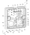
- FIG. 3 is a diagram showing a part of the alarm in Embodiment 1 viewed from the front, with the lid removed.
- FIG. 2 is a perspective view showing a part of the alarm in Embodiment 1, with a lid and a cover member removed.
- FIG. 2 is a diagram showing a part of the alarm in Embodiment 1, viewed from the front side, with a lid and a cover member removed.
- FIG. 3 is an exploded perspective view showing the first substrate unit in the first embodiment.
- FIG. 3 is an exploded perspective view showing the first substrate unit in the first embodiment.
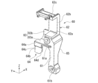
- FIG. 3 is a perspective view showing a cover member in Embodiment 1.
- FIG. 9 is a perspective view showing the cover member in Embodiment 1, and is a view of the cover member viewed from a different angle from that in FIG. 8.
- FIG. FIG. 6 is a diagram illustrating a state in which the sensor board in Embodiment 1 is attached to the housing main body in different postures.
- FIG. 7 is a diagram illustrating a state in which the sensor board in Embodiment 1 is attached to the casing main body in another different orientation.
- FIG. 7 is a diagram illustrating a state in which the sensor board in the first embodiment is attached to the casing main body in yet another different orientation.
- FIG. 7 is a diagram of a part of the notification device in Embodiment 2, seen from the front side.
- FIG. 7 is a diagram illustrating a state in which the sensor board in Embodiment 2 is attached to the housing main body in different postures.
- the drawings appropriately indicate an X axis, a Y axis, and a Z axis.
- the direction along the X-axis will be referred to as the "front-back direction X”
- the direction along the Y-axis will be referred to as the "left-right direction Y”
- the direction along the Z-axis will be referred to as the "up-down direction Z.”
- the front-rear direction X, the left-right direction Y, and the up-down direction Z are directions that are orthogonal to each other.
- the side of the vertical direction Z that the Z-axis arrow points to (+Z side) is referred to as the upper side
- the side of the vertical direction Z that is opposite to the side that the Z-axis arrow points to (-Z side) is referred to as the lower side.
- the front-rear direction X the side toward which the X-axis arrow points (+X side) is the front side
- the front-rear direction X the side opposite to the side toward which the X-axis arrow points (-X side) is the rear side.
- the left-right direction Y is the left-right direction when the notification device of the following embodiment is viewed from the front side (+X side).
- the side of the left-right direction Y that the Y-axis arrow points to (+Y side) is the right side
- the side of the left-right direction Y that is opposite to the side that the Y-axis arrow points to (-Y side) is the left side
- FIG. 1 is a perspective view showing a notification device 100 in the first embodiment.
- FIG. 2 is an exploded perspective view showing the notification device 100 in the first embodiment.
- FIG. 3 is a perspective view showing a part of the alarm 100 according to the first embodiment, with a lid 30 described later removed.
- FIG. 4 is a diagram showing a part of the alarm 100 according to the first embodiment as viewed from the front side, with a lid section 30 described later removed.
- FIG. 5 is a perspective view showing a part of the alarm 100 according to the first embodiment, with the lid 30 and cover member 60, which will be described later, removed.
- FIG. 6 is a diagram showing a part of the alarm 100 according to the first embodiment, viewed from the front side, with a lid 30 and a cover member 60, which will be described later, removed.
- the alarm 100 in the first embodiment shown in FIG. 1 is an alarm that detects a refrigerant and, when the refrigerant is detected, notifies the user that the refrigerant has been detected.
- the refrigerant is, for example, a refrigerant used in a refrigeration cycle device such as an air conditioner.
- the refrigerant include a fluorine-based refrigerant or a hydrocarbon-based refrigerant that has a low global warming potential (GWP).
- the density of the refrigerant in the gaseous case is greater than the density of air.
- the alarm 100 is fixed to, for example, a wall in a room where an indoor unit of an air conditioner is arranged.
- the alarm 100 in the first embodiment has a substantially rectangular parallelepiped shape.
- the alarm 100 has a substantially square shape when viewed in the front-rear direction X and has a pair of sides extending in the left-right direction Y and a pair of sides extending in the up-down direction Z.
- the alarm 100 includes a casing 10 in the shape of a substantially rectangular parallelepiped box.
- the housing 10 is made of resin, for example.
- the housing 10 includes a housing body 20 and a lid 30.
- the housing body 20 and the lid 30 are separate bodies.
- the lid portion 30 is located on the front side (+X side) of the housing main body portion 20.
- the lid part 30 is removably fixed to the housing body part 20.
- the housing main body 20 is box-shaped and opens on the front side (+X side).
- the housing body 20 includes a rear wall 21 , an inner peripheral wall 22 , and a flange 23 .
- the rear wall portion 21 has a substantially square plate shape.
- the plate surface of the rear wall portion 21 faces the front-rear direction X.
- the inner circumferential wall portion 22 projects forward from the outer edge of the rear wall portion 21 .
- the inner circumferential wall portion 22 has a substantially square frame shape when viewed in the front-rear direction X.
- a through hole 22a that penetrates the wall in the vertical direction Z is formed in the center of the upper wall of the inner peripheral wall 22 in the left-right direction Y. .
- the flange portion 23 projects from the outer circumferential surface of the inner circumferential wall portion 22 toward the outside of the inner circumferential wall portion 22 .
- the flange portion 23 has a substantially square frame shape surrounding the inner peripheral wall portion 22 .
- a lid fixing portion 21a is formed at the center of the upper edge of the rear wall portion 21 in the left-right direction Y.
- the lid fixing part 21a projects forward and upward from the front (+X side) surface of the rear wall part 21.
- the lid fixing part 21a is arranged opposite to the lower side of the through hole 22a.
- a bolt for fixing the lid part 30 is tightened into the lid fixing part 21a.
- the housing body 20 and the lid 30 are fixed to each other by the bolts.
- a pair of protruding wall portions 26a and 26b are formed at the center portion in the vertical direction Z at both edges in the left-right direction Y of the front side (+X side) surface of the rear wall portion 21. ing.
- the pair of protruding wall portions 26a and 26b protrude from the rear wall portion 21 to the front side (+X side).
- the pair of protruding walls 26a and 26b are connected to the inner surface of the inner peripheral wall 22.
- the protruding wall portion 26a has a substantially U-shape that opens on the right side when viewed in the front-rear direction X.
- the right end of the protruding wall portion 26a is connected to the wall portion of the inner circumferential wall portion 22 located on the right side.
- the protruding wall portion 26b has a substantially U-shape that opens on the left side when viewed in the front-rear direction X.
- the left end of the protruding wall portion 26b is connected to the wall portion of the inner circumferential wall portion 22 located on the left side.
- a portion of the rear wall portion 21 surrounded by the protruding wall portion 26a when viewed in the front-rear direction A bolt hole is formed through which a bolt for fixing the portion 21 to an indoor wall or the like is passed.
- Board fixing parts 24a and 24b are formed on the front side (+X side) surface of the rear wall part 21.
- the board fixing parts 24a and 24b have a cylindrical shape that protrudes from the rear wall part 21 to the front side.
- the substrate fixing parts 24a and 24b are located below the lid fixing part 21a.
- Female threaded holes into which bolts 70a and 70b for fixing a cover member 60, which will be described later, are tightened are formed at the tips of the board fixing parts 24a and 24b.
- the board fixing part 24a is provided at the center of the front surface of the rear wall part 21 in the left-right direction Y and the up-down direction Z.
- the board fixing part 24b is provided at the lower end of the front surface of the rear wall part 21 at the center in the left-right direction Y.
- the board fixing part 24b is located on the left side and below the board fixing part 24a.
- the housing body 20 is formed with a substrate holding section 29 that holds a sensor substrate 51, which will be described later.
- the substrate holding portion 29 is formed in a lower portion of the right side portion inside the inner circumferential wall portion 22 .
- the substrate holding part 29 has a plurality of ribs 29a.
- the plurality of ribs 29a include a plurality of ribs 29a formed on a wall portion located on the lower side of the inner peripheral wall portion 22, and a plurality of ribs 29a formed on a wall portion located on the right side of the inner peripheral wall portion 22. , and a plurality of ribs 29a formed on the lower wall of the protruding wall 26a.
- the substrate holding part 29 has elastic claw parts 25a, 25b, fixed claw parts 28a, 28b, and support parts 27a, 27b, 27c, 27d.
- the elastic claw portions 25a, 25b, the fixed claw portions 28a, 28b, and the support portions 27a, 27b, 27c, 27d protrude from the rear wall portion 21 to the front side (+X side).
- the elastic claw portions 25a, 25b and the support portions 27a, 27b, 27c, 27d are located on the left side of the substrate holding portion 29.
- the fixing claw parts 28a and 28b are located on the right side of the substrate holding part 29.
- the elastic claw portion 25a and the fixed claw portion 28a are claw portions that removably fix a sensor board 51, which will be described later.
- the elastic claws 25a and 25b are elastically deformable in the left-right direction Y. As shown in FIG. 5, the elastic claw portion 25b is arranged on the left side of the elastic claw portion 25a with a space therebetween. The elastic claw portion 25b projects further forward (+X side) than the elastic claw portion 25a.
- the pair of support parts 27a and 27b are arranged to sandwich the elastic claw part 25a in the vertical direction Z.
- the support portion 27b is located above the support portion 27a.
- the pair of support parts 27c and 27d are arranged to sandwich the elastic claw part 25b in the vertical direction Z.
- the support portion 27d is located above the support portion 27c.
- the support portion 27d is connected to the left side of the support portion 27b.
- the fixed claws 28a and 28b are arranged at positions sandwiching a sensor board 51, which will be described later, in the left-right direction Y between the fixed claws 28a and 28b and the elastic claws 25a and 25b.
- the fixed claw portion 28b is located on the right side of the fixed claw portion 28a.
- the fixed claw portion 28b projects further forward (+X side) than the fixed claw portion 28a.
- the housing main body 20 has an elastic claw part 25c and fixed claw parts 28c and 28d.
- the elastic claw portion 25c and the fixed claw portions 28c and 28d are claw portions that hold a notification element board 41, which will be described later.
- the elastic claw portion 25c and the fixed claw portions 28c and 28d protrude from the rear wall portion 21 to the front side (+X side).
- the elastic claw portion 25c is arranged on the right side of the upper portion of the rear wall portion 21.
- the elastic claw portion 25c is elastically deformable in the left-right direction Y.
- the fixed claw parts 28c and 28d are arranged at the left end of the rear wall part 21.
- the fixed claw portion 28d is located below the fixed claw portion 28c. When viewed in the front-rear direction X, the fixed claw portion 28c and the fixed claw portion 28d are arranged to sandwich the protruding wall portion 26b in the vertical direction Z.
- the lid portion 30 has a substantially rectangular parallelepiped box shape that opens on the rear side (-X side).
- the lid portion 30 covers a first substrate unit 40 and a second substrate unit 50, which will be described later, from the front side (+X side).
- the lid portion 30 has a front wall portion 31 and an outer peripheral wall portion 32.
- the front wall portion 31 has a substantially square plate shape. The plate surface of the front wall portion 31 faces the front-rear direction X.
- the front wall portion 31 is disposed in front of the rear wall portion 21 and facing the rear wall portion 21 with a space therebetween.
- the outer peripheral wall 32 protrudes from the outer edge of the front wall 31 to the rear side (-X side).
- the outer peripheral wall portion 32 has a substantially square frame shape when viewed in the front-rear direction X.
- the inner peripheral wall 22 is fitted inside the outer peripheral wall 32.
- the rear end of the outer peripheral wall 32 is in contact with the front (+X side) surface of the flange 23 .
- a portion 32a is formed.
- the covering portion 32a can be opened and closed. When the covering portion 32a is open, the head of the bolt that fixes the lid portion 30 to the housing main body portion 20 is exposed to the outside of the housing 10.
- An intake hole 33 is formed in the front wall portion 31 of the lid portion 30.
- the intake hole 33 is formed at the lower end of the left side portion of the front wall portion 31 .
- the intake hole 33 extends in the vertical direction Z.
- a plurality of intake holes 33 are provided at intervals in the left-right direction Y. In the first embodiment, three intake holes 33 are provided.
- a stop switch 34 is provided in a portion of the front wall portion 31 located above the intake hole 33. The user can stop the notification by the notification device 100 by pressing the stop switch 34.
- a plurality of windows 35 are formed in a portion of the front wall 31 located above the stop switch 34 and arranged at intervals in the vertical direction Z.
- the lid portion 30 is removably fixed to the housing body portion 20.
- An operator who removes the lid part 30 from the housing body part 20 opens the cover part 32a of the lid part 30 to expose the head of the bolt that fixes the lid part 30 to the housing body part 20, and removes the bolt. Thereby, the operator can remove the lid section 30 from the housing main body section 20.
- the alarm 100 includes a first board unit 40 and a second board unit 50.
- the first board unit 40 and the second board unit 50 are housed inside the housing 10.
- the first board unit 40 is held across the left side portion and the upper portion of the housing body 20.
- the second board unit 50 is held by the board holding section 29.
- FIG. 7 is an exploded perspective view showing the first board unit 40.
- the first board unit 40 includes a notification element board 41, a speaker 42, a terminal block 43, a switch element 44, a light emitter 45, a first connector 46, and electrical components 47a, 47b. , 47c.
- the notification element substrate 41 has a plate shape with a plate surface facing in the front-rear direction X.
- the plate surface of the notification element board 41 is perpendicular to the front-rear direction X.
- a speaker 42, a terminal block 43, a switch element 44, a light emitter 45, a first connector 46, and electrical components 47a, 47b, and 47c are attached to the front side (+X side) surface of the notification element board 41.
- the speaker 42, the terminal block 43, the switch element 44, the light emitter 45, the first connector 46, and the electrical components 47a, 47b, and 47c are electrically connected to the notification element board 41.
- the speaker 42, the terminal block 43, the switch element 44, the light emitter 45, the first connector 46, and the electrical components 47a, 47b, and 47c are electrically connected to the notification element board 41 by, for example, soldering.
- the notification element board 41 is a printed circuit board having a conductor wiring pattern.
- the notification element substrate 41 has a first portion 41a, a second portion 41b, a third portion 41c, a fourth portion 41d, and a fifth portion 41e.
- the first portion 41a extends in the vertical direction Z.
- the second portion 41b projects to the left from the upper end of the first portion 41a.
- the third portion 41c projects to the right from the first portion 41a.
- the upper end of the third portion 41c is located below the upper end of the first portion 41a.
- the fourth portion 41d projects to the left from the lower portion of the first portion 41a.
- the fourth portion 41d is arranged below the second portion 41b with a space therebetween.
- the fifth portion 41e protrudes to the right from the lower end of the first portion 41a.
- the right end of the fifth portion 41e is located to the left of the right end of the third portion 41c.
- the fifth portion 41e is arranged below the left end portion of the third portion 41c with a space therebetween.
- Bolt holes 48a and 48b passing through the notification element board 41 in the front-rear direction X are formed in the notification element board 41.
- the bolt hole 48a is formed at the left end of the lower end of the third portion 41c.
- a bolt 70a that is tightened into a female screw hole of the board fixing portion 24a is passed through the bolt hole 48a.
- the bolt hole 48b is formed at a connecting portion between the first portion 41a and the fifth portion 41e.
- a bolt 70b that is tightened into a female screw hole of the board fixing portion 24b is passed through the bolt hole 48b.
- the notification element board 41 is held in the housing body 20.
- the notification element board 41 has a structure in which the elastic claw part 25c and the fixed claw parts 28c, 28d are hooked on the edge of the notification element board 41 from the front side (+X side), and are inserted through the bolt holes 48a, 48b.
- the board fixing parts 24a and 24b are fixed to the main body part 20 by tightening the bolts 70a and 70b into the female screw holes of the board fixing parts 24a and 24b.
- the elastic claw portion 25c is hooked onto the right edge of the third portion 41c from the front side.
- the fixed claw portion 28c is hooked onto the left edge of the second portion 41b from the front side.
- the fixed claw portion 28d is hooked onto the left edge of the fourth portion 41d from the front side.
- the speaker 42 has a cylindrical shape centered on an axis extending in the front-rear direction X.
- the speaker 42 is arranged across the first portion 41a and the fourth portion 41d.
- the speaker 42 is a notification element that can notify that a refrigerant sensor 52, which will be described later, has detected a refrigerant.
- the speaker 42 notifies the user etc. that the refrigerant sensor 52 has detected the refrigerant through sound.
- the speaker 42 is, for example, a buzzer that generates a simple continuous sound.
- the speaker 42 When the refrigerant sensor 52 detects refrigerant, for example, the speaker 42 outputs a simple continuous sound as a warning sound to notify that refrigerant is leaking from the indoor unit of the air conditioner.
- the speaker 42 may be a speaker that, when the refrigerant sensor 52 detects refrigerant, plays a sound to notify the user that refrigerant is leaking from the indoor unit of the air conditioner.
- the terminal block 43 is arranged in the third portion 41c. As shown in FIG. 4, the terminal block 43 has a plurality of connection parts 43a, 43b, 43c, and 43d. In the first embodiment, the plurality of connecting portions 43a, 43b, 43c, and 43d are holes that open on the right side. The connecting portions 43a, 43b, and 43b are arranged in this order from the top to the bottom.
- a wiring 81a is connected to the connection portion 43a.
- a wiring 81b is connected to the connection portion 43b.
- a wiring 81c is connected to the connection portion 43c.
- a wiring 81d is connected to the connection portion 43d.
- Each wiring 81a, 81b, 81c, 81d is electrically connected to the notification element board 41 via the terminal block 43.
- the wiring 81a is a power supply line.
- the wiring 81b and the wiring 81d are signal lines.
- the wiring 81c is a ground wire.
- Each of the wirings 81a, 81b, 81c, and 81d is led out of the housing 10 through, for example, a through hole 22a formed in the inner peripheral wall portion 22.
- the wiring 81a and the wiring 81c are connected to an external power source provided outside the alarm 100.
- the wiring 81b and the wiring 81d are connected to an electronic device provided outside the alarm 100. Power is supplied to the alarm 100 from an external power source via a wiring 81a that is a power line.
- the wiring connected to the terminal block 43 may include wiring electrically connected to other components within the casing 10.
- the wiring connected to the terminal block 43 may include wiring electrically connected to the sensor board 51 described below.
- the wiring 81b or the wiring 81d described above may be electrically connected to the sensor board 51.
- the switch element 44 is arranged at the center of the first portion 41a in the vertical direction Z.
- the switch element 44 is located on the rear side ( ⁇ X side) of the stop switch 34 of the lid portion 30.
- the light emitter 45 is arranged in the upper part of the first part 41a.
- the light emitter 45 is, for example, a light emitting diode (LED).
- a plurality of light emitters 45 are arranged in a row at intervals in the vertical direction Z.
- three light emitters 45 are provided: a light emitter 45a, a light emitter 45b, and a light emitter 45c.
- the light emitter 45a, the light emitter 45b, and the light emitter 45c are arranged side by side in this order from the top to the bottom at intervals.
- the light emitter 45a is a light emitter 45 that indicates the power input state of the alarm 100.
- the light emitter 45a emits light when power is supplied to the alarm 100.
- the light emitter 45b is a notification element that can notify that a refrigerant sensor 52, which will be described later, has detected a refrigerant.
- the light emitter 45b emits light when the refrigerant sensor 52 detects refrigerant.
- the light emitter 45c is a light emitter 45 that indicates that some kind of malfunction has occurred in the notification device 100.
- the light emitter 45c emits light when some kind of malfunction occurs in the alarm 100.
- each of the light emitters 45a, 45b, and 45c is emitted to the outside of the housing 10 through each window 35 formed in the lid 30. Thereby, the user and the like can visually recognize the light emitted from each of the light emitters 45a, 45b, and 45c from outside the alarm 100.
- the first connector 46 is arranged at the right end of the lower end of the third portion 41c.
- the first connector 46 is located below the terminal block 43.
- a cable 80 connecting the notification element board 41 and a sensor board 51, which will be described later, is connected to the first connector 46.
- the cable 80 includes a plurality of wires 80a extending from the first connector 46 and a cable connector 80b to which the tips of the plurality of wires 80a are connected.
- the notification element board 41 and the sensor board 51 are electrically connected via the cable 80 by connecting the cable connector 80b to a second connector 53, which will be described later.
- the electrical components 47a, 47b, and 47c have a cylindrical shape extending in the front-rear direction X.
- the electrical components 47a, 47b, 47c are, for example, capacitors.
- the electrical component 47a is arranged at the left end of the upper portion of the second portion 41b.
- the electrical component 47c is arranged at the left end of the upper end of the third portion 41c.
- the electrical component 47c is arranged at the center in the left-right direction Y at the lower end of the third portion 41c.
- the electrical component 47c is located between the bolt hole 48a and the first connector 46 in the left-right direction Y.
- the second board unit 50 is held by the board holding section 29.
- the second board unit 50 is located below the third portion 41c of the notification element board 41 and to the right of the lower portion of the first portion 41a and the fifth portion 41e.
- the second board unit 50 includes a sensor board 51, a refrigerant sensor 52, a second connector 53, and an IC chip 54.
- the sensor board 51 is separate from the notification element board 41.
- the sensor board 51 is placed apart from the notification element board 41.
- the sensor substrate 51 is located below the third portion 41c of the notification element substrate 41 and on the right side of the lower portion of the first portion 41a and the fifth portion 41e.
- the sensor substrate 51 has a square plate shape with a plate surface facing in the front-rear direction X.
- the plate surface of the sensor board 51 is perpendicular to the front-rear direction X.
- the sensor substrate 51 has a square plate shape having a pair of sides extending in the left-right direction Y and a pair of sides extending in the up-down direction Z.
- the front side (+X side) surface of the sensor board 51 is the mounting surface 51a.
- a refrigerant sensor 52, a second connector 53, and an IC chip 54 are attached to the attachment surface 51a.
- Refrigerant sensor 52, second connector 53, and IC chip 54 are electrically connected to sensor board 51.
- Refrigerant sensor 52, second connector 53, and IC chip 54 are electrically connected to sensor board 51 by, for example, soldering.
- the sensor board 51 is a printed circuit board having a conductor wiring pattern.
- the sensor board 51 is held in the housing main body part 20.
- the sensor substrate 51 is held by the substrate holding section 29.
- the sensor board 51 is surrounded by the supporting parts 27a, 27b and a plurality of ribs 29a, and the outer peripheral edge part is supported, and the elastic claw part 25a and the fixed claw part 28a are connected to the outside of the sensor board 51. It is held by the substrate holding part 29 by being caught on the peripheral edge from the front side (+X side).
- the elastic claw portion 25a is hooked onto the left edge of the sensor board 51 from the front side.
- the fixed claw portion 28a is hooked onto the right edge of the sensor board 51 from the front side.
- the support portion 27a supports the corner portion of the sensor substrate 51 located on the left side and lower side from the left side.
- the support portion 27b supports the corner portion located on the left side and the upper side of the sensor substrate 51 from the left side and the upper side.
- a plurality of ribs 29a formed on the lower wall of the inner circumferential wall 22 support the lower edge of the sensor substrate 51 from below.
- a plurality of ribs 29a formed on the right side of the inner circumferential wall 22 support the right edge of the sensor substrate 51 from the right side.
- a plurality of ribs 29a formed on the lower wall of the protruding wall 26a support the upper edge of the sensor substrate 51 from above.
- the refrigerant sensor 52 is a sensor that can detect refrigerant.
- the refrigerant sensor 52 is a semiconductor refrigerant sensor.
- the refrigerant sensor 52 is capable of detecting a gaseous refrigerant sensor 52 .
- the refrigerant sensor 52 has a cylindrical shape extending from the sensor board 51 to the front side (+X side).
- the refrigerant sensor 52 is attached to the lower portion of the left side portion of the sensor board 51.
- the refrigerant sensor 52 detects the refrigerant. Therefore, for example, by placing the alarm 100 vertically below the indoor unit in an air conditioner, the refrigerant sensor 52 can detect the refrigerant that has leaked from the indoor unit and flowed vertically downward.
- the second connector 53 is attached to the right side portion of the sensor board 51.
- a cable connector 80b of a cable 80 extending from the first connector 46 is detachably connected to the second connector 53.
- the sensor board 51 is electrically connected to the notification element board 41 by electrically connecting the first connector 46 and the second connector 53 with the cable 80 .
- the second connector 53 corresponds to a "first electrical component" attached to the sensor board 51.
- the IC chip 54 is attached to the upper portion of the left side portion of the sensor board 51.
- the IC chip 54 has a square plate shape with a plate surface facing in the front-rear direction X.
- the IC chip 54 is located above the refrigerant sensor 52 and to the left of the second connector 53.
- the front side (+X side) surface of the IC chip 54 is located on the rear side ( ⁇ X side) of the front end of the refrigerant sensor 52 and the front end of the second connector 53.
- the protrusion height of the IC chip 54 from the mounting surface 51a is smaller than the protrusion height of the refrigerant sensor 52 from the mounting surface 51a and the protrusion height of the second connector 53 from the mounting surface 51a.
- the protruding height of the IC chip 54 from the mounting surface 51a, the protruding height of the refrigerant sensor 52 from the mounting surface 51a, and the protruding height of the second connector 53 from the mounting surface 51a are as follows. It is the same as the dimension in the front-rear direction X of each component.
- the IC chip 54 When the refrigerant sensor 52 detects refrigerant, the IC chip 54 sends a signal indicating that the refrigerant sensor 52 has detected the refrigerant to the notification element board 41 via the cable 80. When the signal is sent from the IC chip 54 to the notification element board 41, the light emitter 45b lights up and the speaker 42 makes a sound to notify that the refrigerant has leaked.
- the IC chip 54 corresponds to a "second electrical component" attached to the mounting surface 51a.
- the alarm 100 includes a cover member 60 disposed inside the housing 10.
- the cover member 60 extends in the vertical direction Z.
- the cover member 60 is made of resin, for example.
- the cover member 60 is fixed to the housing body 20 while covering a part of the notification element board 41.
- the cover member 60 covers a part of the notification element board 41 from the front side (+X side). More specifically, the cover member 60 covers the right end of the lower portion of the first portion 41a, the left end of the third portion 41c, and the fifth portion 41e of the notification element substrate 41 from the front side.
- the cover member 60 sandwiches a part of the notification element board 41 in the front-rear direction X between the cover member 60 and the housing main body part 20.
- FIG. 8 is a perspective view showing the cover member 60.
- FIG. 9 is a perspective view showing the cover member 60, and is a view of the cover member 60 seen from a different angle from that in FIG.
- the cover member 60 includes an extending portion 61, a first protruding portion 62, a second protruding portion 63, a facing portion 64, and a side wall portion 65.
- the extending portion 61 extends in the vertical direction Z.
- the extending portion 61 has a plate shape with a plate surface facing in the front-rear direction X.
- Bolt holes 61a and 61b are formed in the extending portion 61, passing through the extending portion 61 in the front-rear direction X.
- the bolt hole 61a is formed at the upper end of the extending portion 61.
- the bolt hole 61b is formed at the lower end of the extending portion 61.
- a bolt 70a for fixing the notification element board 41 is passed through the bolt hole 61a from the front side (+X side).
- a bolt 70b for fixing the notification element board 41 is passed through the bolt hole 61b from the front side.
- the bolts 70a and 70b are passed through the bolt holes 61a and 61b and the bolt holes 48a and 48b formed in the notification element board 41, respectively, and tightened into the female screw holes of the board fixing parts 24a and 24b, respectively.
- the cover member 60 is fixed to the housing main body 20 together with the notification element board 41. That is, in the first embodiment, the cover member 60 and the notification element board 41 are fastened together to the housing main body part 20 with bolts 70a and 70b.
- the peripheral edge of the bolt hole 61a and the peripheral edge of the bolt hole 61b of the rear side ( ⁇ X side) surface of the extending portion 61 protrude rearward.
- the protruding portion is in contact with the front side (+X side) surface of the notification element board 41.
- the cover member 60 is in contact with the notification element substrate 41.
- the first protruding portion 62 is connected to the upper side of the extending portion 61.
- the first protruding portion 62 protrudes from the upper end of the extending portion 61 toward the front side (+X side).
- the first protruding portion 62 includes a first wall portion 62a that protrudes forward from the upper end of the extending portion 61, a second wall portion 62b extending upward from the front end of the first wall portion 62a, and a second wall portion 62b that extends upward from the front end of the first wall portion 62a. It has a third wall portion 62c extending from the upper end toward the rear side (-X side).
- the first protrusion 62 covers the electrical component 47b from the front side (+X side). More specifically, the second wall portion 62b of the first protrusion 62 covers the electrical component 47b from the front side.
- the first wall portion 62a and the third wall portion 62c of the first protruding portion 62 are arranged to sandwich the electrical component 47b in the vertical direction Z.
- the second wall portion 62b covers the third portion 41c of the notification element substrate 41 from the front side.
- the second wall portion 62b is arranged adjacent to the left side of the terminal block 43 when viewed from the front side.
- each display section 66a, 66b, 66c, 66d is a character formed on the front surface of the second wall section 62b.
- the display section 66a includes the characters "VDD”.
- the display section 66b includes the characters "SIG1”.
- the display section 66c includes the characters "GND”.
- the display section 66d includes the characters "SIG2".
- each of the plurality of display parts 66a, 66b, 66c, and 66d formed on the second wall part 62b has a plurality of connection parts. It is arranged adjacent to each of 43a, 43b, 43c, and 43d in the left-right direction Y.
- the display section 66a is arranged on the left side of the connection section 43a.
- the display section 66b is arranged on the left side of the connection section 43b.
- the display section 66c is arranged on the left side of the connection section 43c.
- the display section 66d is arranged on the left side of the connection section 43d.
- the plurality of display parts 66a, 66b, 66c, and 66d each show information regarding the wirings 81a, 81b, 81c, and 81d connected to the plurality of connection parts 43a, 43b, 43c, and 43d.
- the plurality of display sections 66a, 66b, 66c, and 66d indicate the type of each wiring 81a, 81b, 81c, and 81d as information regarding the wiring 81a, 81b, 81c, and 81d.
- the display section 66a indicates that the wiring 81a connected to the connection section 43a is a power supply line.
- the display section 66b indicates that the wiring 81b connected to the connection section 43b is a signal line.
- the display section 66c indicates that the wiring 81c connected to the connection section 43c is a ground wire.
- the display section 66d indicates that the wiring 81d connected to the connection part 43d is a different signal line from the wiring 81b connected to the connection part 43b.
- the second protruding portion 63 is connected to the right side of the upper end portion of the extending portion 61.
- the second protruding portion 63 protrudes from the extending portion 61 toward the front side (+X side).
- the second protrusion 63 has a first wall 63a that protrudes forward from the extension 61, and a second wall 63b that extends upward from the front end of the first wall 63a.
- the connecting portion between the first wall portion 63a and the second wall portion 63b is rounded.
- the second protrusion 63 has a substantially arc shape when viewed in the left-right direction Y.
- the left end of the upper end of the second wall 63b is connected to the second wall 62b of the first protrusion 62.
- the second protrusion 63 covers the electrical component 47c from the front side.
- the side wall portion 65 protrudes from the left end portion of the extending portion 61 and the left end portion of the first protrusion portion 62 to the front side (+X side).
- the side wall portion 65 extends in the vertical direction Z.
- the side wall portion 65 is arranged to face the right side of the speaker 42.
- the opposing portion 64 is connected to the lower end of the second protrusion 63.
- the opposing portion 64 protrudes downward from the rear ( ⁇ X side) end of the first wall portion 63a.
- the opposing portion 64 has a plate shape with a plate surface facing in the front-rear direction X.
- the opposing portion 64 has a substantially rectangular plate shape.
- the opposing portion 64 is formed at a center portion in the left-right direction Y on the front side (+X side) surface of the base portion 64a. It has a rib 64e.
- a step portion 64c is provided between the base portion 64a and the opposing main body portion 64b, which projects toward the front side (+X side) when the opposing portion 64 is traced from the base portion 64a toward the opposing main body portion 64b.
- the opposing main body portion 64b is located on the front side of the base portion 64a.
- the rib 64e extends in the vertical direction Z and connects the opposing main body portion 64b and the first wall portion 63a.
- a notch 64d is formed at the lower and left end of the opposing main body 64b.
- the cutout portion 64d extends toward the upper side toward the left side when viewed in the front-rear direction X. As shown in FIG. 4, the formation of the notch portion 64d prevents the facing portion 64 from interfering with the elastic claw portion 25a.
- the opposing portion 64 is arranged to face the sensor substrate 51.
- the opposing portion 64 is disposed facing the front side (+X side) of the sensor board 51 with an interval therebetween. That is, the opposing portion 64 is disposed facing the mounting surface 51a with a space therebetween.
- the opposing portion 64 covers the upper end of the left end of the sensor substrate 51 from the front side.
- the distance between the facing portion 64 and the mounting surface 51a is smaller than the dimension of the refrigerant sensor 52 in the front-rear direction X and the dimension of the second connector 53 in the front-rear direction X. That is, the protrusion height of the refrigerant sensor 52 from the mounting surface 51a and the protrusion height of the second connector 53 from the mounting surface 51a are larger than the distance between the facing portion 64 and the mounting surface 51a.
- the distance between the opposing main body portion 64b and the mounting surface 51a is larger than the dimension of the IC chip 54 in the front-rear direction X.
- the opposing portion 64 covers at least a portion of the IC chip 54 from the front side (+X side). As a result, at least a portion of the IC chip 54 is disposed between the facing portion 64 and the sensor substrate 51 in the front-rear direction X.
- the opposing main body portion 64b of the opposing portion 64 covers the left side portion of the IC chip 54 from the front side. That is, in the first embodiment, the left side portion of the IC chip 54 is located between the facing portion 64 and the sensor substrate 51 in the front-rear direction X.
- the opposing portion 64 interferes with at least one of the refrigerant sensor 52 and the second connector 53 when the sensor board 51 is attached to the housing body 20 in a different orientation. This will be explained in detail below.
- the sensor substrate 51 is attached to the substrate holder 29 in three postures, that is, the posture shown in FIG. 10A, the posture shown in FIG. 10B, and the posture shown in FIG. 10C, in addition to the postures shown in FIGS. 3 to 6. It can be attached to.
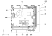
- FIG. 10A is a diagram showing a state in which the sensor board 51 is attached to the housing main body 20 in different postures.
- FIG. 10B is a diagram showing a state in which the sensor board 51 is attached to the housing main body 20 in another different orientation.
- FIG. 10C is a diagram showing a state in which the sensor board 51 is attached to the housing body 20 in yet another different posture.
- the posture of the sensor board 51 shown in FIG. 10A is obtained by rotating the sensor board 51 in the postures shown in FIGS. 3 to 6 by 90 degrees clockwise when viewed from the front side (+X side).
- the attitude of the sensor board 51 shown in FIG. 10B is obtained by rotating the sensor board 51 in the attitude shown in FIGS. 3 to 6 clockwise by 180 degrees when viewed from the front side.
- the posture of the sensor board 51 shown in FIG. 10C is a posture obtained by rotating the sensor board 51 in the postures shown in FIGS. 3 to 6 clockwise by 270 degrees when viewed from the front side.
- the postures of the sensor substrate 51 shown in FIGS. 3 to 6 are correct postures
- the postures of the sensor substrate 51 shown in FIGS. 10A to 10C are incorrect postures.
- a part of the refrigerant sensor 52 is arranged at a position overlapping with the facing portion 64 when viewed in the front-rear direction X. Since the refrigerant sensor 52 protrudes further forward (+X side) than the facing part 64, if the refrigerant sensor 52 is placed in a position overlapping the facing part 64 in the front-rear direction X, the facing part 64 will interfere with the refrigerant sensor 52. Therefore, the facing portion 64 cannot be arranged. Therefore, if the sensor board 51 is attached to the housing body 20 in the attitude shown in FIG. 10A, the cover member 60 cannot be attached to the housing body 20.
- the opposing part 64 will interfere with at least one of the refrigerant sensor 52 and the second connector 53. Therefore, it is no longer possible to attach the cover member 60 to the housing main body part 20.
- the sensor board 51 is attached to the housing main body part 20 in the correct posture as shown in FIGS. can be attached to the housing main body part 20.
- the operator who replaces the refrigerant sensor 52 first removes the lid portion 30 from the housing body portion 20, and then removes the bolts 70a and 70b to remove the cover member 60.
- the operator removes the cable connector 80b of the cable 80 from the second connector 53, elastically deforms the elastic claw portion 25a to the left, removes it from the sensor board 51, and moves the second board unit 50 to the board holder. Remove from 29.
- the operator attaches a new second board unit 50 having a new refrigerant sensor 52 to the board holding part 29, and then fixes the cover member 60 to the housing body part 20 again with bolts 70a and 70b.
- the operator fixes the lid section 30 to the housing body section 20 again. With the above steps, the operator can replace the refrigerant sensor 52.
- the alarm 100 includes a refrigerant sensor 52 capable of detecting a refrigerant, a speaker 42 and a light emitting body 45b as a notification element capable of informing that the refrigerant sensor 52 has detected a refrigerant, and a speaker 42. and a notification element board 41 to which a light emitting body 45b is attached, a sensor board 51 to which a refrigerant sensor 52 is attached, and a casing 10 that accommodates the notification element board 41 and the sensor board 51 inside.
- the sensor board 51 is separate from the notification element board 41 and is electrically connected to the notification element board 41.
- the casing 10 includes a casing main body part 20 holding a notification element board 41 and a sensor board 51, a lid part 30 that is removably fixed to the casing main body part 20 and covers the notification element board 41 and the sensor board 51. , has.
- the housing body section 20 has an elastic claw section 25a and a fixing claw section 28a as claw sections for removably fixing the sensor board 51.
- the sensor board 51 to which the refrigerant sensor 52 is attached can be removed from the casing main body 20 without removing the notification element board 41 from the casing main body 20.
- This makes it possible to replace the speaker 42 and the light emitter 45b as notification elements when the semiconductor type refrigerant sensor 52 detects the refrigerant and the refrigerant is used, or when a malfunction occurs in the refrigerant sensor 52 or the like. Therefore, the refrigerant sensor 52 can be replaced. Therefore, the effort and cost required for replacing the refrigerant sensor 52 can be reduced.
- the refrigerant sensor 52 in the alarm 100 can be easily replaced.
- the first substrate unit 40 can also be removed by removing the lid portion 30 and the cover member 60. Thereby, the operator can also easily replace the speaker 42 and the light emitting body 45b as the notification elements attached to the notification element board 41.
- the alarm 100 includes the cover member 60 disposed inside the housing 10.
- the cover member 60 is fixed to the housing body 20 while covering a part of the notification element board 41. Therefore, a part of the notification element board 41 can be protected by the cover member 60. Thereby, damage to the notification element board 41 and the components attached to the notification element board 41 can be suppressed. Further, it is possible to prevent the user from unintentionally touching the notification element board 41 and the parts attached to the notification element board 41. Further, since the notification element board 41 can be held down by the cover member 60, it is easy to stably hold the notification element board 41 within the housing 10.
- the cover member 60 sandwiches a part of the notification element board 41 with the housing main body part 20 and is in contact with the notification element board 41. Therefore, the cover member 60 can more stably fix the notification element board 41 to the casing main body part 20.
- the cover member 60 and the notification element board 41 are fastened together to the housing main body part 20 with bolts 70a and 70b. Therefore, the cover member 60 and the notification element board 41 can be easily and firmly fixed to the housing body 20. By being able to firmly fix the notification element substrate 41, it is possible to suppress the notification element substrate 41 from vibrating due to the vibration of the speaker 42 when sound is transmitted from the speaker 42. Thereby, it is possible to suppress the generation of noise other than the notification sound played from the speaker 42.
- the alarm 100 includes the second connector 53 as the first electrical component attached to the sensor board 51.
- the cover member 60 has a facing portion 64 arranged to face the sensor substrate 51 .
- the opposing portion 64 interferes with at least one of the refrigerant sensor 52 and the second connector 53 when the sensor board 51 is attached to the housing body 20 in a different orientation. Therefore, as described above, when the sensor board 51 is attached to the housing main body part 20 in an incorrect orientation, the opposing part 64 interferes with at least one of the refrigerant sensor 52 and the second connector 53, and the cover member 60 cannot be attached.
- the operator can be made aware that the sensor board 51 is attached in an incorrect orientation, and it is possible to prevent the sensor board 51 from being attached to the housing main body part 20 in an incorrect orientation. Therefore, for example, it is possible to prevent the position of the refrigerant sensor 52 attached to the sensor board 51 from becoming far from the intake hole 33, and it is possible to prevent the refrigerant sensor 52 from becoming difficult to detect the refrigerant. Furthermore, for example, the position of the second connector 53 can be prevented from being far away from the first connector 46 attached to the notification element board 41, and the notification element board 41 and the sensor board 51 can be connected by the cable 80. This can prevent it from becoming difficult.
- the sensor board 51 has the mounting surface 51a to which the refrigerant sensor 52 and the second connector 53 as the first electric component are attached.
- the opposing portion 64 is disposed facing the mounting surface 51a with a space therebetween.
- the protruding height of the refrigerant sensor 52 from the mounting surface 51a and the protruding height of the second connector 53 from the mounting surface 51a are larger than the distance between the opposing portion 64 and the mounting surface 51a. Therefore, when viewed in the front-rear direction X perpendicular to the mounting surface 51a, the opposing portion 64 cannot be placed overlapping the refrigerant sensor 52 and the second connector 53.
- the facing portion 64 can suitably interfere with at least one of the refrigerant sensor 52 and the second connector 53. Therefore, it is possible to more preferably prevent the sensor board 51 from being attached to the housing main body part 20 in an incorrect orientation.
- the alarm 100 includes the IC chip 54 as the second electrical component attached to the mounting surface 51a. At least a portion of the IC chip 54 is disposed between the facing portion 64 and the sensor substrate 51. Therefore, when the sensor board 51 is attached in the correct posture, at least a part of the part of the sensor board 51 that faces the facing part 64 is used as an arrangement area for the IC chip 54, which is a component that does not interfere with the facing part 64. can. Thereby, even if the facing portion 64 is made to face the mounting surface 51a, it is possible to suppress the mounting area of the mounting surface 51a from decreasing.
- the opposing main body part 64b is prevented from interfering with the IC chip 54 by providing the step part 64c in the opposing part 64 and separating the opposing main body part 64b further to the front (+X side) from the mounting surface 51a. are doing.
- the notification device 100 includes a terminal block 43 that has a plurality of connection parts 43a, 43b, 43c, and 43d and is attached to the notification element board 41.
- the cover member 60 has a plurality of display parts 66a, 66b, 66c, and 66d that respectively show information regarding the wirings 81a, 81b, 81c, and 81d connected to the plurality of connection parts 43a, 43b, 43c, and 43d. Therefore, when connecting the plurality of wirings 81a, 81b, 81c, 81d to the plurality of connection parts 43a, 43b, 43c, 43d, respectively, the operator should refer to each display part 66a, 66b, 66c, 66d.
- each of the plurality of display parts 66a, 66b, 66c, and 66d has a plurality of connection parts 43a, It is arranged adjacent to each of 43b, 43c, and 43d. Therefore, the operator can appropriately grasp the wirings 81a, 81b, 81c, 81d to be connected to the respective connection parts 43a, 43b, 43c, 43d by referring to each display part 66a, 66b, 66c, 66d. I can do it. Thereby, it is possible to more preferably suppress the connection of incorrect wirings 81a, 81b, 81c, and 81d to each of the connection portions 43a, 43b, 43c, and 43d.
- the notification element attached to the notification element substrate 41 includes at least one of the speaker 42 and the light emitter 45b. Therefore, the alarm 100 can notify the user and the like that the refrigerant has leaked using at least one of sound and light. Thereby, it is possible to suitably notify the user or the like that the refrigerant has leaked.
- the speaker 42 and the light emitter 45b are provided as notification elements, it is possible to more appropriately notify the user and the like that the refrigerant has leaked.
- FIG. 11 is a diagram of a part of the notification device 200 according to the second embodiment, viewed from the front side (+X side).
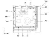
- FIG. 12 is a diagram showing a state in which the sensor board 251 according to the second embodiment is attached to the housing main body 20 in a different orientation.
- the attitude of the sensor board 251 shown in FIG. 12 is obtained by rotating the sensor board 251 in the attitude shown in FIG. 11 by 180 degrees clockwise when viewed from the front side (+X side).
- the attitude of the sensor board 251 shown in FIG. 11 is the correct attitude
- each attitude of the sensor board 251 shown in FIG. 12 is an incorrect attitude. Note that, in the following description, the same components as those in the embodiment described above may be given the same reference numerals as appropriate, and the description thereof may be omitted.
- the second board unit 250 includes a sensor board 251, a refrigerant sensor 52, a second connector 53, and an IC chip 254.
- the refrigerant sensor 52, the second connector 53, and the IC chip 254 are attached to the mounting surface 251a, which is the front (+X side) surface of the sensor board 251.
- the sensor board 251 has a substantially rectangular plate shape that is long in the left-right direction Y.
- a chamfered portion 251c is formed at the left and lower corner of the square of the sensor substrate 251 by chamfering the corner.
- a chamfered portion 251d is formed at the left and upper corner of the square of the sensor substrate 251 by chamfering the corner.
- the sensor board 251 is held by the same board holding part 29 as in the first embodiment.
- the sensor board 251 is surrounded by supporting parts 27c and 27d and a plurality of ribs 29a and supported at its outer peripheral edge, and the elastic claw part 25b and the fixed claw part 28b are connected to the outside of the sensor board 251. It is held by the substrate holding part 29 by being caught on the peripheral edge from the front side (+X side).
- the elastic claw portion 25b is hooked onto the left edge of the sensor board 251 from the front side.
- the fixed claw portion 28b is hooked onto the right edge of the sensor board 251 from the front side.
- the board holding part 29 in the housing main body 20 described in the first embodiment has a substantially square plate-like sensor board 51 as in the first embodiment, and a substantially rectangular plate as in the second embodiment.
- a shaped sensor board 251 can also be attached.
- the elastic claw portion 25b and the fixed claw portion 28b are claw portions that removably fix the sensor board 251.
- the chamfered portion 251c is arranged to face the support portion 27c.
- the surface of the support portion 27c that faces the chamfered portion 251c extends along the chamfered portion 251c when viewed in the front-rear direction X.
- the chamfered portion 251d is arranged to face the support portion 27d.
- the surface of the support portion 27d that faces the chamfered portion 251d extends along the chamfered portion 251d when viewed in the front-rear direction X.
- the other configurations of the sensor board 251 are the same as the other configurations of the sensor board 51 in the first embodiment.
- the IC chip 254 is attached to the center of the lower portion of the sensor board 251 in the left-right direction Y.
- the IC chip 254 is located on the right side of the refrigerant sensor 52 and on the left side of the second connector 53.
- the IC chip 254 is not disposed between the facing portion 64 and the sensor substrate 251.
- the other configurations of IC chip 254 are similar to the other configurations of IC chip 54 in the first embodiment.
- the other configurations of the notification device 200 are the same as the other configurations of the notification device 100 in the first embodiment.
- the second connector 53 interferes with the opposing part 64 as in the first embodiment. . Therefore, in the second embodiment as well, it is possible to prevent the sensor board 251 from being attached to the housing main body 20 in an incorrect orientation.
- chamfered portions 251c and 251d are provided at only two corners of the squares of the sensor substrate 251 having a substantially rectangular plate shape, and chamfered portions 251c and 251d are provided on the substrate holding portion 29, respectively.
- the supporting parts 27c and 27d that are arranged opposite to each other, it is also possible to prevent the sensor board 251 from being attached to the housing main body part 20 in an incorrect orientation.
- the non-chamfered corner portions can be made to interfere with the support portions 27c and 27d. Thereby, it is possible to prevent the sensor board 251 from being attached to the board holding section 29 in an incorrect orientation.
- the sensor board 251 shown in FIG. 12 has all of its squares chamfered, so even if the sensor board 251 shown in FIG. It can be held in the section 29. However, as described above, when the sensor board 251 is arranged in this position, the facing portion 64 interferes with the second connector 53, so the cover member 60 cannot be attached. Therefore, even if all the squares of the sensor board 251 are chamfered as shown in FIG. 12, it is possible to prevent the sensor board 251 from being attached to the housing body 20 in an incorrect orientation.
- the refrigerant sensor may be any element as long as it can detect the refrigerant.
- the refrigerant sensor may be a refrigerant sensor other than a semiconductor type.
- the notification element may be any element as long as it can notify that the refrigerant sensor has detected the refrigerant.
- the notification element may be, for example, a display device such as a display capable of displaying characters indicating that refrigerant has been detected.
- the number of notification elements is not particularly limited as long as it is one or more.
- the first electric component and the second electric component attached to the sensor board may be any type of component.
- the first electrical component may be, for example, a capacitor.
- the second electrical component may be, for example, a transistor.
- the cover member may have any configuration as long as it is fixed to the housing body while covering a part of the notification element board.
- the cover member does not need to come into contact with the notification element substrate.
- the cover member may be fixed to the housing body separately from the notification element board.
- the opposing portion disposed to face the sensor board may interfere with both the refrigerant sensor and the first electrical component when the sensor board is attached in different postures with respect to the housing main body.
- the shape of the opposing portion is not particularly limited.
- the cover member does not need to have a facing portion.
- the plurality of display sections formed on the cover member may have any configuration as long as they each indicate information regarding the wiring connected to the plurality of connection sections of the terminal block.
- the plurality of display parts may be symbols instead of characters.
- the information regarding the wiring shown by the plurality of display sections may be the color of the wiring or the thickness of the wiring.
- a plurality of display sections may not be provided.
- the alarm of the present disclosure may be used in any way.
- the alarm may be used to detect refrigerant leakage in a refrigeration cycle device other than an air conditioner, or may be used to detect refrigerant leakage in a device other than the refrigeration cycle device.
- the location where the alarm is installed is not particularly limited. As mentioned above, each structure and each method explained in this specification can be combined as appropriate within a mutually consistent range.
- SYMBOLS 10 Housing, 20... Housing body part, 25a, 25b... Elastic claw part (claw part), 28a, 28b... Fixed claw part (claw part), 30... Lid part, 41... Notification element board, 42... Speaker (Notification element), 43... Terminal block, 43a, 43b, 43c, 43d... Connection part, 45b... Light emitter (notification element), 51, 251... Sensor board, 51a, 251a... Mounting surface, 52...
- Refrigerant sensor 53 ...Second connector (first electrical component), 54...IC chip (second electrical component), 60...Cover member, 64...Opposing portion, 66a, 66b, 66c, 66d...Display section, 70a, 70b...Bolt, 81a , 81b, 81c, 81d... Wiring, 100, 200... Alarm
Landscapes
- Physics & Mathematics (AREA)
- Engineering & Computer Science (AREA)
- Mechanical Engineering (AREA)
- Thermal Sciences (AREA)
- General Engineering & Computer Science (AREA)
- General Physics & Mathematics (AREA)
- Examining Or Testing Airtightness (AREA)
- Emergency Alarm Devices (AREA)
Priority Applications (8)
| Application Number | Priority Date | Filing Date | Title |
|---|---|---|---|
| JP2022580303A JP7229451B1 (ja) | 2022-04-05 | 2022-04-05 | 報知機 |
| PCT/JP2022/017079 WO2023195064A1 (ja) | 2022-04-05 | 2022-04-05 | 報知機 |
| JP2023527257A JP7305086B1 (ja) | 2022-04-05 | 2023-01-26 | 報知機 |
| CN202380015786.1A CN119013520A (zh) | 2022-04-05 | 2023-01-26 | 报知机 |
| DE112023001782.4T DE112023001782T5 (de) | 2022-04-05 | 2023-01-26 | Alarmmelder |
| GB2409662.0A GB2629100A (en) | 2022-04-05 | 2023-01-26 | Alarm |
| US18/718,214 US20250044005A1 (en) | 2022-04-05 | 2023-01-26 | Alarm |
| PCT/JP2023/002342 WO2023195211A1 (ja) | 2022-04-05 | 2023-01-26 | 報知機 |
Applications Claiming Priority (1)
| Application Number | Priority Date | Filing Date | Title |
|---|---|---|---|
| PCT/JP2022/017079 WO2023195064A1 (ja) | 2022-04-05 | 2022-04-05 | 報知機 |
Publications (1)
| Publication Number | Publication Date |
|---|---|
| WO2023195064A1 true WO2023195064A1 (ja) | 2023-10-12 |
Family
ID=85320373
Family Applications (2)
| Application Number | Title | Priority Date | Filing Date |
|---|---|---|---|
| PCT/JP2022/017079 Ceased WO2023195064A1 (ja) | 2022-04-05 | 2022-04-05 | 報知機 |
| PCT/JP2023/002342 Ceased WO2023195211A1 (ja) | 2022-04-05 | 2023-01-26 | 報知機 |
Family Applications After (1)
| Application Number | Title | Priority Date | Filing Date |
|---|---|---|---|
| PCT/JP2023/002342 Ceased WO2023195211A1 (ja) | 2022-04-05 | 2023-01-26 | 報知機 |
Country Status (2)
| Country | Link |
|---|---|
| JP (1) | JP7229451B1 (https=) |
| WO (2) | WO2023195064A1 (https=) |
Families Citing this family (1)
| Publication number | Priority date | Publication date | Assignee | Title |
|---|---|---|---|---|
| JP1718838S (ja) * | 2021-12-21 | 2022-07-01 | 冷媒漏洩検知器 |
Citations (9)
| Publication number | Priority date | Publication date | Assignee | Title |
|---|---|---|---|---|
| JP2003344339A (ja) * | 2002-05-24 | 2003-12-03 | Ngk Spark Plug Co Ltd | ガスセンサ |
| US20050126264A1 (en) * | 2003-12-12 | 2005-06-16 | Komninos Nikolaos I. | Multi-functional leak detection instrument along with sensor mounting assembly and methodology utilizing the same |
| JP2006066703A (ja) * | 2004-08-27 | 2006-03-09 | Toshiba Corp | 冷却システム,電気機器及び警告装置 |
| JP2012193884A (ja) * | 2011-03-16 | 2012-10-11 | Fuji Koki Corp | 冷媒漏れ検出器 |
| JP2014112049A (ja) * | 2012-12-05 | 2014-06-19 | Fuso Co Ltd | リークディテクタ及びフロンガスの漏れ量測定方法 |
| JP2016090108A (ja) * | 2014-10-31 | 2016-05-23 | ダイキン工業株式会社 | 空気調和機 |
| WO2019016959A1 (ja) * | 2017-07-21 | 2019-01-24 | 三菱電機株式会社 | 空気調和機 |
| WO2019097607A1 (ja) * | 2017-11-15 | 2019-05-23 | 日立ジョンソンコントロールズ空調株式会社 | 空気調和機 |
| WO2020194665A1 (ja) * | 2019-03-28 | 2020-10-01 | 三菱電機株式会社 | 基板固定具、冷媒検知装置、及び冷凍サイクル装置 |
-
2022
- 2022-04-05 JP JP2022580303A patent/JP7229451B1/ja active Active
- 2022-04-05 WO PCT/JP2022/017079 patent/WO2023195064A1/ja not_active Ceased
-
2023
- 2023-01-26 WO PCT/JP2023/002342 patent/WO2023195211A1/ja not_active Ceased
Patent Citations (9)
| Publication number | Priority date | Publication date | Assignee | Title |
|---|---|---|---|---|
| JP2003344339A (ja) * | 2002-05-24 | 2003-12-03 | Ngk Spark Plug Co Ltd | ガスセンサ |
| US20050126264A1 (en) * | 2003-12-12 | 2005-06-16 | Komninos Nikolaos I. | Multi-functional leak detection instrument along with sensor mounting assembly and methodology utilizing the same |
| JP2006066703A (ja) * | 2004-08-27 | 2006-03-09 | Toshiba Corp | 冷却システム,電気機器及び警告装置 |
| JP2012193884A (ja) * | 2011-03-16 | 2012-10-11 | Fuji Koki Corp | 冷媒漏れ検出器 |
| JP2014112049A (ja) * | 2012-12-05 | 2014-06-19 | Fuso Co Ltd | リークディテクタ及びフロンガスの漏れ量測定方法 |
| JP2016090108A (ja) * | 2014-10-31 | 2016-05-23 | ダイキン工業株式会社 | 空気調和機 |
| WO2019016959A1 (ja) * | 2017-07-21 | 2019-01-24 | 三菱電機株式会社 | 空気調和機 |
| WO2019097607A1 (ja) * | 2017-11-15 | 2019-05-23 | 日立ジョンソンコントロールズ空調株式会社 | 空気調和機 |
| WO2020194665A1 (ja) * | 2019-03-28 | 2020-10-01 | 三菱電機株式会社 | 基板固定具、冷媒検知装置、及び冷凍サイクル装置 |
Also Published As
| Publication number | Publication date |
|---|---|
| WO2023195211A1 (ja) | 2023-10-12 |
| JP7229451B1 (ja) | 2023-02-27 |
| JPWO2023195064A1 (https=) | 2023-10-12 |
Similar Documents
| Publication | Publication Date | Title |
|---|---|---|
| JP2013120177A (ja) | 電流検出装置 | |
| JP7229451B1 (ja) | 報知機 | |
| JP2022101015A (ja) | 電流検知装置 | |
| JP7305086B1 (ja) | 報知機 | |
| JP2023155811A (ja) | 電子機器 | |
| JP4978612B2 (ja) | ディスプレイ付ハウジング | |
| JP5479043B2 (ja) | 携帯機用ユニット及びそれを用いた携帯機 | |
| JP4887906B2 (ja) | 車載用電子機器 | |
| JPH0448399A (ja) | 火災報知設備用機器 | |
| US20090146648A1 (en) | Rotation Detector | |
| JP4254438B2 (ja) | テストボード装置 | |
| JP2015072232A (ja) | センサーユニット、電子機器、および移動体 | |
| JP2018133373A (ja) | 電子装置 | |
| JP2017058716A (ja) | 警報器 | |
| JP7008597B2 (ja) | 検出装置 | |
| JPWO2023195064A5 (https=) | ||
| JP7359582B2 (ja) | 防災装置 | |
| JP2007227767A (ja) | 電子機器の電磁シールド構造 | |
| JP7646083B2 (ja) | 報知機 | |
| TWM514674U (zh) | 利用支撐壁確保垂直方向穩固性之訊號連接器 | |
| JP4141965B2 (ja) | 箱状筐体構造 | |
| JP6800734B2 (ja) | 超音波計測装置 | |
| JP6619705B2 (ja) | レンズマイクユニットおよび電子機器 | |
| CN207300301U (zh) | 传感器组件 | |
| JP2021196186A (ja) | 回転検出装置 |
Legal Events
| Date | Code | Title | Description |
|---|---|---|---|
| WWE | Wipo information: entry into national phase |
Ref document number: 2022580303 Country of ref document: JP |
|
| 121 | Ep: the epo has been informed by wipo that ep was designated in this application |
Ref document number: 22936464 Country of ref document: EP Kind code of ref document: A1 |
|
| NENP | Non-entry into the national phase |
Ref country code: DE |
|
| 122 | Ep: pct application non-entry in european phase |
Ref document number: 22936464 Country of ref document: EP Kind code of ref document: A1 |