WO2023182406A1 - 作業機 - Google Patents
作業機 Download PDFInfo
- Publication number
- WO2023182406A1 WO2023182406A1 PCT/JP2023/011401 JP2023011401W WO2023182406A1 WO 2023182406 A1 WO2023182406 A1 WO 2023182406A1 JP 2023011401 W JP2023011401 W JP 2023011401W WO 2023182406 A1 WO2023182406 A1 WO 2023182406A1
- Authority
- WO
- WIPO (PCT)
- Prior art keywords
- boss
- counterweight
- mounting base
- boss member
- hole
- Prior art date
- Legal status (The legal status is an assumption and is not a legal conclusion. Google has not performed a legal analysis and makes no representation as to the accuracy of the status listed.)
- Ceased
Links
Images






Classifications
-
- E—FIXED CONSTRUCTIONS
- E02—HYDRAULIC ENGINEERING; FOUNDATIONS; SOIL SHIFTING
- E02F—DREDGING; SOIL-SHIFTING
- E02F9/00—Component parts of dredgers or soil-shifting machines, not restricted to one of the kinds covered by groups E02F3/00 - E02F7/00
- E02F9/18—Counterweights
-
- E—FIXED CONSTRUCTIONS
- E02—HYDRAULIC ENGINEERING; FOUNDATIONS; SOIL SHIFTING
- E02F—DREDGING; SOIL-SHIFTING
- E02F3/00—Dredgers; Soil-shifting machines
- E02F3/04—Dredgers; Soil-shifting machines mechanically-driven
- E02F3/28—Dredgers; Soil-shifting machines mechanically-driven with digging tools mounted on a dipper- or bucket-arm, i.e. there is either one arm or a pair of arms, e.g. dippers, buckets
- E02F3/30—Dredgers; Soil-shifting machines mechanically-driven with digging tools mounted on a dipper- or bucket-arm, i.e. there is either one arm or a pair of arms, e.g. dippers, buckets with a dipper-arm pivoted on a cantilever beam, i.e. boom
- E02F3/32—Dredgers; Soil-shifting machines mechanically-driven with digging tools mounted on a dipper- or bucket-arm, i.e. there is either one arm or a pair of arms, e.g. dippers, buckets with a dipper-arm pivoted on a cantilever beam, i.e. boom working downwardly and towards the machine, e.g. with backhoes
Definitions
- the present invention relates to a work machine.
- a hydraulic excavator has an upper rotating body rotatably provided on a lower traveling body that is driven by a crawler, and an articulated work front provided at the front of the upper rotating body.
- a counterweight is detachably attached to the rear of the upper revolving structure.
- a mounting base 115 is provided at the rear of the frame 109 of the upper rotating body, and a counterweight 113 is disposed from the rear.
- a boss portion 113a protruding from the front surface of the counterweight 113 is inserted into a boss hole 115a of the mounting base 115.
- Bolts 122 are inserted from the front into bolt holes 113b and 115b provided through the counterweight 113 and the mounting base 115, and are screwed into nuts 123, thereby fastening the counterweight 113 to the mounting base 115.
- a plate is fastened with bolts to the boss portion 113a exposed forward through the boss hole 115a, thereby preventing the boss portion 113a from separating rearward from the boss hole 115a.
- Such a counterweight 113 is removed from the mounting base 115 when transporting the hydraulic excavator, and a counterweight removal device is used for the removal work.
- a counterweight attachment/detachment device is provided at the rear of an upper revolving body of a hydraulic excavator.
- the base ends of a pair of left and right rotating arms are pivotally supported by connecting pins, and the tips of each rotating arm are each provided with a coupling that can be latched onto the suspension ring of the counterweight.
- Each rotating arm is driven by a lifting cylinder and is rotatable about a connecting pin between an attached position with its tip facing upward and a detached position with its tip facing backward.
- the boss portion 113a will be vertically misaligned with respect to the mounting base 115, making it impossible to insert it. Therefore, after confirming the state of misalignment, the counterweight 113 is lowered to the ground, the hanging height is readjusted using the adjusting bolt of the connector, and the counterweight 113 is attempted to be attached again.
- the rotating arm of the counterweight detaching device is set as the mounting position, and each connector is hooked to the hanging ring of the counterweight 113 and suspended.
- the bolt 122 and plate are removed and the pivot arm is pivoted to the removed position, the counterweight 113 is moved and placed on the ground surface.
- the mounting structure of the counterweight 113 of the prior art has a problem in that the mounting work to the hydraulic excavator is complicated.
- the hanging height is such that the boss portion 113a of the counterweight 113 can be inserted into the boss hole 115a of the mounting base 115, so the installation work should be completed.
- the counterweight 113 moves together with the connecting tool along an arcuate trajectory L centered on the connecting pin, the boss portion 113a protruding forward is inserted into the mounting base 115 before being inserted into the boss hole 115a. This interferes with the movement of the counterweight 113.
- the present invention was made to solve these problems, and its purpose is to increase the adjustment allowance for the hanging height when installing a counterweight to a work machine, thereby facilitating the installation work.
- the objective is to provide a working machine that can be used to carry out the following tasks.
- the work machine of the present invention is a work machine in which a counterweight is removably attached to a mounting base provided at the rear of a vehicle body. , inserted into the boss recess of the counterweight from the front through a boss recess formed on the front surface of the counterweight and a boss hole of the mounting base, and fastened to the counterweight by a first fastening member;
- a boss member having a lower surface abutting a lower wall in the boss hole and an upper surface abutting an upper wall in the boss recess, and a second fastening member fastening the counterweight to the mounting base. It is characterized by
- the adjustment allowance for the hanging height when attaching the counterweight to the working machine can be increased, and the mounting work can be easily carried out.
- FIG. 2 is a side view showing a hydraulic excavator to which the counterweight mounting structure of the embodiment is applied.
- FIG. 3 is a schematic diagram showing a state in which the installation of the counterweight is completed when viewed from the side. It is a perspective view showing a boss member, a pedestal, and a fixing metal fitting. It is an exploded perspective view showing a boss member, a pedestal, and a fixture.
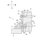
- FIG. 3 is a schematic side view showing a state in which the bolt hole of the counterweight is aligned with the female screw hole of the boss member.
- FIG. 3 is a schematic side view showing a state in which a bolt is screwed into a female screw hole of a boss member through a bolt hole of a counterweight.
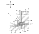
- FIG. 3 is a schematic side view showing a state in which the bolt is tightened and the boss member is drawn into the boss recess of the counterweight.
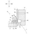
- FIG. 2 is a schematic side view showing a state in which the boss portion of the counterweight interferes with the support frame and requires readjustment in the prior art.
- FIG. 8 is a schematic diagram corresponding to FIG. 7 showing another example of the boss member in which the flange portion is omitted.
- FIG. 1 is a side view showing a hydraulic excavator according to the present embodiment, and first, the schematic configuration of the hydraulic excavator will be explained based on this figure. Note that in the following description, the front/rear, left/right, and up/down directions will be expressed based on the operator riding the hydraulic excavator.
- the lower traveling body 2 of the hydraulic excavator 1 is equipped with a pair of left and right crawlers 3, and the crawlers 3 are driven by a traveling hydraulic motor (not shown) to cause the hydraulic excavator 1 to travel.
- An upper revolving body 4 (corresponding to the "vehicle body" of the present invention) is provided on the lower traveling body 2, and the upper revolving body 4 is driven by a turning hydraulic motor (not shown) to rotate.
- An articulated work front 5 is provided at the front of the upper revolving body 4, and the work front 5 is composed of a boom 6, an arm 7, and a bucket 8. The angle of the boom 6 is changed by a boom cylinder 6a, the angle of the arm 7 is changed by an arm cylinder 7a, and the angle of the bucket 8 is changed by a bucket cylinder 8a.
- a driver's cab 10 is provided at the front of the frame 9 of the upper revolving structure 4, and various operating devices (not shown) provided in the driver's cab 10 are operated by an operator.
- a fuel tank 11, a machine room 12, a counterweight 13, etc. are provided on the rear side of the driver's cab 10 on the frame 9, and although not shown, inside the machine room 12 are an engine, a hydraulic pump driven by the engine, It is equipped with various equipment such as a hydraulic circuit that switches the hydraulic fluid discharged from the hydraulic pump. Hydraulic oil from the hydraulic pump is switched by a hydraulic circuit according to the operation of the operating device, and is supplied to the above-mentioned traveling and swinging hydraulic motors and each cylinder 6c to 8c of the work front 5. As a result, the hydraulic excavator 1 travels, the upper revolving structure 4 turns, the work front 5 operates, and the like.
- a pair of mounting bases 15 (one shown in FIGS. 2 and 3) is provided at the rear end of the frame 9 of the upper rotating body 4 at intervals in the left-right direction, and the hydraulic excavator 1 is A counterweight 13 is attached to the.
- a counterweight detaching device 16 for attaching and detaching the counterweight 13 is provided between each mounting base 15.
- the counterweight attachment/detachment device 16 has a configuration similar to that described in Patent Document 1, for example, in which a pair of left and right rotating arms are attached to a mounting base 15 at the rear of the frame 9 of the upper revolving body 4 of the hydraulic excavator 1 with a connecting pin.
- each rotating arm is pivoted, and the tip of each rotating arm is provided with a coupling that can be hooked to the hanging ring of the counterweight.
- Each rotating arm is driven by a lifting cylinder, and the mounting position is such that the tip is directed upward. and a detached position with the tip facing rearward.
- the present inventor prepared a boss member 18 which is a separate part from the counterweight 13 in place of the boss part 113a, and after placing the counterweight 13 on the mounting base 15, attached the boss member 18 to the counterweight 13.
- a countermeasure was found to arrange the boss member 18 between the base 15 and the base 15. The details will be explained below.
- FIG. 2 is a schematic side view showing a state in which the counterweight 13 has been installed
- FIG. 3 is a perspective view showing the boss member 18, the pedestal, and the fixing fittings
- FIG. 4 is a schematic diagram showing the boss member 18, the pedestal
- FIG. 3 is an exploded perspective view showing the fixing fittings.
- the mounting base 15 has a plate shape facing forward and backward, and its lower end is fixed to the rear end of the frame 9 of the upper revolving body 4 and extends upward.
- a pedestal 17 is fixed to the front side of the mounting base 15 on the frame 9, and the pedestal 17 has a guide surface 17a that is parallel to the axis of a boss hole 15a, which will be described later, faces upward, and has a rectangular shape in plan view. It consists of a side wall 17b and a front wall 17c formed on the left and right sides and the front side of the surface 17a, and the rear end of the pedestal 17 is in contact with the mounting base 15.
- a boss member 18 is disposed on the guide surface 17a of the pedestal 17, and the boss member 18 includes a rectangular parallelepiped-shaped insertion part 18a extending in the front-rear direction, and a square plate-shaped insertion part 18a integrally formed at the front end of the insertion part 18a. It consists of a flange portion 18b.
- the insertion portion 18a has a square shape (corresponding to the "square shape" of the present invention) when viewed from the rear.
- the entire lower surface of the boss member 18 abuts on the guide surface 17a, and the boss member 18 is movable in the front-rear direction while being guided by the guide surface 17a.
- the horizontal width of the insertion part 18a is set smaller than the horizontal width of the flange part 18b, and the vertical width of the insertion part 18a is set smaller than the vertical width of the flange part 18b. Therefore, when viewed from the rear, both left and right sides and an upper side of the insertion portion 18a are surrounded by the flange portion 18b, and hereinafter, this surrounding region of the flange portion 18b is referred to as a contact surface 18c.
- the fitting part 18a of the boss member 18 is provided with a fixing fitting 19 manufactured by bending a steel plate, which has a downwardly open concave shape corresponding to the cross-sectional shape of the fitting part 18a, and is inserted from above. It is fitted into the insertion part 18a. Both ends of the fixture 19 are fastened onto the guide surface 17a by bolts 20, and the boss member 18 is fixed onto the guide surface 17a by the fixture 19. When the counterweight 13 is removed from the hydraulic excavator 1 and transported, the fixture 19 is fastened to the base 17 and functions to prevent the boss member 18 from falling off.
- the fixing fitting 19 can be adopted as the fixing fitting 19 as long as the movement of the boss member 18 can be restricted.
- the boss member 18 may be pressed onto the guide surface 17a with the fixture 19 to restrict all movements in the front-rear direction, left-right direction, and upward direction.
- the movement in the left-right direction and upward is restricted by the fixing metal fitting 19
- the forward movement is restricted by the front wall 17c, and the abutment surface 18c of the flange portion 18b is brought into contact with the fixing metal fitting 19 for backward movement.
- FIG. 5 is a schematic diagram showing a state in which the bolt hole 13b of the counterweight 13 is aligned with the female screw hole 18d of the boss member 18, as seen from the side
- FIG. 7 is a schematic diagram showing the state in which the bolt is screwed into the female screw hole 18d of No. 18 when viewed from the side.
- FIG. It is a schematic diagram shown in a directional view.
- a boss hole 15a having a square shape (corresponding to the "square shape" of the present invention) corresponding to the insertion part 18a of the boss member 18 is provided through the mounting base 15.
- the lower wall inside 15a is flush with the guide surface 17a of the pedestal 17.
- the tip of the insertion portion 18a is moved backward from inside the boss hole 15a. It remains within the boss hole 15a without protruding.
- the boss member 18 moves rearward from this position, the insertion portion 18a protrudes rearward from within the boss hole 15a of the mounting base 15, as shown in FIG.
- the contact surface 18c of the flange portion 18b contacts the front surface of the mounting base 15, as shown in FIG. ).
- the counterweight 13 is disposed on the rear side of the mounting base 15, and has a square shape (corresponding to a "square shape” in the present invention) corresponding to the insertion portion 18a of the boss member 18 on its front surface. ) A boss recess 13a is formed.
- the configuration will be described below assuming that the counterweight 13 is attached to the mounting base 15 as shown in FIG.
- the boss member 18 is in the rear position, its contact surface 18c contacts the front surface of the mounting base 15, and the insertion portion 18a is inserted into the boss recess 13a from the front through the boss hole 15a of the mounting base 15. It has been inserted.
- a female thread 18d is formed from the rear in the insertion portion 18a of the boss member 18, and a bolt hole 13b is provided through the counterweight 13 in the front-rear direction so as to match the female thread 18d.
- a bolt 21 (corresponding to the "first fastening member" of the present invention) is inserted into the bolt hole 13b from the rear, and its tip is screwed into the female thread 18d of the boss member 18.
- the insertion portion 18a of the boss member 18 is drawn into the boss recess 13a of the counterweight 13 and fastened.
- the mounting base 15 is sandwiched between the contact surface 18c of the boss member 18 and the front surface of the counterweight 13, and the counterweight 13 is attached to the mounting base 15.
- the vertical width of the boss hole 15a of the mounting base 15 and the vertical width of the boss recess 13a of the counterweight 13 are smaller than the vertical width of the insertion portion 18a of the boss member 18. They are set slightly larger, and a vertical gap is formed between them.
- the horizontal width of the boss hole 15a of the mounting base 15 and the horizontal width of the boss recess 13a of the counterweight 13 are also set to be slightly larger than the horizontal width of the insertion portion 18a.
- the present invention is not limited to this, and the vertical widths of the members 18a, 15a, and 13a may be made to match, or the left and right widths may be made to be made to match.
- bolt holes 13c and 15b are formed through the counterweight 13 and the mounting base 15 in the front and back direction, respectively, and bolts 22 (corresponding to the "second fastening member” of the present invention) are inserted from the rear. ) are inserted into the bolt holes 13c and 15b and are screwed into nuts 23 welded to the front surface of the mounting base 15. As a result, the mounting base 15 and the counterweight 13 are also fastened at this position.
- the counterweight 13 configured as described above is detached by the counterweight detachment device 16.
- the bolts 21 and 22 are unfastened.
- the counterweight 13 Since the counterweight 13 is removed following an arcuate trajectory L centered on the connecting pin, its movement may be blocked by the boss member 18 at the rear position. Therefore, for example, the removed bolt 21 is inserted into the bolt hole 13b of the counterweight 13, and its tip pushes the boss member 18 to move it to the forward position. Then, when the rotating arm of the counterweight attachment/detachment device 16 is rotated to the removal position, the counterweight 13 is moved and placed on the ground surface.
- the rotating arm of the counterweight attachment/detachment device 16 is set to the detached position, and the approximate hanging height of the counterweight 13 is adjusted using the adjustment bolts of each connector, and then the counterweight 13 is hooked to the hanging ring.
- the counterweight 13 is suspended and moves to the mounting base 15 following an arcuate trajectory L, as shown in FIG.
- the vertical positional relationship between the fitting portion 18a of the boss member 18 and the boss recess 13a of the counterweight 13 (and the vertical positional relationship between the female screw 18d and the bolt hole 13b) changes as the counterweight 13 moves. It changes gradually.
- the insertion portion 18a and the boss recess 13a will be vertically aligned. Match.
- the worker looks into the bolt hole 13b of the counterweight 13 from behind, checks the positional relationship between the bolt hole 13b and the female thread 18d of the boss member 18, and stops moving the counterweight 13 when they match. .
- the bolt 21 is inserted into the bolt hole 13b of the counterweight 13 from the rear, and its tip is screwed into the female thread 18d of the boss member 18, and temporarily tightened.
- the boss member 18 at the front position moves to the rear position while being guided by the guide surface 17a, and as shown in FIG. It is drawn into the boss recess 13a.
- the contact surface 18c of the boss member 18 contacts the front surface of the mounting base 15, and the front surface of the counterweight 13 contacts the rear surface of the mounting base 15.
- the bolt 22 is inserted from the rear into the bolt holes 13c and 15b of the counterweight 13 and the mounting base 15, and its tip is screwed into the nut 23 and temporarily tightened.
- the weight of the counterweight 13 acts on the boss member 18 and comes to be supported by the mounting base 15 via the boss member 18.
- the bolts 21 and 22 are fully tightened, the counterweight 13 is attached to the attachment base 15, and a series of attachment operations is completed.
- the boss member 18 is a separate part from the counterweight 13, so that the front surface of the boss member 18 is different from that of the counterweight 113 of the prior art shown in FIG. 8, for example.
- the boss portion 113a does not protrude and has a flat shape. 5 and 8 show the case where the respective counterweights 13 and 113 are adjusted to the same hanging height.
- the boss portion 113a protruding forward is inserted into the boss hole 115a. This interferes with the mounting base 115 and prevents the counterweight 113 from moving. Therefore, readjustment is required to readjust the hanging height upward.
- the arcuate trajectory L is moved to the vertical position where the boss recess 13a matches the insertion portion 18a of the boss member 18.
- the counterweight 13 can be moved without any problem. After aligning the fitting part 18a and the boss recess 13a, if the fitting part 18a of the boss member 18 is pulled into the boss recess 13a by screwing the bolt 21, the counterweight 13 is inserted through the boss member 18. can be supported by the mounting base 15. As a result, the adjustment allowance for the lifting height can be expanded downward by an amount corresponding to the dimension A in FIG. 8, which reduces the chances of needing readjustment, making it easier to install the counterweight 13. I can do it.
- the vertical width of the boss recess 13a of the counterweight 13 is set to be larger than the vertical width of the insertion part 18a of the boss member 18, so that a vertical gap is formed between them. . Therefore, even if the hanging height is slightly shifted upward, the fitting portion 18a can be inserted into the boss recess 13a. As a result, in this case, there is no need to readjust the suspension height downward, which also greatly contributes to easing the installation work.
- the bolt 21 is screwed into the female thread 18d of the boss member 18 from the rear through the bolt hole 13b of the counterweight 13.
- the fitting portion 18a of the boss member 18 is drawn into the boss recess 13a of the counterweight 13, and the mounting base 15 is sandwiched between the contact surface of the boss member 18 and the front surface of the counterweight 13.
- the counterweight 13 can be fastened to the mounting base 15 simply by screwing the bolt 21 into the boss member 18 from the rear.
- a pedestal 17 is fixed to the front side of the mounting base 15 on the frame 9, and a boss member 18 is disposed on an upwardly facing guide surface 17a formed on the pedestal 17 to guide movement in the front-rear direction. If the configuration does not include the pedestal 17, an operator would hold the boss member 18, which is a heavy object, and manually insert the fitting part 18a from the front side of the mounting base 15 through the boss hole 15a. It is necessary to insert it into the boss recess 13a of the counterweight 13. However, since the boss member 18 is guided on the guide surface 17a, such labor-intensive work can be significantly reduced. In addition, the boss member 18 can be drawn into the boss recess 13a of the counterweight 13 by simply screwing and tightening the bolt 21 onto the boss member 18 from the rear.
- the bolt 22 is simply screwed into the nut 23 from the rear through the bolt holes 13c and 15b of the counterweight 13 and the mounting base 15, and with such a simple operation, the counterweight 13 is attached to the mounting base 15. The conclusion of the contract is completed.
- a machine room 12 is defined on the front side of the mounting base 15 on the frame 9, and a maintenance opening (not shown) is formed downward in the frame 9 for maintenance of the machine room 12. Therefore, the worker puts his upper body into the machine room 12 through the maintenance opening and performs the above-described tightening operation of the bolt 122 (shown in FIG. 8) or the operation of inserting the boss member 18 (shown in FIG. 7). I will do it. However, at this time, the worker continues to maintain a half-slumped posture and works while avoiding various devices in the machine room 12 that may be obstacles, making the work extremely complicated.
- the operator only has to fasten the bolts 21 and 22 at the rear position of the revolving upper structure 4, and the operator can perform this work in an upright natural posture, and can also use the counterweight 13.
- the work is extremely simple, and this greatly contributes to the ease of the entire installation work of the counterweight 13.
- the insertion portion 18a of the boss member 18 has a square shape when viewed from the rear, and corresponding to the shape of the boss member 18, the boss hole 15a of the mounting base 15 and the boss recess 13a of the counterweight 13 have a square shape. Because of this, relative rotation is restricted. A rotational force acts on the boss member 18 when the bolt 21 is fastened, but since the rotation of the boss member 18 at this time is regulated by the boss hole 15a of the mounting base 15 and the boss recess 13a of the counterweight 13, the bolt 21 can be easily tightened. This also greatly contributes to the ease of installation work.
- both the boss hole 15a of the mounting base 15 and the boss recess 13a of the counterweight 13 have a square shape. If one of the members 15a, 13a is made into a square shape, the rotation of the boss member 18 can be restricted, and the other member may have another shape into which the insertion portion 18a can be inserted. Further, the shape of each member 18a, 15a, 13a is not limited to a rectangular shape when viewed from the rear, and may be changed to other shapes that can restrict rotation. Furthermore, it is not necessarily necessary to restrict the rotation, and it may be circular, for example, and such a case is also included in the present invention.
- the mounting structure is applied to the counterweight 13 of the hydraulic excavator 1, but the present invention is not limited to this.
- the present invention can be applied to various working machines to which a counterweight is detachably attached, and may be embodied as a counterweight attachment structure for a hydraulic crane, for example.
- the bolt 21 is inserted into the bolt hole 13b of the counterweight 13 from the rear to fasten the boss member 18 within the boss recess 13a, but the present invention is not limited to this.
- a bolt hole is provided in the boss member 18 in the front-rear direction
- a female thread is formed in the boss recess 13a of the counterweight 13 corresponding to the bolt hole, and the bolt is inserted from the front through the bolt hole of the boss member 18.
- it may be screwed into a female screw in the boss recess 13a.
- the flange portion 18b is formed on the boss member 18, but the flange portion 18b may be omitted, for example, as shown in FIG. 9.
- the bolt 21 no longer plays the role of fastening the counterweight 13 to the mounting base 15, but since this fastening function is performed by the bolt 22 and nut 23, no problem occurs.
- the pedestal 17 is fixed on the frame 9 to guide the movement of the boss member 18, but the pedestal 17 may be omitted.
- the lower surface of the boss member 18 is made flat with the assumption that it will be placed on the guide surface 17a, but since this is no longer necessary, the flange portion 18b is extended not only to the left and right sides and the upper side but also to the lower side.
- the contact surface 18c may also be made to function as the contact surface 18c.
Landscapes
- Engineering & Computer Science (AREA)
- Mining & Mineral Resources (AREA)
- Civil Engineering (AREA)
- General Engineering & Computer Science (AREA)
- Structural Engineering (AREA)
- Mechanical Engineering (AREA)
- Component Parts Of Construction Machinery (AREA)
Priority Applications (4)
| Application Number | Priority Date | Filing Date | Title |
|---|---|---|---|
| US18/689,461 US20240376689A1 (en) | 2022-03-23 | 2023-03-23 | Work machine |
| JP2024509196A JP7547686B2 (ja) | 2022-03-23 | 2023-03-23 | 作業機 |
| CN202380013414.5A CN117897536A (zh) | 2022-03-23 | 2023-03-23 | 作业机 |
| EP23775000.5A EP4379147A4 (en) | 2022-03-23 | 2023-03-23 | WORKING MACHINE |
Applications Claiming Priority (2)
| Application Number | Priority Date | Filing Date | Title |
|---|---|---|---|
| JP2022-046570 | 2022-03-23 | ||
| JP2022046570 | 2022-03-23 |
Publications (1)
| Publication Number | Publication Date |
|---|---|
| WO2023182406A1 true WO2023182406A1 (ja) | 2023-09-28 |
Family
ID=88101628
Family Applications (1)
| Application Number | Title | Priority Date | Filing Date |
|---|---|---|---|
| PCT/JP2023/011401 Ceased WO2023182406A1 (ja) | 2022-03-23 | 2023-03-23 | 作業機 |
Country Status (5)
| Country | Link |
|---|---|
| US (1) | US20240376689A1 (https=) |
| EP (1) | EP4379147A4 (https=) |
| JP (1) | JP7547686B2 (https=) |
| CN (1) | CN117897536A (https=) |
| WO (1) | WO2023182406A1 (https=) |
Families Citing this family (1)
| Publication number | Priority date | Publication date | Assignee | Title |
|---|---|---|---|---|
| JP7398422B2 (ja) * | 2021-12-03 | 2023-12-14 | 株式会社小松製作所 | 作業機械 |
Citations (4)
| Publication number | Priority date | Publication date | Assignee | Title |
|---|---|---|---|---|
| JPH0165356U (https=) * | 1987-10-19 | 1989-04-26 | ||
| JPH0633485A (ja) * | 1992-07-17 | 1994-02-08 | Hitachi Constr Mach Co Ltd | 作業機 |
| JPH07268908A (ja) | 1994-03-29 | 1995-10-17 | Hitachi Constr Mach Co Ltd | 作業機のカウンタウエイト脱着装置 |
| JPH09124285A (ja) * | 1995-10-27 | 1997-05-13 | Mitsubishi Heavy Ind Ltd | 産業機械のウエイト着脱装置 |
Family Cites Families (18)
| Publication number | Priority date | Publication date | Assignee | Title |
|---|---|---|---|---|
| US4072324A (en) * | 1976-08-19 | 1978-02-07 | Caterpillar Tractor Co. | Shear pin assembly for counterweights |
| JPH0163356U (https=) * | 1987-10-15 | 1989-04-24 | ||
| JP2797790B2 (ja) * | 1991-11-20 | 1998-09-17 | 日産自動車株式会社 | 産業車両用カウンタウエイトの取付構造 |
| JPH0655966U (ja) * | 1993-01-19 | 1994-08-02 | 日立建機株式会社 | 建設機械等におけるカウンタウエイトの取り付け装置 |
| JPH09209407A (ja) * | 1996-02-06 | 1997-08-12 | Yutani Heavy Ind Ltd | カウンタウエイトの取付方法 |
| JP5449264B2 (ja) * | 2011-06-30 | 2014-03-19 | 日立建機株式会社 | カウンタウエイト脱着装置用油圧回路 |
| CN202370028U (zh) * | 2011-11-01 | 2012-08-08 | 三一重机有限公司 | 一种挖掘机及其配重定位结构 |
| JP2015059343A (ja) * | 2013-09-19 | 2015-03-30 | コベルコ建機株式会社 | 作業機械 |
| WO2016072975A1 (en) * | 2014-11-04 | 2016-05-12 | Volvo Construction Equipment Ab | Push block module for front end of motor graders |
| JP6497978B2 (ja) * | 2015-03-02 | 2019-04-10 | キャタピラー エス エー アール エル | カウンタウェイトの移動装置 |
| JP6497736B2 (ja) * | 2015-06-18 | 2019-04-10 | キャタピラー エス エー アール エル | 建設機械におけるカウンタウエイト支持構造 |
| JP6497737B2 (ja) * | 2015-06-18 | 2019-04-10 | キャタピラー エス エー アール エル | 建設機械におけるカウンタウエイト支持構造 |
| CN210887394U (zh) * | 2019-09-16 | 2020-06-30 | 江苏蓝力重工科技有限公司 | 具有回转快速平稳功能的挖掘机配重机构 |
| JP7167077B2 (ja) * | 2020-03-16 | 2022-11-08 | 日立建機株式会社 | 作業機械 |
| JP2021147994A (ja) * | 2020-03-16 | 2021-09-27 | 日立建機株式会社 | 作業機械 |
| JP7167076B2 (ja) * | 2020-03-16 | 2022-11-08 | 日立建機株式会社 | 作業機械 |
| JP7374031B2 (ja) * | 2020-03-23 | 2023-11-06 | 日立建機株式会社 | 作業機械 |
| CN212926240U (zh) * | 2020-05-10 | 2021-04-09 | 杭州富阳保利铸造有限公司 | 一种挖掘机配重的固定支架 |
-
2023
- 2023-03-23 JP JP2024509196A patent/JP7547686B2/ja active Active
- 2023-03-23 CN CN202380013414.5A patent/CN117897536A/zh active Pending
- 2023-03-23 WO PCT/JP2023/011401 patent/WO2023182406A1/ja not_active Ceased
- 2023-03-23 US US18/689,461 patent/US20240376689A1/en active Pending
- 2023-03-23 EP EP23775000.5A patent/EP4379147A4/en active Pending
Patent Citations (4)
| Publication number | Priority date | Publication date | Assignee | Title |
|---|---|---|---|---|
| JPH0165356U (https=) * | 1987-10-19 | 1989-04-26 | ||
| JPH0633485A (ja) * | 1992-07-17 | 1994-02-08 | Hitachi Constr Mach Co Ltd | 作業機 |
| JPH07268908A (ja) | 1994-03-29 | 1995-10-17 | Hitachi Constr Mach Co Ltd | 作業機のカウンタウエイト脱着装置 |
| JPH09124285A (ja) * | 1995-10-27 | 1997-05-13 | Mitsubishi Heavy Ind Ltd | 産業機械のウエイト着脱装置 |
Non-Patent Citations (1)
| Title |
|---|
| See also references of EP4379147A4 |
Also Published As
| Publication number | Publication date |
|---|---|
| CN117897536A (zh) | 2024-04-16 |
| EP4379147A1 (en) | 2024-06-05 |
| JPWO2023182406A1 (https=) | 2023-09-28 |
| EP4379147A4 (en) | 2025-08-06 |
| JP7547686B2 (ja) | 2024-09-09 |
| US20240376689A1 (en) | 2024-11-14 |
Similar Documents
| Publication | Publication Date | Title |
|---|---|---|
| US6499934B1 (en) | Implement attachment bracket for skid steer loader mounting plate | |
| US9617706B2 (en) | Working machine with hydraulic hose and boom intermediate portion | |
| JP2674712B2 (ja) | 関節式の連結構造を有するクレーン型機械 | |
| US9945093B1 (en) | Excavator, excavator boom, stick object coupler receiver for the same and method of using the same | |
| EP1124017B1 (en) | Hydraulically driven working machine | |
| WO2023182406A1 (ja) | 作業機 | |
| JP6829635B2 (ja) | バッテリ取付構造 | |
| US20210404144A1 (en) | Front guard and working machine | |
| JP5053212B2 (ja) | ローダ作業機のエンジン設置構造 | |
| EP2045400A1 (en) | Apparatus for fixing hydraulic pipes for zero tail swing excavator | |
| JP6982591B2 (ja) | 建設機械 | |
| JP7636240B2 (ja) | 建設機械 | |
| JP4260687B2 (ja) | 旋回作業機 | |
| JP3939883B2 (ja) | 旋回式建設機械 | |
| JP4543407B2 (ja) | 振動式杭打抜機 | |
| JP2000248752A (ja) | 建設機械のアームへのクランプ式バケットの取付け装置 | |
| JP4845206B2 (ja) | 建設機械のアンダーカバー装置 | |
| JP2010106529A (ja) | 建設機械の油圧ホースの固定装置 | |
| JP2006274589A (ja) | 建設機械のエンドアタッチメント装着装置 | |
| JP4236645B2 (ja) | 旋回作業機におけるロータリジョイントの取付構造 | |
| JPH1018336A (ja) | 作業機アタッチメントの簡易着脱装置 | |
| JP2021021189A (ja) | 建設機械 | |
| JP7608998B2 (ja) | アダプタおよび上部旋回体 | |
| JP3462639B2 (ja) | 建設土木機械における先端工具の簡易油圧駆動装置 | |
| JP6760909B2 (ja) | 建設機械 |
Legal Events
| Date | Code | Title | Description |
|---|---|---|---|
| 121 | Ep: the epo has been informed by wipo that ep was designated in this application |
Ref document number: 23775000 Country of ref document: EP Kind code of ref document: A1 |
|
| WWE | Wipo information: entry into national phase |
Ref document number: 2024509196 Country of ref document: JP |
|
| WWE | Wipo information: entry into national phase |
Ref document number: 2023775000 Country of ref document: EP |
|
| WWE | Wipo information: entry into national phase |
Ref document number: 202380013414.5 Country of ref document: CN |
|
| ENP | Entry into the national phase |
Ref document number: 2023775000 Country of ref document: EP Effective date: 20240226 |
|
| WWE | Wipo information: entry into national phase |
Ref document number: 18689461 Country of ref document: US |
|
| NENP | Non-entry into the national phase |
Ref country code: DE |