WO2023175966A1 - 車両走行制御方法及び車両走行制御装置 - Google Patents
車両走行制御方法及び車両走行制御装置 Download PDFInfo
- Publication number
- WO2023175966A1 WO2023175966A1 PCT/JP2022/012837 JP2022012837W WO2023175966A1 WO 2023175966 A1 WO2023175966 A1 WO 2023175966A1 JP 2022012837 W JP2022012837 W JP 2022012837W WO 2023175966 A1 WO2023175966 A1 WO 2023175966A1
- Authority
- WO
- WIPO (PCT)
- Prior art keywords
- lane
- trajectory
- vehicle
- link
- road
- Prior art date
- Legal status (The legal status is an assumption and is not a legal conclusion. Google has not performed a legal analysis and makes no representation as to the accuracy of the status listed.)
- Ceased
Links
Images



Classifications
-
- B—PERFORMING OPERATIONS; TRANSPORTING
- B60—VEHICLES IN GENERAL
- B60W—CONJOINT CONTROL OF VEHICLE SUB-UNITS OF DIFFERENT TYPE OR DIFFERENT FUNCTION; CONTROL SYSTEMS SPECIALLY ADAPTED FOR HYBRID VEHICLES; ROAD VEHICLE DRIVE CONTROL SYSTEMS FOR PURPOSES NOT RELATED TO THE CONTROL OF A PARTICULAR SUB-UNIT
- B60W30/00—Purposes of road vehicle drive control systems not related to the control of a particular sub-unit, e.g. of systems using conjoint control of vehicle sub-units
- B60W30/10—Path keeping
- B60W30/12—Lane keeping
-
- B—PERFORMING OPERATIONS; TRANSPORTING
- B60—VEHICLES IN GENERAL
- B60W—CONJOINT CONTROL OF VEHICLE SUB-UNITS OF DIFFERENT TYPE OR DIFFERENT FUNCTION; CONTROL SYSTEMS SPECIALLY ADAPTED FOR HYBRID VEHICLES; ROAD VEHICLE DRIVE CONTROL SYSTEMS FOR PURPOSES NOT RELATED TO THE CONTROL OF A PARTICULAR SUB-UNIT
- B60W60/00—Drive control systems specially adapted for autonomous road vehicles
- B60W60/001—Planning or execution of driving tasks
- B60W60/0013—Planning or execution of driving tasks specially adapted for occupant comfort
-
- B—PERFORMING OPERATIONS; TRANSPORTING
- B60—VEHICLES IN GENERAL
- B60W—CONJOINT CONTROL OF VEHICLE SUB-UNITS OF DIFFERENT TYPE OR DIFFERENT FUNCTION; CONTROL SYSTEMS SPECIALLY ADAPTED FOR HYBRID VEHICLES; ROAD VEHICLE DRIVE CONTROL SYSTEMS FOR PURPOSES NOT RELATED TO THE CONTROL OF A PARTICULAR SUB-UNIT
- B60W2552/00—Input parameters relating to infrastructure
- B60W2552/20—Road profile, i.e. the change in elevation or curvature of a plurality of continuous road segments
-
- B—PERFORMING OPERATIONS; TRANSPORTING
- B60—VEHICLES IN GENERAL
- B60W—CONJOINT CONTROL OF VEHICLE SUB-UNITS OF DIFFERENT TYPE OR DIFFERENT FUNCTION; CONTROL SYSTEMS SPECIALLY ADAPTED FOR HYBRID VEHICLES; ROAD VEHICLE DRIVE CONTROL SYSTEMS FOR PURPOSES NOT RELATED TO THE CONTROL OF A PARTICULAR SUB-UNIT
- B60W2552/00—Input parameters relating to infrastructure
- B60W2552/30—Road curve radius
-
- B—PERFORMING OPERATIONS; TRANSPORTING
- B60—VEHICLES IN GENERAL
- B60W—CONJOINT CONTROL OF VEHICLE SUB-UNITS OF DIFFERENT TYPE OR DIFFERENT FUNCTION; CONTROL SYSTEMS SPECIALLY ADAPTED FOR HYBRID VEHICLES; ROAD VEHICLE DRIVE CONTROL SYSTEMS FOR PURPOSES NOT RELATED TO THE CONTROL OF A PARTICULAR SUB-UNIT
- B60W2552/00—Input parameters relating to infrastructure
- B60W2552/53—Road markings, e.g. lane marker or crosswalk
-
- B—PERFORMING OPERATIONS; TRANSPORTING
- B60—VEHICLES IN GENERAL
- B60W—CONJOINT CONTROL OF VEHICLE SUB-UNITS OF DIFFERENT TYPE OR DIFFERENT FUNCTION; CONTROL SYSTEMS SPECIALLY ADAPTED FOR HYBRID VEHICLES; ROAD VEHICLE DRIVE CONTROL SYSTEMS FOR PURPOSES NOT RELATED TO THE CONTROL OF A PARTICULAR SUB-UNIT
- B60W2556/00—Input parameters relating to data
- B60W2556/40—High definition maps
-
- G—PHYSICS
- G01—MEASURING; TESTING
- G01C—MEASURING DISTANCES, LEVELS OR BEARINGS; SURVEYING; NAVIGATION; GYROSCOPIC INSTRUMENTS; PHOTOGRAMMETRY OR VIDEOGRAMMETRY
- G01C21/00—Navigation; Navigational instruments not provided for in groups G01C1/00 - G01C19/00
- G01C21/26—Navigation; Navigational instruments not provided for in groups G01C1/00 - G01C19/00 specially adapted for navigation in a road network
- G01C21/34—Route searching; Route guidance
- G01C21/3407—Route searching; Route guidance specially adapted for specific applications
Definitions
- the present invention relates to a vehicle travel control method and a vehicle travel control device.
- Patent Document 1 listed below describes a technology for estimating the center line of a lane using sensor information from a camera, etc., and navigating an autonomous vehicle along the lowest cost route generated based on the center line. There is.
- An object of the present invention is to suppress the discomfort of occupants when a vehicle traveling from a first road to a second road branching from a first road is controlled by automatic steering based on map information representing the lane shape using nodes and links. shall be.
- a vehicle travel control method in which a vehicle is caused to travel along a lane by automatic steering based on map information representing a lane shape using nodes and links.
- the vehicle travel control method includes a process of determining whether or not a target travel route of a vehicle traveling on a first road is a route leading to a second road that branches from the first road in front of the vehicle; is a route to a second road, from the first link, which is a link representing the lane shape of the first lane on the first road, to the second link, which is a link representing the lane shape of the second lane, on the second road.
- a first trajectory is calculated that connects the branching point where the vehicle branches, and a point on the second link that is a predetermined distance away from the branching point along the second link, and a target travel trajectory is set based on the first trajectory.
- the controller is caused to execute the process and the process of controlling the vehicle to travel along the target travel trajectory.
- FIG. 1 is a diagram illustrating an example of a schematic configuration of a vehicle equipped with a driving support device according to an embodiment.
- 2 is an explanatory diagram of high-precision map information stored in the map database of FIG. 1.
- FIG. 2 is a diagram showing a part of the input device of FIG. 1.
- FIG. 2 is an explanatory diagram of an example of a vehicle travel control method according to an embodiment.
- FIG. 2 is a block diagram of an example of the functional configuration of the controller in FIG. 1.
- FIG. FIG. 3 is an explanatory diagram of an example of correction of a shortcut trajectory. It is an explanatory view of an example when a shortcut trajectory is not used.
- 3 is a flowchart of an example of a vehicle travel control method according to an embodiment.
- FIG. 1 is a diagram showing an example of a schematic configuration of a vehicle equipped with a driving support device according to an embodiment.
- the driving support device 10 mounted on the own vehicle 1 includes a sensor 11 , a positioning device 12 , a map database (map DB) 13 , an on-vehicle device 14 , a navigation system 15 , a display device 16 , and an audio output device 17 , an input device 18 , a vehicle behavior control device 19 , and a controller 20 .
- These devices are connected by, for example, a CAN (Controller Area Network) or other in-vehicle LAN in order to mutually transmit and receive information.
- the driving support device 10 is an example of a "vehicle travel control device" described in the claims.
- the sensor 11 detects the running state of the own vehicle 1.
- the sensor 11 includes cameras that take images of the front, rear, and sides of the own vehicle 1, respectively.
- the sensor 11 includes a radar that detects obstacles in front of, behind, and on the sides of the host vehicle 1, respectively.
- the sensor 11 includes a vehicle speed sensor that detects the speed of the own vehicle 1, a touch sensor that detects whether the occupant is holding the steering wheel, an occupant monitor that captures an image of the occupant, and the like.
- the positioning device 12 includes a GPS unit, a gyro sensor, and the like. The positioning device 12 periodically acquires position information of the own vehicle 1 using a GPS unit. Furthermore, the positioning device 12 detects the current position of the own vehicle 1 based on the position information of the own vehicle 1, the angle change information obtained from the gyro sensor, and the vehicle speed obtained from the vehicle speed sensor.
- the map database 13 is a memory that stores high-precision map information including position information of various facilities and specific points, and is accessible from the controller 20.
- High-precision map information includes map information as well as detailed and high-precision locations such as curved roads and the size of their curves (e.g. curvature or radius of curvature), road merging points, branching points, toll plazas, and locations where the number of lanes is reduced.
- the information is map information associated as three-dimensional information.
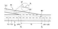
- FIG. 2 is an explanatory diagram of high-precision map information stored in the map database 13 of FIG. 1.
- the high-precision map information includes node information indicating a reference point on a lane reference line (for example, the center line within a lane) and the mode of lane sections between lane nodes, as information for each lane (i.e., lane information).
- a link information indicating a reference point on a lane reference line (for example, the center line within a lane) and the mode of lane sections between lane nodes, as information for each lane (i.e., lane information).
- the second road R2 is a road that branches from the first road R1, and the section from the starting point Ps where the second road R2 starts branching from the first road R1 to the completion point Pe where the branching is completed is referred to as a "branching section". It is written as "Sj".
- the first road R1 may be the main line of a motorway such as an expressway
- the second road R2 may be a branch road branching from the main road.
- the high-precision map information includes a node ND1 and links LK11, LK12, LK2, and LK3, each represented by a broken line, as information representing the lane shapes of the first road R1 and the second road R2.
- link LK11 will be referred to as “first link LK11”
- link LK12 will be referred to as “first link LK12”
- link LK2 will be referred to as "second link LK2.”
- Each link is formed by a point sequence PL in which link constituent points CP representing reference points on a lane reference line (for example, a center line within a lane) are arranged. Therefore, the point sequence PL of the link constituent points CP can express not only a straight link but also a curved link.
- the first links LK11 and LK12 represent the lane shape of the first lane TL1 by indicating the lane center line of the first lane TL1 of the first road R1.
- the link LK3 represents the lane shape of the lane TL3 by indicating the lane center line of the lane TL3 on the first road R1.
- the second link LK2 represents the lane shape of the second lane TL2 by indicating the lane center line of the second lane TL2 of the second road R2. Then, by connecting the second link LK2 to the node ND1 to which the first links LK11 and LK12 are connected, the second lane TL2 of the second road branching from the first road R1 becomes the first lane TL2 of the first road R1.
- a shape connected to lane TL1 is expressed.
- the on-vehicle equipment 14 is various types of equipment mounted on the own vehicle 1, and is operated by an operation by a passenger (for example, a driver).
- Such in-vehicle devices include steering wheels, accelerator pedals, brake pedals, turn signals, wipers, lights, horns, and other specific switches.
- the navigation system 15 acquires current position information of the own vehicle 1 from the positioning device 12, superimposes the position of the own vehicle 1 on navigation map information, and displays the superimposed position on a display or the like. Further, when a destination is set, the navigation system 15 sets a route from the current position of the host vehicle 1 to the destination as a target travel route, and executes navigation control to guide the occupant to the target travel route.
- the navigation system 15 displays the target travel route on a map on the display and informs the occupant of the target travel route by voice or the like.
- the target travel route set by the navigation system 15 is also used in route travel support control by the controller 20.
- Route travel support control is control that causes the host vehicle 1 to travel autonomously along a target travel route.
- the display device 16 includes various displays provided at positions visible to the occupant.
- the display device 16 notifies the occupant of various types of presentation information under the control of the controller 20 .
- the audio output device 17 is a device that outputs auditory information, such as a speaker included in the navigation system 15, a speaker of an audio device, or a buzzer.
- the audio output device 17 notifies the occupant of various presentation information under the control of the controller 20 .
- the input device 18 is, for example, a button switch that allows manual input by the passenger, a touch panel placed on a display screen, or a microphone that allows the passenger to input by voice. By operating the input device 18, the occupant can input setting information for presentation information presented by the display device 16 and the audio output device 17.
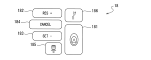
- FIG. 3 is a diagram showing a part of the input device 18 of this embodiment.
- the input device 18 may be, for example, a group of button switches arranged on a spoke part of a steering wheel.
- the input device 18 is used to turn on/off the autonomous driving control by the controller 20, etc.
- the input device 18 includes a main switch 181, a resume/accelerate switch 182, a set/coast switch 183, a cancel switch 184, a distance adjustment switch 185, and a lane change assist switch 186.
- the main switch 181 is a switch that turns on/off autonomous driving control of the controller 20.
- the resume/accelerate switch 182 is a switch that sets the autonomous driving control to be restarted at the set speed before turning off after the autonomous driving control is turned off, or to increase the set speed.
- the set/coast switch 183 is a switch that starts autonomous driving control. To start the autonomous running control, after turning on the autonomous running control using the main switch 181, the set/coast switch 183 is pressed. Further, the set/coast switch 183 is a switch that lowers the set speed.
- the cancel switch 184 is a switch that cancels autonomous driving control.
- the inter-vehicle distance adjustment switch 185 is a switch for setting the inter-vehicle distance to the preceding vehicle.
- the lane change support switch 186 is a switch for instructing (approving) the start of a lane change when the controller 20 confirms with the occupant that the lane change has started.
- a direction indicator lever of a direction indicator or a switch of other in-vehicle equipment 14 can be used as the input device 18.
- the vehicle behavior control device 19 controls the vehicle behavior of the host vehicle 1 .
- the vehicle behavior control device 19 controls the drive to realize acceleration/deceleration and running speed so that the own vehicle 1 reaches the set speed. Controls mechanism operation and brake operation. Further, the vehicle behavior control device 19 similarly controls the operation of the drive mechanism and the brakes even when the own vehicle 1 follows a preceding vehicle by autonomous running control.
- the operation control of the drive mechanism includes the operation of the internal combustion engine in the case of an engine vehicle, and the operation of the travel motor in the case of an electric vehicle. In the case of a hybrid vehicle, this also includes torque distribution between the internal combustion engine and the driving motor.
- autonomous steering control described later
- autonomous running control controls the steering of the host vehicle 1 by controlling the operation of the steering actuator in addition to controlling the operation of the drive mechanism and brakes. Execute.
- the controller 20 is one or more electronic control units (ECUs) for controlling the running of the host vehicle 1, and includes a processor 21 and peripheral components such as a storage device 22.
- the processor 21 may be, for example, a CPU or an MPU.
- the storage device 22 may include a semiconductor storage device, a magnetic storage device, an optical storage device, or the like.
- the storage device 22 may include memory such as registers, cache memory, ROM and RAM used as main storage.
- the functions of the controller 20 described below are realized, for example, by the processor 21 executing a computer program stored in the storage device 22.
- the controller 20 realizes a driving information acquisition function that acquires information regarding the driving state of the own vehicle 1, and executes autonomous driving control that autonomously controls the traveling speed and/or steering of the own vehicle 1.
- the driving information acquisition function is a function of acquiring driving information regarding the driving state of the own vehicle 1.
- the controller 20 also acquires, as driving information, image information of the exterior of the vehicle captured by the camera of the sensor 11, detection results by a radar, and vehicle speed information from a vehicle speed sensor.
- the driving information acquired from the sensor 11 may be referred to as "sensor information”.
- the controller 20 acquires current position information of the own vehicle 1 from the positioning device 12 as driving information.
- the controller 20 acquires the set destination and the target travel route to the destination from the navigation system 15 as travel information.
- the controller 20 provides travel information such as curved roads and the size of the curve (for example, curvature or radius of curvature), location information such as merging points, branching points, toll plazas, positions where the number of lanes is reduced, and map information such as lane information. is obtained from the map database 13.
- the controller 20 acquires operation information of the vehicle-mounted device 14 by the occupant from the vehicle-mounted device 14 as driving information.
- the autonomous driving control the controller 20 autonomously controls the driving of the own vehicle 1 without depending on the operation of the occupant.
- the autonomous running control includes autonomous speed control that autonomously controls the traveling speed of the own vehicle 1 and autonomous steering control that autonomously controls the steering of the own vehicle 1.
- autonomous speed control when a preceding vehicle is detected, the controller 20 follows the preceding vehicle while controlling the inter-vehicle distance to maintain an inter-vehicle distance according to the vehicle speed, with the vehicle speed or speed limit set by the occupant as the upper limit. Run. On the other hand, if no preceding vehicle is detected, the vehicle continues to drive at a constant speed or speed limit set by the occupant.
- the former is also called distance control, and the latter is also called constant speed control.
- the constant speed control is executed when the forward radar of the sensor 11 or the like detects that there is no preceding vehicle in front of the lane in which the host vehicle 1 is traveling.
- the vehicle behavior control device 19 controls the operation of drive mechanisms such as the engine and brakes while feeding back vehicle speed data from a vehicle speed sensor so as to maintain a set running speed.
- the inter-vehicle distance control is executed when the forward radar of the sensor 11 or the like detects that a preceding vehicle is present in front of the lane in which the own vehicle 1 is traveling.
- the vehicle behavior control device 19 drives the engine, brakes, etc. while feeding back inter-vehicle distance data detected by the forward radar so as to maintain the set inter-vehicle distance with the set traveling speed as the upper limit. Control the operation of the mechanism.
- the controller 20 performs steering control of the host vehicle 1 by controlling the operation of the steering actuator based on the driving information acquired by the driving information acquisition function.
- the autonomous steering control includes lane keeping control, lane change support control, overtaking support control, and route driving support control.
- lane keep control the controller 20 supports the steering operation of the occupant by controlling the steering actuator so that the vehicle travels near the center of the lane, for example.
- the controller 20 turns on the direction indicator when the occupant operates the direction indicator lever, and determines whether a predetermined lane change start condition is satisfied based on various driving information acquired by the driving information acquisition function. to judge.
- the lane change operation is started when the lane change start conditions are met.
- the controller 20 performs a lane change operation to move the host vehicle 1 laterally to an adjacent lane to which the lane is to be changed.
- the controller 20 presents information indicating that the lane change is being automatically performed on the display device 16.
- the controller 20 turns off the turn signal and starts executing the lane keep function in the lane after the lane change.
- the lane change maneuver is completed, for example, when the host vehicle 1 arrives within a predetermined distance from the center of the lane after the lane change.
- the controller 20 performs a lane change using autonomous driving control when a preceding vehicle slower than the own vehicle 1 is detected in front of the lane in which the own vehicle 1 is traveling and a predetermined overtaking proposal condition is satisfied. the vehicle in front of the vehicle.
- a proposal to change lanes for passing the preceding vehicle may be referred to as a "passing proposal.”
- the controller 20 executes the automatic lane change.
- the controller 20 performs a lane change operation so that the host vehicle 1 moves to an adjacent lane to which the lane is to be changed.
- the controller 20 proposes a predetermined route travel at a point a predetermined distance before a travel direction change point such as a branching point, merging point, exit, or toll plaza on the target travel route set by the navigation system 15. If the conditions are met, the driver is suggested to use autonomous driving control to change lanes in order to drive the own vehicle 1 along the target driving route.
- a lane change proposal for driving the host vehicle 1 along the target travel route may be referred to as a "route travel proposal.”
- the controller 20 executes the automatic lane change.
- the controller 20 performs a lane change operation so that the host vehicle 1 moves to an adjacent lane to which the lane is to be changed.
- the controller 20 uses sensor information obtained by detecting the lane boundary line in front of the own vehicle 1 with the sensor 11 and the autonomous steering read from the map database 13 based on the measurement results of the positioning device 12.
- a target travel trajectory is generated based on lane information around the current position of the vehicle 1, and the own vehicle 1 is controlled to travel along the target travel trajectory.
- the controller 20 performs image recognition processing on an image obtained by photographing the front of the own vehicle 1 by the camera of the sensor 11 to detect lane boundary lines.
- the branching section Sj where the first road R1 branches off from the second road R2
- the lane extending from the first road R1 to the second road R2 may not be clearly represented by the lane boundary line.
- the lane boundary lines on the left and right sides of the second lane TL2 in the branch section Sj are provided so that the distance between the boundary lines gradually increases toward the branch exit. . Therefore, until the distance between the boundary lines increases by at least the width of the vehicle, the lane boundary lines existing on the left and right sides of the second lane TL2 will not be used for vehicles proceeding from the first road R1 to the second road R2. The route is not displayed correctly. Further, within the branch section Sj, the lane boundary line between the second lane TL2 and the first lane TL1 may be omitted.
- the controller 20 may not be able to appropriately generate the target travel trajectory from the sensor information.
- the target travel trajectory is set based on the shape of the link of the high-precision map information stored in the map database 13, the lane shape of the second lane TL2 of the second road R2 branching from the first road R1
- the controller 20 may not be able to appropriately generate the target travel trajectory from the sensor information.
- the target travel trajectory is set based on the shape of the link of the high-precision map information stored in the map database 13, the lane shape of the second lane TL2 of the second road R2 branching from the first road R1
- the controller 20 sets a target trajectory so that the change in curvature is slower than that of the second lane TL2 from the branch point of the first lane TL1 and the second lane TL2 to a point on the second lane TL that is a predetermined distance away. Generate a driving trajectory.
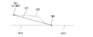
- a specific example of the target travel trajectory will be described with reference to FIG.
- the controller 20 operates at a branch point where a second link LK2 representing a lane shape of a second lane TL2 on a second road R2 branches from first links LK11 and LK12 representing a lane shape of a first lane TL1 on a first road R1.
- the controller 20 calculates the shortcut trajectory ST1 to have a linear portion, for example, and calculates each of the connection points between the shortcut trajectory ST1 and the first link LK11 or LK12, and the connection points between the shortcut trajectory ST1 and the second link LK2. is smoothed to alleviate changes in the curvature of the shortcut trajectory ST1 at these connection points.
- the shortcut trajectory ST1 includes a linear portion, a first transition curve portion formed between the linear portion and the first links LK11 and LK12, and a linear portion between the linear portion and the second link LK2.
- the trajectory may include a second transition curve portion formed. The same applies to the shortcut trajectory ST2, which will be described later. As shown in FIG.
- the shortcut trajectory ST1 is calculated such that at least a portion thereof passes through the range on the first link LK11 side of the left side range and right side range of the second link LK2.
- the target travel trajectory based on the shortcut trajectory ST1 is more effective than the curvature change when the target travel trajectory is generated based on the shape of the second link LK2. Sudden steering can be suppressed by reducing changes in trajectory curvature. As a result, the discomfort given to the occupant can be suppressed.
- the shortcut trajectory ST1 is an example of a "first trajectory" described in the claims.
- the controller 20 includes a map information acquisition section 30 , a self-location information acquisition section 31 , a surrounding situation recognition section 32 , a navigation information acquisition section 33 , and an autonomous driving control section 34 .
- the map information acquisition unit 30 acquires high-precision map information using the map database 13 or a communication device (not shown).
- the self-position information acquisition unit 31 acquires current position information regarding the current position of the own vehicle 1 from the positioning device 12 .
- the surrounding situation recognition unit 32 recognizes the situation around the host vehicle 1 based on the driving information.
- the surrounding situation recognition unit 32 recognizes other vehicles around the host vehicle 1 and lane boundary lines in front of the host vehicle 1 from the sensor information of the sensor 11 .
- the navigation information acquisition unit 33 acquires route information regarding a target travel route to a destination from the navigation system 15.
- the autonomous driving control unit 34 uses the high-precision map information acquired by the map information acquisition unit 30 , the current position information acquired by the self-location information acquisition unit 31 , the recognition result of the surrounding situation recognition unit 32 , and the navigation information acquisition unit 33 Based on the acquired route information, the autonomous speed control (constant speed control, inter-vehicle distance control) and autonomous steering control (lane keeping control, lane change control, overtaking support control, route driving support control) are executed.
- the autonomous running control unit 34 controls the vehicle behavior control device 19 to maintain a set running speed.
- the autonomous running control unit 34 controls the vehicle behavior control device 19 to maintain the set inter-vehicle distance with the set traveling speed as the upper limit.
- the autonomous driving control unit 34 controls the vehicle behavior control device 19 so that the host vehicle 1 runs near the center of the lane. Furthermore, in the lane change support control, the autonomous driving control unit 34 turns on the direction indicator when the occupant operates the direction indicator lever, and determines whether a predetermined lane change start condition is satisfied. When the lane change start conditions are met, the vehicle behavior control device 19 is controlled so that the own vehicle 1 moves laterally to the adjacent lane to which the lane change is to be made.
- the autonomous driving control unit 34 presents an overtaking proposal to the occupant when a predetermined overtaking proposal condition is satisfied.
- the vehicle behavior control device 19 is controlled so that the host vehicle 1 changes lanes.
- the autonomous driving control unit 34 performs control at a point a predetermined distance before a driving direction change point such as a branch point, a confluence point, an exit, or a toll booth on the target driving route set by the navigation system 15. In order to travel along the target travel route, the lane in which the own vehicle 1 should currently travel (target lane) is selected.
- a route proposal is proposed to the occupant.
- the vehicle behavior control device controls the vehicle 1 to change lanes to the target lane when the occupant operates the lane change support switch 186 of the input device 18 to approve the route travel proposal and satisfies predetermined route travel execution conditions. Controls 19.
- the autonomous travel control unit 34 In these autonomous steering controls, the autonomous travel control unit 34 generates a target travel trajectory and controls the vehicle behavior control device 19 to travel along the target travel trajectory. For this reason, the autonomous running control section 34 includes a trajectory generation section 34a and a vehicle control section 34b.
- the trajectory generation section 34a generates a target travel trajectory based on the high-precision map information, current position information, and the recognition result of the surrounding situation recognition section 32.
- the vehicle control unit 34b controls the vehicle behavior control device 19 so that the host vehicle 1 travels along the target travel trajectory generated by the trajectory generation unit 34b.
- the steering actuator may be controlled so that the host vehicle 1 travels along the target travel trajectory, or a driving force difference or a braking force difference may be applied between the left wheel and the right wheel.
- the trajectory generation unit 34a when it is difficult to recognize lane boundaries based on sensor information from the sensor 11, the trajectory generation unit 34a generates a target travel trajectory based on the link shape of the high-precision map information acquired by the map information acquisition unit 30. It's fine. Further, when the host vehicle 1 moves from the first road R1 to the second road R2, the target travel trajectory may be generated based on the link shape of the high-precision map information acquired by the map information acquisition unit 30. For example, the trajectory generation unit 34a can detect the lane boundary line based on the sensor information, and when the host vehicle 1 continues to travel on the first road R1, the trajectory generation unit 34a can detect the lane boundary line recognition result based on the sensor information of the sensor 11. A target travel trajectory may be generated based on the following.
- the trajectory generation unit 34a determines the travel path of the vehicle 1 based on the recognition result of the left and right lane boundary lines of the second lane TL2 of the second road R2.
- the target travel trajectory may be generated based on the recognition result of the lane boundary line based on the sensor information of the sensor 11.
- the trajectory generation unit 34a determines whether a lane change is to be performed from the first lane TL1 of the first road R1 to the second lane TL2 of the second road R2 through lane change support control or route travel support control. You may do so.
- the trajectory generation unit 34a When a lane change is made from the first lane TL1 to the second lane TL2, for example, the trajectory generation unit 34a generates a first predetermined distance L1 from the branching start point Ps where the second lane TL2 starts branching from the first lane TL1.
- the trajectory generation unit 34a may start generating a target travel trajectory based on the link shape of the high-precision map information.
- the vehicle control unit 34b controls the target travel generated based on the recognition result of the lane boundary line by the sensor 11 until the own vehicle 1 reaches a point a second predetermined distance L2 ( ⁇ L1) before the branching start point Ps.
- the vehicle behavior control device 19 may be controlled so that the vehicle travels along the track. After passing a point a second predetermined distance L2 before the branch start point Ps, the vehicle behavior control device 19 is controlled to drive along the target travel trajectory generated based on the link shape of the high-precision map information. It's fine.
- the target travel trajectory used for autonomous steering control is generated based on the recognition result of the lane boundary line by the sensor 11.
- the target travel trajectory may be switched to a target travel trajectory generated based on the link shape of the high-precision map information.
- the trajectory generation unit 34a calculates the shortcut trajectory ST1 described with reference to FIG. 4. That is, a node ND1 where a second link LK2 representing the lane shape of the second lane TL2 on the second road R2 branches from first links LK11 and LK12 representing the lane shape of the first lane TL1 on the first road R1; A shortcut trajectory ST1 is calculated that connects a link constituent point CP1 on the second link LK2 that is a predetermined distance away from the node ND1 along the second link LK2.
- the trajectory generation unit 34a determines whether the shortcut trajectory ST1 should be corrected. For example, as shown in FIG. 6, if the first link LK12 and the second link LK2 curve in the same direction (that is, if the first lane TL1 and the second lane TL2 curve in the same direction), the shortcut trajectory ST1 may be on a trajectory that straddles the first link LK12.
- the host vehicle 1 travels along the target travel trajectory generated based on such a shortcut trajectory ST1
- the host vehicle 1 temporarily moves laterally in the opposite direction to the branching direction of the second lane TL2, causing the occupants to feel uncomfortable. There is a risk of giving.
- the trajectory generation unit 34a determines whether the shortcut trajectory ST1 is a trajectory that straddles the first link LK12. If the shortcut trajectory ST1 is not a trajectory that straddles the first link LK12, the trajectory generation unit 34a does not modify the shortcut trajectory ST1.
- the trajectory generation unit 34a When the shortcut trajectory ST1 is a trajectory that straddles the first link LK12, the trajectory generation unit 34a generates a link component point CP1 that is the intersection of the tangents of the first links LK11 and LK12 and the second link LK2 at the node ND1 and the node.
- a trajectory connecting to ND1 is calculated as a corrected shortcut trajectory ST2. If the intersection of the tangents of the first links LK11 and LK12 and the second link LK2 at the node ND1 is another node ND2, a modified shortcut trajectory ST2 connecting the nodes ND1 and ND2 may be calculated. .
- the trajectory generation unit 34a determines whether or not to generate a target travel trajectory based on the shortcut trajectory ST1 or the corrected shortcut trajectory ST2. For example, when the curvature change of the second link LK2 (that is, the curvature change of the second lane TL2) is small, when the host vehicle 1 travels along the target travel trajectory based on the shortcut trajectory ST1 or the corrected shortcut trajectory ST2, the first lane There is a possibility that the movement from R1 to the second road R2 will be slow, giving the occupants a sense of discomfort.
- the trajectory generation unit 34a calculates the curvature difference between the curvature of the first link LK1 and the curvature of the second link LK2 (that is, the curvature difference between the curvature of the first lane TL and the curvature of the second lane TL2). calculate. If the curvature difference is greater than or equal to a predetermined threshold, a target traveling trajectory is generated based on the shortcut trajectory ST1 or the corrected shortcut trajectory ST2. In this case, if the shortcut trajectory ST1 is a trajectory that straddles the first link LK12, a target travel trajectory is generated based on the corrected shortcut trajectory ST2, and the shortcut trajectory ST1 is a trajectory that does not straddle the first link LK12. In this case, a target traveling trajectory is generated based on the shortcut trajectory ST1. When the curvature difference is less than 1, the trajectory generation unit 34a generates a target traveling trajectory based on the shape of the second link LK2.
- the shortcut trajectory ST1 and the corrected shortcut trajectory ST2 may become a trajectory in which the own vehicle 1 protrudes outside the second lane TL. That is, when the host vehicle 1 travels along the target travel trajectory based on the shortcut trajectory ST1 or the corrected shortcut trajectory ST2, the host vehicle 1 travels along the lane boundary of the second lane TL on the opposite side to the first lane TL1. There is a possibility that it will exceed 1.
- the shortcut trajectory ST1 in FIG. 7 the shortcut trajectory ST1 passes through a position farther from the first link LK12 than the second link LK2 in the section S. Therefore, when traveling along the shortcut trajectory ST1, there is a possibility that the host vehicle 1 crosses the lane boundary of the second lane TL on the opposite side to the first lane TL1 in the section S.
- the trajectory generation unit 34a determines that when the host vehicle 1 travels along the target travel trajectory based on the shortcut trajectory ST1, the second lane TL is It is determined whether the host vehicle 1 crosses the lane boundary on the opposite side to the first lane TL1.
- the shortcut trajectory ST1 is a trajectory that straddles the first link LK12
- the first lane TL1 among the lane boundaries of the second lane TL It is determined whether or not the own vehicle 1 crosses the lane boundary on the opposite side.
- the trajectory generation unit 34a When the own vehicle 1 travels along the target traveling trajectory based on the shortcut trajectory ST1 or the corrected shortcut trajectory ST2, when the own vehicle 1 crosses the lane boundary of the second lane TL on the opposite side to the first lane TL1. If determined, the trajectory generation unit 34a generates a target travel trajectory based on the shape of the second link LK2.
- the shortcut trajectory ST1 is a trajectory that does not straddle the first link LK12, and even if the host vehicle 1 travels along the target travel trajectory based on the shortcut trajectory ST1, the first lane TL1 and the lane boundary of the second lane TL may overlap. If the host vehicle 1 does not cross the lane boundary on the opposite side, the trajectory generation unit 34a generates a target travel trajectory based on the shortcut trajectory ST1.
- the trajectory generation unit 34a generates a target travel trajectory based on the corrected shortcut trajectory ST2.
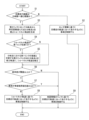
- FIG. 8 is a flowchart of an example of the vehicle travel control method according to the embodiment.
- the trajectory generation unit 34a determines whether the target travel route of the own vehicle 1 is a route leading to a branch road. If the target travel route is a route that leads to a branch road (step S1: Y), the process advances to step S3. If the target travel route is not a route that leads to a branch road (step S1: N), the process advances to step S2.
- the trajectory generation unit 34a generates a target travel trajectory based on the recognition result of lane boundaries based on sensor information from the sensor 11.
- the vehicle control unit 34b controls the vehicle behavior control device 19 so that the host vehicle 1 travels along the target travel trajectory generated by the trajectory generation unit 34b. The process then ends.
- step S3 the trajectory generating unit 34a connects a node ND1 where the second link LK2 branches from the first links LK11 and LK12, and a point on the second link LK2 that is a predetermined distance away from the node ND1 along the second link LK2.
- a shortcut trajectory ST1 connecting between is calculated.
- step S4 the trajectory generation unit 34a determines whether the shortcut trajectory ST1 straddles the first link LK12. If the shortcut trajectory ST1 straddles the first link LK12 (step S4: Y), the process proceeds to step S5. If the shortcut trajectory ST1 does not cross the first link LK12 (step S4: N), the process proceeds to step S6.
- step S5 the trajectory generation unit 34a calculates a trajectory connecting the node ND1 and the intersection of the tangents of the first links LK11 and LK12 and the second link LK2 at the node ND1 as a corrected shortcut trajectory ST2. Thereafter, the process proceeds to step S6.
- step S6 the trajectory generation unit 34a determines whether the curvature difference between the curvature of the first lane TL and the curvature of the second lane TL2 is greater than or equal to a threshold value. If the curvature difference is greater than or equal to the threshold (step S6: Y), the process proceeds to step S7. If the curvature difference is not equal to or greater than the threshold (step S6: N), the process proceeds to step S9.
- step S7 the trajectory generation unit 34a determines that when the own vehicle 1 travels along the target traveling trajectory based on the shortcut trajectory ST1 (or the corrected shortcut trajectory ST2 when the corrected shortcut trajectory ST2 is calculated), the second lane TL It is determined whether the host vehicle 1 crosses the lane boundary on the opposite side to the first lane TL1 among the lane boundaries. If the host vehicle 1 crosses the lane boundary (step S7: Y), the process proceeds to step S9. If the host vehicle 1 does not cross the lane boundary (step S7: N), the process proceeds to step S8.
- step S8 the trajectory generation unit 34a generates a target traveling trajectory based on the shortcut trajectory ST1 (or the corrected shortcut trajectory ST2 if the corrected shortcut trajectory ST2 has been calculated).
- the vehicle control unit 34b controls the vehicle behavior control device 19 so that the host vehicle 1 travels along the target travel trajectory generated by the trajectory generation unit 34b.
- step S9 the trajectory generation unit 34a generates a target traveling trajectory based on the link shape of the second link LK2.
- the vehicle control unit 34b controls the vehicle behavior control device 19 so that the host vehicle 1 travels along the target travel trajectory generated by the trajectory generation unit 34b. The process then ends.
- the controller 20 causes the vehicle 1 to travel along the lane by automatic steering based on map information representing the lane shape using nodes and links.
- the controller 20 performs a process of determining whether or not the target travel route of the vehicle 1 traveling on the first road is a route leading to a second road branching from the first road in front of the vehicle 1;
- the driving route is a route that proceeds to a second road
- the first link which is a link that represents the lane shape of the first lane on the first road
- the second link which is a link that represents the lane shape of the second lane, on the second road.
- a first trajectory is calculated that connects the branch point where the two links diverge and a point on the second link that is a predetermined distance away from the branch point along the second link, and a target travel trajectory is determined based on the first trajectory.
- a setting process and a process of controlling the host vehicle 1 to travel along the target travel trajectory are executed.
- the controller 20 determines whether the first trajectory straddles the first link, and if the first trajectory does not straddle the first link, sets a target travel trajectory based on the first trajectory, When the first trajectory straddles the first link, the target travel trajectory may be set based on the second trajectory that connects the intersection of the tangent of the first link and the second link at the branch point and the branch point.
- the controller 20 controls the host vehicle 1 to travel along the target travel trajectory when the curvature difference between the curvature of the first lane and the curvature of the second lane is greater than or equal to a predetermined threshold.
- the host vehicle 1 may be controlled to travel along the travel trajectory generated based on the second link.
- the controller 20 estimates whether or not the own vehicle 1 will cross the lane boundary on the opposite side to the first lane among the lane boundaries of the second lane, and If it is estimated that the vehicle 1 exceeds the lane boundary, the host vehicle 1 may be controlled to travel along the travel trajectory generated based on the second link. Thereby, when the host vehicle 1 travels along the target travel trajectory based on the first trajectory or the second trajectory, it is possible to suppress the host vehicle 1 from protruding out of the second lane to the opposite side of the first lane.
Landscapes
- Engineering & Computer Science (AREA)
- Automation & Control Theory (AREA)
- Transportation (AREA)
- Mechanical Engineering (AREA)
- Human Computer Interaction (AREA)
- Control Of Driving Devices And Active Controlling Of Vehicle (AREA)
- Steering Control In Accordance With Driving Conditions (AREA)
- Navigation (AREA)
- Traffic Control Systems (AREA)
Priority Applications (7)
| Application Number | Priority Date | Filing Date | Title |
|---|---|---|---|
| JP2024507466A JP7816491B2 (ja) | 2022-03-18 | 2022-03-18 | 車両走行制御方法及び車両走行制御装置 |
| EP22932234.2A EP4494959A4 (en) | 2022-03-18 | 2022-03-18 | VEHICLE DRIVING CONTROL METHOD AND VEHICLE DRIVING CONTROL DEVICE |
| CN202280093441.3A CN118843571B (zh) | 2022-03-18 | 2022-03-18 | 车辆行驶控制方法及车辆行驶控制装置 |
| MX2024011082A MX2024011082A (es) | 2022-03-18 | 2022-03-18 | Metodo de control de desplazamiento de vehiculo y dispositivo de control de desplazamiento de vehiculo. |
| MYPI2024005126A MY208918A (en) | 2022-03-18 | 2022-03-18 | Vehicle travel control method and vehicle travel control device |
| PCT/JP2022/012837 WO2023175966A1 (ja) | 2022-03-18 | 2022-03-18 | 車両走行制御方法及び車両走行制御装置 |
| US18/845,201 US12466400B2 (en) | 2022-03-18 | 2022-03-18 | Vehicle travel control method and vehicle travel control device |
Applications Claiming Priority (1)
| Application Number | Priority Date | Filing Date | Title |
|---|---|---|---|
| PCT/JP2022/012837 WO2023175966A1 (ja) | 2022-03-18 | 2022-03-18 | 車両走行制御方法及び車両走行制御装置 |
Publications (1)
| Publication Number | Publication Date |
|---|---|
| WO2023175966A1 true WO2023175966A1 (ja) | 2023-09-21 |
Family
ID=88023062
Family Applications (1)
| Application Number | Title | Priority Date | Filing Date |
|---|---|---|---|
| PCT/JP2022/012837 Ceased WO2023175966A1 (ja) | 2022-03-18 | 2022-03-18 | 車両走行制御方法及び車両走行制御装置 |
Country Status (7)
| Country | Link |
|---|---|
| US (1) | US12466400B2 (https=) |
| EP (1) | EP4494959A4 (https=) |
| JP (1) | JP7816491B2 (https=) |
| CN (1) | CN118843571B (https=) |
| MX (1) | MX2024011082A (https=) |
| MY (1) | MY208918A (https=) |
| WO (1) | WO2023175966A1 (https=) |
Cited By (1)
| Publication number | Priority date | Publication date | Assignee | Title |
|---|---|---|---|---|
| WO2026022924A1 (ja) * | 2024-07-23 | 2026-01-29 | 日産自動車株式会社 | 車線境界線検出方法及び車線境界線検出装置 |
Citations (4)
| Publication number | Priority date | Publication date | Assignee | Title |
|---|---|---|---|---|
| JP2007164339A (ja) * | 2005-12-12 | 2007-06-28 | Toyota Central Res & Dev Lab Inc | 計算処理プログラム、計算処理装置、及び計算処理方法 |
| JP2010221859A (ja) * | 2009-03-24 | 2010-10-07 | Hitachi Automotive Systems Ltd | 車両運転支援装置 |
| JP2012002753A (ja) * | 2010-06-18 | 2012-01-05 | Navitime Japan Co Ltd | ナビゲーションシステム、ナビゲーション装置、ナビゲーションサーバ、ナビゲーション方法、および、プログラム |
| JP2019215177A (ja) * | 2018-06-11 | 2019-12-19 | 株式会社デンソー | 軌道設定装置 |
Family Cites Families (14)
| Publication number | Priority date | Publication date | Assignee | Title |
|---|---|---|---|---|
| JPH0944243A (ja) * | 1995-08-01 | 1997-02-14 | Komatsu Ltd | 移動体の走行コース作成装置 |
| JP5656067B2 (ja) * | 2010-12-03 | 2015-01-21 | アイシン・エィ・ダブリュ株式会社 | 道路ノード位置管理システム、道路ノード位置管理方法、及び道路ノード位置管理プログラム |
| JP2018181034A (ja) * | 2017-04-17 | 2018-11-15 | 株式会社ゼンリン | 走行支援装置、走行支援方法およびそのためのデータ構造 |
| CN111094897A (zh) * | 2017-09-08 | 2020-05-01 | 日产自动车株式会社 | 驾驶辅助方法以及驾驶辅助装置 |
| US11181920B2 (en) * | 2018-08-28 | 2021-11-23 | Denso Corporation | Travel assistance method and travel assistance apparatus |
| US11097748B2 (en) | 2018-10-23 | 2021-08-24 | Baidu Usa Llc | Two-step reference line smoothing method to mimic human driving behaviors for autonomous driving cars |
| JP2020082772A (ja) * | 2018-11-16 | 2020-06-04 | アイシン・エィ・ダブリュ株式会社 | 目標軌道取得システムおよび目標軌道取得プログラム |
| JP6818788B2 (ja) * | 2019-02-05 | 2021-01-20 | 本田技研工業株式会社 | 車両並びにその制御装置及び制御方法 |
| JP7180426B2 (ja) * | 2019-02-06 | 2022-11-30 | トヨタ自動車株式会社 | 車両制御システム |
| JP7331450B2 (ja) * | 2019-05-15 | 2023-08-23 | 日産自動車株式会社 | 車両の走行制御方法及び走行制御装置 |
| JP2021043047A (ja) * | 2019-09-10 | 2021-03-18 | トヨタ自動車株式会社 | 走行予定経路通知装置 |
| JP7400508B2 (ja) * | 2020-02-03 | 2023-12-19 | 株式会社デンソー | 軌道生成装置、軌道生成方法、軌道生成プログラム |
| JP7484317B2 (ja) * | 2020-03-27 | 2024-05-16 | 株式会社アイシン | 運転支援装置及びコンピュータプログラム |
| FR3122390B1 (fr) * | 2021-05-03 | 2023-11-03 | Renault Sas | Procédé de commande d’un véhicule autonome. |
-
2022
- 2022-03-18 MY MYPI2024005126A patent/MY208918A/en unknown
- 2022-03-18 EP EP22932234.2A patent/EP4494959A4/en active Pending
- 2022-03-18 MX MX2024011082A patent/MX2024011082A/es unknown
- 2022-03-18 JP JP2024507466A patent/JP7816491B2/ja active Active
- 2022-03-18 CN CN202280093441.3A patent/CN118843571B/zh active Active
- 2022-03-18 WO PCT/JP2022/012837 patent/WO2023175966A1/ja not_active Ceased
- 2022-03-18 US US18/845,201 patent/US12466400B2/en active Active
Patent Citations (4)
| Publication number | Priority date | Publication date | Assignee | Title |
|---|---|---|---|---|
| JP2007164339A (ja) * | 2005-12-12 | 2007-06-28 | Toyota Central Res & Dev Lab Inc | 計算処理プログラム、計算処理装置、及び計算処理方法 |
| JP2010221859A (ja) * | 2009-03-24 | 2010-10-07 | Hitachi Automotive Systems Ltd | 車両運転支援装置 |
| JP2012002753A (ja) * | 2010-06-18 | 2012-01-05 | Navitime Japan Co Ltd | ナビゲーションシステム、ナビゲーション装置、ナビゲーションサーバ、ナビゲーション方法、および、プログラム |
| JP2019215177A (ja) * | 2018-06-11 | 2019-12-19 | 株式会社デンソー | 軌道設定装置 |
Cited By (1)
| Publication number | Priority date | Publication date | Assignee | Title |
|---|---|---|---|---|
| WO2026022924A1 (ja) * | 2024-07-23 | 2026-01-29 | 日産自動車株式会社 | 車線境界線検出方法及び車線境界線検出装置 |
Also Published As
| Publication number | Publication date |
|---|---|
| US12466400B2 (en) | 2025-11-11 |
| JPWO2023175966A1 (https=) | 2023-09-21 |
| CN118843571B (zh) | 2025-11-11 |
| US20250100552A1 (en) | 2025-03-27 |
| CN118843571A (zh) | 2024-10-25 |
| MY208918A (en) | 2025-06-11 |
| EP4494959A4 (en) | 2025-04-16 |
| EP4494959A1 (en) | 2025-01-22 |
| MX2024011082A (es) | 2024-09-23 |
| JP7816491B2 (ja) | 2026-02-18 |
Similar Documents
| Publication | Publication Date | Title |
|---|---|---|
| JP6469635B2 (ja) | 車両制御装置 | |
| CN114761300A (zh) | 驾驶控制方法及驾驶控制装置 | |
| CN107107750B (zh) | 目标路径生成装置及行驶控制装置 | |
| CN110171421B (zh) | 车辆控制装置 | |
| CN109649391A (zh) | 车辆控制装置 | |
| JP6673531B2 (ja) | 運転支援車両の目標車速生成方法及び目標車速生成装置 | |
| WO2016110729A1 (ja) | 目標車速生成装置および走行制御装置 | |
| CN111348042A (zh) | 车辆控制装置 | |
| WO2019077669A1 (ja) | 車両制御装置 | |
| JP7768347B2 (ja) | 運転支援方法及び運転支援装置 | |
| US12012104B2 (en) | Driving control method and driving control device | |
| WO2022249470A1 (ja) | 運転支援方法及び運転支援装置 | |
| WO2022254509A1 (ja) | 画像制御方法及び画像制御装置 | |
| CN114867650A (zh) | 车辆的行驶控制方法及行驶控制装置 | |
| WO2023175966A1 (ja) | 車両走行制御方法及び車両走行制御装置 | |
| WO2022195775A1 (ja) | 車両の走行制御方法及び走行制御装置 | |
| JP7841585B2 (ja) | 運転支援方法及び運転支援装置 | |
| JP7427699B2 (ja) | 運転支援装置、車両、運転支援方法、記憶媒体及びプログラム | |
| JP7622900B2 (ja) | 運転支援方法及び運転支援装置 | |
| JP7605332B2 (ja) | 運転制御方法及び運転制御装置 | |
| JP7740345B2 (ja) | 運転制御方法及び運転制御装置 | |
| WO2023089701A1 (ja) | 車両制御方法及び車両制御装置 | |
| JP2022182463A (ja) | 運転支援方法及び運転支援装置 | |
| JPWO2023047453A5 (https=) | ||
| JP7740492B2 (ja) | 運転支援方法及び運転支援装置 |
Legal Events
| Date | Code | Title | Description |
|---|---|---|---|
| 121 | Ep: the epo has been informed by wipo that ep was designated in this application |
Ref document number: 22932234 Country of ref document: EP Kind code of ref document: A1 |
|
| ENP | Entry into the national phase |
Ref document number: 2024507466 Country of ref document: JP Kind code of ref document: A |
|
| WWE | Wipo information: entry into national phase |
Ref document number: 18845201 Country of ref document: US |
|
| REG | Reference to national code |
Ref country code: BR Ref legal event code: B01A Ref document number: 112024017734 Country of ref document: BR |
|
| WWE | Wipo information: entry into national phase |
Ref document number: MX/A/2024/011082 Country of ref document: MX Ref document number: 202280093441.3 Country of ref document: CN |
|
| WWE | Wipo information: entry into national phase |
Ref document number: 202447073696 Country of ref document: IN |
|
| WWE | Wipo information: entry into national phase |
Ref document number: 2022932234 Country of ref document: EP |
|
| NENP | Non-entry into the national phase |
Ref country code: DE |
|
| ENP | Entry into the national phase |
Ref document number: 2022932234 Country of ref document: EP Effective date: 20241018 |
|
| ENP | Entry into the national phase |
Ref document number: 112024017734 Country of ref document: BR Kind code of ref document: A2 Effective date: 20240828 |
|
| WWP | Wipo information: published in national office |
Ref document number: 18845201 Country of ref document: US |
|
| WWG | Wipo information: grant in national office |
Ref document number: 18845201 Country of ref document: US |