WO2023127906A1 - チャック及びチャック付き電子レンジ用包装袋 - Google Patents
チャック及びチャック付き電子レンジ用包装袋 Download PDFInfo
- Publication number
- WO2023127906A1 WO2023127906A1 PCT/JP2022/048320 JP2022048320W WO2023127906A1 WO 2023127906 A1 WO2023127906 A1 WO 2023127906A1 JP 2022048320 W JP2022048320 W JP 2022048320W WO 2023127906 A1 WO2023127906 A1 WO 2023127906A1
- Authority
- WO
- WIPO (PCT)
- Prior art keywords
- bag
- zipper
- packaging
- tape
- bag body
- Prior art date
- Legal status (The legal status is an assumption and is not a legal conclusion. Google has not performed a legal analysis and makes no representation as to the accuracy of the status listed.)
- Ceased
Links
Images





Classifications
-
- B—PERFORMING OPERATIONS; TRANSPORTING
- B65—CONVEYING; PACKING; STORING; HANDLING THIN OR FILAMENTARY MATERIAL
- B65D—CONTAINERS FOR STORAGE OR TRANSPORT OF ARTICLES OR MATERIALS, e.g. BAGS, BARRELS, BOTTLES, BOXES, CANS, CARTONS, CRATES, DRUMS, JARS, TANKS, HOPPERS, FORWARDING CONTAINERS; ACCESSORIES, CLOSURES, OR FITTINGS THEREFOR; PACKAGING ELEMENTS; PACKAGES
- B65D81/00—Containers, packaging elements, or packages, for contents presenting particular transport or storage problems, or adapted to be used for non-packaging purposes after removal of contents
- B65D81/34—Containers, packaging elements, or packages, for contents presenting particular transport or storage problems, or adapted to be used for non-packaging purposes after removal of contents for packaging foodstuffs or other articles intended to be cooked or heated within the package
- B65D81/3446—Containers, packaging elements, or packages, for contents presenting particular transport or storage problems, or adapted to be used for non-packaging purposes after removal of contents for packaging foodstuffs or other articles intended to be cooked or heated within the package specially adapted to be heated by microwaves
- B65D81/3461—Flexible containers, e.g. bags, pouches, envelopes
-
- B—PERFORMING OPERATIONS; TRANSPORTING
- B65—CONVEYING; PACKING; STORING; HANDLING THIN OR FILAMENTARY MATERIAL
- B65D—CONTAINERS FOR STORAGE OR TRANSPORT OF ARTICLES OR MATERIALS, e.g. BAGS, BARRELS, BOTTLES, BOXES, CANS, CARTONS, CRATES, DRUMS, JARS, TANKS, HOPPERS, FORWARDING CONTAINERS; ACCESSORIES, CLOSURES, OR FITTINGS THEREFOR; PACKAGING ELEMENTS; PACKAGES
- B65D33/00—Details of, or accessories for, sacks or bags
- B65D33/01—Ventilation or drainage of bags
-
- B—PERFORMING OPERATIONS; TRANSPORTING
- B65—CONVEYING; PACKING; STORING; HANDLING THIN OR FILAMENTARY MATERIAL
- B65D—CONTAINERS FOR STORAGE OR TRANSPORT OF ARTICLES OR MATERIALS, e.g. BAGS, BARRELS, BOTTLES, BOXES, CANS, CARTONS, CRATES, DRUMS, JARS, TANKS, HOPPERS, FORWARDING CONTAINERS; ACCESSORIES, CLOSURES, OR FITTINGS THEREFOR; PACKAGING ELEMENTS; PACKAGES
- B65D33/00—Details of, or accessories for, sacks or bags
- B65D33/16—End- or aperture-closing arrangements or devices
- B65D33/25—Riveting; Dovetailing; Screwing; using press buttons or slide fasteners
- B65D33/2508—Riveting; Dovetailing; Screwing; using press buttons or slide fasteners using slide fasteners with interlocking members having a substantially uniform section throughout the length of the fastener; Sliders therefor
-
- B—PERFORMING OPERATIONS; TRANSPORTING
- B65—CONVEYING; PACKING; STORING; HANDLING THIN OR FILAMENTARY MATERIAL
- B65D—CONTAINERS FOR STORAGE OR TRANSPORT OF ARTICLES OR MATERIALS, e.g. BAGS, BARRELS, BOTTLES, BOXES, CANS, CARTONS, CRATES, DRUMS, JARS, TANKS, HOPPERS, FORWARDING CONTAINERS; ACCESSORIES, CLOSURES, OR FITTINGS THEREFOR; PACKAGING ELEMENTS; PACKAGES
- B65D33/00—Details of, or accessories for, sacks or bags
- B65D33/16—End- or aperture-closing arrangements or devices
- B65D33/25—Riveting; Dovetailing; Screwing; using press buttons or slide fasteners
- B65D33/2508—Riveting; Dovetailing; Screwing; using press buttons or slide fasteners using slide fasteners with interlocking members having a substantially uniform section throughout the length of the fastener; Sliders therefor
- B65D33/2575—Riveting; Dovetailing; Screwing; using press buttons or slide fasteners using slide fasteners with interlocking members having a substantially uniform section throughout the length of the fastener; Sliders therefor the slide fastener providing access to the bag through a bag wall, e.g. intended to be cut open by the consumer
- B65D33/2583—Riveting; Dovetailing; Screwing; using press buttons or slide fasteners using slide fasteners with interlocking members having a substantially uniform section throughout the length of the fastener; Sliders therefor the slide fastener providing access to the bag through a bag wall, e.g. intended to be cut open by the consumer the slide fastener being attached to one wall only
-
- B—PERFORMING OPERATIONS; TRANSPORTING
- B65—CONVEYING; PACKING; STORING; HANDLING THIN OR FILAMENTARY MATERIAL
- B65D—CONTAINERS FOR STORAGE OR TRANSPORT OF ARTICLES OR MATERIALS, e.g. BAGS, BARRELS, BOTTLES, BOXES, CANS, CARTONS, CRATES, DRUMS, JARS, TANKS, HOPPERS, FORWARDING CONTAINERS; ACCESSORIES, CLOSURES, OR FITTINGS THEREFOR; PACKAGING ELEMENTS; PACKAGES
- B65D2205/00—Venting means
Definitions
- the present invention relates to a zipper and a microwave packaging bag with a zipper.
- This application claims priority based on Japanese Patent Application No. 2021-214417 filed in Japan on December 28, 2021, the content of which is incorporated herein.
- a microwave packaging bag with a zipper is provided with a mechanism for releasing steam generated inside the bag to the outside of the bag during microwave heating by a microwave oven.
- Patent Document 1 a bag provided with a male and female claw type zipper made of synthetic resin is provided with a base piece formed on the base of the zipper on the inner surface of the opening of the bag and having an appropriate length in the longitudinal direction.
- a synthetic resin bag with a zipper is disclosed in which bonded portions are surface-bonded with a required width at intervals and weakly bonded portions having easy peelability are provided between the bonded portions.
- the present invention has been proposed to solve the above-described problems, and is to stably release the steam generated inside the bag to the outside of the bag during microwave heating by a microwave oven.
- a first aspect of the present invention is a zipper attached to a bag body in which steam is generated, comprising: a first zipper tape having a base and a first fitting portion; and a second zipper tape having a second fitting portion that can be fitted and sealed, wherein the base portions of the first zipper tape are positioned on both sides of the first fitting portion. is provided with a vapor passage portion for passing the vapor generated inside the bag.
- the vaporizing portion includes either or both of cuts and holes formed in the base portion of the first zipper tape.
- a third aspect of the present invention is a packaging bag for a microwave oven with a zipper, comprising: a bag body in which the inner surfaces of packaging films are overlapped and the peripheral edge portions are stuck together; and the zipper of the first or second aspect.
- the first zipper tape and the second zipper tape are welded to the inner surface of the packaging film, and the vaporizing section is adapted to pass steam generated inside the bag body to the inside of the bag body after opening the bag body. It escapes to the outside of the bag through the opening.
- a fourth aspect of the present invention is the microwave packaging bag with a zipper according to the third aspect, wherein the first zipper tape is welded to the inner surface of the packaging film, and the second zipper tape is the In a state where the first zipper tape is covered, the first zipper tape is welded to the inner surface of the packaging film to which the first zipper tape is welded, and the welded portion of the first zipper tape and the welded portion of the second zipper tape.
- the opening is formed by tearing the packaging film between the sides near the periphery of the bag.
- a fifth aspect of the present invention is the packaging bag for a microwave oven with a chuck according to the fourth aspect, which includes a cut tape attached to the inner surface of the packaging film, and a knob provided on one end side of the cut tape. The opening is formed by pulling the part and tearing the packaging film along the cut tape.
- a sixth aspect of the present invention is the packaging bag for a microwave oven with a zipper according to any one of the third to fifth aspects, wherein liquid content is accommodated inside the bag body.
- a microwave oven with a chuck that allows steam generated inside the bag body to escape to the outside of the bag body in a stable state during microwave heating by the microwave oven. It is possible to provide a packaging bag for
- FIG. 2 is a cross-sectional view of the microwave packaging bag with zipper taken along the line II-II shown in FIG. 1;
- FIG. 3 is a cross-sectional view showing a state in which steam generated inside the bag body of the packaging bag for microwave oven with zipper shown in FIG. 2 is released to the outside of the bag body.
- FIG. 3 is a plan view showing the configuration of a microwave packaging bag according to a second embodiment of the present invention;
- FIG. 5 is a cross-sectional view of the zipper-equipped packaging bag for a microwave oven taken along the line VV shown in FIG. 4; Fig.
- FIG. 6 is an enlarged cross-sectional view of the enclosing portion T shown in Fig. 5, showing a state before opening the packaging bag for a microwave oven with a chuck.
- FIG. 5 is a cross-sectional view along the line VII-VII shown in FIG. 4, where (A) is a view showing the state before the pinching piece of the cut tape is pulled, and (B) is a diagram showing the pinching piece of the cut tape after being pulled. It is a figure which shows a state.
- Fig. 6 is an enlarged cross-sectional view of the enclosing portion T shown in Fig. 5, showing a state after opening the packaging bag for a microwave oven with a chuck.
- FIG. 5 is a cross-sectional view along the line VII-VII shown in FIG. 4, where (A) is a view showing the state before the pinching piece of the cut tape is pulled, and (B) is a diagram showing the pinching piece of the cut tape after being pulled. It is a figure which shows
- FIG. 6 is an enlarged cross-sectional view of the enclosing portion T shown in FIG. 5 , showing a state in which the sealing by the chuck is released after the packaging bag for microwave oven with zipper is opened.
- Fig. 6 is an enlarged cross-sectional view of the enclosing portion T shown in Fig. 5, showing a state in which steam generated inside the package body of the microwave oven packaging bag with zipper is released to the outside of the bag body.
- FIG. 10 is a plan view showing the configuration of a packaging bag for microwave ovens with a chuck according to a third embodiment of the present invention
- FIG. 12 is a cross-sectional view of the microwave packaging bag with zipper taken along the line XII-XII shown in FIG. 11;
- FIG. 13 is a cross-sectional view showing a state before the contents are accommodated inside the bag body of the packaging bag for microwave oven with zipper shown in FIG. 12 ;
- FIG. 10 is a plan view showing another configuration example of the vaporization section;
- FIG. 4 is a plan view showing the configuration of a microwave packaging bag according to Modification 1 of the first embodiment of the present invention;
- FIG. 10 is a plan view showing the configuration of a microwave packaging bag according to Modification 2 of the first embodiment of the present invention;
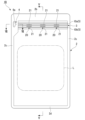
- FIGS. 1 to 3 First, as a first embodiment of the present invention, a packaging bag for microwave oven with zipper (hereinafter simply referred to as "packaging bag") 1A shown in FIGS. 1 to 3, for example, will be described.
- FIG. 1 is a plan view showing the configuration of the packaging bag 1A.
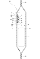
- FIG. 2 is a cross-sectional view of the packaging bag 1A taken along line II-II shown in FIG.
- FIG. 3 is a cross-sectional view showing a state in which steam generated inside the bag body 2 of the packaging bag 1A is released to the outside of the bag body 2. As shown in FIG.
- the packaging bag 1A of this embodiment includes a bag body 2, a zipper 3, and a cut-open portion 4.
- the cut-open portion 4 can tear a part of the bag body 2. can open the bag 2 to form an opening (not shown in FIGS. 1-3).
- the packaging bag 1A is subjected to microwave heating in a microwave oven in a state in which the food is contained inside the bag body 2 through the opening and then the zipper of the zipper 3 is sealed, thereby cooking the food. conduct.
- the left-right direction in FIG. 1 may be referred to as the width direction of the bag body 2 .
- the vertical direction in FIGS. 1 and 2 may be referred to as the vertical direction of the bag body 2, and the side of the bag body 2 on which the cut-open portion 4 is provided in the vertical direction may be referred to as the upper side.
- the bag body 2 is in a state in which a liquid content L such as a seasoning liquid is stored in advance.
- a liquid content L such as a seasoning liquid
- the content L is not necessarily limited to liquid, and may be powder or solid.
- the content L may be, for example, freeze-dried ingredients other than the seasonings described above.
- the packaging bag 1A of the present embodiment is not limited to the above-described bag body 2 in which the contents L are stored in advance, and the bag body 2 may be empty before being opened.
- the bag body 2 is formed by stacking three packaging films 6a, 6b, and 6c and adhering the top, side, and bottom peripheral edges to form an upper edge seal portion 2b, a side edge seal portion 2c, and a bottom edge seal portion 2c.
- An edge seal portion 2d is formed, and an accommodation space K for accommodating contents L such as foodstuffs is provided therein.
- the bag body 2 has a packaging film 6a that constitutes one surface, a packaging film 6b that constitutes the other surface, and a packaging film 6c that constitutes the bottom surface.
- the packaging film 6c folded in half is sandwiched between the films 6a and 6b, and the films are laminated together, and the peripheral edges thereof are bonded together by heat welding (hereinafter, also referred to as "heat fusion") to form a standing pouch.
- heat fusion heat welding
- It is a self-supporting bottom gusset bag with a gusset at the bottom.
- the bag body 2 is a bottom gusset bag composed of two wrapping films in the upper portion and four wrapping films in the lower portion with the boundary R as a boundary.
- the packaging films 6a, 6b, and 6c are laminated films made of resin obtained by laminating a base layer forming the outer surface of the bag 2 and a sealant layer forming the inner surface of the bag 2 through an adhesive layer. consists of
- a dry lamination method can be suitably used in which an adhesive diluted with an organic solvent is applied, dried, and then thermocompression bonded.
- the base material layer is a layer having excellent properties such as impact resistance and pinhole resistance.
- a biaxially stretched film on which a metal or metal oxide is vapor-deposited can be preferably used.
- the sealant layer as a layer having heat sealability, for example, low density, medium density, high density, linear low density polyethylene (hereinafter referred to as "PE”), homo, random, block polypropylene, etc. (hereinafter referred to as "PP”) and the like can be preferably used.
- PE linear low density polyethylene
- PP homo, random, block polypropylene, etc.
- a polyester-based adhesive or a polyether-based adhesive can be suitably used as an adhesive for dry lamination.
- packaging films 6a, 6b, and 6c may be composed of laminated films containing at least one or more intermediate layers and printed layers in addition to the base layer and sealant layer described above.
- packaging films 6a, 6b, 6c include laminated films obtained by sequentially laminating a substrate layer, a printed layer, an adhesive layer, an intermediate layer, an adhesive layer, and a sealant layer; Laminated films in which an agent layer and a sealant layer are sequentially laminated can be used.
- the same material as the base layer can be suitably used as a layer having excellent properties such as impact resistance and pinhole resistance.
- the printed layer is formed by printing on the back surface of the base material layer.
- the packaging films 6a, 6b, and 6c are formed by a dry lamination method using a substrate layer made of a biaxially oriented polyethylene terephthalate film (hereinafter referred to as “PET”) having a thickness of 12 ⁇ m, and an adhesive layer. , an intermediate layer made of transparent vapor-deposited PET with a thickness of 12 ⁇ m, an adhesive layer, an intermediate layer made of a biaxially oriented nylon film with a thickness of 15 ⁇ m (hereinafter referred to as “ONY”), an adhesive layer, and a thickness of 60 to 100 ⁇ m.
- a laminated film obtained by sequentially laminating a sealant layer made of unstretched polypropylene (hereinafter referred to as "CPP") is used.
- the zipper 3 is a zipper tape provided with a zipper, which is attached to the inner surface of one of the packaging films 6a constituting the surface of the bag 2, and a first zipper tape 7 attached to the back of the bag 2. and a second zipper tape 8 attached by being stuck to the inner surface of the other packaging film 6b.
- the zipper 3, the first zipper tape 7 and the second zipper tape 8 are shaped to extend in one direction.
- the direction in which the zipper 3 and the first zipper tape 7 and the second zipper tape 8 extend is sometimes referred to as the longitudinal direction. This longitudinal direction is the same as the left-right direction (that is, the width direction of the bag body 2) in FIG.
- the first zipper tape 7 and the second zipper tape 8 have film-like flat bases 7c, 8c thermally welded to the inner surfaces of the packaging films 6a, 6b, and fitting protruding from the central portions of the bases 7c, 8c. It has parts 7a and 8a, respectively.
- the first zipper tape 7 has a first fitting portion 7a.
- the first fitting portion 7a constitutes either one of a male fitting portion and a female fitting portion that are fitted to each other.
- the first fitting portion 7 a is provided so as to protrude from the central portion of the surface of the first zipper tape 7 facing the second zipper tape 8 .
- the first fitting portion 7a constitutes a male fitting portion.
- the first zipper tape 7 has a first gap D1 between itself and the inner surface of the packaging film 6a, and is positioned on both sides of the first gap D1 (both sides in the vertical direction of the bag body 2). It is attached to the upper portion of the inner surface of the packaging film 6a by heat-sealing it across the width direction of the bag body 2 via a pair of first welded portions 7b.
- the vertical direction of the bag body 2 is the same as the direction orthogonal to the longitudinal direction and along the packaging film 6a (or the base portion 7c).
- the second zipper tape 8 has a second fitting portion 8a.
- the second fitting portion 8a constitutes the other of a male fitting portion and a female fitting portion that are fitted to each other.
- the second fitting portion 8 a is provided so as to protrude from the central portion of the surface of the second zipper tape 8 facing the first zipper tape 7 .
- the second fitting portion 8a constitutes a female fitting portion.
- the second zipper tape 8 is heat-sealed and attached to the upper portion of the inner surface of the packaging film 6b across the width of the bag body 2 via a pair of second welded portions 8b.
- any material that can be heat-sealed to the sealant layer of the packaging film 6a can be used.
- PE-based resin, PP-based resin, or the like can be used.
- the first zipper tape 7 and the second zipper tape 7 are connected to the second fitting portion 8a, which is the female fitting portion, by fitting the first fitting portion 7a, which is the male fitting portion, into the second fitting portion 8a, which is the female fitting portion. It is possible to seal across the width of the bag body 2 from the zipper tape 8 of the bag body 2 .
- the cut-open portion 4 has a notch 4a that forms an opening by tearing a part of the bag body 2.
- the notch 4 a is provided in the side edge seal portion 2 c between the upper edge seal portion 2 b of the bag body 2 and the chuck 3 .
- the notch 4a is a pentagonal tortoise shell (base) notch of the home base shape, but it can be appropriately selected from an I-shaped I-shaped notch, a V-shaped V-shaped notch, a U-shaped U-shaped notch, and the like.
- the bag body 2 can be manually cut and opened from a notch 4a serving as an opening start portion without using scissors or the like.
- the vaporizing portions 20 are positioned on both sides of the first fitting portion 7a of the first zipper tape 7, and are arranged in parallel with each other, and the first zipper tape 7 extends from a portion of the base portion 7c. It is composed of a pair of cuts 21 formed so as to split linearly in the direction. The pair of cuts 21 linearly penetrates the base portion 7c of the first zipper tape 7 in the thickness direction between the first fitting portion 7a and the pair of first welding portions 7b.
- a plurality (three in the present embodiment) of the vaporizing sections 20 are provided side by side in the direction in which the first zipper tape 7 extends.
- the first zipper tape 7 is provided with three vapor passage portions 20 (a pair of cuts 21) at the central portion in the longitudinal direction and at both sides of the central portion.
- the pressure of the steam S generated inside the bag body 2 passes through the vaporization section 20, which is released by the pressure of the vapor S. 1, the gap D1 and the housing space K are communicated with each other.
- the cut surfaces forming the cuts 21 are brought into close contact with each other, and the pressure of the steam S generated inside the bag body 2 swells the bag body 2 to bring it into a fitted state. Since the base 7c is pulled away from the bag body 2 (that is, the packaging film 6a) by the chuck fitting portions (fitting portions 7a and 8a that are fitted to each other), the cut surfaces are opened. At this time, while the first zipper tape 7 is deformed, the first gap D1 between the pair of cuts 21 is wide open like a tunnel.
- the steam S generated inside the bag body 2 can be stably released to the outside of the bag body 2 from the opening through the vaporizing portion 20 that is opened. .
- the width of the base portions 7c and 8c of the first zipper tape 7 and the second zipper tape 8 (the width in the vertical direction) is about 10 to 30 mm.
- the width of the first welded portion 7b and the second welded portion 8b (the width in the vertical direction) is about 3 mm to 5 mm.
- the length of the slit 21 (the length in the longitudinal direction) may be appropriately selected for the purpose of making it easier or harder for the steam S to escape, depending on the content L and the purpose of cooking.
- the distance from the point is preferably 3 to 30 mm, more preferably 5 to 10 mm.
- the position of the steaming portion 20 in the width direction of the bag body 2 may be appropriately selected for the purpose of making it easier or harder for the steam S to escape from the content L and the purpose of cooking. It is preferable to provide in the central portion in the width direction, more specifically, in the range of 1/3 of the central portion when the length in the width direction of the bag body 2 is divided into three equal parts. Within this range, when the steam S is generated, the bag body 2 swells and rises, and the steam passage part 20 is largely opened, so that the steam S can be easily removed.
- the vaporizing portion 20 is provided on the side of the first zipper tape 7, but the vaporizing portion 20 may be provided on the side of the second zipper tape 8.
- a configuration in which the vapor passage portion 20 is provided on both the first zipper tape 7 and the second zipper tape 8 may be employed.
- the first fitting portion 7a has a per unit length of Since the amount of resin is small and the rigidity is low, when the bag body 2 is inflated by the pressure of the steam S, the steam passage part 20 is easily deformed and the steam S is easily released. Therefore, it is preferable to provide the vaporizing portion 20 on the side of the first zipper tape 7 having the first fitting portion 7a, which is the male fitting portion.
- an empty bag body 2 whose upper part is not attached is prepared. That is, of the three packaging films 6a, 6b, and 6c, only the side and bottom portions are bonded together by heat sealing, and the empty bag body 2 having the upper opening before bonding the upper peripheral edge portion by heat sealing. prepare.
- the bag 2 is sealed. Specifically, in a state in which the engagement between the first fitting portion 7a and the second fitting portion 8a of the chuck 3 is released, the content L is filled into the accommodation space K of the bag body 2 from the upper opening. After that, the upper peripheral edge portions of the packaging films 6a and 6b are adhered together by thermal welding to form the upper edge seal portion 2b. As a result, the storage space K is hermetically sealed, and the packaging bag 1A containing the contents L is shipped.
- the packaging bag 1A can stand on its own, and even if the zipper 3 is sealed, the steam S escapes through the vaporization part 20, so the bag body 2 will not burst. Moreover, since the chuck 3 is sealed, the heated contents L do not scatter and contaminate the inside of the microwave oven. After cooking, the chuck 3 is opened and the cooked contents L can be taken out from the opening.
- packaging bag for microwave oven with zipper hereinafter simply referred to as "packaging bag” 1B shown in FIGS. 4 to 10, for example, will be described.
- FIG. 4 is a plan view showing the configuration of the packaging bag 1B.
- FIG. 5 is a cross-sectional view of the packaging bag 1B along the line segment VV shown in FIG.
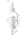
- FIG. 6 is an enlarged cross-sectional view of the enclosing portion T shown in FIG. 5, showing a state before the packaging bag 1B is opened.
- 7A and 7B are cross-sectional views taken along line VII-VII shown in FIG. ) is a diagram showing a state in which the pinch piece 9a of the cut tape 9 is pulled.
- FIG. 8 is an enlarged cross-sectional view of the enclosing portion T shown in FIG. 5, showing the state after the packaging bag 1B is opened.
- FIG. 5 is a cross-sectional view of the packaging bag 1B along the line segment VV shown in FIG.
- FIG. 6 is an enlarged cross-sectional view of the enclosing portion T shown in FIG. 5, showing a state before the packaging bag 1B is opened.
- 7A and 7B
- FIG. 9 is an enlarged cross-sectional view of the enclosing portion T shown in FIG. 5, showing a state in which the sealing by the chuck 3 is released after the packaging bag 1B is opened.
- FIG. 10 is an enlarged cross-sectional view of the enclosing portion T shown in FIG. 5, showing a state in which the steam S generated inside the bag body 2 of the packaging bag 1B is released to the outside of the bag body 2.
- the packaging bag 1B of this embodiment includes a bag body 2, a zipper 3, a cut-open portion 4, and an easy peel portion 5.
- the cut-open portion 4 opens the bag body 2.
- the bag 2 can be unsealed to form an opening 2a (see FIGS. 8-10) by tearing a portion of the opening.
- the packaging bag 1B is subjected to microwave heating by a microwave oven in a state in which the food material is accommodated inside the bag body 2 through the opening 2a, and then, with the zipper of the zipper 3 sealed, so that the food material is cooked. I do.
- the bag body 2 that constitutes the packaging bag 1B of the present embodiment is formed by superimposing two packaging films 6a and 6b and bonding the top, side and bottom peripheral edges of each other to form an upper edge seal portion 2b. , a side edge seal portion 2c and a bottom edge seal portion 2d, and a flat bag having no gusset at the bottom (hereinafter also referred to as a "square bag").
- the bag body 2 has an accommodation space K for accommodating contents L such as foodstuffs. It is in a state of
- the zipper 3 constituting the packaging bag 1B of the present embodiment is a zipper tape provided with a zipper.
- the first zipper tapes 7 have a first gap D1 between them and the inner surface of the packaging film 6a, and are positioned on both sides of the first gap D1 (both sides in the vertical direction of the bag body 2). It is heat-sealed and attached to the upper portion of the inner surface of the packaging film 6a across the width of the bag body 2 via the first welded portion 7b.
- the second zipper tape 8 covers the first zipper tape 7 and has a second gap D2 between itself and the inner surface of the packaging film 6a. In this embodiment, it is heat-sealed and attached to the upper portion of the inner surface of the packaging film 6a across the width direction of the bag body 2 via the second welding portion 8b positioned on the upper side.
- the cut-open portion 4 is located between the first welded portion 7b of the first zipper tape 7 and the second welded portion 8b of the second zipper tape 8, at the periphery of the bag body 2 (that is, the upper edge seal).
- the opening 2a can be formed by tearing the packaging film 6a between the sides close to the part 2b).
- the cut open portion 4 has a cut tape 9 provided with a gripping piece 9a on one end side.
- the cut tape 9 extends in the width direction of the bag 2 above the first fitting portion 7a of the first zipper tape 7 on the inner surface of the packaging film 6a (in other words, on the side close to the periphery of the bag 2). installed across.
- the cut tape 9 is attached to the inner surface of the packaging film 6a via a third welded portion 9b located between the second welded portion 8b and the first welded portion 7b adjacent to the second welded portion 8b. It is heat-sealed across the width of the bag body 2 .
- the cut tape 9 is detachably adhered to the second zipper tape 8 via the easily peelable layer 10a at the bonding portion of the side peripheral edge of the bag body 2 .
- the form of peeling of the easy peeling layer 10a there are interfacial peeling, cohesive peeling, and interlaminar peeling, and these may be appropriately used according to sealing conditions, sterilization conditions, and the like.
- a laminate of a support layer made of PE and an adhesive layer containing ethylene vinyl acetate copolymer (EVA) and an adhesive can be used.
- EVA ethylene vinyl acetate copolymer
- cohesive peeling a laminate of a support layer made of PE or PP and a cohesive peeling layer containing PP, PE and, if necessary, other materials can be used.
- the sealant layer, the adhesive layer, the intermediate layer, the adhesive layer, and the easy peeling layer 10a described above are sequentially laminated, or the sealant layer, the adhesive layer, the intermediate layer, the adhesive layer, and the intermediate layer. and an adhesive layer and an easy peeling layer 10a sequentially laminated, a sealant layer, an adhesive layer, an intermediate layer, a print layer, an adhesive layer, and an easy peeling layer 10a sequentially laminated, a sealant layer and an adhesive layer , an intermediate layer, a printed layer, an adhesive layer, an intermediate layer, an adhesive layer, and an easily peelable layer 10a, which are sequentially laminated.
- the grip piece 9a is provided so as to be separable from the bag body 2 by cutting the packaging films 6a, 6b and the second zipper tape 8 along its contour.
- a slit 9c is provided by cutting the second zipper tape 8 and the packaging film 6b in a direction perpendicular to the cut tape 9. As shown in FIG.
- the packaging film 6a is linearly torn along the cut tape 9 while pulling the grip piece 9a.
- the cut tape 9 is peeled from the second zipper tape 8 together with the easily peelable layer 10a starting from the cut 9c. Thereby, it is possible to form a linear opening 2a over the width direction of the bag body 2 .
- the opening 2a of the bag body 2 formed by the cut-open portion 4 can be sealed with the chuck 3.
- the packaging bag 1B of this embodiment as shown in FIG. It is possible to store the foodstuff E inside the bag body 2 through the opening 2a.
- the easy-peel part 5 is an easily peelable part that adheres between the inner surface of the packaging film 6a and the second chuck tape 8 together with the easily peelable layer 10a described above. It has a layer 10b. That is, a pair of easily peelable layers 10a and 10b located on both sides of the first zipper tape 7 (both sides in the vertical direction of the bag body 2) is provided between the packaging film 6a and the second zipper tape 8. are releasably adhered to each other. As for the easy peeling layer 10b, the same one as the easy peeling layer 10a described above can be used.
- the easy peel portion 5 has an easy peel tape 11 that is detachably adhered to the second zipper tape 8 via an easy peel layer 10b.
- the easy peel tape 11 extends across the width direction of the bag body 2 on the inner surface of the packaging film 6a via a fourth welded portion 11a located on the other side (lower side in this embodiment) across the second gap D2. are heat-sealed.
- the sealant layer, the adhesive layer, the intermediate layer, the adhesive layer, and the easy peeling layer 10b are sequentially laminated, or the sealant layer, the adhesive layer, the intermediate layer, the adhesive layer, and the intermediate layer are laminated.
- a layer, an intermediate layer, a printed layer, an adhesive layer, an intermediate layer, an adhesive layer, and an easily peelable layer 10b may be sequentially laminated.
- the easy peel tape 11 includes a sealant layer made of CPP with a thickness of 60 ⁇ m, an adhesive layer, an intermediate layer made of ONY with a thickness of 25 ⁇ m, an adhesive layer, and an intermediate layer made of ONY with a thickness of 25 ⁇ m. , an adhesive layer and a polyethylene (PE)-based easy peeling layer 10a having a thickness of 50 ⁇ m are sequentially laminated.
- a sealant layer made of CPP with a thickness of 60 ⁇ m an adhesive layer, an intermediate layer made of ONY with a thickness of 25 ⁇ m, an adhesive layer, and an intermediate layer made of ONY with a thickness of 25 ⁇ m.
- PE polyethylene
- the opening 2a is formed in the bag body 2 by the cut-open section 4, and after the bag body 2 is unsealed, the first fitting section 7a and the second fitting section 7a by the chuck 3 are opened.
- the second zipper tape 8 is separated from the easily peelable layer 10b by releasing the engagement with the fitting portion 8a.
- the opening 2a is formed, and the easily peelable layer 10b prevents the liquid contents L from entering the second gap D2 before the bag 2 is opened. .
- the packaging bag 1B of the present embodiment has base portions 7c at positions on both sides (both sides in the vertical direction of the bag body 2) sandwiching the first fitting portion 7a of the first zipper tape 7, and inside the bag body 2.
- a vapor passage portion 20 is provided for releasing the generated steam S to the outside of the bag body 2 from the opening portion 2a.
- the vaporizing portions 20 are positioned on both sides of the first fitting portion 7a of the first zipper tape 7, and are arranged in parallel with each other, and the first zipper tape 7 extends from a portion of the base portion 7c. It is composed of a pair of cuts 21 formed so as to split linearly in the direction. The pair of cuts 21 linearly penetrates the base portion 7c of the first zipper tape 7 in the thickness direction between the first fitting portion 7a and the pair of first welding portions 7b.
- a plurality (three in the present embodiment) of the vaporizing sections 20 are provided side by side in the direction in which the first zipper tape 7 extends.
- the first zipper tape 7 is provided with three vapor passage portions 20 (a pair of cuts 21) at the central portion in the longitudinal direction and at both sides of the central portion.
- the pressure of the steam S generated inside the bag 2 passes through the vaporization section 20, which is released.
- the first gap D1 and the second gap D2 are communicated with each other.
- the cut surfaces forming the cuts 21 are brought into close contact with each other, and the pressure of the steam S generated inside the bag body 2 swells the bag body 2 to bring it into a fitted state. Since the base portion 7c is pulled in a direction away from the bag body 2 (that is, the packaging film 6a) by the chuck fitting portion, the space between the cut surfaces is opened. At this time, while the first zipper tape 7 is deformed, the first gap D1 between the pair of cuts 21 is wide open like a tunnel.
- the steam S generated inside the bag body 2 can be stably released from the opening 2a to the outside of the bag body 2 through the opened vaporizing portion 20. be.
- an empty bag body 2 whose upper part is not attached is prepared. Specifically, of the two packaging films 6a and 6b, only the side portions and the bottom portions are bonded together by heat sealing, and the upper peripheral edge portions are bonded together by heat sealing. Prepare 2.
- the bag 2 is sealed. Specifically, after filling the storage space K of the bag body 2 with the contents L from the upper opening, the upper peripheral edge portions of the packaging films 6a and 6b are adhered together by heat welding to form the upper edge seal portion 2b. . As a result, the storage space K is hermetically sealed, and the packaging bag 1B containing the contents L is shipped.
- the consumer tears the packaging film 6a linearly along the cut tape 9 while pulling the tab 9a of the cut tape 9 to form the opening 2a, and then opens the zipper 3. Then, ingredients, water, seasoning liquid, etc. are introduced into the bag body 2 through the opening 2a. After that, the chuck 3 is sealed, and the food is cooked in a microwave oven.
- the chuck 3 is sealed, the steam S escapes through the steaming part 20, so the bag body 2 will not burst. Moreover, since the chuck 3 is sealed, the heated contents L do not scatter and contaminate the inside of the microwave oven. After cooking, the chuck 3 is opened and the cooked contents L can be taken out from the opening 2a.
- the packaging bag 1B of the present embodiment does not require an operation to release the engagement of the zipper 3 when the content L is filled, and is similar to a packaging bag without the zipper 3. It is possible to fill the content L using the filling device of . Further, after the content L is filled, the fitting portion of the chuck 3 is released by a finger in order for the consumer to put in the foods, etc. from the opening 2a of the packaging bag 1B, and the chuck 3 is kept open until the foods, etc. are put in. The contents L do not come into contact with the fitting part of the. Therefore, the consumer's fingers are not soiled when releasing the engagement portion of the chuck 3 .
- the zipper 3 is attached to one of the packaging films 6a, and the zipper 3 is separated from the liquid surface of the contents L, so that heating is possible. It is possible to prevent the content L from spilling out of the steaming part 20 during cooking. Therefore, even if the microwave oven is small and does not have enough height for the bag body 2 to stand on its own, the consumer can safely cook by heating without staining the interior of the microwave oven.
- packaging bag for microwave oven with zipper hereinafter simply referred to as "packaging bag” 1C shown in FIGS. 11 to 13, for example, will be described.
- FIG. 11 is a plan view showing the configuration of the packaging bag 1C.
- FIG. 12 is a cross-sectional view of the packaging bag 1C taken along line XII-XII shown in FIG.
- FIG. 13 is a cross-sectional view showing a state before contents are accommodated inside the bag body of the packaging bag 1C.
- the packaging bag 1C of this embodiment includes a bag body 2, a zipper 3, a cut-open portion 4, and an easy peel portion 5.
- the cut-open portion 4 The bag 2 can be opened by tearing a portion of the bag 2 to form the opening 2a.
- the packaging bag 1C is subjected to microwave heating by a microwave oven in a state in which the food is contained inside the bag body 2 through the opening 2a, and then, with the zipper of the zipper 3 sealed, so that the food is cooked. I do.
- the bag body 2 constituting the packaging bag 1C of the present embodiment includes a packaging film 6a constituting the front surface, which is one surface, and a packaging film 6a constituting the back surface, which is the other surface. It has a film 6b and a packaging film 6c that constitutes the bottom surface thereof, and the packaging film 6c folded in half is sandwiched between the packaging films 6a and 6b and overlapped, and the peripheral edges are bonded together by heat welding. Also called a standing pouch, it is a self-supporting bottom gusset bag with a gusset at the bottom.
- the bag body 2 is a bottom gusset bag composed of two wrapping films in the upper portion and four wrapping films in the lower portion with the boundary R as a boundary.
- the zipper 3 constituting the packaging bag 1C of the present embodiment is a zipper tape provided with a zipper, similar to the packaging bag 1B of the second embodiment.
- the packaging bag 1C of the present embodiment has both sides (both sides in the vertical direction of the bag body 2) sandwiching the first fitting portion 7a of the first zipper tape 7.
- the base portion 7c at the position of is provided with a steam passage portion 20 for releasing the steam S generated inside the bag 2 to the outside of the bag 2 through the opening 2a.
- the vaporized steam released by the pressure of the steam S generated inside the bag body 2 during microwave heating by the microwave oven Through the portion 20, the first gap D1 and the second gap D2 are communicated with each other.
- the cut surfaces forming the cuts 21 are brought into close contact with each other, and the pressure of the steam S generated inside the bag body 2 swells the bag body 2 to bring it into a fitted state. Since the base portion 7c is pulled in a direction away from the bag body 2 (that is, the packaging film 6a) by the chuck fitting portion, the space between the cut surfaces is opened. At this time, while the first zipper tape 7 is deformed, the first gap D1 between the pair of cuts 21 is wide open like a tunnel.
- the steam S generated inside the bag body 2 can be stably released to the outside of the bag body 2 from the opening 2a through the opened vaporizing portion 20. be.
- the method of using the packaging bag 1C of the present embodiment is the same as that of the packaging bag 1B of the second embodiment, so description thereof will be omitted.
- the packaging bag 1C of the present embodiment has the same configuration as the packaging bag 1A of the first embodiment and the packaging bag 1B of the second embodiment. It is possible to obtain the same effects as those of the packaging bag 1B of the embodiment.
- the present invention is not necessarily limited to the first to third embodiments, and various modifications can be made within the scope of the present invention.
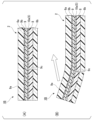
- the vaporization section 20 is not necessarily limited to the one configured by the pair of cuts 21, and may be configured as shown in FIGS. 14A to 14C, for example. be.
- a perforation-like cut 22 is provided, and the perforation-like cut 22 is cut into a line by the pressure of the steam S generated inside the bag body 2. It has a configuration that
- holes 23 and 24 can be formed by punching out the first zipper tape 7 by punching.
- the vapor passage portion 20 is located on both sides of the first fitting portion 7a, and is formed by cutting the first zipper tape 7, and either the slit or the hole is formed. Or it may be a configuration including both. Also, the arrangement and number of the vaporizing units 20 can be changed as appropriate.
- the cut-open portion 4 is not necessarily limited to a configuration in which the opening 2a is formed by tearing the packaging film 6a along the cut tape 9 while pulling the gripping piece 9a provided at one end of the cut tape 9. Instead, the opening may be formed by tearing a part of the bag body 2 .
- the content L may be a cooked food that can be eaten simply by heating it in a microwave oven.
- the filling of the content L is not limited to the above-described upper opening, but may be filled from an opening provided on the side or bottom.
- the vapor passage portion 20 is not limited to a portion that completely penetrates the base portion 7c of the first zipper tape 7, and is a half-penetration portion that does not penetrate a part of the thickness direction of the base portion 7c.
- a configuration in which the semi-penetration portion penetrates when pressure is applied to the chuck 3 may be adopted.
- the first fastener tape 7 is attached to the bag body 2 by affixing a portion of the base portion 7c to the inner surface of the bag body 2 by thermal welding.
- the fitting portion (that is, the second fitting portion 8a) provided on the inner surface of the bag body 2 on the side where the sealant layer is not provided may be formed at the same time as the film of the sealant layer is extruded.
- the peripheral portion of the bag 2 is formed by laminating the packaging films 6a, 6b, 6c together. , 6c.
- the bottom edge seal portion 2d of the bottom gusset bags of the first and third embodiments may be a bent portion.
- a three-sided bag having three peripheral portions bonded together may be used instead of a four-sided bag having four peripheral portions bonded together.
- the bag body 2 of each of the first to third embodiments may be formed from one folded packaging film or from a plurality of folded packaging films.
- the second zipper tape 8 is attached in the packaging bag 1B of the second embodiment and the packaging bag 1C of the third embodiment.
- a thin portion is provided in the base portion 8c on the side closer to the accommodation space K, and when the fitting between the first fitting portion 7a and the second fitting portion 8a is released, the thin portion is broken to close the accommodation space. It is good also as a structure which communicates with K.
- FIG. 15 a packaging bag for microwave oven with zipper (hereinafter simply referred to as "packaging bag") 1AA shown in FIG. 15 will be described.
- the direction in which the chuck 3 extends is called the width direction, and the direction along the front and back surfaces of the packaging bag 1AA and perpendicular to the width direction is called the vertical direction.
- the side on which the chuck 3 is provided is called the upper side of the packaging bag 1AA.
- FIG. 15 is a plan view showing the configuration of the packaging bag 1AA.
- an accommodation opening 2e for accommodating the contents L in advance in the accommodation space K of the bag body 2 is provided in one of the two side parts of the bag body 2. and that the width of the upper edge portion 26, which is the part of the bag body 2 located above the accommodation opening 2e, is shorter than the total widthwise length of the bag body 2 (the overall widthwise length at the position of the accommodation opening 2e).
- a housing opening 2e communicating with the housing space K is provided.
- the side on which the accommodation opening 2e is provided is referred to as the left side of the packaging bag 1AA.
- the upper edge portion 26 includes at least the upper edge seal portion 2 b and the chuck 3 .
- the portion of the bag body 2 where the accommodation opening 2 e is provided protrudes leftward from the left end of the upper edge portion 26 .
- the chuck 3 is provided on one side (that is, the upper part) of the plurality of sides of the bag body 2, but the accommodation opening 2e is different from the side on which the chuck 3 is provided (that is, provided on the one side).
- an empty bag body 2 in which one of the two sides (the left side in FIG. 15) is not bonded is prepared. That is, of the three packaging films 6a, 6b, and 6c, the other of the two sides (the right side in FIG. 15), the top and the bottom are bonded together by heat welding, and the one side An empty bag body 2 having an accommodation opening 2e is prepared before the parts are bonded together by heat welding. Next, after filling the empty bag body 2 with the content L, the bag body 2 is sealed.
- the packaging films 6a and 6b in the storage opening 2e are bonded together by heat welding to form the storage opening sealing portion 2f. .
- the accommodation space K is airtightly sealed, and the packaging bag 1AA in which the content L is accommodated is shipped.
- the packaging bag 1AA of this modified example it is not necessary to perform an operation to release the fitting of the chuck portion 3 when filling the content L, and the same filling device as that used for the packaging bag without the chuck portion 3 is used. Filling of the content L can be performed.
- the zipper 3 is kept closed until the consumer releases the fitting portion of the chuck 3 by fingers so as to put the food material into the packaging bag 1AA from the upper opening of the packaging bag 1AA. Since the fitting is maintained, the contents L do not come into contact with the fitting portion of the chuck 3 (especially the upper side of the fitting portion). Therefore, it is possible to prevent the finger of the consumer from getting dirty when the fitting portion of the chuck 3 is released.
- the width of the upper edge portion 26 is shorter than the total length of the bag body 2 in the width direction, and the portion where the accommodation opening 2e of the bag body 2 is provided is located to the left of the left end of the upper edge portion 26. protrudes to For this reason, when the housing opening 2e and its vicinity are heat-pressed to form the housing opening sealing portion 2f, the heat-pressing can be performed while avoiding the upper edge portion 26, and the effect of the thick chuck 3 on the heat-pressing can be reduced. can be excluded.
- the packaging bag manufacturer prepares the empty bag body 2 having the accommodation opening 2e before heat-sealing, and the food product manufacturer prepares the packaging bag 1AA in which the contents L are accommodated.
- the packaging films 6a and 6b at the storage opening 2e are bonded together by heat welding, thereby forming the storage opening sealing portion 2f.
- the stepped seal portion 2g positioned between the accommodation opening 2e and the bottom edge seal portion 2d is a portion where the two packaging films 6a and 6b are overlapped. Since it is located in the vicinity of the bottom edge seal portion 2d where the bottom edge seal portion 2d is located, a step is generated between both seal portions, and it may be relatively difficult to carry out thermal welding.
- the step seal portion 2g is formed by heat welding, so that the food product maker does not need to form the step seal portion 2g. It is possible to prevent the occurrence of seal failure in the seal portion 2g.
- FIG. 16 is a plan view showing the configuration of the packaging bag 1AB.
- the accommodation opening 2e provided in the vertical intermediate portion of one side portion (the left side portion in FIG. 16) of the bag body 2 is different from the intermediate portion of the one side portion.
- the width of the lower edge portion 27, which is the part of the bag body 2 located, is shorter than the overall widthwise length of the packaging bag 1AB (the overall widthwise length at the position of the accommodation opening 2e). It has a similar configuration.
- the packaging films 6a and 6b in the accommodation opening 2e are removed.
- the receiving port sealing portion 2f is formed by bonding by thermal welding that heats and presses. For this reason, the two packaging films 6a and 6b are heat-sealed to form the accommodation port sealing portion 2f.
- the packaging film 6c folded in two is sandwiched between the packaging films 6a and 6b, and the bottom edge sealing portion 2d is formed by heat-pressing to form the bottom edge sealing portion 2d. In, four wrapping films are heat-sealed.
- the thickness of the fused portion may be different and a step may be generated between the two portions.
- the heating portion such as the heat seal bar is used for the thick upper edge portion and the four sheets when the heat pressing is performed. Since the storage port 2e and its vicinity can be appropriately heated and pressed without riding on the overlapping portion (bottom edge seal portion 2d, etc.) of the packaging film, the pressing force for forming the storage port seal portion 2f is insufficient. can be prevented. Therefore, it is possible to properly form the accommodation port seal portion 2f and reliably seal the accommodation port 2e.
- the configurations of Modifications 1 and 2 may be applied to the second and third embodiments.
- the zipper 3 attached to the bag body 2 in which steam is generated is fitted and sealed by a first zipper tape 7 having a base portion 7c and a first fitting portion 7a and the first fitting portion 7a. and a second zipper tape 8 having a possible second fitting portion 8a, and bag bodies are attached to the base portions 7c of the first zipper tape 7 on both sides of the first fitting portion 7a.
- 2 is provided with a steam passage 20 for passing the steam generated inside.
- the vapor passage portion 20 includes either or both of a cut 21 or 22 and a hole 23 or 24 formed in the base portion 7 c of the first chuck tape 7 .
- a microwave oven packaging bag 1A, 1B, or 1C with a zipper includes a bag body 2 in which the inner surfaces of packaging films 6a and 6b are overlapped and the peripheral edge portions are pasted together, and a zipper 3, and a first zipper tape. 7 and the second zipper tape 8 are welded to the inner surfaces of the packaging films 6a and 6b, and the vaporization section 20 allows the vapor generated inside the bag body 2 to flow through the opening 2a after the bag body 2 is unsealed. Escape to the outside of 2.
- the first zipper tape 7 is welded to the inner surface of the packaging film 6a
- the second zipper tape 8 covers the first zipper tape 7.
- the first zipper tape 7 is welded to the inner surface of the packaging film 6a, and the peripheral edge of the bag is between the welded part of the first zipper tape 7 and the welded part of the second zipper tape 8.
- the opening 2a is formed by tearing the wrapping film 6a between the sides close to the part.
- the zippered microwave oven packaging bag 1A, 1B, or 1C has a cut tape 9 attached to the inner surface of the packaging film 6a. is torn along the cut tape 9 to form the opening 2a.
- a liquid content is accommodated inside the bag body 2 in the zippered microwave oven packaging bag 1A, 1B, or 1C.
- Packaging bag for microwave oven with zipper (packaging bag) 2... Bag body 2a... Opening 3... Chuck 4... Cut open part 4a... Notch 5... Easy peel part 6a, 6b, 6c... Packaging film 7 1st zipper tape 7a 1st fitting part 7b 1st welding part 8 2nd zipper tape 8a 2nd fitting part 8b 2nd welding part 9 Cut tape 9a Binder piece 9b...Third welding part 10a, 10b...Easy peeling layer 11...Easy peel tape 11a...Fourth welding part 20...Vaporization part 21, 22...Cuts 23, 24...Hole L...Contents K...Accommodation Space D1... First gap D2... Second gap E... Food material S... Steam
Landscapes
- Engineering & Computer Science (AREA)
- Mechanical Engineering (AREA)
- Life Sciences & Earth Sciences (AREA)
- Food Science & Technology (AREA)
- Bag Frames (AREA)
- Package Specialized In Special Use (AREA)
Priority Applications (4)
| Application Number | Priority Date | Filing Date | Title |
|---|---|---|---|
| US18/724,486 US20250066080A1 (en) | 2021-12-28 | 2022-12-27 | Zipper and zipper-attached microwave oven applicable packaging bag |
| EP22916128.6A EP4458726A4 (en) | 2021-12-28 | 2022-12-27 | ZIPPER AND MICROWAVE-SAFE PACKAGING BAG WITH A ZIPPER |
| AU2022428326A AU2022428326A1 (en) | 2021-12-28 | 2022-12-27 | Zipper and zipper-attached microwave oven applicable packaging bag |
| JP2023571069A JPWO2023127906A1 (https=) | 2021-12-28 | 2022-12-27 |
Applications Claiming Priority (2)
| Application Number | Priority Date | Filing Date | Title |
|---|---|---|---|
| JP2021214417 | 2021-12-28 | ||
| JP2021-214417 | 2021-12-28 |
Publications (1)
| Publication Number | Publication Date |
|---|---|
| WO2023127906A1 true WO2023127906A1 (ja) | 2023-07-06 |
Family
ID=86999106
Family Applications (1)
| Application Number | Title | Priority Date | Filing Date |
|---|---|---|---|
| PCT/JP2022/048320 Ceased WO2023127906A1 (ja) | 2021-12-28 | 2022-12-27 | チャック及びチャック付き電子レンジ用包装袋 |
Country Status (5)
| Country | Link |
|---|---|
| US (1) | US20250066080A1 (https=) |
| EP (1) | EP4458726A4 (https=) |
| JP (1) | JPWO2023127906A1 (https=) |
| AU (1) | AU2022428326A1 (https=) |
| WO (1) | WO2023127906A1 (https=) |
Cited By (1)
| Publication number | Priority date | Publication date | Assignee | Title |
|---|---|---|---|---|
| WO2025205022A1 (ja) * | 2024-03-27 | 2025-10-02 | 出光ユニテック株式会社 | ジッパーテープ付き容器およびジッパーテープ |
Citations (7)
| Publication number | Priority date | Publication date | Assignee | Title |
|---|---|---|---|---|
| JPH0620253U (ja) * | 1992-03-02 | 1994-03-15 | 株式会社生産日本社 | チャック付袋体 |
| JPH11292158A (ja) * | 1998-04-13 | 1999-10-26 | Showa Highpolymer Co Ltd | プラスチック袋体 |
| JP2000072156A (ja) | 1998-08-26 | 2000-03-07 | Seisan Nipponsha Kk | 合成樹脂製チャック付袋体 |
| JP2000219252A (ja) * | 1999-01-29 | 2000-08-08 | Nihon Tokkyo Kanri Co Ltd | ジッパー付米袋 |
| JP2009269640A (ja) * | 2008-05-02 | 2009-11-19 | Hosokawa Yoko Co Ltd | 再封可能袋体およびチャックテープ |
| WO2016163349A1 (ja) * | 2015-04-06 | 2016-10-13 | 出光ユニテック株式会社 | ジッパーテープ付袋体、その製造方法、および、その製造装置 |
| JP2017039496A (ja) * | 2015-08-17 | 2017-02-23 | 株式会社細川洋行 | チャック付き電子レンジ用包装袋 |
Family Cites Families (2)
| Publication number | Priority date | Publication date | Assignee | Title |
|---|---|---|---|---|
| FR2892709B1 (fr) * | 2005-10-28 | 2008-01-11 | S2F Flexico Sarl | Sachet comportant une ouverture dans des profiles, procede de fabrication correspondant |
| KR102166768B1 (ko) * | 2018-10-17 | 2020-10-16 | 한우 | 발효식품 포장용 지퍼 구조 |
-
2022
- 2022-12-27 WO PCT/JP2022/048320 patent/WO2023127906A1/ja not_active Ceased
- 2022-12-27 EP EP22916128.6A patent/EP4458726A4/en active Pending
- 2022-12-27 AU AU2022428326A patent/AU2022428326A1/en active Pending
- 2022-12-27 US US18/724,486 patent/US20250066080A1/en active Pending
- 2022-12-27 JP JP2023571069A patent/JPWO2023127906A1/ja active Pending
Patent Citations (7)
| Publication number | Priority date | Publication date | Assignee | Title |
|---|---|---|---|---|
| JPH0620253U (ja) * | 1992-03-02 | 1994-03-15 | 株式会社生産日本社 | チャック付袋体 |
| JPH11292158A (ja) * | 1998-04-13 | 1999-10-26 | Showa Highpolymer Co Ltd | プラスチック袋体 |
| JP2000072156A (ja) | 1998-08-26 | 2000-03-07 | Seisan Nipponsha Kk | 合成樹脂製チャック付袋体 |
| JP2000219252A (ja) * | 1999-01-29 | 2000-08-08 | Nihon Tokkyo Kanri Co Ltd | ジッパー付米袋 |
| JP2009269640A (ja) * | 2008-05-02 | 2009-11-19 | Hosokawa Yoko Co Ltd | 再封可能袋体およびチャックテープ |
| WO2016163349A1 (ja) * | 2015-04-06 | 2016-10-13 | 出光ユニテック株式会社 | ジッパーテープ付袋体、その製造方法、および、その製造装置 |
| JP2017039496A (ja) * | 2015-08-17 | 2017-02-23 | 株式会社細川洋行 | チャック付き電子レンジ用包装袋 |
Non-Patent Citations (1)
| Title |
|---|
| See also references of EP4458726A4 |
Cited By (1)
| Publication number | Priority date | Publication date | Assignee | Title |
|---|---|---|---|---|
| WO2025205022A1 (ja) * | 2024-03-27 | 2025-10-02 | 出光ユニテック株式会社 | ジッパーテープ付き容器およびジッパーテープ |
Also Published As
| Publication number | Publication date |
|---|---|
| US20250066080A1 (en) | 2025-02-27 |
| EP4458726A1 (en) | 2024-11-06 |
| EP4458726A4 (en) | 2025-12-24 |
| AU2022428326A1 (en) | 2024-07-11 |
| JPWO2023127906A1 (https=) | 2023-07-06 |
Similar Documents
| Publication | Publication Date | Title |
|---|---|---|
| US8777486B2 (en) | Packaging bag with steam venting function and package using the packaging bag | |
| JP3061234U (ja) | 電子レンジで調理するための食品容器 | |
| JP5508900B2 (ja) | 電子レンジ用調理袋 | |
| JP4463931B2 (ja) | 電子レンジ用包装袋 | |
| JP5887745B2 (ja) | 電子レンジ加熱用容器 | |
| JP3901418B2 (ja) | 圧力逃げを備える包装体及びその製造方法 | |
| US20070257030A1 (en) | Microwaveable package | |
| JP2005306426A (ja) | 電子レンジ加熱用包装袋 | |
| JP2005324846A (ja) | 電子レンジ加熱用包装袋 | |
| WO2023127906A1 (ja) | チャック及びチャック付き電子レンジ用包装袋 | |
| JP7532853B2 (ja) | パウチ | |
| JP2010126241A (ja) | 積層フィルム、積層テープ及びこれを用いた電子レンジ加熱用包装袋 | |
| JP4826279B2 (ja) | 電子レンジ用包装袋 | |
| JP7176250B2 (ja) | パウチ | |
| JP7176251B2 (ja) | パウチ | |
| JP2002249177A (ja) | 電子レンジ用包装袋 | |
| JP2020001819A (ja) | 加熱処理包装袋、加熱処理包装袋の製造方法及び電子レンジ用食品 | |
| JP2000335656A (ja) | 食品用袋 | |
| JP7124394B2 (ja) | 易開封包装袋 | |
| JP2023042192A (ja) | 包装袋 | |
| JP7567205B2 (ja) | パウチ | |
| JP3591290B2 (ja) | 電子レンジ用食品包装袋 | |
| JP4346232B2 (ja) | 加熱対応型密封包装袋 | |
| JP5845681B2 (ja) | 電子レンジ加熱用袋 | |
| JP4529679B2 (ja) | 電子レンジ用食品包装袋 |
Legal Events
| Date | Code | Title | Description |
|---|---|---|---|
| 121 | Ep: the epo has been informed by wipo that ep was designated in this application |
Ref document number: 22916128 Country of ref document: EP Kind code of ref document: A1 |
|
| WWE | Wipo information: entry into national phase |
Ref document number: 2023571069 Country of ref document: JP |
|
| WWE | Wipo information: entry into national phase |
Ref document number: 18724486 Country of ref document: US |
|
| WWE | Wipo information: entry into national phase |
Ref document number: 2022428326 Country of ref document: AU Ref document number: 812486 Country of ref document: NZ Ref document number: AU2022428326 Country of ref document: AU |
|
| NENP | Non-entry into the national phase |
Ref country code: DE |
|
| ENP | Entry into the national phase |
Ref document number: 2022916128 Country of ref document: EP Effective date: 20240729 |
|
| WWP | Wipo information: published in national office |
Ref document number: 18724486 Country of ref document: US |