WO2023074681A1 - 排水処理装置及び排水処理方法 - Google Patents
排水処理装置及び排水処理方法 Download PDFInfo
- Publication number
- WO2023074681A1 WO2023074681A1 PCT/JP2022/039721 JP2022039721W WO2023074681A1 WO 2023074681 A1 WO2023074681 A1 WO 2023074681A1 JP 2022039721 W JP2022039721 W JP 2022039721W WO 2023074681 A1 WO2023074681 A1 WO 2023074681A1
- Authority
- WO
- WIPO (PCT)
- Prior art keywords
- nitrification reaction
- reaction zone
- nitrification
- wastewater
- waste water
- Prior art date
- Legal status (The legal status is an assumption and is not a legal conclusion. Google has not performed a legal analysis and makes no representation as to the accuracy of the status listed.)
- Ceased
Links
Images


Classifications
-
- C—CHEMISTRY; METALLURGY
- C02—TREATMENT OF WATER, WASTE WATER, SEWAGE, OR SLUDGE
- C02F—TREATMENT OF WATER, WASTE WATER, SEWAGE, OR SLUDGE
- C02F1/00—Treatment of water, waste water, or sewage
- C02F1/44—Treatment of water, waste water, or sewage by dialysis, osmosis or reverse osmosis
-
- C—CHEMISTRY; METALLURGY
- C02—TREATMENT OF WATER, WASTE WATER, SEWAGE, OR SLUDGE
- C02F—TREATMENT OF WATER, WASTE WATER, SEWAGE, OR SLUDGE
- C02F3/00—Biological treatment of water, waste water, or sewage
- C02F3/34—Biological treatment of water, waste water, or sewage characterised by the microorganisms used
-
- Y—GENERAL TAGGING OF NEW TECHNOLOGICAL DEVELOPMENTS; GENERAL TAGGING OF CROSS-SECTIONAL TECHNOLOGIES SPANNING OVER SEVERAL SECTIONS OF THE IPC; TECHNICAL SUBJECTS COVERED BY FORMER USPC CROSS-REFERENCE ART COLLECTIONS [XRACs] AND DIGESTS
- Y02—TECHNOLOGIES OR APPLICATIONS FOR MITIGATION OR ADAPTATION AGAINST CLIMATE CHANGE
- Y02W—CLIMATE CHANGE MITIGATION TECHNOLOGIES RELATED TO WASTEWATER TREATMENT OR WASTE MANAGEMENT
- Y02W10/00—Technologies for wastewater treatment
- Y02W10/10—Biological treatment of water, waste water, or sewage
Definitions
- the present invention relates to a wastewater treatment device and a wastewater treatment method.
- nitrifying bacteria organic sludge containing microorganisms (hereinafter referred to as "activated sludge”), convert ammonia contained in wastewater into nitrous acid and nitric acid in the presence of oxygen.
- a wastewater treatment apparatus is known in which a denitrifying reaction in which denitrifying bacteria, which are activated sludge in a state, converts to nitrogen, and a denitrifying reaction are performed in a single reaction tank (see, for example, Patent Document 1).
- the reaction tank includes a partition plate that divides the nitrification reaction zone for carrying out the nitrification reaction and the denitrification reaction zone for carrying out the denitrification reaction.
- a membrane separator that separates and removes solids contained in wastewater that has undergone denitrification (hereinafter referred to as "treated water"), and a membrane separator that cleans the surface or supplies air necessary for the nitrification reaction. and an air diffuser for diffusing air bubbles.
- the wastewater When the water level of the wastewater is higher than the upper end of the partition plate, the wastewater overflows the partition plate and moves from the nitrification reaction area to the denitrification reaction area and returns from the denitrification reaction area to the nitrification reaction area. As a result, a circulation flow that circulates around the partition plate is formed. Therefore, nitrous acid and nitric acid produced in the nitrification reaction zone move to the denitrification reaction zone and are converted to nitrogen in the denitrification reaction zone.
- the water level of the waste water is lower than the upper end of the partition plate, the waste water does not overflow the partition plate.
- a circulation flow is not formed, nitrous acid and nitric acid are produced in the nitrification reaction zone, and the nitrous acid and nitric acid that have previously moved from the nitrification reaction zone to the denitrification reaction zone are converted into nitrogen in the denitrification reaction zone.
- the membrane separation device has a plurality of elongated hollow fiber membranes, and when the lower ends of the hollow fiber membranes are placed on the bottom of the reaction tank, the longitudinal direction of each hollow fiber membrane is along the vertical direction.
- the treated water enters the interior of the hollow fiber membrane, rises vertically, and is discharged to the outside of the reactor. As a result, the water level of the waste water inside the reaction tank is lowered.
- a water level sensor is installed in the reaction tank, and when the water level sensor detects that the water level of the waste water inside the reaction tank has reached the preset minimum water level, the water to be treated, which is waste water before being treated, reacts. It is introduced into the denitrification reaction zone of the tank.
- the opening between the bottom of the reaction tank and the partition plate is more difficult than the air diffuser, for example. It is formed on the bottom side of the reactor.
- the wastewater around the opening moves to the bottom of the membrane separator. Therefore, the water to be treated may be supplied to the denitrification reaction zone of the reaction tank, move through the opening to the bottom of the membrane separation device in the nitrification reaction zone, and be discharged to the outside of the reaction tank by the membrane separation device. . In this case, there is a problem that ammonia is not removed from the water to be treated, and the wastewater treatment cannot be performed properly.
- An object of the present invention is to provide a wastewater treatment apparatus and a wastewater treatment method that can properly perform wastewater treatment.
- the wastewater treatment apparatus of the present invention comprises a nitrification reaction for converting ammonia contained in wastewater into nitrous acid or nitric acid in the presence of oxygen, and nitrous acid or nitric acid produced based on the nitrification reaction.
- a denitrification reaction that converts to nitrogen in anoxic conditions, in a wastewater treatment apparatus for performing a nitrification reaction zone for carrying out the nitrification reaction and a denitrification reaction zone for carrying out the denitrification reaction;
- Membrane separation means installed in the nitrification reaction zone for separating and removing solids contained in the wastewater, and a course for changing the course of the wastewater moving from the denitrification reaction zone to the nitrification reaction zone and heading for the membrane separation means. and changing means.
- the wastewater treatment method of the present invention comprises a nitrification reaction for converting ammonia contained in wastewater into nitrous acid or nitric acid in the presence of oxygen, and nitrous acid or nitric acid produced based on the nitrification reaction. to nitrogen in anoxic conditions, wherein said wastewater moves from a denitrification reaction zone where said denitrification reaction is carried out to a nitrification reaction zone where said nitrification reaction is carried out. a step of advancing the waste water that has moved to the nitrification reaction zone to a membrane separation means installed in the nitrification reaction zone to separate and remove solids contained in the waste water; and a course change step for changing.
- wastewater treatment can be performed appropriately.
- FIG. 1 is a schematic diagram of a waste water treatment apparatus according to an embodiment of the present invention
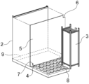
- FIG. FIG. 2 is a perspective view schematically showing the inside of the waste water treatment apparatus of FIG. 1
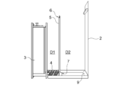
- FIG. 3 is a front view of the waste water treatment apparatus of FIG. 2
- FIG. 4 is an enlarged view of a path changing member in the waste water treatment apparatus of FIG. 3
- FIG. 3 is a rear view of the waste water treatment apparatus of FIG. 2
- FIG. 3 is a left side view of the waste water treatment apparatus of FIG. 2 viewed from the direction of the denitrification reaction zone
- FIG. 3 is a right side view of the waste water treatment apparatus of FIG. 2 viewed from the direction of the nitrification reaction area
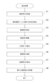
- 2 is a flow chart showing a procedure of waste water treatment performed by the waste water treatment apparatus of FIG. 1;
- FIG. 1 is a schematic diagram of a waste water treatment device 10 according to an embodiment of the present invention.
- the wastewater treatment apparatus 10 of FIG. oxygen supply means
- a partition plate 5 dividing means.
- a water tank 1 to be treated and a pump P1, a pump P1 and a liquid level sensor LS, a blower B and an air diffuser 4, and a pump P2 and a membrane separation device 3 are connected.
- the water tank 1 to be treated stores the water to be treated (raw water) that is supplied to the reaction tank 2 and treated, and the water to be treated is supplied into the reaction tank 2 .
- the water to be treated supplied from the water tank 1 to be treated undergoes a nitrification reaction that converts ammonia contained in the water to nitrous acid and nitric acid in the presence of oxygen, and nitrite and nitric acid to nitrogen in an oxygen-free state.
- a transforming denitrification reaction is applied.
- the nitrification reaction is carried out by activated sludge nitrifying bacteria, and the denitrification reaction is carried out by activated sludge denitrifying bacteria.
- a maximum water level HWL at which the supply of water to be treated from the water tank 1 is stopped and a minimum water level LWL at which the supply of water to be treated from the water tank 1 is started are set in the reaction tank 2.
- a liquid level sensor LS detects the lowest water level LWL of the water to be treated, the pump P1 is driven to start supplying the water to be treated from the water tank 1 to the reaction tank 2, and the liquid level sensor LS detects the water level of the water to be treated.
- the pump P1 is stopped and the supply of the water to be treated from the water tank 1 to be treated to the reaction tank 2 is stopped.
- the membrane separation device 3 has a rectangular parallelepiped housing that extends in the vertical direction when installed in the reaction vessel 2, and a plurality of hollow fiber membranes installed inside the housing.
- the four side surfaces of the housing of the membrane separation device 3 are made up of dividable elongated plate-like members, and the bottom of the housing is open.
- the treated water enters the housing from the bottom of the housing of the membrane separation device 3 and moves from the surface of the hollow fiber membrane to the interior of the hollow fiber membrane. Solids contained in the treated water are separated and removed when passing through the membrane separator 3 .
- An air diffuser (not shown) is installed between the bottom of the reaction vessel 2 and the membrane separation device 3 .
- An air diffuser (not shown) supplies air to the membrane separation device 3, and the air collides with the surface of the hollow fiber membranes of the membrane separation device 3 to wash the membrane separation device 3. inhibits fouling.
- the blower B supplies air to the air diffuser 4.
- the air diffuser 4 diffuses a large amount of fine air having an air diameter of 20 to 500 ⁇ m, for example, from the diffuser plate of the air diffuser 4 to the nitrification reaction area D1 where the nitrification reaction is performed. supply the oxygen it needs.
- the air diffuser 4 is arranged in a region different from the membrane separation device 3 in the nitrification reaction region D1.
- the partition plate 5 divides the reaction tank 2 into a nitrification reaction area D1 and a denitrification reaction area D2 in which the denitrification reaction is performed.
- FIG. 2 is a perspective view schematically showing the inside of the waste water treatment apparatus 10 of FIG. 1
- FIG. 3 is a front view of the waste water treatment apparatus 10 of FIG. 2
- FIG. 4 is a course in the waste water treatment apparatus 10 of FIG. 5 is a rear view of the waste water treatment device 10 of FIG. 2
- FIG. 6 is a left side view of the waste water treatment device 10 of FIG. 2 viewed from the direction of the denitrification reaction zone D2.
- FIG. 7 is a right side view of the waste water treatment apparatus 10 of FIG. 2 viewed from the direction of the nitrification reaction area D1.
- the partition plate 5 has an overflow end 6 where the water to be treated overflows from the nitrification reaction zone D1 to the denitrification reaction zone D2, and an overflow end 6 where the water to be treated flows from the denitrification reaction zone D2 to the nitrification reaction zone D1. It has an opening 7 for moving to.
- the overflow end 6 may have a plurality of overflow points with different distances from the bottom of the reaction tank 2 in order to adjust the amount of overflow of the water to be treated.
- the opening 7 is provided in the partition plate 5 near the bottom of the reaction vessel 2 .
- the opening 7 serves as an air diffuser 4 for diffusing air into the nitrification reaction area D1 in order to prevent the water to be treated in which oxygen is dissolved in the nitrification reaction area D1 from flowing back to the denitrification reaction area D2. It is preferable that the diffuser plate is provided closer to the bottom side of the reaction tank than the diffuser plate and that the opening area is small.
- the area of the opening 7 may be 0.3 to 3.5% of the substantial area of the partition plate 5, that is, the area of the partition plate 5 itself excluding the opening 7.
- the opening 7 is preferably remote from the membrane separation device 3 in order to prevent the water to be treated that has moved from the denitrification reaction region D2 to the nitrification reaction region D1 from entering the membrane separation device 3 immediately.
- the membrane separator 3 and the opening 7 are arranged diagonally at the bottom of the nitrification reaction zone D1 of the reaction tank 2 .
- the water to be treated overflows the overflow end 6 of the partition plate 5 and moves from the nitrification reaction region D1 to the denitrification reaction region D2, Via the opening 7, the denitrification reaction zone D2 returns to the nitrification reaction zone D1. Thereby, a circulation flow that circulates around the partition plate 5 is formed. Therefore, the nitrous acid and nitric acid generated in the nitrification reaction area D1 move to the denitrification reaction area D2 and are converted into nitrogen in the denitrification reaction area D2.
- the overflow end 6 and the opening 7 are arranged diagonally on the partition plate 5 . Since the amount of waste water overflowing is the largest in the upper part of the overflow end 6, by arranging the overflow end 6 and the opening 7 on a diagonal line, circulation having a mixed state necessary for the nitrification reaction and the denitrification reaction is achieved. It is possible to effectively form a stream and perform efficient wastewater treatment.
- the opening 7 is provided closer to the bottom side of the reaction tank 2 than the air diffuser 4, and an upward flow is formed by air bubbles diffused from the air diffuser 4 in the nitrification reaction zone D1. ing. Therefore, when the water level of the waste water is higher than the upper end of the partition plate 5 and the circulation flow is formed around the partition plate 5, most of the water to be treated that flows into the nitrification reaction area D1 from the opening 7 is dispersed. It passes through the gas device 4 and moves to the upper nitrification reaction region D1, and the rest forms a short-circuit flow moving in the region between the bottom of the reaction tank 2 and the gas diffuser 4 in the direction of the membrane separation device 3.
- the short-circuit flow is a local flow having a residence time different from that of the circulating flow formed around the partition plate 5 .
- FIG. 4 is an enlarged view of the path changing member 8 (the air diffuser 4 is omitted) in the waste water treatment apparatus 10 of FIG.
- the path-changing member 8 is arranged between the membrane separation device 3 and the air diffuser 4, and when the short-circuit flow contacts the path-changing member 8, it changes its course upward in the vertical direction and changes to an upward flow.
- the bottom of the housing of the membrane separation device 3 is open, but the sides of the housing are covered with a plate-shaped member, so the upward flow that has changed from the short-circuit flow reaches the housing in which the hollow fiber membranes are installed. Cannot enter inside.
- the short-circuit flow includes treated water that has undergone nitrification and denitrification reactions, and water to be treated containing ammonia supplied from the water tank 1 to be treated.
- a haunch having an inclined surface inclined with a certain gradient is used for the course changing member 8.
- the haunch When the haunch is installed, the slanted surface faces the air diffuser 4, and the short-circuit flow toward the membrane separator 3 contacts the slanted surface and changes course.
- the inclination of the inclined surface of the haunch may not be constant, and the inclined surface may be composed of a concave curved surface.
- the height of the upper end of the path changing member 8 may be such that the upward flow changed from the short-circuit flow does not enter the housing from the opening at the bottom of the housing of the membrane separation device 3.
- the hollow fiber is separated from the lower end of the hollow fiber membrane in the membrane separation device 3 to 1 ⁇ 3 of the height of the hollow fiber membrane, preferably from the lower end of the hollow fiber membrane. It is preferred that the position is up to 1/5 of the height of the membrane.
- the course changing member 8 for example, a rotating body is used.
- the rotating body which is the path changing member 8 rotates, an upward flow is formed between the membrane separation device 3 and the air diffuser 4, so the short-circuit flow is taken into the upward flow previously formed by the rotating body, As a result, it changes to an upward flow.
- the rotating body since the rotating body requires additional power, it is preferable to use a haunch that is simply installed as the course changing member 8 .
- the path changing member 8 is not limited to the embossed haunches and rotating bodies as long as it obstructs the path of the short-circuit flow from the opening 7 to the membrane separation device 3 .
- Diverting members 8, e.g. haunches, are arranged between the diffuser 4 and the walls of the reactor 2 and between the diffuser 4 and the partition plate 5 at the bottom of the reactor 2 in the nitrification reaction zone D1. Alternatively, it may be arranged at the periphery of the bottom of the reaction vessel 2 in the denitrification reaction zone D2. As a result, the sludge sedimentation prevention member 9 is formed, and the sedimentation of activated sludge in one corner of the bottom of the reaction tank 2 can be avoided, and the efficiency of wastewater treatment using activated sludge can be improved.
- the haunch used as the path-changing member 8 and the haunch (sludge anti-settling member 9) used not as the path-changing member 8 but to prevent settling of the activated sludge may be integrally formed. As a result, it is only necessary to install the integrally formed haunches in the reaction vessel 2, and the trouble of installing each haunch individually can be saved.
- the ascending flow formed by the path changing member 8 undergoes a nitrification reaction in the nitrification reaction zone D1 where oxygen supplied from the air diffuser 4 exists, and the ammonia contained in the ascending flow is converted to nitrous acid or nitric acid. .
- the water to be treated containing nitrous acid or nitric acid generated by conversion of ammonia overflows the overflow end 6 of the partition plate 5, moves to the denitrification reaction zone D2, and is subjected to the denitrification reaction.
- the treated water that has undergone the nitrification reaction and the denitrification reaction and has flowed into the nitrification reaction area D1 from the opening 3 rises in the nitrification reaction area D1 and then descends to the opening at the bottom of the casing of the membrane separation device 3.
- the hollow fiber membrane By entering the inside of the housing through the hollow fiber membrane, it is discharged to the outside of the reaction vessel 2 .
- FIG. 8 is a flow chart showing the procedure of waste water treatment performed by the waste water treatment apparatus 10 of FIG.
- the water to be treated is supplied from the water tank 1 to be treated to the reaction tank 2 (S1), and when the water level of the water to be treated in the reaction tank 2 reaches the highest water level HWL. Then, the pump P1 is stopped, and the air diffuser 4 diffuses minute air bubbles (S2). As a result, the water to be treated in the nitrification reaction area D1 overflows the overflow end 6 and moves to the denitrification reaction area D2, and returns from the denitrification reaction area D2 to the nitrification reaction area D1 via the opening 7. (Moving step), a circulating flow circulating around the partition plate 5 is formed (S3).
- the water to be treated undergoes nitrification reaction in the nitrification reaction zone D1, and the water to be treated undergoes denitrification reaction in the denitrification reaction zone D2. This produces treated water.
- the water to be treated moves from the denitrification reaction zone D2 to the nitrification reaction zone D1.
- part of the water to be treated that has entered the nitrification reaction area D1 through the opening 7 forms a short-circuit flow in the area between the bottom of the reaction tank 2 and the air diffuser 4, and the membrane separation apparatus 3 (S4, advance step), but contact with the path changing member 8 and change to an upward flow rising from the bottom of the reaction tank 2 toward the water surface of the water to be treated (S5, path changing step).
- the ascending flow undergoes a nitrification reaction in the nitrification reaction zone D1 where oxygen supplied from the air diffuser 4 exists, and the ammonia contained in the ascending flow is converted to nitrous acid or nitric acid.
- the water to be treated containing nitrous acid or nitric acid generated by conversion of ammonia overflows the overflow end 6 of the partition plate 5, moves to the denitrification reaction zone D2, and is subjected to the denitrification reaction.
- the produced treated water is discharged to the outside of the reaction tank 2 via the membrane separation device 3 .
- the water level of the water to be treated drops and is positioned between the overflow end 6 and the lowest water level LWL, and the circulation flow disappears (S6).
- the circulation flow disappears (S6).
- the water to be treated is subjected to nitrification reaction in the nitrification reaction zone D1
- the water to be treated is subjected to denitrification reaction in the denitrification reaction zone D2.
- the treated water is discharged to the outside of the reaction tank 2 via the membrane separation device 3 (S7).
- the water level of the water to be treated reaches the lowest water level LWL, and the pump P1 is driven to supply new water to be treated from the water tank 1 to be treated to the reaction tank 2 (S8), and this process ends.
- the water to be treated that has entered the nitrification reaction area D1 via the opening 7 forms a short-circuit flow and moves toward the membrane separation device 3 (S4).
- the short-circuit flow comes into contact with the path changing member 8 and changes into an upward flow rising from the bottom of the reaction tank 2 toward the water surface of the water to be treated (S5).
- the water to be treated which has just been supplied from the water tank to be treated 1 to the reaction tank 2 and has not been treated with activated sludge can be prevented from directly entering the interior of the membrane separation device 3. It is possible to prevent ammonia from being immediately discharged to the outside of the reaction tank 2 without being removed from the water to be treated. As a result, wastewater treatment can be performed appropriately.
Landscapes
- Life Sciences & Earth Sciences (AREA)
- Hydrology & Water Resources (AREA)
- Engineering & Computer Science (AREA)
- Environmental & Geological Engineering (AREA)
- Water Supply & Treatment (AREA)
- Chemical & Material Sciences (AREA)
- Organic Chemistry (AREA)
- Microbiology (AREA)
- Biodiversity & Conservation Biology (AREA)
- Separation Using Semi-Permeable Membranes (AREA)
- Purification Treatments By Anaerobic Or Anaerobic And Aerobic Bacteria Or Animals (AREA)
Priority Applications (1)
| Application Number | Priority Date | Filing Date | Title |
|---|---|---|---|
| JP2023556459A JPWO2023074681A1 (https=) | 2021-10-26 | 2022-10-25 |
Applications Claiming Priority (2)
| Application Number | Priority Date | Filing Date | Title |
|---|---|---|---|
| JP2021174598 | 2021-10-26 | ||
| JP2021-174598 | 2021-10-26 |
Publications (1)
| Publication Number | Publication Date |
|---|---|
| WO2023074681A1 true WO2023074681A1 (ja) | 2023-05-04 |
Family
ID=86157912
Family Applications (1)
| Application Number | Title | Priority Date | Filing Date |
|---|---|---|---|
| PCT/JP2022/039721 Ceased WO2023074681A1 (ja) | 2021-10-26 | 2022-10-25 | 排水処理装置及び排水処理方法 |
Country Status (2)
| Country | Link |
|---|---|
| JP (1) | JPWO2023074681A1 (https=) |
| WO (1) | WO2023074681A1 (https=) |
Citations (6)
| Publication number | Priority date | Publication date | Assignee | Title |
|---|---|---|---|---|
| WO2006095510A1 (ja) * | 2005-03-04 | 2006-09-14 | Sharp Kabushiki Kaisha | 排ガス排水処理装置および排ガス排水処理方法 |
| JP2008155080A (ja) * | 2006-12-21 | 2008-07-10 | Hitachi Ltd | 汚水処理装置及びその方法 |
| JP2011001918A (ja) * | 2009-06-19 | 2011-01-06 | Kubota Corp | エアリフトポンプ装置 |
| JP2011110520A (ja) * | 2009-11-30 | 2011-06-09 | Kubota Corp | 有機性排水処理装置および有機性排水処理方法 |
| JP2018187540A (ja) * | 2017-04-28 | 2018-11-29 | 国立大学法人北海道大学 | 膜分離活性汚泥処理装置及び膜分離活性汚泥処理方法 |
| CN213388228U (zh) * | 2020-08-21 | 2021-06-08 | 兰州理工大学 | 一种太阳能光伏发电联合膜生物反应器一体式装置 |
-
2022
- 2022-10-25 JP JP2023556459A patent/JPWO2023074681A1/ja active Pending
- 2022-10-25 WO PCT/JP2022/039721 patent/WO2023074681A1/ja not_active Ceased
Patent Citations (6)
| Publication number | Priority date | Publication date | Assignee | Title |
|---|---|---|---|---|
| WO2006095510A1 (ja) * | 2005-03-04 | 2006-09-14 | Sharp Kabushiki Kaisha | 排ガス排水処理装置および排ガス排水処理方法 |
| JP2008155080A (ja) * | 2006-12-21 | 2008-07-10 | Hitachi Ltd | 汚水処理装置及びその方法 |
| JP2011001918A (ja) * | 2009-06-19 | 2011-01-06 | Kubota Corp | エアリフトポンプ装置 |
| JP2011110520A (ja) * | 2009-11-30 | 2011-06-09 | Kubota Corp | 有機性排水処理装置および有機性排水処理方法 |
| JP2018187540A (ja) * | 2017-04-28 | 2018-11-29 | 国立大学法人北海道大学 | 膜分離活性汚泥処理装置及び膜分離活性汚泥処理方法 |
| CN213388228U (zh) * | 2020-08-21 | 2021-06-08 | 兰州理工大学 | 一种太阳能光伏发电联合膜生物反应器一体式装置 |
Also Published As
| Publication number | Publication date |
|---|---|
| JPWO2023074681A1 (https=) | 2023-05-04 |
Similar Documents
| Publication | Publication Date | Title |
|---|---|---|
| CN102630218B (zh) | 有机废水处理装置及有机废水处理方法 | |
| JP7105162B2 (ja) | 有機性排水処理装置 | |
| JP5217159B2 (ja) | 汚水処理装置及びその方法 | |
| JPH07303895A (ja) | 水処理装置 | |
| US11643345B2 (en) | Method for treating organic wastewater, and device for treating organic wastewater | |
| JP5260417B2 (ja) | 汚水処理設備及び汚水処理設備の改築方法 | |
| JP4528828B2 (ja) | 流体流動による水処理工程及び装置 | |
| JP4588043B2 (ja) | 膜分離方法および装置 | |
| WO2023074681A1 (ja) | 排水処理装置及び排水処理方法 | |
| JP4438529B2 (ja) | 生物処理槽および生物処理方法 | |
| JPH1094795A (ja) | 廃水の処理方法および装置 | |
| JP3150530B2 (ja) | 生物学的窒素除去装置 | |
| JPH11290882A (ja) | 窒素除去装置 | |
| JP6624926B2 (ja) | 有機性排水処理装置および有機性排水処理方法 | |
| JP7137901B2 (ja) | 汚水処理装置及び汚水処理方法 | |
| JP2005246308A (ja) | 排水の生物処理方法 | |
| JPH07116692A (ja) | 汚水の硝化脱窒素処理装置 | |
| JP4307275B2 (ja) | 汚水の処理方法 | |
| JPH10165984A (ja) | 窒素除去装置 | |
| JPH04247295A (ja) | 生物反応槽 | |
| JP2007098368A (ja) | 浸漬膜分離装置及び方法 | |
| JP2023008037A (ja) | 排水処理装置及び排水処理方法 | |
| JP2001170674A (ja) | 高濃度汚水の処理装置 | |
| JPH1094796A (ja) | 廃水の処理方法およびその装置 | |
| WO2023276996A1 (ja) | 排水処理装置及び排水処理方法 |
Legal Events
| Date | Code | Title | Description |
|---|---|---|---|
| 121 | Ep: the epo has been informed by wipo that ep was designated in this application |
Ref document number: 22887007 Country of ref document: EP Kind code of ref document: A1 |
|
| WWE | Wipo information: entry into national phase |
Ref document number: 2023556459 Country of ref document: JP |
|
| WWE | Wipo information: entry into national phase |
Ref document number: 2401002482 Country of ref document: TH |
|
| NENP | Non-entry into the national phase |
Ref country code: DE |
|
| 122 | Ep: pct application non-entry in european phase |
Ref document number: 22887007 Country of ref document: EP Kind code of ref document: A1 |