WO2023074681A1 - Wastewater treatment apparatus, and waste water treatment method - Google Patents
Wastewater treatment apparatus, and waste water treatment method Download PDFInfo
- Publication number
- WO2023074681A1 WO2023074681A1 PCT/JP2022/039721 JP2022039721W WO2023074681A1 WO 2023074681 A1 WO2023074681 A1 WO 2023074681A1 JP 2022039721 W JP2022039721 W JP 2022039721W WO 2023074681 A1 WO2023074681 A1 WO 2023074681A1
- Authority
- WO
- WIPO (PCT)
- Prior art keywords
- nitrification reaction
- reaction zone
- nitrification
- wastewater
- waste water
- Prior art date
Links
- 238000004065 wastewater treatment Methods 0.000 title claims abstract description 52
- 238000006243 chemical reaction Methods 0.000 claims abstract description 201
- 239000012528 membrane Substances 0.000 claims abstract description 65
- 238000000926 separation method Methods 0.000 claims abstract description 43
- 239000002351 wastewater Substances 0.000 claims abstract description 33
- QGZKDVFQNNGYKY-UHFFFAOYSA-N Ammonia Chemical compound N QGZKDVFQNNGYKY-UHFFFAOYSA-N 0.000 claims abstract description 32
- GRYLNZFGIOXLOG-UHFFFAOYSA-N Nitric acid Chemical compound O[N+]([O-])=O GRYLNZFGIOXLOG-UHFFFAOYSA-N 0.000 claims abstract description 23
- 229910017604 nitric acid Inorganic materials 0.000 claims abstract description 23
- IJGRMHOSHXDMSA-UHFFFAOYSA-N Atomic nitrogen Chemical compound N#N IJGRMHOSHXDMSA-UHFFFAOYSA-N 0.000 claims abstract description 22
- IOVCWXUNBOPUCH-UHFFFAOYSA-N Nitrous acid Chemical compound ON=O IOVCWXUNBOPUCH-UHFFFAOYSA-N 0.000 claims abstract description 20
- 229910021529 ammonia Inorganic materials 0.000 claims abstract description 16
- QVGXLLKOCUKJST-UHFFFAOYSA-N atomic oxygen Chemical compound [O] QVGXLLKOCUKJST-UHFFFAOYSA-N 0.000 claims abstract description 16
- 239000001301 oxygen Substances 0.000 claims abstract description 16
- 229910052760 oxygen Inorganic materials 0.000 claims abstract description 16
- 229910052757 nitrogen Inorganic materials 0.000 claims abstract description 11
- 239000007787 solid Substances 0.000 claims abstract description 7
- IOVCWXUNBOPUCH-UHFFFAOYSA-M Nitrite anion Chemical compound [O-]N=O IOVCWXUNBOPUCH-UHFFFAOYSA-M 0.000 claims description 3
- 238000005192 partition Methods 0.000 abstract description 28
- XLYOFNOQVPJJNP-UHFFFAOYSA-N water Substances O XLYOFNOQVPJJNP-UHFFFAOYSA-N 0.000 description 90
- 239000012510 hollow fiber Substances 0.000 description 15
- 239000010802 sludge Substances 0.000 description 14
- 241000894006 Bacteria Species 0.000 description 4
- 230000001174 ascending effect Effects 0.000 description 4
- 239000007788 liquid Substances 0.000 description 3
- 238000000034 method Methods 0.000 description 3
- 238000010586 diagram Methods 0.000 description 2
- 239000007789 gas Substances 0.000 description 2
- 230000001546 nitrifying effect Effects 0.000 description 2
- 230000000630 rising effect Effects 0.000 description 2
- 238000004062 sedimentation Methods 0.000 description 2
- 244000005700 microbiome Species 0.000 description 1
- 230000002265 prevention Effects 0.000 description 1
- 230000001131 transforming effect Effects 0.000 description 1
Images


Classifications
-
- C—CHEMISTRY; METALLURGY
- C02—TREATMENT OF WATER, WASTE WATER, SEWAGE, OR SLUDGE
- C02F—TREATMENT OF WATER, WASTE WATER, SEWAGE, OR SLUDGE
- C02F1/00—Treatment of water, waste water, or sewage
- C02F1/44—Treatment of water, waste water, or sewage by dialysis, osmosis or reverse osmosis
-
- C—CHEMISTRY; METALLURGY
- C02—TREATMENT OF WATER, WASTE WATER, SEWAGE, OR SLUDGE
- C02F—TREATMENT OF WATER, WASTE WATER, SEWAGE, OR SLUDGE
- C02F3/00—Biological treatment of water, waste water, or sewage
- C02F3/34—Biological treatment of water, waste water, or sewage characterised by the microorganisms used
-
- Y—GENERAL TAGGING OF NEW TECHNOLOGICAL DEVELOPMENTS; GENERAL TAGGING OF CROSS-SECTIONAL TECHNOLOGIES SPANNING OVER SEVERAL SECTIONS OF THE IPC; TECHNICAL SUBJECTS COVERED BY FORMER USPC CROSS-REFERENCE ART COLLECTIONS [XRACs] AND DIGESTS
- Y02—TECHNOLOGIES OR APPLICATIONS FOR MITIGATION OR ADAPTATION AGAINST CLIMATE CHANGE
- Y02W—CLIMATE CHANGE MITIGATION TECHNOLOGIES RELATED TO WASTEWATER TREATMENT OR WASTE MANAGEMENT
- Y02W10/00—Technologies for wastewater treatment
- Y02W10/10—Biological treatment of water, waste water, or sewage
Definitions
- the present invention relates to a wastewater treatment device and a wastewater treatment method.
- nitrifying bacteria organic sludge containing microorganisms (hereinafter referred to as "activated sludge”), convert ammonia contained in wastewater into nitrous acid and nitric acid in the presence of oxygen.
- a wastewater treatment apparatus is known in which a denitrifying reaction in which denitrifying bacteria, which are activated sludge in a state, converts to nitrogen, and a denitrifying reaction are performed in a single reaction tank (see, for example, Patent Document 1).
- the reaction tank includes a partition plate that divides the nitrification reaction zone for carrying out the nitrification reaction and the denitrification reaction zone for carrying out the denitrification reaction.
- a membrane separator that separates and removes solids contained in wastewater that has undergone denitrification (hereinafter referred to as "treated water"), and a membrane separator that cleans the surface or supplies air necessary for the nitrification reaction. and an air diffuser for diffusing air bubbles.
- the wastewater When the water level of the wastewater is higher than the upper end of the partition plate, the wastewater overflows the partition plate and moves from the nitrification reaction area to the denitrification reaction area and returns from the denitrification reaction area to the nitrification reaction area. As a result, a circulation flow that circulates around the partition plate is formed. Therefore, nitrous acid and nitric acid produced in the nitrification reaction zone move to the denitrification reaction zone and are converted to nitrogen in the denitrification reaction zone.
- the water level of the waste water is lower than the upper end of the partition plate, the waste water does not overflow the partition plate.
- a circulation flow is not formed, nitrous acid and nitric acid are produced in the nitrification reaction zone, and the nitrous acid and nitric acid that have previously moved from the nitrification reaction zone to the denitrification reaction zone are converted into nitrogen in the denitrification reaction zone.
- the membrane separation device has a plurality of elongated hollow fiber membranes, and when the lower ends of the hollow fiber membranes are placed on the bottom of the reaction tank, the longitudinal direction of each hollow fiber membrane is along the vertical direction.
- the treated water enters the interior of the hollow fiber membrane, rises vertically, and is discharged to the outside of the reactor. As a result, the water level of the waste water inside the reaction tank is lowered.
- a water level sensor is installed in the reaction tank, and when the water level sensor detects that the water level of the waste water inside the reaction tank has reached the preset minimum water level, the water to be treated, which is waste water before being treated, reacts. It is introduced into the denitrification reaction zone of the tank.
- the opening between the bottom of the reaction tank and the partition plate is more difficult than the air diffuser, for example. It is formed on the bottom side of the reactor.
- the wastewater around the opening moves to the bottom of the membrane separator. Therefore, the water to be treated may be supplied to the denitrification reaction zone of the reaction tank, move through the opening to the bottom of the membrane separation device in the nitrification reaction zone, and be discharged to the outside of the reaction tank by the membrane separation device. . In this case, there is a problem that ammonia is not removed from the water to be treated, and the wastewater treatment cannot be performed properly.
- An object of the present invention is to provide a wastewater treatment apparatus and a wastewater treatment method that can properly perform wastewater treatment.
- the wastewater treatment apparatus of the present invention comprises a nitrification reaction for converting ammonia contained in wastewater into nitrous acid or nitric acid in the presence of oxygen, and nitrous acid or nitric acid produced based on the nitrification reaction.
- a denitrification reaction that converts to nitrogen in anoxic conditions, in a wastewater treatment apparatus for performing a nitrification reaction zone for carrying out the nitrification reaction and a denitrification reaction zone for carrying out the denitrification reaction;
- Membrane separation means installed in the nitrification reaction zone for separating and removing solids contained in the wastewater, and a course for changing the course of the wastewater moving from the denitrification reaction zone to the nitrification reaction zone and heading for the membrane separation means. and changing means.
- the wastewater treatment method of the present invention comprises a nitrification reaction for converting ammonia contained in wastewater into nitrous acid or nitric acid in the presence of oxygen, and nitrous acid or nitric acid produced based on the nitrification reaction. to nitrogen in anoxic conditions, wherein said wastewater moves from a denitrification reaction zone where said denitrification reaction is carried out to a nitrification reaction zone where said nitrification reaction is carried out. a step of advancing the waste water that has moved to the nitrification reaction zone to a membrane separation means installed in the nitrification reaction zone to separate and remove solids contained in the waste water; and a course change step for changing.
- wastewater treatment can be performed appropriately.
- FIG. 1 is a schematic diagram of a waste water treatment apparatus according to an embodiment of the present invention
- FIG. FIG. 2 is a perspective view schematically showing the inside of the waste water treatment apparatus of FIG. 1
- FIG. 3 is a front view of the waste water treatment apparatus of FIG. 2
- FIG. 4 is an enlarged view of a path changing member in the waste water treatment apparatus of FIG. 3
- FIG. 3 is a rear view of the waste water treatment apparatus of FIG. 2
- FIG. 3 is a left side view of the waste water treatment apparatus of FIG. 2 viewed from the direction of the denitrification reaction zone
- FIG. 3 is a right side view of the waste water treatment apparatus of FIG. 2 viewed from the direction of the nitrification reaction area
- 2 is a flow chart showing a procedure of waste water treatment performed by the waste water treatment apparatus of FIG. 1;
- FIG. 1 is a schematic diagram of a waste water treatment device 10 according to an embodiment of the present invention.
- the wastewater treatment apparatus 10 of FIG. oxygen supply means
- a partition plate 5 dividing means.
- a water tank 1 to be treated and a pump P1, a pump P1 and a liquid level sensor LS, a blower B and an air diffuser 4, and a pump P2 and a membrane separation device 3 are connected.
- the water tank 1 to be treated stores the water to be treated (raw water) that is supplied to the reaction tank 2 and treated, and the water to be treated is supplied into the reaction tank 2 .
- the water to be treated supplied from the water tank 1 to be treated undergoes a nitrification reaction that converts ammonia contained in the water to nitrous acid and nitric acid in the presence of oxygen, and nitrite and nitric acid to nitrogen in an oxygen-free state.
- a transforming denitrification reaction is applied.
- the nitrification reaction is carried out by activated sludge nitrifying bacteria, and the denitrification reaction is carried out by activated sludge denitrifying bacteria.
- a maximum water level HWL at which the supply of water to be treated from the water tank 1 is stopped and a minimum water level LWL at which the supply of water to be treated from the water tank 1 is started are set in the reaction tank 2.
- a liquid level sensor LS detects the lowest water level LWL of the water to be treated, the pump P1 is driven to start supplying the water to be treated from the water tank 1 to the reaction tank 2, and the liquid level sensor LS detects the water level of the water to be treated.
- the pump P1 is stopped and the supply of the water to be treated from the water tank 1 to be treated to the reaction tank 2 is stopped.
- the membrane separation device 3 has a rectangular parallelepiped housing that extends in the vertical direction when installed in the reaction vessel 2, and a plurality of hollow fiber membranes installed inside the housing.
- the four side surfaces of the housing of the membrane separation device 3 are made up of dividable elongated plate-like members, and the bottom of the housing is open.
- the treated water enters the housing from the bottom of the housing of the membrane separation device 3 and moves from the surface of the hollow fiber membrane to the interior of the hollow fiber membrane. Solids contained in the treated water are separated and removed when passing through the membrane separator 3 .
- An air diffuser (not shown) is installed between the bottom of the reaction vessel 2 and the membrane separation device 3 .
- An air diffuser (not shown) supplies air to the membrane separation device 3, and the air collides with the surface of the hollow fiber membranes of the membrane separation device 3 to wash the membrane separation device 3. inhibits fouling.
- the blower B supplies air to the air diffuser 4.
- the air diffuser 4 diffuses a large amount of fine air having an air diameter of 20 to 500 ⁇ m, for example, from the diffuser plate of the air diffuser 4 to the nitrification reaction area D1 where the nitrification reaction is performed. supply the oxygen it needs.
- the air diffuser 4 is arranged in a region different from the membrane separation device 3 in the nitrification reaction region D1.
- the partition plate 5 divides the reaction tank 2 into a nitrification reaction area D1 and a denitrification reaction area D2 in which the denitrification reaction is performed.
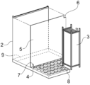
- FIG. 2 is a perspective view schematically showing the inside of the waste water treatment apparatus 10 of FIG. 1
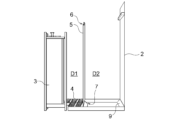
- FIG. 3 is a front view of the waste water treatment apparatus 10 of FIG. 2
- FIG. 4 is a course in the waste water treatment apparatus 10 of FIG. 5 is a rear view of the waste water treatment device 10 of FIG. 2
- FIG. 6 is a left side view of the waste water treatment device 10 of FIG. 2 viewed from the direction of the denitrification reaction zone D2.
- FIG. 7 is a right side view of the waste water treatment apparatus 10 of FIG. 2 viewed from the direction of the nitrification reaction area D1.
- the partition plate 5 has an overflow end 6 where the water to be treated overflows from the nitrification reaction zone D1 to the denitrification reaction zone D2, and an overflow end 6 where the water to be treated flows from the denitrification reaction zone D2 to the nitrification reaction zone D1. It has an opening 7 for moving to.
- the overflow end 6 may have a plurality of overflow points with different distances from the bottom of the reaction tank 2 in order to adjust the amount of overflow of the water to be treated.
- the opening 7 is provided in the partition plate 5 near the bottom of the reaction vessel 2 .
- the opening 7 serves as an air diffuser 4 for diffusing air into the nitrification reaction area D1 in order to prevent the water to be treated in which oxygen is dissolved in the nitrification reaction area D1 from flowing back to the denitrification reaction area D2. It is preferable that the diffuser plate is provided closer to the bottom side of the reaction tank than the diffuser plate and that the opening area is small.
- the area of the opening 7 may be 0.3 to 3.5% of the substantial area of the partition plate 5, that is, the area of the partition plate 5 itself excluding the opening 7.
- the opening 7 is preferably remote from the membrane separation device 3 in order to prevent the water to be treated that has moved from the denitrification reaction region D2 to the nitrification reaction region D1 from entering the membrane separation device 3 immediately.
- the membrane separator 3 and the opening 7 are arranged diagonally at the bottom of the nitrification reaction zone D1 of the reaction tank 2 .
- the water to be treated overflows the overflow end 6 of the partition plate 5 and moves from the nitrification reaction region D1 to the denitrification reaction region D2, Via the opening 7, the denitrification reaction zone D2 returns to the nitrification reaction zone D1. Thereby, a circulation flow that circulates around the partition plate 5 is formed. Therefore, the nitrous acid and nitric acid generated in the nitrification reaction area D1 move to the denitrification reaction area D2 and are converted into nitrogen in the denitrification reaction area D2.
- the overflow end 6 and the opening 7 are arranged diagonally on the partition plate 5 . Since the amount of waste water overflowing is the largest in the upper part of the overflow end 6, by arranging the overflow end 6 and the opening 7 on a diagonal line, circulation having a mixed state necessary for the nitrification reaction and the denitrification reaction is achieved. It is possible to effectively form a stream and perform efficient wastewater treatment.
- the opening 7 is provided closer to the bottom side of the reaction tank 2 than the air diffuser 4, and an upward flow is formed by air bubbles diffused from the air diffuser 4 in the nitrification reaction zone D1. ing. Therefore, when the water level of the waste water is higher than the upper end of the partition plate 5 and the circulation flow is formed around the partition plate 5, most of the water to be treated that flows into the nitrification reaction area D1 from the opening 7 is dispersed. It passes through the gas device 4 and moves to the upper nitrification reaction region D1, and the rest forms a short-circuit flow moving in the region between the bottom of the reaction tank 2 and the gas diffuser 4 in the direction of the membrane separation device 3.
- the short-circuit flow is a local flow having a residence time different from that of the circulating flow formed around the partition plate 5 .
- FIG. 4 is an enlarged view of the path changing member 8 (the air diffuser 4 is omitted) in the waste water treatment apparatus 10 of FIG.
- the path-changing member 8 is arranged between the membrane separation device 3 and the air diffuser 4, and when the short-circuit flow contacts the path-changing member 8, it changes its course upward in the vertical direction and changes to an upward flow.
- the bottom of the housing of the membrane separation device 3 is open, but the sides of the housing are covered with a plate-shaped member, so the upward flow that has changed from the short-circuit flow reaches the housing in which the hollow fiber membranes are installed. Cannot enter inside.
- the short-circuit flow includes treated water that has undergone nitrification and denitrification reactions, and water to be treated containing ammonia supplied from the water tank 1 to be treated.
- a haunch having an inclined surface inclined with a certain gradient is used for the course changing member 8.
- the haunch When the haunch is installed, the slanted surface faces the air diffuser 4, and the short-circuit flow toward the membrane separator 3 contacts the slanted surface and changes course.
- the inclination of the inclined surface of the haunch may not be constant, and the inclined surface may be composed of a concave curved surface.
- the height of the upper end of the path changing member 8 may be such that the upward flow changed from the short-circuit flow does not enter the housing from the opening at the bottom of the housing of the membrane separation device 3.
- the hollow fiber is separated from the lower end of the hollow fiber membrane in the membrane separation device 3 to 1 ⁇ 3 of the height of the hollow fiber membrane, preferably from the lower end of the hollow fiber membrane. It is preferred that the position is up to 1/5 of the height of the membrane.
- the course changing member 8 for example, a rotating body is used.
- the rotating body which is the path changing member 8 rotates, an upward flow is formed between the membrane separation device 3 and the air diffuser 4, so the short-circuit flow is taken into the upward flow previously formed by the rotating body, As a result, it changes to an upward flow.
- the rotating body since the rotating body requires additional power, it is preferable to use a haunch that is simply installed as the course changing member 8 .
- the path changing member 8 is not limited to the embossed haunches and rotating bodies as long as it obstructs the path of the short-circuit flow from the opening 7 to the membrane separation device 3 .
- Diverting members 8, e.g. haunches, are arranged between the diffuser 4 and the walls of the reactor 2 and between the diffuser 4 and the partition plate 5 at the bottom of the reactor 2 in the nitrification reaction zone D1. Alternatively, it may be arranged at the periphery of the bottom of the reaction vessel 2 in the denitrification reaction zone D2. As a result, the sludge sedimentation prevention member 9 is formed, and the sedimentation of activated sludge in one corner of the bottom of the reaction tank 2 can be avoided, and the efficiency of wastewater treatment using activated sludge can be improved.
- the haunch used as the path-changing member 8 and the haunch (sludge anti-settling member 9) used not as the path-changing member 8 but to prevent settling of the activated sludge may be integrally formed. As a result, it is only necessary to install the integrally formed haunches in the reaction vessel 2, and the trouble of installing each haunch individually can be saved.
- the ascending flow formed by the path changing member 8 undergoes a nitrification reaction in the nitrification reaction zone D1 where oxygen supplied from the air diffuser 4 exists, and the ammonia contained in the ascending flow is converted to nitrous acid or nitric acid. .
- the water to be treated containing nitrous acid or nitric acid generated by conversion of ammonia overflows the overflow end 6 of the partition plate 5, moves to the denitrification reaction zone D2, and is subjected to the denitrification reaction.
- the treated water that has undergone the nitrification reaction and the denitrification reaction and has flowed into the nitrification reaction area D1 from the opening 3 rises in the nitrification reaction area D1 and then descends to the opening at the bottom of the casing of the membrane separation device 3.
- the hollow fiber membrane By entering the inside of the housing through the hollow fiber membrane, it is discharged to the outside of the reaction vessel 2 .
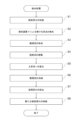
- FIG. 8 is a flow chart showing the procedure of waste water treatment performed by the waste water treatment apparatus 10 of FIG.
- the water to be treated is supplied from the water tank 1 to be treated to the reaction tank 2 (S1), and when the water level of the water to be treated in the reaction tank 2 reaches the highest water level HWL. Then, the pump P1 is stopped, and the air diffuser 4 diffuses minute air bubbles (S2). As a result, the water to be treated in the nitrification reaction area D1 overflows the overflow end 6 and moves to the denitrification reaction area D2, and returns from the denitrification reaction area D2 to the nitrification reaction area D1 via the opening 7. (Moving step), a circulating flow circulating around the partition plate 5 is formed (S3).
- the water to be treated undergoes nitrification reaction in the nitrification reaction zone D1, and the water to be treated undergoes denitrification reaction in the denitrification reaction zone D2. This produces treated water.
- the water to be treated moves from the denitrification reaction zone D2 to the nitrification reaction zone D1.
- part of the water to be treated that has entered the nitrification reaction area D1 through the opening 7 forms a short-circuit flow in the area between the bottom of the reaction tank 2 and the air diffuser 4, and the membrane separation apparatus 3 (S4, advance step), but contact with the path changing member 8 and change to an upward flow rising from the bottom of the reaction tank 2 toward the water surface of the water to be treated (S5, path changing step).
- the ascending flow undergoes a nitrification reaction in the nitrification reaction zone D1 where oxygen supplied from the air diffuser 4 exists, and the ammonia contained in the ascending flow is converted to nitrous acid or nitric acid.
- the water to be treated containing nitrous acid or nitric acid generated by conversion of ammonia overflows the overflow end 6 of the partition plate 5, moves to the denitrification reaction zone D2, and is subjected to the denitrification reaction.
- the produced treated water is discharged to the outside of the reaction tank 2 via the membrane separation device 3 .
- the water level of the water to be treated drops and is positioned between the overflow end 6 and the lowest water level LWL, and the circulation flow disappears (S6).
- the circulation flow disappears (S6).
- the water to be treated is subjected to nitrification reaction in the nitrification reaction zone D1
- the water to be treated is subjected to denitrification reaction in the denitrification reaction zone D2.
- the treated water is discharged to the outside of the reaction tank 2 via the membrane separation device 3 (S7).
- the water level of the water to be treated reaches the lowest water level LWL, and the pump P1 is driven to supply new water to be treated from the water tank 1 to be treated to the reaction tank 2 (S8), and this process ends.
- the water to be treated that has entered the nitrification reaction area D1 via the opening 7 forms a short-circuit flow and moves toward the membrane separation device 3 (S4).
- the short-circuit flow comes into contact with the path changing member 8 and changes into an upward flow rising from the bottom of the reaction tank 2 toward the water surface of the water to be treated (S5).
- the water to be treated which has just been supplied from the water tank to be treated 1 to the reaction tank 2 and has not been treated with activated sludge can be prevented from directly entering the interior of the membrane separation device 3. It is possible to prevent ammonia from being immediately discharged to the outside of the reaction tank 2 without being removed from the water to be treated. As a result, wastewater treatment can be performed appropriately.
Landscapes
- Life Sciences & Earth Sciences (AREA)
- Microbiology (AREA)
- Hydrology & Water Resources (AREA)
- Engineering & Computer Science (AREA)
- Environmental & Geological Engineering (AREA)
- Water Supply & Treatment (AREA)
- Chemical & Material Sciences (AREA)
- Organic Chemistry (AREA)
- Biodiversity & Conservation Biology (AREA)
- Separation Using Semi-Permeable Membranes (AREA)
- Purification Treatments By Anaerobic Or Anaerobic And Aerobic Bacteria Or Animals (AREA)
Abstract
The present invention provides a wastewater treatment apparatus 10 capable of appropriately performing wastewater treatment. The wastewater treatment apparatus 10, for performing a nitrification reaction which converts ammonia contained in wastewater into nitrous acid or nitric acid in the presence of oxygen, and a denitrification reaction which converts nitrous acid or nitric acid generated by the nitrification reaction into nitrogen in the absence of oxygen, comprises: a partition board 5 which separates a nitrification reaction region D1 for performing the nitrification reaction and a denitrification reaction region D2 for performing the denitrification reaction; a membrane separation apparatus 3 which is installed in the nitrification reaction region D1 and separates and removes solids contained in wastewater; and a path changing member 8 which changes the path of wastewater moving from the denitrification reaction region D2 to the nitrification reaction region D1 toward the membrane separation apparatus 3.
Description
本発明は排水処理装置及び排水処理方法に関する。
The present invention relates to a wastewater treatment device and a wastewater treatment method.
従来より、排水に含まれるアンモニアを酸素存在下において微生物を含む有機汚泥(以下、「活性汚泥」という)である硝化菌が亜硝酸や硝酸に変換する硝化反応と、亜硝酸や硝酸を無酸素状態で活性汚泥である脱窒菌が窒素に変換する脱窒反応と、を単一の反応槽で実行する排水処理装置が知られている(例えば、特許文献1参照)。特許文献1の排水処理装置において、反応槽は、硝化反応を実行する硝化反応領域と、脱窒反応を実行する脱窒反応領域と、に区分する仕切板を備え、硝化反応領域は硝化反応及び脱窒反応が実行された排水(以下、「処理済水」という。)に含まれる固形分を分離除去する膜分離装置と、膜分離装置の表面を洗浄し又は硝化反応に必要な空気を供給するための気泡を散気する散気装置と、を有する。
Conventionally, nitrifying bacteria, organic sludge containing microorganisms (hereinafter referred to as "activated sludge"), convert ammonia contained in wastewater into nitrous acid and nitric acid in the presence of oxygen. A wastewater treatment apparatus is known in which a denitrifying reaction in which denitrifying bacteria, which are activated sludge in a state, converts to nitrogen, and a denitrifying reaction are performed in a single reaction tank (see, for example, Patent Document 1). In the wastewater treatment apparatus of Patent Document 1, the reaction tank includes a partition plate that divides the nitrification reaction zone for carrying out the nitrification reaction and the denitrification reaction zone for carrying out the denitrification reaction. A membrane separator that separates and removes solids contained in wastewater that has undergone denitrification (hereinafter referred to as "treated water"), and a membrane separator that cleans the surface or supplies air necessary for the nitrification reaction. and an air diffuser for diffusing air bubbles.
排水の水位が仕切板の上端よりも高いとき、排水は仕切板を越流して硝化反応領域から脱窒反応領域に移動するとともに、脱窒反応領域から硝化反応領域に戻る。これにより、仕切板の周囲を循環する循環流が形成される。したがって、硝化反応領域において生成された亜硝酸や硝酸は脱窒反応領域に移動し、脱窒反応領域において窒素に変換される。一方、排水の水位が仕切板の上端よりも低いとき、排水は仕切板を越流しない。したがって、循環流は形成されず、硝化反応領域では亜硝酸や硝酸が生成され、脱窒反応領域では予め硝化反応領域から脱窒反応領域に移動した亜硝酸や硝酸が窒素に変換される。
When the water level of the wastewater is higher than the upper end of the partition plate, the wastewater overflows the partition plate and moves from the nitrification reaction area to the denitrification reaction area and returns from the denitrification reaction area to the nitrification reaction area. As a result, a circulation flow that circulates around the partition plate is formed. Therefore, nitrous acid and nitric acid produced in the nitrification reaction zone move to the denitrification reaction zone and are converted to nitrogen in the denitrification reaction zone. On the other hand, when the water level of the waste water is lower than the upper end of the partition plate, the waste water does not overflow the partition plate. Therefore, a circulation flow is not formed, nitrous acid and nitric acid are produced in the nitrification reaction zone, and the nitrous acid and nitric acid that have previously moved from the nitrification reaction zone to the denitrification reaction zone are converted into nitrogen in the denitrification reaction zone.
膜分離装置は複数の長尺状の中空糸膜を有し、中空糸膜の下端部が反応槽の底部に設置されているとき、各中空糸膜の長手方向は鉛直方向に沿っている。処理済水は中空糸膜の内部に進入し、鉛直方向において上向きに上昇して反応槽の外部に排出される。これにより、反応槽内部の排水の水位は低下する。反応槽には水位センサーが設置され、水位センサーは反応槽内部の排水の水位が予め設定されている最低水位に到達したことを検出したとき、処理される前の排水である被処理水が反応槽の脱窒反応領域に導入される。
The membrane separation device has a plurality of elongated hollow fiber membranes, and when the lower ends of the hollow fiber membranes are placed on the bottom of the reaction tank, the longitudinal direction of each hollow fiber membrane is along the vertical direction. The treated water enters the interior of the hollow fiber membrane, rises vertically, and is discharged to the outside of the reactor. As a result, the water level of the waste water inside the reaction tank is lowered. A water level sensor is installed in the reaction tank, and when the water level sensor detects that the water level of the waste water inside the reaction tank has reached the preset minimum water level, the water to be treated, which is waste water before being treated, reacts. It is introduced into the denitrification reaction zone of the tank.
ところで、散気装置から散気される気泡が硝化反応領域に供給されるとともに、脱窒反応領域に供給されないために、反応槽の底部及び仕切板の間の開口部は、例えば、散気装置よりも反応槽の底部側に形成されている。
By the way, since the air bubbles diffused from the air diffuser are supplied to the nitrification reaction area and not supplied to the denitrification reaction area, the opening between the bottom of the reaction tank and the partition plate is more difficult than the air diffuser, for example. It is formed on the bottom side of the reactor.
しかしながら、膜分離装置の周囲には散気装置から散気される気泡の影響により、上昇流が形成されるとともに、反応槽の底部及び散気装置の間に短絡流が形成される。これにより、開口部周辺の排水は膜分離装置の底部に移動する。したがって、被処理水が反応槽の脱窒反応領域に供給され、開口部を経て硝化反応領域にある膜分離装置の底部に移動し、膜分離装置によって反応槽の外部に排出される場合がある。この場合、被処理水からアンモニアは除去されず、排水処理を適切に実行することができないという問題があった。
However, due to the influence of air bubbles diffused from the air diffuser, an upward flow is formed around the membrane separator, and a short-circuit flow is formed between the bottom of the reaction tank and the air diffuser. As a result, the wastewater around the opening moves to the bottom of the membrane separator. Therefore, the water to be treated may be supplied to the denitrification reaction zone of the reaction tank, move through the opening to the bottom of the membrane separation device in the nitrification reaction zone, and be discharged to the outside of the reaction tank by the membrane separation device. . In this case, there is a problem that ammonia is not removed from the water to be treated, and the wastewater treatment cannot be performed properly.
本発明は、排水処理を適切に実行することができる排水処理装置及び排水処理方法を提供することを目的とする。
An object of the present invention is to provide a wastewater treatment apparatus and a wastewater treatment method that can properly perform wastewater treatment.
上記目的を達成するために、本発明の排水処理装置は、排水に含まれるアンモニアを酸素存在下において亜硝酸又は硝酸に変換する硝化反応と、前記硝化反応に基づいて生成された亜硝酸又は硝酸を無酸素状態において窒素に変換する脱窒反応と、を実行する排水処理装置において、前記硝化反応を実行する硝化反応領域及び前記脱窒反応を実行する脱窒反応領域を区分する区分手段と、前記硝化反応領域に設置され、排水に含まれる固形分を分離除去する膜分離手段と、前記脱窒反応領域から前記硝化反応領域に移動し、前記膜分離手段に向かう排水の進路を変更する進路変更手段と、を備えることを特徴とする。
In order to achieve the above object, the wastewater treatment apparatus of the present invention comprises a nitrification reaction for converting ammonia contained in wastewater into nitrous acid or nitric acid in the presence of oxygen, and nitrous acid or nitric acid produced based on the nitrification reaction. a denitrification reaction that converts to nitrogen in anoxic conditions, in a wastewater treatment apparatus for performing a nitrification reaction zone for carrying out the nitrification reaction and a denitrification reaction zone for carrying out the denitrification reaction; Membrane separation means installed in the nitrification reaction zone for separating and removing solids contained in the wastewater, and a course for changing the course of the wastewater moving from the denitrification reaction zone to the nitrification reaction zone and heading for the membrane separation means. and changing means.
上記目的を達成するために、本発明の排水処理方法は、排水に含まれるアンモニアを酸素存在下において亜硝酸又は硝酸に変換する硝化反応と、前記硝化反応に基づいて生成された亜硝酸又は硝酸を無酸素状態において窒素に変換する脱窒反応と、を実行する排水処理方法において、前記排水が前記脱窒反応を実行する脱窒反応領域から前記硝化反応を実行する硝化反応領域に移動する移動ステップと、前記硝化反応領域に移動した排水が、前記硝化反応領域に設置され、排水に含まれる固形分を分離除去する膜分離手段に向かう進行ステップと、前記膜分離手段に向かう排水の進路を変更する進路変更ステップと、を有することを特徴とする。
In order to achieve the above object, the wastewater treatment method of the present invention comprises a nitrification reaction for converting ammonia contained in wastewater into nitrous acid or nitric acid in the presence of oxygen, and nitrous acid or nitric acid produced based on the nitrification reaction. to nitrogen in anoxic conditions, wherein said wastewater moves from a denitrification reaction zone where said denitrification reaction is carried out to a nitrification reaction zone where said nitrification reaction is carried out. a step of advancing the waste water that has moved to the nitrification reaction zone to a membrane separation means installed in the nitrification reaction zone to separate and remove solids contained in the waste water; and a course change step for changing.
本発明によれば、排水処理を適切に実行することができる。
According to the present invention, wastewater treatment can be performed appropriately.
以下、本発明の実施の形態について図面を参照しながら詳述する。
Hereinafter, embodiments of the present invention will be described in detail with reference to the drawings.
図1は、本発明の実施の形態に係る排水処理装置10の概略図である。
FIG. 1 is a schematic diagram of a waste water treatment device 10 according to an embodiment of the present invention.
図1の排水処理装置10は被処理水槽1、反応槽2、ポンプP1,P2、液面センサーLS、ブロワBを備え、反応槽2は膜分離装置3(膜分離手段)、散気装置4(酸素供給手段)、仕切板5(区分手段)を有する。被処理水槽1及びポンプP1、ポンプP1及び液面センサーLS、ブロワB及び散気装置4、並びに、ポンプP2及び膜分離装置3が接続されている。
The wastewater treatment apparatus 10 of FIG. (oxygen supply means) and a partition plate 5 (dividing means). A water tank 1 to be treated and a pump P1, a pump P1 and a liquid level sensor LS, a blower B and an air diffuser 4, and a pump P2 and a membrane separation device 3 are connected.
被処理水槽1は反応槽2に供給されて処理される被処理水(原水)を貯留し、被処理水は反応槽2の槽内に供給される。反応槽2では被処理水槽1から供給された被処理水に、被処理水に含まれるアンモニアを酸素存在下において亜硝酸や硝酸に変換する硝化反応及び亜硝酸や硝酸を無酸素状態で窒素に変換する脱窒反応が施される。硝化反応は活性汚泥である硝化菌によって実行され、脱窒反応は活性汚泥である脱窒菌によって実行される。
The water tank 1 to be treated stores the water to be treated (raw water) that is supplied to the reaction tank 2 and treated, and the water to be treated is supplied into the reaction tank 2 . In the reaction tank 2, the water to be treated supplied from the water tank 1 to be treated undergoes a nitrification reaction that converts ammonia contained in the water to nitrous acid and nitric acid in the presence of oxygen, and nitrite and nitric acid to nitrogen in an oxygen-free state. A transforming denitrification reaction is applied. The nitrification reaction is carried out by activated sludge nitrifying bacteria, and the denitrification reaction is carried out by activated sludge denitrifying bacteria.
反応槽2には被処理水槽1からの被処理水の供給を停止する最高水位HWL及び被処理水槽1からの被処理水の供給を開始する最低水位LWLが設定され、例えば、液面センサーLSが被処理水の水位に関して最低水位LWLを検出したとき、ポンプP1が駆動して被処理水槽1から反応槽2への被処理水の供給が開始され、液面センサーLSが被処理水の水位に関して最高水位HWLを検出したとき、ポンプP1が停止して被処理水槽1から反応槽2への被処理水の供給が停止される。
A maximum water level HWL at which the supply of water to be treated from the water tank 1 is stopped and a minimum water level LWL at which the supply of water to be treated from the water tank 1 is started are set in the reaction tank 2. For example, a liquid level sensor LS detects the lowest water level LWL of the water to be treated, the pump P1 is driven to start supplying the water to be treated from the water tank 1 to the reaction tank 2, and the liquid level sensor LS detects the water level of the water to be treated. When the highest water level HWL is detected, the pump P1 is stopped and the supply of the water to be treated from the water tank 1 to be treated to the reaction tank 2 is stopped.
ポンプP2が駆動すると、硝化反応及び脱窒反応が施された処理済水は膜分離装置3を経由して反応槽2の槽外に排出される。膜分離装置3は、反応槽2に設置されたときに鉛直方向に関して延伸する直方体状の筐体と、筐体の内部に設置された複数の中空糸膜とを有する。膜分離装置3の筐体の4つの側面はそれぞれ分割可能な長尺状の板状部材により構成されており、筐体の底部は開口している。処理済水は膜分離装置3の筐体の底部から筐体の内部に進入し、中空糸膜の表面から中空糸膜の内部に移行する。処理済水に含まれる固形分は膜分離装置3を経由するときに分離除去される。反応槽2の底部及び膜分離装置3の間には不図示の散気装置が設置されている。不図示の散気装置は膜分離装置3に空気を供給し、その空気は膜分離装置3の中空糸膜の表面に衝突して膜分離装置3を洗浄し、膜分離装置3の中空糸膜のファウリングを抑制する。
When the pump P2 is driven, the treated water that has undergone the nitrification reaction and the denitrification reaction is discharged outside the reaction tank 2 via the membrane separation device 3. The membrane separation device 3 has a rectangular parallelepiped housing that extends in the vertical direction when installed in the reaction vessel 2, and a plurality of hollow fiber membranes installed inside the housing. The four side surfaces of the housing of the membrane separation device 3 are made up of dividable elongated plate-like members, and the bottom of the housing is open. The treated water enters the housing from the bottom of the housing of the membrane separation device 3 and moves from the surface of the hollow fiber membrane to the interior of the hollow fiber membrane. Solids contained in the treated water are separated and removed when passing through the membrane separator 3 . An air diffuser (not shown) is installed between the bottom of the reaction vessel 2 and the membrane separation device 3 . An air diffuser (not shown) supplies air to the membrane separation device 3, and the air collides with the surface of the hollow fiber membranes of the membrane separation device 3 to wash the membrane separation device 3. inhibits fouling.
ブロワBは散気装置4に空気を供給する。これにより、散気装置4は、例えば、空気径20~500μmの微小な空気を、散気装置4が有する散気板から硝化反応を実行する硝化反応領域D1に多量に散気し、硝化反応に必要な酸素を供給する。本実施の形態において、散気装置4は硝化反応領域D1において膜分離装置3とは異なる領域に配置される。仕切板5は反応槽2を硝化反応領域D1と、脱窒反応を実行する脱窒反応領域D2と、に区分する。
The blower B supplies air to the air diffuser 4. As a result, the air diffuser 4 diffuses a large amount of fine air having an air diameter of 20 to 500 μm, for example, from the diffuser plate of the air diffuser 4 to the nitrification reaction area D1 where the nitrification reaction is performed. supply the oxygen it needs. In the present embodiment, the air diffuser 4 is arranged in a region different from the membrane separation device 3 in the nitrification reaction region D1. The partition plate 5 divides the reaction tank 2 into a nitrification reaction area D1 and a denitrification reaction area D2 in which the denitrification reaction is performed.
図2は図1の排水処理装置10の内部を概略的に示す斜視図であり、図3は図2の排水処理装置10の正面図であり、図4は図3の排水処理装置10における進路変更部材8の拡大図であり、図5は図2の排水処理装置10の背面図であり、図6は図2の排水処理装置10を脱窒反応領域D2の方向から眺めた左側面図であり、図7は図2の排水処理装置10を硝化反応領域D1の方向から眺めた右側面図である。
2 is a perspective view schematically showing the inside of the waste water treatment apparatus 10 of FIG. 1, FIG. 3 is a front view of the waste water treatment apparatus 10 of FIG. 2, and FIG. 4 is a course in the waste water treatment apparatus 10 of FIG. 5 is a rear view of the waste water treatment device 10 of FIG. 2, and FIG. 6 is a left side view of the waste water treatment device 10 of FIG. 2 viewed from the direction of the denitrification reaction zone D2. FIG. 7 is a right side view of the waste water treatment apparatus 10 of FIG. 2 viewed from the direction of the nitrification reaction area D1.
図2乃至図7において、仕切板5は被処理水が硝化反応領域D1から脱窒反応領域D2に越流する越流端部6と、被処理水が脱窒反応領域D2から硝化反応領域D1に移動するための開口部7を有する。越流端部6は被処理水の越流量を調整するために、反応槽2の底部からの距離が異なる複数の越流箇所を有していてもよい。
2 to 7, the partition plate 5 has an overflow end 6 where the water to be treated overflows from the nitrification reaction zone D1 to the denitrification reaction zone D2, and an overflow end 6 where the water to be treated flows from the denitrification reaction zone D2 to the nitrification reaction zone D1. It has an opening 7 for moving to. The overflow end 6 may have a plurality of overflow points with different distances from the bottom of the reaction tank 2 in order to adjust the amount of overflow of the water to be treated.
開口部7は仕切板5において反応槽2の底部近傍に設けられている。開口部7は、硝化反応領域D1の酸素が溶存している被処理水が脱窒反応領域D2に逆流するのを防止するために、硝化反応領域D1に空気を散気する散気装置4の散気板よりも反応槽の底部側に設けられ且つ開口面積が小さいのがよい。開口部7の面積は仕切板5の実質的な面積、すなわち、開口部7を除く仕切板5自体の面積の0.3~3.5%であればよい。このような小さい開口面積とすることにより、開口部7を通過する被処理水の流速を速め、開口部7の周辺に活性汚泥が滞留することを防ぐことができる。また、開口部7は脱窒反応領域D2から硝化反応領域D1に移動した被処理水が直ちに膜分離装置3に進入するのを防止するために、膜分離装置3の遠隔であるのがよい。本実施の形態において、膜分離装置3及び開口部7は反応槽2の硝化反応領域D1の底部において対角線上に配置されている。
The opening 7 is provided in the partition plate 5 near the bottom of the reaction vessel 2 . The opening 7 serves as an air diffuser 4 for diffusing air into the nitrification reaction area D1 in order to prevent the water to be treated in which oxygen is dissolved in the nitrification reaction area D1 from flowing back to the denitrification reaction area D2. It is preferable that the diffuser plate is provided closer to the bottom side of the reaction tank than the diffuser plate and that the opening area is small. The area of the opening 7 may be 0.3 to 3.5% of the substantial area of the partition plate 5, that is, the area of the partition plate 5 itself excluding the opening 7. With such a small opening area, the flow velocity of the water to be treated passing through the opening 7 can be increased, and activated sludge can be prevented from remaining around the opening 7 . Further, the opening 7 is preferably remote from the membrane separation device 3 in order to prevent the water to be treated that has moved from the denitrification reaction region D2 to the nitrification reaction region D1 from entering the membrane separation device 3 immediately. In this embodiment, the membrane separator 3 and the opening 7 are arranged diagonally at the bottom of the nitrification reaction zone D1 of the reaction tank 2 .
排水の水位が仕切板5の上端よりも高いとき、被処理水は仕切板5の越流端部6を越流して硝化反応領域D1から脱窒反応領域D2に移動するとともに、仕切板5の開口部7を経由して脱窒反応領域D2から硝化反応領域D1に戻る。これにより、仕切板5の周囲を循環する循環流が形成される。したがって、硝化反応領域D1において生成された亜硝酸や硝酸は脱窒反応領域D2に移動し、脱窒反応領域D2において窒素に変換される。
When the water level of the wastewater is higher than the upper end of the partition plate 5, the water to be treated overflows the overflow end 6 of the partition plate 5 and moves from the nitrification reaction region D1 to the denitrification reaction region D2, Via the opening 7, the denitrification reaction zone D2 returns to the nitrification reaction zone D1. Thereby, a circulation flow that circulates around the partition plate 5 is formed. Therefore, the nitrous acid and nitric acid generated in the nitrification reaction area D1 move to the denitrification reaction area D2 and are converted into nitrogen in the denitrification reaction area D2.
本実施の形態において、越流端部6と開口部7は仕切板5において対角線上に配置されている。越流端部6の上部は排水の越流量が最も多くなるため、越流端部6と開口部7を対角線上に配置することにより、硝化反応と脱窒反応に必要な混合状態を有する循環流を効果的に形成し、効率的な排水処理を行うことができる。
In this embodiment, the overflow end 6 and the opening 7 are arranged diagonally on the partition plate 5 . Since the amount of waste water overflowing is the largest in the upper part of the overflow end 6, by arranging the overflow end 6 and the opening 7 on a diagonal line, circulation having a mixed state necessary for the nitrification reaction and the denitrification reaction is achieved. It is possible to effectively form a stream and perform efficient wastewater treatment.
一方、排水の水位が仕切板5の上端よりも低いとき、排水は仕切板5を越流しない。したがって、循環流は形成されず、硝化反応領域D1では亜硝酸や硝酸が生成され、脱窒反応領域D2では予め硝化反応領域D1から脱窒反応領域D2に移動した亜硝酸や硝酸が窒素に変換される。
On the other hand, when the water level of the drainage is lower than the upper end of the partition plate 5, the drainage does not overflow the partition plate 5. Therefore, no circulating flow is formed, nitrous acid and nitric acid are generated in the nitrification reaction zone D1, and in the denitrification reaction zone D2, the nitrous acid and nitric acid that have previously moved from the nitrification reaction zone D1 to the denitrification reaction zone D2 are converted into nitrogen. be done.
本実施の形態では、開口部7が散気装置4よりも反応槽2の底部側に設けられ、且つ、硝化反応領域D1において散気装置4から散気される気泡により上向流が形成されている。そのため、排水の水位が仕切板5の上端よりも高く、仕切板5の周囲に循環流が形成されているときに開口部7から硝化反応領域D1に流入した被処理水は、大部分は散気装置4を通過して上部の硝化反応領域D1に移行し、残りは反応槽2の底部と散気装置4との間の領域を膜分離装置3の方向に移動する短絡流を形成する。ここで、短絡流とは仕切板5の周囲に形成された循環流の滞留時間とは異なる滞留時間を有する局部的な流れである。
In the present embodiment, the opening 7 is provided closer to the bottom side of the reaction tank 2 than the air diffuser 4, and an upward flow is formed by air bubbles diffused from the air diffuser 4 in the nitrification reaction zone D1. ing. Therefore, when the water level of the waste water is higher than the upper end of the partition plate 5 and the circulation flow is formed around the partition plate 5, most of the water to be treated that flows into the nitrification reaction area D1 from the opening 7 is dispersed. It passes through the gas device 4 and moves to the upper nitrification reaction region D1, and the rest forms a short-circuit flow moving in the region between the bottom of the reaction tank 2 and the gas diffuser 4 in the direction of the membrane separation device 3. Here, the short-circuit flow is a local flow having a residence time different from that of the circulating flow formed around the partition plate 5 .
反応槽2の底部には、開口部7から硝化反応領域D1に進入した被処理水が反応槽2の底部及び散気装置4の間を通過して膜分離装置3に向かう短絡流の進路を変更する進路変更部材8(進路変更手段)が配置されている。図4は、図3の排水処理装置10における進路変更部材8の拡大図(散気装置4は省略)である。進路変更部材8は膜分離装置3及び散気装置4の間に配置され、当該短絡流は進路変更部材8に接触したとき、進路を鉛直方向において上向きに変更し、上昇流に変化する。膜分離装置3の筐体の底部は開口しているが、筐体の側面は板状部材により覆われているため、短絡流から変化した上昇流は中空糸膜が設置されている筐体の内部に進入することができない。短絡流には硝化反応及脱窒反応が実行された処理済水と、被処理水槽1から供給されたアンモニアを含む被処理水が含まれているが、進路変更部材8を膜分離装置3と散気装置4の間に配置して、進路変更部材8に接触した短絡流を上昇流に変化させることにより、アンモニアが硝化反応を施されることなく膜分離装置3の筐体内部に進入し中空糸膜に接触するのを防止することができる。
At the bottom of the reaction tank 2, the water to be treated, which has entered the nitrification reaction zone D1 through the opening 7, passes between the bottom of the reaction tank 2 and the air diffuser 4 to form a short-circuit flow path toward the membrane separation device 3. A changing course changing member 8 (a course changing means) is arranged. FIG. 4 is an enlarged view of the path changing member 8 (the air diffuser 4 is omitted) in the waste water treatment apparatus 10 of FIG. The path-changing member 8 is arranged between the membrane separation device 3 and the air diffuser 4, and when the short-circuit flow contacts the path-changing member 8, it changes its course upward in the vertical direction and changes to an upward flow. The bottom of the housing of the membrane separation device 3 is open, but the sides of the housing are covered with a plate-shaped member, so the upward flow that has changed from the short-circuit flow reaches the housing in which the hollow fiber membranes are installed. Cannot enter inside. The short-circuit flow includes treated water that has undergone nitrification and denitrification reactions, and water to be treated containing ammonia supplied from the water tank 1 to be treated. By placing between the air diffusers 4 and changing the short-circuit flow in contact with the path changing member 8 into an upward flow, the ammonia enters the housing of the membrane separation device 3 without undergoing a nitrification reaction. Contact with the hollow fiber membrane can be prevented.
進路変更部材8には、例えば、一定の勾配をもって傾斜する傾斜面を有するハンチが用いられる。ハンチが設置されているとき、傾斜面は散気装置4に対向し、膜分離装置3に向かう短絡流はその傾斜面に接触して進路を変更する。このような傾斜面を有するハンチを用いることにより、進路変更部材8と反応槽2の底面との間に活性汚泥が滞留するのを回避し、活性汚泥による排水処理の効率を高めることができる。ハンチの傾斜面の勾配は一定でなくてもよく、傾斜面が凹状の曲面から構成されていてもよい。進路変更部材8の上端部の高さは、短絡流から変化した上昇流が膜分離装置3の筐体底部の開口部から筐体内部に進入しない高さであればよいが、アンモニアを含む被処理水が排出されるのを効果的に防ぐため、膜分離装置3内の中空糸膜の下端部から中空糸膜の1/3の高さまで、好ましくは、中空糸膜の下端部から中空糸膜の1/5の高さまでの位置とするのがよい。
For the course changing member 8, for example, a haunch having an inclined surface inclined with a certain gradient is used. When the haunch is installed, the slanted surface faces the air diffuser 4, and the short-circuit flow toward the membrane separator 3 contacts the slanted surface and changes course. By using the haunch having such an inclined surface, it is possible to prevent the activated sludge from stagnation between the path changing member 8 and the bottom surface of the reaction tank 2, thereby increasing the efficiency of wastewater treatment with activated sludge. The inclination of the inclined surface of the haunch may not be constant, and the inclined surface may be composed of a concave curved surface. The height of the upper end of the path changing member 8 may be such that the upward flow changed from the short-circuit flow does not enter the housing from the opening at the bottom of the housing of the membrane separation device 3. In order to effectively prevent the treated water from being discharged, the hollow fiber is separated from the lower end of the hollow fiber membrane in the membrane separation device 3 to ⅓ of the height of the hollow fiber membrane, preferably from the lower end of the hollow fiber membrane. It is preferred that the position is up to 1/5 of the height of the membrane.
また、進路変更部材8には、例えば、回転体が用いられる。進路変更部材8である回転体が回転すると、膜分離装置3及び散気装置4の間に上昇流が形成されるので、当該短絡流は回転体によって予め形成された上昇流に取り込まれ、その結果、上昇流に変化する。なお、回転体は新たに動力が必要になるため、単に設置するだけのハンチが進路変更部材8として用いられるのがよい。すなわち、進路変更部材8は開口部7から膜分離装置3に向かう短絡流の進路が阻害されればよく、例示したハンチや回転体に限定されない。反応槽2において進路変更部材8を前述の開口部3と組み合わせて設けることにより、開口部3から硝化反応領域D1に流入し散気装置4と反応槽2の底部の間を移動する短絡流の進路を効果的に変更させ、アンモニアを含む被処理水が硝化反応を施される前に膜分離装置3に進入することを防ぐことができる。
Also, for the course changing member 8, for example, a rotating body is used. When the rotating body, which is the path changing member 8, rotates, an upward flow is formed between the membrane separation device 3 and the air diffuser 4, so the short-circuit flow is taken into the upward flow previously formed by the rotating body, As a result, it changes to an upward flow. In addition, since the rotating body requires additional power, it is preferable to use a haunch that is simply installed as the course changing member 8 . In other words, the path changing member 8 is not limited to the embossed haunches and rotating bodies as long as it obstructs the path of the short-circuit flow from the opening 7 to the membrane separation device 3 . By providing the path changing member 8 in combination with the opening 3 in the reaction tank 2, a short-circuit flow flowing from the opening 3 into the nitrification reaction zone D1 and moving between the air diffuser 4 and the bottom of the reaction tank 2 is formed. By effectively changing the course, it is possible to prevent the water to be treated containing ammonia from entering the membrane separation device 3 before undergoing the nitrification reaction.
進路変更部材8、例えば、ハンチは、硝化反応領域D1の反応槽2の底部において散気装置4及び反応槽2の壁の間、並びに、散気装置4及び仕切板5の間に配置されてもよく、脱窒反応領域D2の反応槽2の底部における周縁に配置されてもよい。これにより、汚泥沈降防止部材9が形成され、反応槽2の底部における一隅に活性汚泥が沈降するのを回避し、活性汚泥による排水処理の効率を高めることができる。進路変更部材8として用いられるハンチと、進路変更部材8としてではなく活性汚泥の沈降防止として用いられるハンチ(汚泥沈降防止部材9)と、は一体に形成されてもよい。これにより、一体に形成されたハンチを反応槽2に設置するだけでよく、各ハンチを個別に設置する手間を省くことができる。
Diverting members 8, e.g. haunches, are arranged between the diffuser 4 and the walls of the reactor 2 and between the diffuser 4 and the partition plate 5 at the bottom of the reactor 2 in the nitrification reaction zone D1. Alternatively, it may be arranged at the periphery of the bottom of the reaction vessel 2 in the denitrification reaction zone D2. As a result, the sludge sedimentation prevention member 9 is formed, and the sedimentation of activated sludge in one corner of the bottom of the reaction tank 2 can be avoided, and the efficiency of wastewater treatment using activated sludge can be improved. The haunch used as the path-changing member 8 and the haunch (sludge anti-settling member 9) used not as the path-changing member 8 but to prevent settling of the activated sludge may be integrally formed. As a result, it is only necessary to install the integrally formed haunches in the reaction vessel 2, and the trouble of installing each haunch individually can be saved.
進路変更部材8により形成された上昇流は、散気装置4から供給された酸素が存在する硝化反応領域D1において硝化反応が施され、上昇流に含まれるアンモニアが亜硝酸又は硝酸に変換される。アンモニアが変換して生成した亜硝酸又は硝酸を含む被処理水は、仕切板5の越流端部6を越流して脱窒反応領域D2に移動し脱窒反応に供される。また、開口部3から硝化反応領域D1に流入した硝化反応と脱窒反応が実行された処理済水は、硝化反応領域D1を上昇した後下降し、膜分離装置3の筐体底部の開口部から筐体内部に進入することにより、中空糸膜を経由して反応槽2の外部に排出される。
The ascending flow formed by the path changing member 8 undergoes a nitrification reaction in the nitrification reaction zone D1 where oxygen supplied from the air diffuser 4 exists, and the ammonia contained in the ascending flow is converted to nitrous acid or nitric acid. . The water to be treated containing nitrous acid or nitric acid generated by conversion of ammonia overflows the overflow end 6 of the partition plate 5, moves to the denitrification reaction zone D2, and is subjected to the denitrification reaction. In addition, the treated water that has undergone the nitrification reaction and the denitrification reaction and has flowed into the nitrification reaction area D1 from the opening 3 rises in the nitrification reaction area D1 and then descends to the opening at the bottom of the casing of the membrane separation device 3. By entering the inside of the housing through the hollow fiber membrane, it is discharged to the outside of the reaction vessel 2 .
図8は、図1の排水処理装置10によって実行される排水処理の手順を示すフローチャートである。
FIG. 8 is a flow chart showing the procedure of waste water treatment performed by the waste water treatment apparatus 10 of FIG.
図8の排水処理(排水処理方法)において、まず、被処理水が被処理水槽1から反応槽2に供給され(S1)、反応槽2の被処理水の水位が最高水位HWLに到達したときにポンプP1が停止され、散気装置4は微小な気泡を散気する(S2)。これにより、硝化反応領域D1の被処理水は越流端部6を越流して脱窒反応領域D2に移動するとともに、開口部7を経由して脱窒反応領域D2から硝化反応領域D1に戻り(移動ステップ)、仕切板5の周囲を循環する循環流が形成される(S3)。
In the wastewater treatment (wastewater treatment method) of FIG. 8, first, the water to be treated is supplied from the water tank 1 to be treated to the reaction tank 2 (S1), and when the water level of the water to be treated in the reaction tank 2 reaches the highest water level HWL. Then, the pump P1 is stopped, and the air diffuser 4 diffuses minute air bubbles (S2). As a result, the water to be treated in the nitrification reaction area D1 overflows the overflow end 6 and moves to the denitrification reaction area D2, and returns from the denitrification reaction area D2 to the nitrification reaction area D1 via the opening 7. (Moving step), a circulating flow circulating around the partition plate 5 is formed (S3).
循環流が形成されているとき、硝化反応領域D1では被処理水に対して硝化反応が施され、脱窒反応領域D2では被処理水に対して脱窒反応が施される。これにより、処理済水が生成される。ところで、循環流が形成されているとき、被処理水は脱窒反応領域D2から硝化反応領域D1に移動する。このとき、開口部7を経由して硝化反応領域D1に進入した被処理水の一部は反応槽2の底部と散気装置4との間の領域において短絡流を形成し、膜分離装置3に向けて移動する(S4、進行ステップ)が、進路変更部材8に接触して反応槽2の底部から被処理水の水面に向けて上昇する上昇流に変化する(S5、進路変更ステップ)。次いで、上昇流には散気装置4から供給された酸素が存在する硝化反応領域D1において硝化反応が施され、上昇流に含まれるアンモニアが亜硝酸又は硝酸に変換される。アンモニアが変換して生成した亜硝酸又は硝酸を含む被処理水は、仕切板5の越流端部6を越流して脱窒反応領域D2に移動し脱窒反応に供される。
When the circulation flow is formed, the water to be treated undergoes nitrification reaction in the nitrification reaction zone D1, and the water to be treated undergoes denitrification reaction in the denitrification reaction zone D2. This produces treated water. By the way, when the circulation flow is formed, the water to be treated moves from the denitrification reaction zone D2 to the nitrification reaction zone D1. At this time, part of the water to be treated that has entered the nitrification reaction area D1 through the opening 7 forms a short-circuit flow in the area between the bottom of the reaction tank 2 and the air diffuser 4, and the membrane separation apparatus 3 (S4, advance step), but contact with the path changing member 8 and change to an upward flow rising from the bottom of the reaction tank 2 toward the water surface of the water to be treated (S5, path changing step). Next, the ascending flow undergoes a nitrification reaction in the nitrification reaction zone D1 where oxygen supplied from the air diffuser 4 exists, and the ammonia contained in the ascending flow is converted to nitrous acid or nitric acid. The water to be treated containing nitrous acid or nitric acid generated by conversion of ammonia overflows the overflow end 6 of the partition plate 5, moves to the denitrification reaction zone D2, and is subjected to the denitrification reaction.
生成された処理済水は膜分離装置3を経由して反応槽2の外部に排出される。処理済水が反応槽2の外部に排出されると、被処理水の水位は下降して越流端部6及び最低水位LWLの間に位置し、循環流は消滅する(S6)。循環流が形成されていないときも、また、硝化反応領域D1では被処理水に対して硝化反応が施され、脱窒反応領域D2では被処理水に対して脱窒反応が施される。
The produced treated water is discharged to the outside of the reaction tank 2 via the membrane separation device 3 . When the treated water is discharged to the outside of the reaction tank 2, the water level of the water to be treated drops and is positioned between the overflow end 6 and the lowest water level LWL, and the circulation flow disappears (S6). Even when the circulation flow is not formed, the water to be treated is subjected to nitrification reaction in the nitrification reaction zone D1, and the water to be treated is subjected to denitrification reaction in the denitrification reaction zone D2.
処理済水は膜分離装置3を経由して反応槽2の外部に排出される(S7)。被処理水の水位は最低水位LWLに到達し、ポンプP1が駆動して新たな被処理水が被処理水槽1から反応槽2に供給され(S8)、本処理は終了する。
The treated water is discharged to the outside of the reaction tank 2 via the membrane separation device 3 (S7). The water level of the water to be treated reaches the lowest water level LWL, and the pump P1 is driven to supply new water to be treated from the water tank 1 to be treated to the reaction tank 2 (S8), and this process ends.
図8の排水処理によれば、開口部7を経由して硝化反応領域D1に進入した被処理水は短絡流を形成し、膜分離装置3に向けて移動する(S4)。このとき、短絡流は進路変更部材8に接触して反応槽2の底部から被処理水の水面に向けて上昇する上昇流に変化するので(S5)、開口部7を経由した被処理水のうち被処理水槽1から反応槽2に供給されたばかりであって活性汚泥による処理がなされていない被処理水が、直接、膜分離装置3の内部に進入するのを防止することができ、もって、被処理水からアンモニアが除去されないまま直ちに反応槽2の外部に排出されるのを防止することができる。その結果、排水処理を適切に実行することができる。
According to the waste water treatment of FIG. 8, the water to be treated that has entered the nitrification reaction area D1 via the opening 7 forms a short-circuit flow and moves toward the membrane separation device 3 (S4). At this time, the short-circuit flow comes into contact with the path changing member 8 and changes into an upward flow rising from the bottom of the reaction tank 2 toward the water surface of the water to be treated (S5). Of these, the water to be treated which has just been supplied from the water tank to be treated 1 to the reaction tank 2 and has not been treated with activated sludge can be prevented from directly entering the interior of the membrane separation device 3. It is possible to prevent ammonia from being immediately discharged to the outside of the reaction tank 2 without being removed from the water to be treated. As a result, wastewater treatment can be performed appropriately.
以上、本発明の実施の形態について説明したが、本発明はこれらの実施の形態に何ら限定されるものではない。
Although the embodiments of the present invention have been described above, the present invention is not limited to these embodiments.
D1 硝化反応領域
D2 脱窒反応領域
10 排水処理装置
3 膜分離装置
4 散気装置
5 仕切板
8 進路変更部材 D1 Nitrification reaction zone D2Denitrification reaction zone 10 Wastewater treatment device 3 Membrane separation device 4 Air diffuser 5 Partition plate 8 Path changing member
D2 脱窒反応領域
10 排水処理装置
3 膜分離装置
4 散気装置
5 仕切板
8 進路変更部材 D1 Nitrification reaction zone D2
Claims (6)
- 排水に含まれるアンモニアを酸素存在下において亜硝酸又は硝酸に変換する硝化反応と、前記硝化反応に基づいて生成された亜硝酸又は硝酸を無酸素状態において窒素に変換する脱窒反応と、を実行する排水処理装置において、
前記硝化反応を実行する硝化反応領域及び前記脱窒反応を実行する脱窒反応領域を区分する区分手段と、
前記硝化反応領域に設置され、排水に含まれる固形分を分離除去する膜分離手段と、
前記脱窒反応領域から前記硝化反応領域に移動し、前記膜分離手段に向かう排水の進路を変更する進路変更手段と、を備えることを特徴とする排水処理装置。 A nitrification reaction that converts ammonia contained in wastewater into nitrous acid or nitric acid in the presence of oxygen, and a denitrification reaction that converts the nitrite or nitric acid produced based on the nitrification reaction into nitrogen in an oxygen-free state. In the wastewater treatment equipment to
dividing means for dividing a nitrification reaction zone for carrying out the nitrification reaction and a denitrification reaction zone for carrying out the denitrification reaction;
Membrane separation means installed in the nitrification reaction zone for separating and removing solids contained in the wastewater;
A wastewater treatment apparatus, comprising: a route changing means for changing a route of wastewater moving from the denitrification reaction zone to the nitrification reaction zone and heading for the membrane separation means. - 前記進路変更手段は傾斜面を有し、前記膜分離手段に向かう排水は前記傾斜面に接触することを特徴とする請求項1記載の排水処理装置。 The waste water treatment apparatus according to claim 1, wherein the course changing means has an inclined surface, and the waste water flowing toward the membrane separation means contacts the inclined surface.
- 前記硝化反応領域は前記硝化反応に必要な酸素を供給する酸素供給手段を有し、
前記進路変更手段は前記酸素供給手段及び前記膜分離手段の間に設置されることを特徴とする請求項1又は2記載の排水処理装置。 The nitrification reaction zone has oxygen supply means for supplying oxygen necessary for the nitrification reaction,
3. A waste water treatment apparatus according to claim 1, wherein said path changing means is installed between said oxygen supply means and said membrane separation means. - 前記区分手段は、前記脱窒反応領域の排水が前記硝化反応領域に移動するときに経由する開口部を有することを特徴とする請求項1乃至3のいずれか1項に記載の排水処理装置。 The waste water treatment apparatus according to any one of claims 1 to 3, wherein the dividing means has an opening through which the waste water from the denitrification reaction zone moves to the nitrification reaction zone.
- 前記開口部の面積は前記区分手段の面積の0.3~3.5%であることを特徴とする請求項4記載の排水処理装置。 The waste water treatment apparatus according to claim 4, wherein the area of the opening is 0.3 to 3.5% of the area of the dividing means.
- 排水に含まれるアンモニアを酸素存在下において亜硝酸又は硝酸に変換する硝化反応と、前記硝化反応に基づいて生成された亜硝酸又は硝酸を無酸素状態において窒素に変換する脱窒反応と、を実行する排水処理方法において、
前記排水が前記脱窒反応を実行する脱窒反応領域から前記硝化反応を実行する硝化反応領域に移動する移動ステップと、
前記硝化反応領域に移動した排水が、前記硝化反応領域に設置され、排水に含まれる固形分を分離除去する膜分離手段に向かう進行ステップと、
前記膜分離手段に向かう排水の進路を変更する進路変更ステップと、を有することを特徴とする排水処理方法。 A nitrification reaction that converts ammonia contained in wastewater into nitrous acid or nitric acid in the presence of oxygen, and a denitrification reaction that converts the nitrite or nitric acid produced based on the nitrification reaction into nitrogen in an oxygen-free state. In the wastewater treatment method to
a moving step of moving the waste water from a denitrification reaction zone where the denitrification reaction is carried out to a nitrification reaction zone where the nitrification reaction is carried out;
a step of advancing the wastewater that has moved to the nitrification reaction zone to a membrane separation means that is installed in the nitrification reaction zone and separates and removes solids contained in the wastewater;
and a route changing step of changing a route of the waste water toward the membrane separation means.
Applications Claiming Priority (2)
| Application Number | Priority Date | Filing Date | Title |
|---|---|---|---|
| JP2021174598 | 2021-10-26 | ||
| JP2021-174598 | 2021-10-26 |
Publications (1)
| Publication Number | Publication Date |
|---|---|
| WO2023074681A1 true WO2023074681A1 (en) | 2023-05-04 |
Family
ID=86157912
Family Applications (1)
| Application Number | Title | Priority Date | Filing Date |
|---|---|---|---|
| PCT/JP2022/039721 WO2023074681A1 (en) | 2021-10-26 | 2022-10-25 | Wastewater treatment apparatus, and waste water treatment method |
Country Status (1)
| Country | Link |
|---|---|
| WO (1) | WO2023074681A1 (en) |
Citations (6)
| Publication number | Priority date | Publication date | Assignee | Title |
|---|---|---|---|---|
| WO2006095510A1 (en) * | 2005-03-04 | 2006-09-14 | Sharp Kabushiki Kaisha | Waste gas/waste water treatment equipment and method of treating waste gas/waste water |
| JP2008155080A (en) * | 2006-12-21 | 2008-07-10 | Hitachi Ltd | Sewage treatment apparatus and its method |
| JP2011001918A (en) * | 2009-06-19 | 2011-01-06 | Kubota Corp | Air lift pump device |
| JP2011110520A (en) * | 2009-11-30 | 2011-06-09 | Kubota Corp | Apparatus for treating organic waste water and method of treating organic waste water |
| JP2018187540A (en) * | 2017-04-28 | 2018-11-29 | 国立大学法人北海道大学 | Membrane separation active sludge treatment device, and membrane separation active sludge treatment method |
| CN213388228U (en) * | 2020-08-21 | 2021-06-08 | 兰州理工大学 | Integrated device of solar photovoltaic power generation combined membrane bioreactor |
-
2022
- 2022-10-25 WO PCT/JP2022/039721 patent/WO2023074681A1/en active Application Filing
Patent Citations (6)
| Publication number | Priority date | Publication date | Assignee | Title |
|---|---|---|---|---|
| WO2006095510A1 (en) * | 2005-03-04 | 2006-09-14 | Sharp Kabushiki Kaisha | Waste gas/waste water treatment equipment and method of treating waste gas/waste water |
| JP2008155080A (en) * | 2006-12-21 | 2008-07-10 | Hitachi Ltd | Sewage treatment apparatus and its method |
| JP2011001918A (en) * | 2009-06-19 | 2011-01-06 | Kubota Corp | Air lift pump device |
| JP2011110520A (en) * | 2009-11-30 | 2011-06-09 | Kubota Corp | Apparatus for treating organic waste water and method of treating organic waste water |
| JP2018187540A (en) * | 2017-04-28 | 2018-11-29 | 国立大学法人北海道大学 | Membrane separation active sludge treatment device, and membrane separation active sludge treatment method |
| CN213388228U (en) * | 2020-08-21 | 2021-06-08 | 兰州理工大学 | Integrated device of solar photovoltaic power generation combined membrane bioreactor |
Similar Documents
| Publication | Publication Date | Title |
|---|---|---|
| JP5217159B2 (en) | Sewage treatment apparatus and method | |
| JP5665307B2 (en) | Organic waste water treatment apparatus and organic waste water treatment method | |
| JP7105162B2 (en) | Organic wastewater treatment equipment | |
| JPH11300177A (en) | Membrane separator | |
| US20210179462A1 (en) | Method for treating organic wastewater, and device for treating organc wastewater | |
| JP5260417B2 (en) | Sewage treatment facilities and methods for renovating sewage treatment facilities | |
| JP4588043B2 (en) | Membrane separation method and apparatus | |
| JP3831942B2 (en) | Membrane separator | |
| JP4528828B2 (en) | Water treatment process and apparatus by fluid flow | |
| WO2023074681A1 (en) | Wastewater treatment apparatus, and waste water treatment method | |
| JP2007098368A (en) | Immersed-membrane separation apparatus and method therefor | |
| JP4438529B2 (en) | Biological treatment tank and biological treatment method | |
| WO2017110491A1 (en) | Organic waste water treatment device and organic waste water treatment method | |
| JP7137901B2 (en) | Sewage treatment equipment and sewage treatment method | |
| JPH1094795A (en) | Treatment of waste water and device therefor | |
| JP3150530B2 (en) | Biological nitrogen removal equipment | |
| JP2023008037A (en) | Wastewater treatment apparatus and wastewater treatment method | |
| JPH07116692A (en) | Treating device for nitrification and denitrification of sewage | |
| WO2023276996A1 (en) | Waste water treatment device, and waste water treatment method | |
| JPH10165984A (en) | Nitrogen removing apparatus | |
| JP2006231211A (en) | Waste water treatment apparatus | |
| JP2001170674A (en) | Treating device for high-concentration sewage | |
| WO2022270447A1 (en) | Wastewater treatment device and wastewater treatment method | |
| JPH1094796A (en) | Treatment of waste water and device therefor | |
| JP2005211728A (en) | Sewage treatment method |
Legal Events
| Date | Code | Title | Description |
|---|---|---|---|
| 121 | Ep: the epo has been informed by wipo that ep was designated in this application |
Ref document number: 22887007 Country of ref document: EP Kind code of ref document: A1 |
|
| WWE | Wipo information: entry into national phase |
Ref document number: 2023556459 Country of ref document: JP |
|
| WWE | Wipo information: entry into national phase |
Ref document number: 2401002482 Country of ref document: TH |