WO2022249490A1 - 運転制御方法及び運転制御装置 - Google Patents
運転制御方法及び運転制御装置 Download PDFInfo
- Publication number
- WO2022249490A1 WO2022249490A1 PCT/JP2021/020563 JP2021020563W WO2022249490A1 WO 2022249490 A1 WO2022249490 A1 WO 2022249490A1 JP 2021020563 W JP2021020563 W JP 2021020563W WO 2022249490 A1 WO2022249490 A1 WO 2022249490A1
- Authority
- WO
- WIPO (PCT)
- Prior art keywords
- upper limit
- acceleration
- vehicle
- limit value
- control device
- Prior art date
- Legal status (The legal status is an assumption and is not a legal conclusion. Google has not performed a legal analysis and makes no representation as to the accuracy of the status listed.)
- Ceased
Links
Images


Classifications
-
- B—PERFORMING OPERATIONS; TRANSPORTING
- B60—VEHICLES IN GENERAL
- B60W—CONJOINT CONTROL OF VEHICLE SUB-UNITS OF DIFFERENT TYPE OR DIFFERENT FUNCTION; CONTROL SYSTEMS SPECIALLY ADAPTED FOR HYBRID VEHICLES; ROAD VEHICLE DRIVE CONTROL SYSTEMS FOR PURPOSES NOT RELATED TO THE CONTROL OF A PARTICULAR SUB-UNIT
- B60W30/00—Purposes of road vehicle drive control systems not related to the control of a particular sub-unit, e.g. of systems using conjoint control of vehicle sub-units
- B60W30/02—Control of vehicle driving stability
- B60W30/045—Improving turning performance
-
- B—PERFORMING OPERATIONS; TRANSPORTING
- B60—VEHICLES IN GENERAL
- B60W—CONJOINT CONTROL OF VEHICLE SUB-UNITS OF DIFFERENT TYPE OR DIFFERENT FUNCTION; CONTROL SYSTEMS SPECIALLY ADAPTED FOR HYBRID VEHICLES; ROAD VEHICLE DRIVE CONTROL SYSTEMS FOR PURPOSES NOT RELATED TO THE CONTROL OF A PARTICULAR SUB-UNIT
- B60W30/00—Purposes of road vehicle drive control systems not related to the control of a particular sub-unit, e.g. of systems using conjoint control of vehicle sub-units
- B60W30/18—Propelling the vehicle
- B60W30/18009—Propelling the vehicle related to particular drive situations
- B60W30/18163—Lane change; Overtaking manoeuvres
-
- B—PERFORMING OPERATIONS; TRANSPORTING
- B60—VEHICLES IN GENERAL
- B60W—CONJOINT CONTROL OF VEHICLE SUB-UNITS OF DIFFERENT TYPE OR DIFFERENT FUNCTION; CONTROL SYSTEMS SPECIALLY ADAPTED FOR HYBRID VEHICLES; ROAD VEHICLE DRIVE CONTROL SYSTEMS FOR PURPOSES NOT RELATED TO THE CONTROL OF A PARTICULAR SUB-UNIT
- B60W30/00—Purposes of road vehicle drive control systems not related to the control of a particular sub-unit, e.g. of systems using conjoint control of vehicle sub-units
- B60W30/10—Path keeping
- B60W30/12—Lane keeping
-
- B—PERFORMING OPERATIONS; TRANSPORTING
- B60—VEHICLES IN GENERAL
- B60W—CONJOINT CONTROL OF VEHICLE SUB-UNITS OF DIFFERENT TYPE OR DIFFERENT FUNCTION; CONTROL SYSTEMS SPECIALLY ADAPTED FOR HYBRID VEHICLES; ROAD VEHICLE DRIVE CONTROL SYSTEMS FOR PURPOSES NOT RELATED TO THE CONTROL OF A PARTICULAR SUB-UNIT
- B60W30/00—Purposes of road vehicle drive control systems not related to the control of a particular sub-unit, e.g. of systems using conjoint control of vehicle sub-units
- B60W30/14—Adaptive cruise control
- B60W30/143—Speed control
-
- B—PERFORMING OPERATIONS; TRANSPORTING
- B60—VEHICLES IN GENERAL
- B60W—CONJOINT CONTROL OF VEHICLE SUB-UNITS OF DIFFERENT TYPE OR DIFFERENT FUNCTION; CONTROL SYSTEMS SPECIALLY ADAPTED FOR HYBRID VEHICLES; ROAD VEHICLE DRIVE CONTROL SYSTEMS FOR PURPOSES NOT RELATED TO THE CONTROL OF A PARTICULAR SUB-UNIT
- B60W30/00—Purposes of road vehicle drive control systems not related to the control of a particular sub-unit, e.g. of systems using conjoint control of vehicle sub-units
- B60W30/18—Propelling the vehicle
- B60W30/18009—Propelling the vehicle related to particular drive situations
- B60W30/18145—Cornering
-
- B—PERFORMING OPERATIONS; TRANSPORTING
- B60—VEHICLES IN GENERAL
- B60W—CONJOINT CONTROL OF VEHICLE SUB-UNITS OF DIFFERENT TYPE OR DIFFERENT FUNCTION; CONTROL SYSTEMS SPECIALLY ADAPTED FOR HYBRID VEHICLES; ROAD VEHICLE DRIVE CONTROL SYSTEMS FOR PURPOSES NOT RELATED TO THE CONTROL OF A PARTICULAR SUB-UNIT
- B60W2520/00—Input parameters relating to overall vehicle dynamics
- B60W2520/12—Lateral speed
- B60W2520/125—Lateral acceleration
-
- B—PERFORMING OPERATIONS; TRANSPORTING
- B60—VEHICLES IN GENERAL
- B60W—CONJOINT CONTROL OF VEHICLE SUB-UNITS OF DIFFERENT TYPE OR DIFFERENT FUNCTION; CONTROL SYSTEMS SPECIALLY ADAPTED FOR HYBRID VEHICLES; ROAD VEHICLE DRIVE CONTROL SYSTEMS FOR PURPOSES NOT RELATED TO THE CONTROL OF A PARTICULAR SUB-UNIT
- B60W2520/00—Input parameters relating to overall vehicle dynamics
- B60W2520/14—Yaw
-
- B—PERFORMING OPERATIONS; TRANSPORTING
- B60—VEHICLES IN GENERAL
- B60W—CONJOINT CONTROL OF VEHICLE SUB-UNITS OF DIFFERENT TYPE OR DIFFERENT FUNCTION; CONTROL SYSTEMS SPECIALLY ADAPTED FOR HYBRID VEHICLES; ROAD VEHICLE DRIVE CONTROL SYSTEMS FOR PURPOSES NOT RELATED TO THE CONTROL OF A PARTICULAR SUB-UNIT
- B60W2552/00—Input parameters relating to infrastructure
- B60W2552/30—Road curve radius
-
- B—PERFORMING OPERATIONS; TRANSPORTING
- B60—VEHICLES IN GENERAL
- B60W—CONJOINT CONTROL OF VEHICLE SUB-UNITS OF DIFFERENT TYPE OR DIFFERENT FUNCTION; CONTROL SYSTEMS SPECIALLY ADAPTED FOR HYBRID VEHICLES; ROAD VEHICLE DRIVE CONTROL SYSTEMS FOR PURPOSES NOT RELATED TO THE CONTROL OF A PARTICULAR SUB-UNIT
- B60W2556/00—Input parameters relating to data
- B60W2556/45—External transmission of data to or from the vehicle
- B60W2556/50—External transmission of data to or from the vehicle of positioning data, e.g. GPS [Global Positioning System] data
-
- B—PERFORMING OPERATIONS; TRANSPORTING
- B60—VEHICLES IN GENERAL
- B60W—CONJOINT CONTROL OF VEHICLE SUB-UNITS OF DIFFERENT TYPE OR DIFFERENT FUNCTION; CONTROL SYSTEMS SPECIALLY ADAPTED FOR HYBRID VEHICLES; ROAD VEHICLE DRIVE CONTROL SYSTEMS FOR PURPOSES NOT RELATED TO THE CONTROL OF A PARTICULAR SUB-UNIT
- B60W2720/00—Output or target parameters relating to overall vehicle dynamics
- B60W2720/10—Longitudinal speed
- B60W2720/106—Longitudinal acceleration
Definitions
- the present invention relates to an operation control method and an operation control device.
- Patent Document 1 describes a driving control device that delays the timing of accelerating the vehicle as the lateral position or yaw angle of the vehicle becomes more distant from the target travel route near the exit of a curve section.
- the cruise control device described in Patent Document 1 delays the timing of acceleration according to the degree of separation of the lateral position or yaw angle of the host vehicle from the target travel route.
- the cruise control device described in Patent Document 1 delays the timing of acceleration according to the degree of separation of the lateral position or yaw angle of the host vehicle from the target travel route.
- the problem to be solved by the present invention is to adjust the vehicle speed of the own vehicle so that the vehicle speed of the own vehicle reaches the target speed at the merging point when the own lane merges with the other lane on the downstream side of the curve section of the own lane.
- acceleration when there is a merging point in a predetermined section on the downstream side of a curved road, and the distance between the position of the own vehicle traveling on the curved road and the merging point is less than or equal to a predetermined distance, acceleration
- the above problem is solved by setting the upper limit value to a corrected acceleration upper limit value higher than the reference acceleration upper limit value when there is no confluence in the predetermined section.
- the acceleration upper limit value is changed to be higher than the reference acceleration upper limit value.
- the vehicle speed of the own vehicle can be accelerated so as to reach
- FIG. 3 is a diagram illustrating the positional relationship between the position of a vehicle running on a curved road and a merging point
- FIG. 2 is a flowchart showing a control method executed by the operation control device shown in FIG. 1
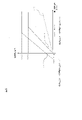
- FIG. 4 is a graph showing the relationship between the upper limit of acceleration set by the control method shown in FIG. 3 and the lateral acceleration deviation
- FIG. 6 is a graph showing the relationship between the acceleration upper limit value set by the operation control method shown in FIG. 5 and the lateral acceleration deviation;
- FIG. 6 is a graph showing the relationship between the acceleration upper limit value set by the operation control method shown in FIG. 5 and the lateral acceleration deviation
- FIG. 1 is a block diagram showing the configuration of an operation control device 100 according to this embodiment.
- the operation control device 100 of this embodiment is also an embodiment for carrying out the operation control method according to the present invention.
- a vehicle operation control device 100 according to the present embodiment includes a sensor 1, a vehicle position detection unit 2, a map database 3, an in-vehicle device 4, a presentation device 5, and an input device 6. , a drive control device 7 and a control device 10 . These devices are connected by, for example, a CAN (Controller Area Network) or other in-vehicle LAN in order to mutually transmit and receive information.
- CAN Controller Area Network
- the sensor 1 includes an acceleration detection section 1a.
- the acceleration detection unit 1a is an acceleration sensor that detects lateral acceleration and longitudinal acceleration of the vehicle.
- the detection result of the acceleration detection unit 1a is output to the control device 10 at predetermined time intervals.
- the sensor 1 includes, for example, a vehicle speed sensor for detecting vehicle speed, a front camera for imaging the front of the vehicle, a rear camera for imaging the rear of the vehicle, and an obstacle in front of the vehicle.
- a touch sensor that detects obstacles behind the vehicle, rear radar that detects obstacles on the left and right sides of the vehicle, side radar that detects whether the driver is holding the steering wheel
- a touch sensor capactance sensor
- an in-vehicle camera that captures an image of the driver, or the like may be provided.
- the own vehicle position detection unit 2 is composed of a GPS unit, a gyro sensor, a vehicle speed sensor, and the like. Specifically, the own vehicle position detection unit 2 detects radio waves transmitted from a plurality of satellite communications by the GPS unit. As a result, the own vehicle position detection unit 2 periodically acquires the position information of the own vehicle. Further, the own vehicle position detection unit 2 detects the current position of the own vehicle (own vehicle position) based on the acquired position information of the own vehicle, the angle change information acquired from the gyro sensor, and the vehicle speed acquired from the vehicle speed sensor. to detect Information indicating the vehicle position detected by the vehicle position detector 2 is output to the control device 10 at predetermined time intervals.
- the map database 3 is a memory that the control device 10 can access.
- the map database 3 stores high-precision digital map information (high-precision map, dynamic map).
- the map information stored in the map database 3 includes three-dimensional high-precision map information including position information of various facilities and specific points.
- the three-dimensional high-precision map information stored in the map database 3 is three-dimensional map information based on information on the shape and height of roads detected when the data acquisition vehicle travels on actual roads.
- Three-dimensional high-precision map information includes curved roads and their curve sizes (e.g., curvature or radius of curvature), identification information of multiple lanes on roads, junctions of roads, junctions, tollgates, and positions of lane reduction. , and information indicating the location of service areas/parking areas.
- the in-vehicle device 4 is various devices mounted on the vehicle.
- the in-vehicle device 4 operates by being operated by the driver.
- the in-vehicle device 4 is, for example, a steering wheel, an accelerator pedal, a brake pedal, a navigation device, a direction indicator, a wiper, a light, a horn, other specific switches, and the like.
- information indicating the details of the operation is output to the control device 10 .
- the presentation device 5 is, for example, a display of a navigation device, a display built into a room mirror, a display built into a meter section, a head-up display projected on the windshield, a speaker of an audio device, or the like.
- the presentation device 5 notifies the driver of various types of information regarding travel of the host vehicle under the control of the control device 10 .
- the input device 6 is, for example, a device such as a button switch that allows manual input by the driver, a touch panel arranged on the display screen, or a microphone that allows input by the driver's voice.
- the drive control device 7 controls the operation of the own vehicle.
- the drive control device 7 uses the autonomous speed control function to control the operation of the drive mechanism for adjusting the acceleration/deceleration and vehicle speed (the operation of the internal combustion engine in the case of an engine vehicle, the operation of the driving motor in the case of an electric vehicle). (including torque distribution between the internal combustion engine and the traction motor in a hybrid vehicle) and brake operation.
- the drive control device 7 performs steering control of the own vehicle by controlling the operation of the steering actuator using the autonomous steering control function. Further, the drive control device 7 executes lane keep control.
- the drive control device 7 detects the lane marker of the lane in which the vehicle is traveling, and adjusts the traveling position (lateral position) of the vehicle in the width direction so that the vehicle travels in the center of the lane in which the vehicle is traveling. to control. Execution of the lane keep control function executed by the drive control device 7 is switched ON/OFF by an operation by the driver or automatically. Further, the drive control device 7 controls the acceleration/deceleration of the own vehicle by controlling the operation of the drive mechanism and the brake operation.
- the control device 10 includes a ROM (Read Only Memory) that stores a program for controlling the running of the vehicle, a CPU (Central Processing Unit) that executes the program stored in the ROM, and an accessible storage device. It consists of functioning RAM (Random Access Memory).
- ROM Read Only Memory
- CPU Central Processing Unit
- RAM Random Access Memory
- the control device 10 executes a program stored in the ROM by the CPU, thereby transmitting control instructions regarding the vehicle speed and steering of the own vehicle to the drive control device 7 based on the autonomous driving control function.
- control device 10 acquires information about the running state of the own vehicle from the sensor 1 .
- the control device 10 acquires image information of the outside of the vehicle captured by the front camera and the rear camera, and detection results by the front radar, the rear radar, and the side radar. Further, the control device 10 acquires vehicle speed information of the host vehicle detected by the vehicle speed sensor. Furthermore, the control device 10 acquires the acceleration/deceleration of the own vehicle from the acceleration detector 1a.
- control device 10 acquires information on the current position of the vehicle from the vehicle position detection device 12 as travel information.
- the control device 10 also acquires from the map database 13 positional information such as curved roads and their curve sizes (for example, curvature or radius of curvature), confluence points, branch points, and the like.
- control device 10 acquires operation information of the vehicle-mounted device 14 by the driver from the vehicle-mounted device 14 .
- the control device 10 also has an acceleration upper limit setting unit 11 .
- the acceleration upper limit value setting unit 11 sets the acceleration upper limit value in controlling the longitudinal acceleration Af of the vehicle V0 based on the lateral acceleration At when the vehicle V0 travels on the curved road C. .
- the control device 10 performs drive control so that the longitudinal acceleration Af of the vehicle does not exceed the acceleration upper limit value set by the acceleration upper limit setting unit 11 when the own vehicle V0 travels on the curved road C.
- the driving of the own vehicle is controlled via the device 7 .
- the control device 10 sets the acceleration upper limit value when the vehicle V0 travels on the curved road C, so that the lateral acceleration (lateral G) becomes excessively large due to rapid acceleration in the longitudinal direction (traveling direction). To prevent the occupant of own vehicle V0 from getting worse in riding comfort.
- the lateral acceleration At increases as the longitudinal acceleration Af of the vehicle V0 increases.
- the control device 10 While the host vehicle V0 is traveling on the curved road C, the control device 10 generates a vehicle speed command mainly based on the curvature or radius of curvature of the curved road C.
- the control device 10 generates a vehicle speed command so that when the vehicle V0 is traveling on the curved road C, the vehicle speed is lower than when the vehicle V0 is traveling on a straight lane. That is, the control device 10 generates a vehicle speed command so that the vehicle V0 decelerates when the vehicle V0 moves from a straight path to a curved path.
- the control device 10 outputs a vehicle speed command to the drive control device 7 .
- the acceleration upper limit value setting unit 11 sets a reference acceleration upper limit value AU0.
- the reference acceleration upper limit value AU0 is indicated by a one-dot chain line graph in FIG.
- the acceleration upper limit setting unit 11 sets the deviation of the lateral acceleration At from the target lateral acceleration Ata ( As the lateral acceleration deviation dAt) increases, the reference acceleration upper limit value AU0 is set higher.
- the control device 10 sets the modified acceleration upper limit value corresponding to the first lateral acceleration to the modified acceleration corresponding to the second lateral acceleration, which is lower than the first lateral acceleration relative to the target lateral acceleration Ata.
- a corrected acceleration upper limit value AU1 is set so as to be higher than the upper limit value.
- the corrected acceleration upper limit value AU1 is set to continuously increase as the relative height of the lateral acceleration At to the target lateral acceleration Ata decreases.
- the corrected acceleration upper limit value AU1 may change stepwise according to the relative height of the lateral acceleration At to the target lateral acceleration Ata.
- the reference acceleration upper limit value AU0 is 0.
- the control device 10 does not accelerate the vehicle V0 in the longitudinal direction.
- the control device 10 prevents the lateral acceleration At of the vehicle V0 from becoming too large due to acceleration in the front-rear direction, and suppresses the occupants of the vehicle V0 from feeling uncomfortable when riding.
- the target lateral acceleration is a reference value indicating the upper limit of the lateral acceleration experimentally determined so that the occupant of the own vehicle V0 does not feel uncomfortable when riding.
- the control device 10 determines whether there is a junction Px in a predetermined section Zx on the downstream side of the curved road C as shown in FIG. determine whether or not
- the merging point Px is a point where the own lane T0 on which the own vehicle V0 is traveling and the other lane T1 join. It should be noted that the control device 10 moves the confluence to the predetermined section Zx on the downstream side of the curved road C when the distance L1 between the downstream end point Pc of the curved road C and the confluence point Px is equal to or less than the distance Lx of the predetermined section Zx. It is determined that Px exists.
- the distance Lx of the predetermined section Zx is a distance that allows the vehicle V0 to reach the target vehicle speed at the junction Px by accelerating before passing the downstream end point Pc of the curved road C.
- distance means the length along the travel locus R0 of the own vehicle V0 (distance traveled by the own vehicle V0).
- step S5 When it is determined in step S2 in FIG. 3 that the confluence point Px does not exist in the predetermined section Zx, the control device 10 advances the process to step S5, and issues a vehicle speed command based on the set reference acceleration upper limit value AU0. Generate. Specifically, in step S5, the vehicle speed of the host vehicle V0 is set according to the curvature of the curved road C, and the longitudinal acceleration Af is set to be equal to or less than the reference acceleration upper limit value AU0. That is, when the confluence point Px does not exist in the predetermined section Zx, the acceleration upper limit value is set to the reference acceleration upper limit value AU0. On the other hand, when it is determined in step S2 that the confluence point Px does not exist in the predetermined section Zx, the control device 10 advances the process to step S3.
- the predetermined distance Ly L1+L2
- the downstream curve section Zd is a section of the curved road C whose distance from the downstream end point Pc is a predetermined downstream curve distance L2.
- the control device 10 controls the vehicle traveling on the curved road C. It is determined that the distance (L1+L0) between the position P0 of the vehicle V0 and the junction Px is less than or equal to the predetermined distance Ly.
- control device 10 controls the predetermined distance Ly and downstream speed so that the vehicle V0 can reach the target vehicle speed at the confluence Px by accelerating the vehicle V0 at the point where the distance to the confluence Px is the predetermined distance Ly.
- step S3 of FIG. 3 when it is determined that the distance (L1+L0) between the position P0 of the own vehicle V0 and the merging point Px is longer than the predetermined distance Ly, the control device 10 advances the process to step S5, A vehicle speed command is generated based on the acceleration upper limit value AU0. That is, when the own vehicle V0 is traveling on the curved road C upstream of the downstream curve section Zd, the acceleration upper limit value is set to the reference acceleration upper limit value AU0. On the other hand, if it is determined in step S3 that the distance (L1+L0) between the position P0 of the host vehicle V0 and the junction Px is equal to or less than the predetermined distance Ly, the control device 10 advances the process to step S4.
- step S4 the control device 10 changes the acceleration upper limit value to a corrected acceleration upper limit value AU1 higher than the reference acceleration upper limit value AU0. That is, as shown in FIG. 2, the control device 10 controls the vehicle V0 that has been traveling on the upstream side of the curved road C from the downstream curved section Zd to enter the downstream curved section Zd of the curved road C. , the acceleration upper limit value is switched from the reference acceleration upper limit value AU0 to the corrected acceleration upper limit value AU1.
- the upper limit value setting unit 11 sets the corrected acceleration upper limit value AU1 higher as the lateral acceleration deviation dAt increases. That is, control device 10 sets corrected acceleration upper limit value AU1 higher as lateral acceleration At of own vehicle V0 is relatively lower than target lateral acceleration Ata in the range of lateral acceleration deviation dAt from 0 to dAt1.
- the rate of change of the corrected acceleration upper limit value AU1 with respect to the lateral acceleration deviation dAt is greater than the rate of change of the reference acceleration upper limit value AU0 with respect to the lateral acceleration deviation dAt.
- the corrected acceleration upper limit value AU1 becomes the acceleration upper limit threshold value AUx1
- the corrected acceleration upper limit value AU1 is constant at the acceleration upper limit threshold value AUx1.
- the control device 10 sets the corrected acceleration upper limit value AU1 to be equal to or less than a predetermined acceleration upper limit threshold value AUx1.
- the acceleration upper limit threshold AUx1 is a value determined experimentally in advance so that the occupant does not feel too uncomfortable due to sudden acceleration of the vehicle V0 in the longitudinal direction.
- the control device 10 changes the acceleration upper limit value to the modified acceleration upper limit value AU1 in step S4 of FIG. 3, it generates a vehicle speed command based on the modified acceleration upper limit value AU1 in step S5. Specifically, in step S5, the vehicle speed of the host vehicle V0 is set according to the curvature of the curved road C, and the longitudinal acceleration Af is set to be equal to or less than the corrected acceleration upper limit value AU1. Further, the control device 10 sets the vehicle speed so that the vehicle speed of the host vehicle V0 reaches the target vehicle speed at the time of merging at the merging point Px.
- the control device 10 of the operation control device 100 can control the own vehicle traveling on the curved road C when the confluence point Px exists in the predetermined section Zx on the downstream side of the curved road C.
- the acceleration upper limit is set to a corrected acceleration upper limit AU1 higher than the reference acceleration upper limit AU0.
- the operation control device 100 loosens the suppression of the acceleration of the vehicle V0 traveling on the curved road C, and the vehicle V0 is more likely to travel in the predetermined section Zx on the downstream side of the curved road C than in the case where the confluence point Px does not exist.
- the operation control device 100 can accelerate the timing of acceleration. Therefore, the operation control device 100 can accelerate the own vehicle V0 early so that the vehicle speed of the own vehicle V0 reaches the target vehicle speed at the time of merging at the merging point PX. Therefore, the operation control device 100 can prevent the own vehicle V0 from losing an opportunity to merge into the other lane T1 due to insufficient speed of the own vehicle V0 at the merging point Px. Also, the occupant of the own vehicle V0 can feel that the own vehicle V0 is accelerating toward the junction PX at a fast pace.
- the control device 10 changes the acceleration upper limit value from the reference acceleration upper limit value AU0 to the corrected acceleration upper limit value AU1.
- the operation control device 100 raises the acceleration upper limit value from the reference acceleration upper limit value AU0 to the corrected acceleration upper limit value AU1 at the timing when the own vehicle V0 traveling on the curved road C approaches the confluence point PX.
- the own vehicle V0 can be accelerated at a fast pace.
- control device 10 sets the corrected acceleration upper limit value AU1 based on the lateral acceleration deviation dAt of the lateral acceleration At with respect to the target lateral acceleration Ata.
- the operation control device 100 sets the corrected acceleration upper limit value AU1 based on the predetermined target lateral acceleration Ata so that the ride comfort of the occupant of the own vehicle V0 traveling on the curved road C does not deteriorate excessively. Can be set.
- the control device 10 determines that the lower the lateral acceleration At of the vehicle V0 relative to the target lateral acceleration Ata, the corrected acceleration upper limit value Set AU1 high. As a result, the control device 10 can set the corrected acceleration upper limit value AU1 high within a range in which the lateral acceleration At can be increased in accordance with the target lateral acceleration Ata, thereby loosening the suppression of the acceleration of the host vehicle V0.
- control device 10 sets the modified acceleration upper limit AU1 to be equal to or less than a predetermined acceleration upper threshold AUx1.
- control device 10 prevents corrected acceleration upper limit value AU1 from becoming too high. That is, the control device 10 can suppress sudden acceleration in the front-rear direction of the vehicle V0 traveling on the curved road C.
- FIG. Note that the control device 10 may set the modified acceleration upper limit value AU1 higher than the acceleration upper limit threshold value AUx1 without setting the acceleration upper limit threshold value AUx1, without being limited to the present embodiment.
- the control device 10 determines that the distance (L1+L0) between the position P0 of the own vehicle V0 and the junction Px is the predetermined distance Ly. Determined as below. As a result, the control device 10 sets the acceleration upper limit value to the corrected acceleration upper limit value AU1 higher than the reference acceleration upper limit value AU0 when the own vehicle V0 is traveling in a section near the end point Pc on the downstream side of the curved road C. can.
- the presentation device 5 of the driving control device 100 presents information indicating the change of the acceleration upper limit value to the occupant of the own vehicle V0. You may
- the own vehicle V0 runs autonomously by the automatic driving function of the control device 10, but the control device 10 is not limited to this, and the driver of the own vehicle V0 manually controls the vehicle speed. Even if it does, the upper limit of acceleration on the curved road C may be set.
- FIGS. 1 to 4 A second embodiment of the operation control method using the operation control device 100 will be described with reference to FIGS.
- the same reference numerals as those shown in FIGS. 1 to 4 indicate the same configuration and processing, and detailed description thereof will be omitted.
- step S3 when it is determined in step S3 that the distance (L1+L0) between the position P0 of the own vehicle V0 and the merging point Px is equal to or less than the predetermined distance Ly, the control device 10 causes the process to proceed to step S11.
- step S11 the control device 10 determines whether or not the lane keep control function of the host vehicle V0 is being executed (whether the lane keep control function is ON or OFF). If the lane keep control function is being executed (the lane keep control function is ON), control device 10 advances the process to step S12. On the other hand, if the lane keep control function is not being executed (the lane keep control function is OFF), control device 10 advances the process to step S13.
- step S12 the control device 10 changes the acceleration upper limit value to a first corrected acceleration upper limit value AU11 higher than the reference acceleration upper limit value AU0.
- the first corrected acceleration upper limit value AU11 is the same value as the corrected acceleration upper limit value AU1 shown in FIG. That is, the first corrected acceleration upper limit value AU11 has the same relationship as the corrected acceleration upper limit value AU1 with respect to the lateral acceleration deviation dAt. Therefore, the detailed description of the first corrected acceleration upper limit value AU11 will be omitted here, citing the contents already described.
- the first modified acceleration upper limit value AU11 is not limited to the same value as the modified acceleration upper limit value AU1 shown in FIG. 4 as long as it is higher than the reference acceleration upper limit value AU0 and lower than the second modified acceleration upper limit value AU12.
- step S13 the control device 10 changes the acceleration upper limit value to a second corrected acceleration upper limit value AU12 higher than the reference acceleration upper limit value AU0 and the first corrected acceleration upper limit value AU11.
- the acceleration upper limit setting unit 11 sets the target lateral acceleration Ata to The second corrected acceleration upper limit value AU12 is set higher as the lateral acceleration At of V0 is relatively lower.
- the control device 10 sets the modified acceleration upper limit value corresponding to the first lateral acceleration to the modified acceleration corresponding to the second lateral acceleration, which is lower than the first lateral acceleration relative to the target lateral acceleration Ata.
- a second corrected acceleration upper limit value AU12 is set to be higher than the upper limit value.
- the second corrected acceleration upper limit value AU12 is set to continuously increase as the relative height of the lateral acceleration At to the target lateral acceleration Ata decreases.
- the second modified acceleration upper limit value AU12 may change stepwise according to the relative height of the lateral acceleration At to the target lateral acceleration Ata. In the graph shown in FIG.
- the lateral acceleration deviation dAt takes a positive value when the lateral acceleration At is lower than the target lateral acceleration Ata, and takes a negative value when the lateral acceleration At is higher than the target lateral acceleration Ata. shall be taken.
- the rate of change of the second corrected acceleration upper limit value AU12 with respect to the lateral acceleration deviation dAt is greater than the rate of change of the first corrected acceleration upper limit value AU11, but is limited to this.
- the change rate of the second corrected acceleration upper limit value AU12 and the change rate of the first corrected acceleration upper limit value AU11 may be the same.
- the second corrected acceleration upper limit AU12 becomes the acceleration upper limit threshold AUx2.
- the upper limit value AU12 is constant at the acceleration upper threshold value AUx2. That is, the control device 10 sets the second corrected acceleration upper limit value AU12 to be equal to or lower than the predetermined acceleration upper limit threshold value AUx2.
- the acceleration upper threshold AUx2 of the second corrected acceleration upper limit AU12 is higher than the acceleration upper threshold AUx1 of the first corrected acceleration upper limit AU11. That is, the control device 10 sets the acceleration upper limit threshold higher when the lane keep control function of the host vehicle V0 is not executed than when the lane keep control function is executed.
- the control device 10 of the operation control device 100 when the lane keep control function of the own vehicle V0 is not being executed, the corrected acceleration upper limit value is higher than when the lane keep control function is being executed.
- Set AU1 high That is, the control device 10 sets the second corrected acceleration upper limit value AU12 when the lane keep control function of the host vehicle V0 is not executed (when it is OFF), and when the lane keep control function is executed (when it is ON). is set higher than the first corrected acceleration upper limit value AU11 when the acceleration is present). Accordingly, when the lane keep control function of the host vehicle V0 is not executed, a relatively higher lateral acceleration At is allowed with respect to the target lateral acceleration Ata than when the lane keep control function is executed.
- control device 10 can advance the acceleration timing of the own vehicle V0 traveling on the curved road C.
- control device 10 sets corrected acceleration upper limit AU1 to a first corrected acceleration lower than second corrected acceleration upper limit AU12.
- the upper limit value AU11 By setting the upper limit value AU11, the lateral behavior of the vehicle V0 can be controlled so that the lateral acceleration At does not exceed the target lateral acceleration Ata.
- control device 10 sets the acceleration upper limit threshold AUx2 when the lane keep control function of the host vehicle V0 is not executed (when it is OFF), and when the lane keep control function is executed (when it is ON). is set higher than the acceleration upper limit threshold AUx1.
- the control device 10 can limit the longitudinal acceleration Af on the curved road C less when the lane keep control function of the host vehicle V0 is not performed than when it is performed. Therefore, the control device 10 can advance the acceleration timing of the own vehicle V0 traveling on the curved road C when the lane keep control function of the own vehicle V0 is not executed.
Landscapes
- Engineering & Computer Science (AREA)
- Automation & Control Theory (AREA)
- Transportation (AREA)
- Mechanical Engineering (AREA)
- Control Of Driving Devices And Active Controlling Of Vehicle (AREA)
- Traffic Control Systems (AREA)
Priority Applications (5)
| Application Number | Priority Date | Filing Date | Title |
|---|---|---|---|
| CN202180004780.5A CN115707333B (zh) | 2021-05-28 | 2021-05-28 | 驾驶控制方法及驾驶控制装置 |
| EP21844609.4A EP4349674B1 (en) | 2021-05-28 | 2021-05-28 | Driving control method and driving control device |
| US17/630,416 US12012104B2 (en) | 2021-05-28 | 2021-05-28 | Driving control method and driving control device |
| PCT/JP2021/020563 WO2022249490A1 (ja) | 2021-05-28 | 2021-05-28 | 運転制御方法及び運転制御装置 |
| JP2022503571A JP7211551B1 (ja) | 2021-05-28 | 2021-05-28 | 運転制御方法及び運転制御装置 |
Applications Claiming Priority (1)
| Application Number | Priority Date | Filing Date | Title |
|---|---|---|---|
| PCT/JP2021/020563 WO2022249490A1 (ja) | 2021-05-28 | 2021-05-28 | 運転制御方法及び運転制御装置 |
Publications (1)
| Publication Number | Publication Date |
|---|---|
| WO2022249490A1 true WO2022249490A1 (ja) | 2022-12-01 |
Family
ID=84229589
Family Applications (1)
| Application Number | Title | Priority Date | Filing Date |
|---|---|---|---|
| PCT/JP2021/020563 Ceased WO2022249490A1 (ja) | 2021-05-28 | 2021-05-28 | 運転制御方法及び運転制御装置 |
Country Status (5)
| Country | Link |
|---|---|
| US (1) | US12012104B2 (https=) |
| EP (1) | EP4349674B1 (https=) |
| JP (1) | JP7211551B1 (https=) |
| CN (1) | CN115707333B (https=) |
| WO (1) | WO2022249490A1 (https=) |
Families Citing this family (3)
| Publication number | Priority date | Publication date | Assignee | Title |
|---|---|---|---|---|
| US11520338B2 (en) * | 2020-02-27 | 2022-12-06 | Uatc, Llc | Systems and methods for vehicle spatial path sampling |
| JP7505448B2 (ja) * | 2021-06-08 | 2024-06-25 | 株式会社アイシン | 運転支援装置 |
| JP7613344B2 (ja) * | 2021-11-17 | 2025-01-15 | トヨタ自動車株式会社 | 先行車選定装置、先行車選定方法及び先行車選定用コンピュータプログラム |
Citations (3)
| Publication number | Priority date | Publication date | Assignee | Title |
|---|---|---|---|---|
| JP2001030797A (ja) * | 1999-07-26 | 2001-02-06 | Mazda Motor Corp | 車両の走行制御装置 |
| WO2019008649A1 (ja) * | 2017-07-03 | 2019-01-10 | 日産自動車株式会社 | 運転支援車両の目標車速生成方法及び目標車速生成装置 |
| JP2019171965A (ja) | 2018-03-27 | 2019-10-10 | 株式会社Subaru | 車両の走行制御装置 |
Family Cites Families (16)
| Publication number | Priority date | Publication date | Assignee | Title |
|---|---|---|---|---|
| JP3413476B2 (ja) * | 1997-07-16 | 2003-06-03 | 国土交通省国土技術政策総合研究所長 | 自動運転車両の自動合流システム |
| JPH1142955A (ja) * | 1997-07-25 | 1999-02-16 | Toyota Motor Corp | 車両走行制御装置 |
| US7092815B2 (en) * | 2003-12-17 | 2006-08-15 | Vrbia, Inc. | Traffic control systems for vehicle spacing to dissipate traffic gridlock |
| JP4639951B2 (ja) * | 2005-05-19 | 2011-02-23 | トヨタ自動車株式会社 | 運転支援装置 |
| JP5251216B2 (ja) * | 2007-07-31 | 2013-07-31 | 日産自動車株式会社 | 車両用走行制御装置および車両用走行制御方法 |
| JP5076852B2 (ja) * | 2007-12-10 | 2012-11-21 | トヨタ自動車株式会社 | 走行制御装置 |
| JP2009262895A (ja) * | 2008-04-30 | 2009-11-12 | Nissan Motor Co Ltd | 車両用走行制御装置 |
| JP5026381B2 (ja) * | 2008-09-25 | 2012-09-12 | 日立オートモティブシステムズ株式会社 | 加減速制御装置 |
| JP6206120B2 (ja) * | 2013-11-21 | 2017-10-04 | 日産自動車株式会社 | 合流支援システム |
| SE1450601A1 (sv) * | 2014-05-21 | 2015-11-22 | Scania Cv Ab | Förfarande och system för anpassning av ett fordons framförande på en vägbana i samband med kurvkörning |
| JP2017001485A (ja) * | 2015-06-09 | 2017-01-05 | トヨタ自動車株式会社 | 車両の運転支援装置 |
| JP6907554B2 (ja) * | 2017-01-24 | 2021-07-21 | スズキ株式会社 | 走行制御装置 |
| JP6814710B2 (ja) * | 2017-08-10 | 2021-01-20 | 日立オートモティブシステムズ株式会社 | 車両運動制御装置及びその方法、並びに、目標軌道生成装置及びその方法 |
| DE102018002335A1 (de) * | 2018-03-21 | 2019-09-26 | Zf Active Safety Gmbh | Steuerungssystem und Steuerungsverfahren zum vorausschauenden Begrenzen einer Fahrzeugbeschleunigung |
| JP2019175097A (ja) * | 2018-03-28 | 2019-10-10 | 株式会社Subaru | 車両の運転支援システム |
| US11561548B2 (en) * | 2020-09-11 | 2023-01-24 | Uatc, Llc | Systems and methods for generating basis paths for autonomous vehicle motion control |
-
2021
- 2021-05-28 EP EP21844609.4A patent/EP4349674B1/en active Active
- 2021-05-28 US US17/630,416 patent/US12012104B2/en active Active
- 2021-05-28 CN CN202180004780.5A patent/CN115707333B/zh active Active
- 2021-05-28 WO PCT/JP2021/020563 patent/WO2022249490A1/ja not_active Ceased
- 2021-05-28 JP JP2022503571A patent/JP7211551B1/ja active Active
Patent Citations (3)
| Publication number | Priority date | Publication date | Assignee | Title |
|---|---|---|---|---|
| JP2001030797A (ja) * | 1999-07-26 | 2001-02-06 | Mazda Motor Corp | 車両の走行制御装置 |
| WO2019008649A1 (ja) * | 2017-07-03 | 2019-01-10 | 日産自動車株式会社 | 運転支援車両の目標車速生成方法及び目標車速生成装置 |
| JP2019171965A (ja) | 2018-03-27 | 2019-10-10 | 株式会社Subaru | 車両の走行制御装置 |
Non-Patent Citations (1)
| Title |
|---|
| See also references of EP4349674A4 |
Also Published As
| Publication number | Publication date |
|---|---|
| CN115707333A (zh) | 2023-02-17 |
| CN115707333B (zh) | 2023-08-22 |
| US12012104B2 (en) | 2024-06-18 |
| US20230382387A1 (en) | 2023-11-30 |
| EP4349674B1 (en) | 2025-08-27 |
| JP7211551B1 (ja) | 2023-01-24 |
| EP4349674A4 (en) | 2024-07-24 |
| JPWO2022249490A1 (https=) | 2022-12-01 |
| EP4349674A1 (en) | 2024-04-10 |
Similar Documents
| Publication | Publication Date | Title |
|---|---|---|
| US12447991B2 (en) | Vehicle lane change control method and vehicle lane change control device | |
| US11180143B2 (en) | Vehicle control device | |
| US10173680B2 (en) | Vehicle speed control device | |
| JP7434866B2 (ja) | 車両の走行制御方法および走行制御装置 | |
| JP7188325B2 (ja) | 運転支援装置 | |
| JP7211551B1 (ja) | 運転制御方法及び運転制御装置 | |
| US20240294188A1 (en) | Vehicle control device | |
| JP7211552B2 (ja) | 車両の走行制御方法及び走行制御装置 | |
| JP7613575B2 (ja) | 運転支援方法及び運転支援装置 | |
| US12097858B2 (en) | Travel control method and travel control device for vehicle | |
| JP7471150B2 (ja) | 走行支援方法、及び、走行支援装置 | |
| JP7524036B2 (ja) | 車両の走行制御方法及び走行制御装置 | |
| JP7788045B2 (ja) | 車両の走行制御方法及び走行制御装置 | |
| JP2022072209A (ja) | 車両の走行制御方法及び走行制御装置 | |
| JP7740504B2 (ja) | 車両制御方法及び車両制御装置 | |
| JP2022072222A (ja) | 車両の走行制御方法及び走行制御装置 | |
| JP7811322B2 (ja) | 車両の走行制御方法及び走行制御装置 | |
| US20260001481A1 (en) | Drive assist apparatus for vehicle | |
| JP7563216B2 (ja) | 車両の走行制御方法及び走行制御装置 | |
| RU2792474C1 (ru) | Способ управления вождением и устройство управления вождением | |
| WO2023054197A1 (ja) | 車両制御装置 | |
| JP2006044468A (ja) | 車両用走行制御装置 | |
| JP2019209931A (ja) | 自動運転システムおよび自動運転プログラム |
Legal Events
| Date | Code | Title | Description |
|---|---|---|---|
| ENP | Entry into the national phase |
Ref document number: 2022503571 Country of ref document: JP Kind code of ref document: A |
|
| WWE | Wipo information: entry into national phase |
Ref document number: 2022102514 Country of ref document: RU |
|
| 121 | Ep: the epo has been informed by wipo that ep was designated in this application |
Ref document number: 21844609 Country of ref document: EP Kind code of ref document: A1 |
|
| WWP | Wipo information: published in national office |
Ref document number: 2022102514 Country of ref document: RU |
|
| NENP | Non-entry into the national phase |
Ref country code: DE |
|
| WWE | Wipo information: entry into national phase |
Ref document number: 2021844609 Country of ref document: EP |
|
| ENP | Entry into the national phase |
Ref document number: 2021844609 Country of ref document: EP Effective date: 20240102 |
|
| WWG | Wipo information: grant in national office |
Ref document number: 2021844609 Country of ref document: EP |
|
| WWW | Wipo information: withdrawn in national office |
Ref document number: 2022102514 Country of ref document: RU |