WO2022208935A1 - 構造体、振動デバイス、体感音響装置、構造体の設計方法、構造体の製造方法、およびプログラム - Google Patents
構造体、振動デバイス、体感音響装置、構造体の設計方法、構造体の製造方法、およびプログラム Download PDFInfo
- Publication number
- WO2022208935A1 WO2022208935A1 PCT/JP2021/034479 JP2021034479W WO2022208935A1 WO 2022208935 A1 WO2022208935 A1 WO 2022208935A1 JP 2021034479 W JP2021034479 W JP 2021034479W WO 2022208935 A1 WO2022208935 A1 WO 2022208935A1
- Authority
- WO
- WIPO (PCT)
- Prior art keywords
- vibrating
- vibration
- support
- housing
- vibrating body
- Prior art date
- Legal status (The legal status is an assumption and is not a legal conclusion. Google has not performed a legal analysis and makes no representation as to the accuracy of the status listed.)
- Ceased
Links
Images







Classifications
-
- B—PERFORMING OPERATIONS; TRANSPORTING
- B06—GENERATING OR TRANSMITTING MECHANICAL VIBRATIONS IN GENERAL
- B06B—METHODS OR APPARATUS FOR GENERATING OR TRANSMITTING MECHANICAL VIBRATIONS OF INFRASONIC, SONIC, OR ULTRASONIC FREQUENCY, e.g. FOR PERFORMING MECHANICAL WORK IN GENERAL
- B06B3/00—Methods or apparatus specially adapted for transmitting mechanical vibrations of infrasonic, sonic, or ultrasonic frequency
- B06B3/02—Methods or apparatus specially adapted for transmitting mechanical vibrations of infrasonic, sonic, or ultrasonic frequency involving a change of amplitude
-
- B—PERFORMING OPERATIONS; TRANSPORTING
- B06—GENERATING OR TRANSMITTING MECHANICAL VIBRATIONS IN GENERAL
- B06B—METHODS OR APPARATUS FOR GENERATING OR TRANSMITTING MECHANICAL VIBRATIONS OF INFRASONIC, SONIC, OR ULTRASONIC FREQUENCY, e.g. FOR PERFORMING MECHANICAL WORK IN GENERAL
- B06B1/00—Methods or apparatus for generating mechanical vibrations of infrasonic, sonic, or ultrasonic frequency
- B06B1/02—Methods or apparatus for generating mechanical vibrations of infrasonic, sonic, or ultrasonic frequency making use of electrical energy
- B06B1/04—Methods or apparatus for generating mechanical vibrations of infrasonic, sonic, or ultrasonic frequency making use of electrical energy operating with electromagnetism
-
- A—HUMAN NECESSITIES
- A61—MEDICAL OR VETERINARY SCIENCE; HYGIENE
- A61H—PHYSICAL THERAPY APPARATUS, e.g. DEVICES FOR LOCATING OR STIMULATING REFLEX POINTS IN THE BODY; ARTIFICIAL RESPIRATION; MASSAGE; BATHING DEVICES FOR SPECIAL THERAPEUTIC OR HYGIENIC PURPOSES OR SPECIFIC PARTS OF THE BODY
- A61H1/00—Apparatus for passive exercising; Vibrating apparatus; Chiropractic devices, e.g. body impacting devices, external devices for briefly extending or aligning unbroken bones
- A61H1/005—Moveable platforms, e.g. vibrating or oscillating platforms for standing, sitting, laying or leaning
-
- A—HUMAN NECESSITIES
- A61—MEDICAL OR VETERINARY SCIENCE; HYGIENE
- A61H—PHYSICAL THERAPY APPARATUS, e.g. DEVICES FOR LOCATING OR STIMULATING REFLEX POINTS IN THE BODY; ARTIFICIAL RESPIRATION; MASSAGE; BATHING DEVICES FOR SPECIAL THERAPEUTIC OR HYGIENIC PURPOSES OR SPECIFIC PARTS OF THE BODY
- A61H23/00—Percussion or vibration massage, e.g. using supersonic vibration; Suction-vibration massage; Massage with moving diaphragms
- A61H23/02—Percussion or vibration massage, e.g. using supersonic vibration; Suction-vibration massage; Massage with moving diaphragms with electric or magnetic drive
- A61H23/0218—Percussion or vibration massage, e.g. using supersonic vibration; Suction-vibration massage; Massage with moving diaphragms with electric or magnetic drive with alternating magnetic fields producing a translating or oscillating movement
- A61H23/0236—Percussion or vibration massage, e.g. using supersonic vibration; Suction-vibration massage; Massage with moving diaphragms with electric or magnetic drive with alternating magnetic fields producing a translating or oscillating movement using sonic waves, e.g. using loudspeakers
-
- G—PHYSICS
- G05—CONTROLLING; REGULATING
- G05D—SYSTEMS FOR CONTROLLING OR REGULATING NON-ELECTRIC VARIABLES
- G05D19/00—Control of mechanical oscillations, e.g. of amplitude, of frequency, of phase
-
- A—HUMAN NECESSITIES
- A61—MEDICAL OR VETERINARY SCIENCE; HYGIENE
- A61H—PHYSICAL THERAPY APPARATUS, e.g. DEVICES FOR LOCATING OR STIMULATING REFLEX POINTS IN THE BODY; ARTIFICIAL RESPIRATION; MASSAGE; BATHING DEVICES FOR SPECIAL THERAPEUTIC OR HYGIENIC PURPOSES OR SPECIFIC PARTS OF THE BODY
- A61H2201/00—Characteristics of apparatus not provided for in the preceding codes
- A61H2201/01—Constructive details
- A61H2201/0119—Support for the device
- A61H2201/0138—Support for the device incorporated in furniture
- A61H2201/0142—Beds
- A61H2201/0146—Mattresses
-
- A—HUMAN NECESSITIES
- A61—MEDICAL OR VETERINARY SCIENCE; HYGIENE
- A61H—PHYSICAL THERAPY APPARATUS, e.g. DEVICES FOR LOCATING OR STIMULATING REFLEX POINTS IN THE BODY; ARTIFICIAL RESPIRATION; MASSAGE; BATHING DEVICES FOR SPECIAL THERAPEUTIC OR HYGIENIC PURPOSES OR SPECIFIC PARTS OF THE BODY
- A61H2201/00—Characteristics of apparatus not provided for in the preceding codes
- A61H2201/01—Constructive details
- A61H2201/0119—Support for the device
- A61H2201/0138—Support for the device incorporated in furniture
- A61H2201/0149—Seat or chair
-
- B—PERFORMING OPERATIONS; TRANSPORTING
- B06—GENERATING OR TRANSMITTING MECHANICAL VIBRATIONS IN GENERAL
- B06B—METHODS OR APPARATUS FOR GENERATING OR TRANSMITTING MECHANICAL VIBRATIONS OF INFRASONIC, SONIC, OR ULTRASONIC FREQUENCY, e.g. FOR PERFORMING MECHANICAL WORK IN GENERAL
- B06B1/00—Methods or apparatus for generating mechanical vibrations of infrasonic, sonic, or ultrasonic frequency
- B06B1/10—Methods or apparatus for generating mechanical vibrations of infrasonic, sonic, or ultrasonic frequency making use of mechanical energy
Definitions
- the present disclosure relates to a structure, a vibration device, a sensory acoustic device, a structure design method, a structure manufacturing method, and a program.
- a bodily sensation device equipped with a vibration device has been known for some time. Vibrating devices are driven, for example, by electromagnets that convert electrical signals into mechanical vibrations. By driving the vibrating device while the vibrating device is in direct or indirect contact with the user's body, the user can feel the sound produced by the vibration of the vibrating device.
- a body-sensory acoustic device configured by embedding a vibrating device inside a chair or a cushion is known (see Patent Document 1).
- Such somatosensory devices may be used to enhance immersion in video and audio content.
- the user sits or leans against the somatosensory device to view the content.
- the user can enjoy a high sense of immersion by experiencing the sound generated by the vibration from the sensory audio device in addition to the image and sound of the content.
- Vibration devices used in bodily-sensory devices are required to generate vibrations of a strength necessary to allow the user to experience sound, and to have rigidity (that is, load resistance) against the load caused by the user's weight and the like. Desired. However, there is a trade-off between these two requirements. In general, if the support portion that supports the vibrating portion of the vibrating device is configured to have high rigidity, the load resistance of the vibrating device is improved, but the amplitude of the vibration of the vibrating portion is limited, making it difficult to increase the vibration strength. .
- a sensory acoustic device equipped with a plurality of vibrating devices
- mutual interference between the vibrating devices may impair the sensory acoustic quality.
- the vibration generated by the vibrating device may propagate to the outside and interfere with (resonate with or cancel out) the vibration of another vibrating device.
- a structure includes a vibrating section that holds a vibrating body, a housing that at least partially accommodates the vibrating section, and a support section that connects the vibrating section and the housing to support the vibrating section.
- the support portion has dynamic rigidity for amplifying transmission of vibration of at least a predetermined frequency among vibrations generated in at least one direction by the vibrating portion while holding the vibrating body, and holds the vibrating body. It is configured to have the static rigidity necessary to support the vibrating portion in the folded state.
- FIG. 1 shows a system including a structure of a first embodiment of the invention
- FIG. FIG. 2 is a diagram showing another example of FIG. 1
- 2 is a diagram showing a vibration model in the system of FIG. 1
- FIG. 4 is a graph showing the frequency characteristics of the vibration transmissibility of the model of FIG. 3
- 3 shows an analysis model of the static stiffness of the support portion of the structure of the first embodiment of the present invention
- BRIEF DESCRIPTION OF THE DRAWINGS It is the perspective view which looked at the structure of the 1st Example of the 1st Embodiment of this invention from diagonally upper front side.
- FIG. 2 is a plan view showing the structure of the first example of the first embodiment of the present invention with its upper flange portion cut away;
- FIG. 1 shows a system including a structure of a first embodiment of the invention
- FIG. 2 is a diagram showing another example of FIG. 1
- 2 is a diagram showing a vibration model in the system of FIG. 1
- FIG. 8 is a perspective view of the structure with the flange portion shown in FIG. 7 being cut, viewed from a direction different from that of FIG. 6 ;
- FIG. 4 is a perspective view showing a state in which a vibrating body is accommodated in a vibrating portion of the structure of the first example of the first embodiment of the present invention;
- 1 is a perspective view showing an example of a structure having anisotropy with respect to stiffness;
- FIG. It is a figure which shows the structure of the 2nd Example of the 1st Embodiment of this invention, the same figure (a) is the top view, The same figure (b) is a front view which shows only the housing
- 3(c) is a cross-sectional view of the supporting portion taken along the line AA. It is a figure which shows the structure of the 3rd Example of the 1st Embodiment of this invention, the same figure (a) is the top view, The same figure (b) is a front view which shows only the housing
- FIG. 10 is a diagram showing vibration directions of a plurality of vibrating devices in a sensory acoustic device according to a second embodiment of the present invention
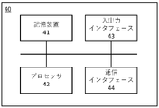
- FIG. 12 is a block diagram showing the configuration of an information processing apparatus according to a third embodiment of the present invention
- FIG. 12 It is a figure which shows the whole flow of the process of the 3rd Embodiment of this invention.
- the inventor of the present invention designed and analyzed various structures, and as a result, isolated the vibration mode in the vibration direction in which the vibration strength is to be increased from the vibration modes in the other directions, and in the vibration direction, While amplifying the vibration of the vibration source, with the idea of solving the above trade-off by giving the rigidity capable of supporting the assumed load, the structure according to the present invention and its design method devised.
- the concept of the present invention is to provide the structure with rigidity capable of supporting the expected load while amplifying the vibration of the vibrating body in the direction in which the vibration intensity is desired to be increased.
- the present invention is capable of amplifying the vibration of the vibration source by softening only the dynamic stiffness in the direction in which the vibration intensity is desired to be increased, and the static stiffness necessary to support the assumed load.
- a rigid structure is provided.
- T direction upward
- B direction downward
- F direction forward
- R direction backward
- SL direction leftward
- SR direction rightward directions
- rotation refers to rotation in one direction (clockwise or counterclockwise) as well as in both directions (clockwise and counterclockwise). can also mean an alternating rotation of .
- the structure of the first embodiment includes a vibration section, a housing, and a support section.
- the vibrating section holds the vibrating body.
- the housing at least partially houses the vibrating section.
- the support section supports the vibrating section by connecting the vibrating section and the housing. The vibrating portion holding the vibrating body vibrates in at least one direction.
- the support portion of the structure of the first embodiment is configured to have dynamic rigidity that amplifies vibration at least at a predetermined frequency among the vibrations generated by the vibrating portion holding the vibrating body.
- the supporting portion is configured to have at least the static rigidity necessary to support the vibrating portion holding the vibrating body.
- the support part secures sufficient rigidity (static rigidity) to stabilize the position and orientation of the vibrating part holding the vibrating body against the assumed load, and also the vibration generated by the vibrating part.
- the vibration intensity can be increased for at least a predetermined frequency of the vibration.
- dynamic stiffness means stiffness represented by the relationship between dynamic force or dynamic moment and resulting dynamic displacement
- static stiffness means static force or static It means the stiffness represented by the relationship between the static moment and the resulting static displacement/deformation.
- FIG. 1 shows a system including the structure of the first embodiment.
- FIG. 2 is a diagram showing another example of FIG.
- the supporting part SPT of the first embodiment supports the vibrating part OS by connecting the vibrating part OS holding the vibrating body and the housing HS.
- the vibrating part OS vibrates at a vibration frequency f.
- the vibrating part OS holding the vibrating body is depicted as if it vibrates due to linear reciprocating motion (hereinafter referred to as “linear reciprocating vibration”).
- linear reciprocating vibration can be oscillated in any direction.
- the vibration unit OS may vibrate by rotational motion (hereinafter referred to as “rotational vibration”) as shown in FIG. (hereinafter referred to as “swing vibration”).
- the vibration of the vibrating section OS may be any combination of the above vibration modes.
- FIG. 3 is a diagram showing a vibration model in the system of FIG.
- FIG. 4 is a graph showing frequency characteristics of the vibration transmissibility of the model of FIG.
- the support part SPT is configured to have a dynamic rigidity that amplifies the vibration at least at the vibration frequency f among the vibrations generated by the vibrating part OS while holding the vibrating body. 3 as a vibration transfer characteristic from the vibrating unit OS to the housing HS. It is determined by the dynamic stiffness kd of the support portion SPT with respect to the vibration direction of the portion OS.
- the ratio F/F0 of the excitation force F transmitted to the housing HS to the excitation force F0 generated by the vibrating part OS while holding the vibrating body is defined as the vibration transmission ratio.
- the model in FIG. 3 exhibits frequency characteristics in which the vibration transmissibility gradually decreases after an excited vibration mode in which the vibration transmissibility increases as the frequency increases.
- the vibration transmissibility of the model in FIG. 3 increases as the frequency becomes higher in the range below fu, and reaches a maximum at fu. where fu is the natural frequency of the model in FIG.
- the vibration transmissibility of the model in FIG. 3 gradually decreases in the frequency range equal to or higher than the natural frequency fu, and crosses zero at ⁇ 2fu. That is, in the model of FIG. 3, the vibration transmissibility is greater than 1 in the range of frequencies less than ⁇ 2fu, that is, the vibration strength can be amplified.
- the natural frequency of the model in Fig. 3 is determined by the mass m and the dynamic stiffness kd.
- the vibration transmissibility in the frequency range increases compared to the vibration transmissibility in the frequency characteristics of the system of the natural frequency fu indicated by the solid line in FIG. Since the mass m is a constant, the natural frequency fu can be lowered by reducing the dynamic stiffness kd. Therefore, from the viewpoint of improving the vibration transmissibility in the low-frequency range, it is preferable that the dynamic stiffness kd of the supporting portion SPT in the vibration direction of the vibrating portion OS holding the vibrating body is as small as possible.
- the support part SPT of the present embodiment is designed to generate vibration at least at a predetermined vibration frequency f, among the frequency components of vibration generated by the vibration part OS holding the vibrating body.
- the dynamic stiffness kd is determined so as to have a natural frequency fu at which the transmissibility is greater than one.
- a system including the supporting portion SPT and the vibrating portion OS having such a dynamic stiffness kd develops an excited vibration mode in which the vibration transmissibility is greater than 1 at the vibration frequency f.
- the support member SPT changes the natural frequency fu of the system including the support member SPT and vibration member OS to the vibration frequency f , and preferably matched to the vibration frequency f.
- the degree of the natural frequency fu of the system including the supporting portion SPT and the vibrating portion OS holding the vibrating body and how to determine the magnitude of the dynamic stiffness kd for that purpose depend on the vibration intensity. It can be appropriately determined according to how much amplification effect is desired at a predetermined vibration frequency f to be increased, that is, how high the vibration transmissibility is desired at the predetermined vibration frequency f.
- the dynamic stiffness kd of the support portion SPT can be derived, for example, by the following procedure.
- One end of the supporting portion SPT is connected to the housing HS, and the other end of the supporting portion SPT is connected to a weight having the same mass m as the vibrating portion OS holding the vibrating body.
- a natural vibration analysis is performed on the system of (1) to identify at least one set of natural frequencies and natural vibration modes.
- the support portion is provided with dynamic rigidity capable of exhibiting a vibration amplifying effect at a predetermined vibration frequency f at which the vibration intensity of the vibrating portion is to be increased, and the vibration direction of the vibrating portion is By increasing the amount of displacement (amplitude) of the supporting portion at , it is possible to increase the vibration intensity of the vibrating portion.
- the vibrating portion is supported in a suspended state with respect to the housing by the supporting portion, transmission of vibration by the vibrating portion to the housing is suppressed, and furthermore, the vibration is suppressed. is suppressed from propagating outside the structure.
- FIG. 5 shows an analysis model of the static stiffness of the supporting portion of the structure of the first embodiment.
- the support part SPT is configured to have static rigidity necessary to support the vibrating part OS while holding the vibrating body. Specifically, as shown in FIG. 5, the support part SPT has a static rigidity ks necessary to support the vibrating part OS against the design load Fl applied to the vibrating part OS.
- Supporting the vibrating part OS can mean, for example, stabilizing the position and orientation of the vibrating part OS even when the design load Fl is applied. Stabilizing the position and orientation can mean suppressing the displacement (including rotational displacement) due to the application of the design load Fl within an allowable range.
- the design load Fl is various loads assumed in the operating environment of the system including the vibrating portion OS and the supporting portion SPT holding the vibrating body.
- the design load Fl can include at least one of the following. Gravity (for example, the weight of the vibrating unit OS holding the vibrating body and the weight of the user acting on the vibrating unit OS) ⁇ inertial force
- the static stiffness ks required to support the vibrating portion OS against the design load Fl is, for example, the amount of displacement of the support portion SPT when the magnitude of the design load Fl is assumed to be the maximum value in the model of FIG. can be defined as the static stiffness that is within the design tolerance.
- the supporting portion SPT supports the vibrating portion OS by giving the supporting portion SPT the static rigidity ks necessary to support the vibrating portion OS in a state where the vibrating body is held against the design load Fl. configured to provide the static strength required for Specifically, when the magnitude of the design load Fl is assumed to be the assumed maximum value in the model of FIG. 5, the continuous distribution of the stress over the support portion SPT is obtained by analysis. Then, the maximum value of the stress distribution (that is, the maximum value of the stress assumed to be locally generated in the support portion SPT due to the design load Fl) is equal to or less than the allowable stress of the material constituting the support portion SPT. Determine SPT shape, location, material, or a combination thereof. Accordingly, even if the assumed maximum design load Fl is applied to the vibrating part OS, the supporting part SPT can stabilize the position and orientation of the vibrating part OS without being damaged.
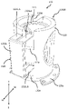
- FIG. 6 is a perspective view of the structure of the first embodiment as seen obliquely from above on the front side.
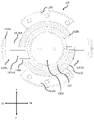
- FIG. 7 is a plan view showing the structure of the first embodiment with its upper flange portion cut away.
- 8 is a perspective view of the structure shown in FIG. 7 with the flange portion cut away, viewed from a direction different from that in FIG. 6.
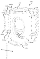
- FIG. 9 is a perspective view showing a state in which the vibrating body is accommodated in the vibrating portion of the structure of the first embodiment.
- FIG. 10 is a perspective view showing an example of a structure having anisotropy in stiffness.
- the supporting part allows the vibrating part to be displaced along the first axis due to the vibration, while the vibrating part It is required to support the vibrating part so that it is not displaced in a direction different from the first axis due to gravity or vibration acting on itself or the vibrating body. Therefore, in such a structure, the dynamic rigidity in the vibration direction of the vibrating body is low enough to amplify the transmission of vibration, and the static rigidity is high enough to support the vibrating part in a stable position and orientation. High is desired.
- the structure 100 of this embodiment is based on the above idea.
- the supporting portion of the structure 100 supports the vibrating portion while holding the vibrating portion 140 (see FIG. 9) that vibrates in the vertical (TB) direction along the first axis. It is explained below.
- the displaceable direction of the vibrating portion 110 and the vibrating direction of the vibrating body held by the vibrating portion 110 are not limited thereto.
- the structure 100 includes a vibrating section 110 holding a vibrating body 140, a housing 120 housing the vibrating section 110, and a state in which the vibrating section 110 is suspended within the housing 120. It has two supporting parts 130SL and 130SR for supporting. The two support portions 130SL and 130SR are arranged differently, but have the same configuration. Therefore, items common to each supporting portion will be described using the reference numeral "130".
- the plane including the front-rear (FR) axis and the left-right (SR-SL) axis substantially coincides with the horizontal plane
- the up-down (TB) axis direction substantially coincides with the vertical direction.
- the vibrating portion 110 has a hollow, substantially cylindrical shape with a bottom portion 110b and an upper opening in the drawing, and a vibrating body 140 is accommodated in the hollow portion of the cylindrical interior as shown in FIG. .
- the vibrating body 140 is fixed to the bottom portion 110b by screwing through a screw hole formed in the bottom portion 110b, for example.
- the inner diameter of the vibrating portion 110 is preferably substantially the same as the outer diameter of the substantially cylindrical vibrating body 140 housed therein. The vibrating portion 110 holding the vibrating body 140 inside in this way can be displaced integrally with the vibrating body 140 .
- the vibrating body 140 is, for example, a linear motor such as a voice coil motor, and the vibrating body 140 held by the vibrating portion 110 linearly reciprocates along the illustrated vertical (TB) axis.
- the vibrating portion 110 linearly reciprocates along the vertical (TB) axis in the drawing in accordance with the vibration generated by the vibrating body 140 .
- Openings 110a are formed at two opposing locations on the side surface of the vibrating portion 110 . These openings 110a allow an operator to reach for attaching or detaching the vibrating body 140 in the vibrating part 110, and also dissipate the heat generated by the vibrating body 140 when the vibrating body 140 is driven. It has a role of dissipating heat to the outside of the vibrating section 110 .
- the housing 120 is configured in a substantially cylindrical shape with at least an upper opening in the drawing, and the whole or at least part of the vibrating section 110 is accommodated in a cylindrical hollow portion around the central axis of the housing 120 .
- the housing 120 accommodates the vibrating section 110 so as to surround the vibrating section 110 entirely.
- Openings 120a are formed at two opposing locations on the side surface of the housing 120 and at positions overlapping the respective openings 110a formed on the side surface of the vibrating unit 110 housed inside. These openings 120a are also accessible to the operator for attaching or detaching the vibrating body 140 to or from the vibrating part 110, and heat generated by the vibrating body 140 when the vibrating body 140 is driven can be dissipated. It has a role of dissipating heat to the outside of the housing 120 .
- a flange portion 120b is formed around the opening in the upper portion of the housing 120 in the figure. In this example, as an example, the flange portion 120b has a shape extending in the horizontal direction of the housing 120 in the drawing. The flange portion 120b plays a role of supporting the load when the user sits or leans on the illustrated upper portion of the housing 120 .
- a mounting flange portion 120c having screw holes is formed around the outer periphery of the lower portion of the housing 120 in the figure.
- mounting flange portions 120c are formed at two locations on the front side and rear side of the housing 120 in the figure.
- the structure 100 can be fixed to the object (not shown) to which the structure 100 is to be attached by, for example, screwing through the screw holes of the mounting flange portion 120c.
- cutouts 120d and 120e are formed in the upper and lower regions of the left and right side surfaces of the housing 120, respectively. These notch portions 120d and 120e allow a support member 132 fixed to the side surface of the vibrating portion 110 among the support portions 130 described later to extend outside the housing 120 through the side wall of the housing 120. and prevent the support 132 from contacting the sidewalls of the housing 120 when the support 132 is displaced.
- the support portion 130 supports the vibrating portion 110 in a suspended state within the housing 120 so that the vibrating portion 110 linearly reciprocates along the first axis (vertical (TB) direction in the illustrated example).
- the vibrating section 110 is concentric with the central axis of the housing 120 in the inner space of the housing 120, and a gap is generated between the outer peripheral surface of the vibrating section 110 and the inner peripheral surface of the housing 120.
- the vibration unit 110 is set at a height such that the bottom surface of the vibration unit 110 does not come into contact with the bottom surface of the housing 120 or the object to which the structure 100 is attached even when the vibration unit 110 is displaced by the maximum amount of displacement that is assumed when vibrating in the vertical direction. position.
- the vibrating section 110 is supported by the supporting section 130 at such an arrangement position.
- a support 132SLA as a first support and a support 131SLA as a second support whose one end (first end) is fixed to the housing 120 and the lower side of the structure 100 shown in the figure vibrate.
- a support 132SLB as a first support having one end (first end) fixed to the portion 110 and a second support having one end (first end) fixed to the housing 120 It includes a support 131SLB as a body and a connecting portion 133SL to which the other ends (second ends) of the supports 131SLA, 132SLA, 131SLB and 132SLB are fixed.
- Support 131SLA and support 132SLA on the upper side in the figure constitute a first set
- support 131SLB and support 132SLB on the lower side in the figure constitute a second set
- the other end portions of the first set of supports 131SLA and 132SLA are fixed to the connection portion 133SL near the illustrated upper end portion of the connection portion 133SL
- the other ends of the second set of supports 131SLB and 132SLB are fixed.
- the end portion is fixed to the connecting portion 133SL in the vicinity of the illustrated lower end portion of the connecting portion 133SL. Therefore, the first set of supports 131SLA and 132SLA and the second set of supports 131SLB and 132SLB are spaced apart from each other along the vertical (TB) axial direction in the figure.
- support 132SLA one end of which is fixed to vibrating section 110 is illustrated left and right (SL-SR).
- the length in the direction is longer than the length in the same direction of the 131SLA, one end of which is fixed to the housing 120 .
- the length in the left-right (SL-SR) direction of the supporting body 132SLB attached is longer than the length in the same direction of 131SLB, one end of which is fixed to the housing 120 .
- the supporting section 130SL configured in this manner allows the relative position of the vibrating section 110 with respect to the housing 120 to be displaced along the vertical (TB) axis by elastic deformation of the respective supporting bodies 131SLA, 132SLA, 131SLB, and 132SLB. It supports the vibrating section 110 .
- the other support portion 130SR also has the same configuration as the support portion 130SL.
- These two support parts 130SL and 130SR are arranged so as to face each other symmetrically about the central axis of the structure 100 (which is also the concentric central axis of the vibrating part 110 and the housing 120).
- FIGS. 6 to 9 show a state in which the vibrating section 110 is positioned at a neutral position with respect to the housing 120 when no vibrating force is acting on the vibrating section 110 .
- an excitation force acting upward in the figure (T direction) acts on the vibrating part 110, and when the vibrating part 110 is displaced upward in the figure with respect to the housing 120, the support fixed to the vibrating part 110 is displaced.
- One end of the body 132SLA and the support 132SLB is also displaced upward in the figure accordingly.
- the support 132SLA and the support 132SLB have one end fixed to the vibrating portion 110 and the other end fixed to the connecting portion 133SL as restraint ends. It is displaced upward in the figure while being bent and deformed within the elastic deformation region so that the end portion fixed to 110 faces the upper side in the figure.
- the connecting portion 133SL to which the other ends of the support 132SLA and the support 132SLB are fixed is also somewhat displaced upward in the drawing.
- the supporting body 131SLB also has one end fixed to the connecting part 133SL and one end fixed to the housing 120 as restraint ends, and the end fixed to the connecting part 133SL is illustrated. It is displaced upward in the figure while being bent and deformed in the elastic deformation region so as to face upward.
- each part of the part 133SL is displaced or deformed in the direction opposite to the above. Although description is omitted, each part of the other support part 130SR also operates in the same manner as each part of the support part 130SL.
- the vibrating portion 110 supported by the supporting portions 130SL and 130SR linearly vibrates reciprocatingly in the vertical (TB) direction in the figure by the vibrating force of the vibrating body 140 as described above.
- the support section 130 is vibrated with respect to the housing 120 by elastic deformation of the illustrated upper and lower supports 132SLA and 132SLB as first supports and the illustrated upper and lower supports 131SLA and 131SLB as second supports. support the vibrating portion 110 so as to be displaceable along the first axis (vertical (TB) axis direction in the drawing).
- the weight of the vibrating body 140 makes the vibrating part 110 slightly larger than when the vibrating body 140 is not housed in the vibrating part 110. Displaced downward in the drawing. Furthermore, when the vibrating body 140 is accommodated in the vibrating section 110 , the illustrated upper portion of the vibrating body 140 slightly protrudes outside the housing 120 from the upper surface of the flange portion 120 b of the upper portion of the housing 120 . Therefore, when the user sits or leans against the illustrated upper portion of the housing 120, the illustrated upper surface of the vibrating body 140 vibrates until it reaches substantially the same height as the upper surface of the upper flange portion 120b of the housing 120.
- the portion 110 is further pushed downward in the drawing, and the vibrating portion 110 is held by the support portions 130SL and 130SR with that position as the neutral position. At this time, the load of the user's body is supported by the flange portion 120b of the housing 120, and the upper upper surface of the vibrating body 140 pushed down together with the vibrating portion 110 comes into contact with the user's body.
- the support portion 130 is configured to generate at least a predetermined vibration frequency among the linear reciprocating vibrations generated along the vertical (TB) axis by the vibrating portion 110 holding the vibrating body 140, in other words, the predetermined vibration. It is configured to have a dynamic stiffness that amplifies vibrations in a frequency band that includes frequencies.
- the dynamic rigidity of the support section 130 is a load that is assumed to be applied to the support section 130 via the vibration section 110 (for example, a load due to the weight of the vibration section 110 holding the vibration body 140 or a load applied to the structure 100). It can be determined in consideration of the load acting on the vibrating section 110 from the body of the user sitting or leaning.
- the vibrating section 110 can generate vibrations of different frequencies according to the speed of the linear reciprocating vibration generated by the vibrating body 140 .
- the support portion 130 makes it possible to amplify vibration in a frequency band including a predetermined frequency for which higher vibration intensity is desired to be achieved.
- the support portion 130 is configured to have static rigidity necessary to support the vibrating portion 110 . That is, the support portion 130 ensures sufficient rigidity (static rigidity) to stabilize the position and orientation of the vibrating portion 110 against an assumed load, and at least the linear reciprocating vibration generated by the vibrating portion 110 A high vibration intensity can be realized with respect to the predetermined vibration frequency.
- the support portion 130 resists the force applied along the vibration direction of the vibrating portion 110 holding the vibrating body 140 (that is, the force applied along the vertical (TB) axis). It is designed to have low dynamic stiffness and static stiffness against the design load.
- the support part 130 can satisfy both the constraint on dynamic stiffness and the constraint on static stiffness by including, for example, a structure having anisotropy in terms of stiffness.
- the support portion 130 has a rigidity against a force applied along a direction different from the rigidity against a force applied along the vibration direction of the vibrating portion 110 holding the vibrating body 140 . is configured to be high.
- Stiffness against force applied along another direction is, for example, all or at least one of the following: ⁇ Stiffness against moment around vertical (TB) axis ⁇ Stiffness against force applied along front-back (FR) axis ⁇ Stiffness against moment around front-back (FR) axis ⁇ Side-left (SL-SR) Stiffness against force applied along the axis / Stiffness against moment around the left-right (SL-SR) axis
- the beam BM shown in FIG. 10 is an example of a structure having anisotropy in terms of rigidity, and corresponds to each support 131SLA, 132SLA, 131SLB, 132SLB in this embodiment.
- the beam BM is such that the dimension a in the vibration direction (that is, the vertical (TB) axis) of the vibrating portion 110 holding the vibrating body 140 is equal to the dimension b of the front-rear (FR) axis and the lateral axis (SL- SR) is small compared to the axis dimension l.
- the stiffness when a force is applied along the vertical (TB) axis to the right end (SR end) of the beam BM while the left end (SL end) of the beam BM is fixed is K b1 ⁇ Ea 3 b/l 3 expressed.
- E Young's modulus.
- the stiffness is K b2 ⁇ Eab 3 /l 3 is. That is, K b2 /K b1 ⁇ b 2 /a 2 .
- the vertical (TB) axis By making the dimension a of the vertical (TB) axis smaller than the dimension b of the front-rear (FR) axis and the dimension l of the lateral axis (SL-SR axis), the vertical (TB) ) the stiffness for forces applied along the axis can be lower than the stiffness for forces applied along other directions.
- Structures with undulating shapes in the vertical (TB) direction also have a stiffness to forces applied along the vertical (TB) axis that is equal to the stiffness to forces applied along the other directions. low compared to
- each support for example, the support 131SLA, the support 131SLB, the support 132SLA, and the support 132SLB
- the support section 130 is moved in the direction along the first axis (that is, the vertical (TB) direction) is smaller than the dimension in the direction perpendicular to the first axis (the front-rear (FR) direction or the left-right (SL-SR) direction).
- the dynamic stiffness in the direction along the first axis of can be reduced.
- the supports 131 and 132 of each support 130 are configured to have the above-described rigidity characteristics, and the two supports 130SL and 130SR are the central axes of the structure 100 (the vibrating section 110 and the housing). ), which is also the concentric center axis of the body 120), the vibrating section 110 can be displaced in the vertical (TB) direction in the drawing with respect to the housing 120. is supported by the support portion 130 so as not to be substantially displaced in other directions.
- each of the supports 131SLA, 132SLA, 131SLB, and 132SLB of the support section 130 has a relatively low dynamic rigidity in the vertical (TB) direction of the drawing as described above.
- the load due to the weight of the vibrating section 110 supporting the vibrating body 140, and the vibration when the vibrating section 110 supporting the vibrating body 140 as described above is pushed downward (B) in the figure by the user's body. It has static stiffness capable of supporting at least the loads applied to the portion 110 .
- the connecting portion (for example, connecting portion 133SL) included in the support portion 130 is separated from the housing 120 in a direction orthogonal to the vibration direction (that is, the vertical (TB) direction) of the vibrating portion 110 holding the vibrating body 140.
- TB vertical
- each support (for example, support 131SLA, support 131SLB, support 132SLA, and support 132SLB) included in the support section 130 looks like a housing when viewed from above (T direction). It extends radially outward from the outer peripheral surface of 120 .
- the vertical (TB) relative to the dimension along the vertical (TB) axis of each support increases. Since the dimension ratio in the direction perpendicular to the axis (left-right (SL-SR) direction) increases, the dynamic rigidity of the support portion 130 in the vibration direction (up-down (TB) direction in the figure) can be made lower.
- the dimensions of each part, including the length of each support are determined in consideration of the size of the structure 100 and the weight of the vibrating body 140, etc. can be appropriately set so that the can be amplified.
- the support portion 130 When the vibrating section 110 holding the vibrating body 140 is in a non-vibrating state, no vibrating force is applied to the support section 130 .
- the support portion 130 is subjected to the above-described load (for example, the weight of the vibrating portion 110 holding the vibrating body 140, or the weight of the structure 100).
- a load acting on the vibrating section 110 by the body of the user sitting or leaning can be applied.
- the supporting portion 130 has static rigidity such that the amount of displacement of the supporting portion 130 is within a design allowable range with respect to the direction in which the design load is applied. Therefore, when the vibrating portion 110 is in the non-vibrating state, the deformation of each support of the support portion 130 remains within the allowable range, and the support portion 130 is in the neutral position after being displaced by the application of the load. To position.
- the supporting part 130 is also subjected to a load along the upward direction in the drawing (T direction). A vibration force is applied.
- the vibrating portion 110 holding the vibrating body 140 is displaced downward in the drawing (direction B)
- an excitation force along the downward direction in the drawing is also applied to the supporting portion 130 .
- the support part 130 has a dynamic rigidity that amplifies at least the vibration of the predetermined frequency among the linear reciprocating vibrations in the vertical (TB) direction in the figure generated by the vibrating part 110 holding the vibrating body 140. It is configured. As a result, at least at the predetermined vibration frequency of the vibrating portion 110, the vibration intensity of the linear reciprocating vibration of the vibrating portion 110 in the vertical (TB) direction in the drawing can be increased.
- the vibrating device configured by the structure 100 of the present embodiment in which the vibrating body 140 is held by the vibrating part 110, the upper surface of the vibrating body 140 is in contact with the user's body.
- the vibrating body 140 is linearly reciprocated in the vertical (TB) direction in the figure, the vibrating part 110 holding it starts reciprocating linear vibration in the same direction, and eventually the vibration frequency reaches the predetermined frequency.
- the to-and-fro linear vibration in the -B) direction is amplified.
- the upper upper surface of the vibrating body 140 held by the vibrating section 110 is displaced in the (T) direction in the drawing, the upper upper surface of the vibrating body 140 contacts the user's body more strongly. In the frequency domain, the acoustic effect of the vibrating device can be felt more strongly. At this time, the user will feel the vibration of the body in addition to the sound and image of the audio/visual content (movie, music live video, etc.) being viewed, so that the user can get a stronger sense of immersion in the content. can be done.
- the vibrating section 110 is supported in a suspended state by the support section 130 so as not to contact the inner wall surface, bottom surface, or the like of the housing 120.
- This suspended state is maintained even while the vibrating portion 110 reciprocating linearly vibrates in the vertical (TB) direction of the drawing.
- the vibration caused by the vibrating section 110 is separated from the housing 120 .
- the vibrating section 110 linearly vibrates back and forth in the illustrated vertical (TB) direction the vibrating section 110 and the vibrating body 140 held by it may come into contact with the inner wall surface, the bottom surface, or the like of the housing 120.
- vibration transmitted from the housing 120 to the outside thereof can be suppressed.
- the vibration from one vibrating device is transmitted to another vibrating device and interferes with the vibration of the other vibrating device. It can be suppressed, and the user can perceive the vibration by the individual vibrating device with higher resolution.
- the vibrating device including the structure 100 and the vibrating body 140 of the present embodiment can displace the vibrating part 110 supported by the supporting part 130 in the reciprocating linear vibration direction of the vibrating part 140 held by the vibrating part 110 .
- direction coincides with the vertical (TB) direction in the drawing, and the vibrating portion 110 is not substantially displaced in other directions. Therefore, most of the vibrational energy of the vibrating body 140 is used to linearly vibrate the vibrating portion 110 back and forth in the vertical (TB) direction in the drawing.
- the vibrating section 110 is linearly reciprocated in the vertical (TB) direction of the drawing, the vibrating section 110 sequentially generates secondary, tertiary, .
- the vibrating portion 110 may vibrate in directions other than the illustrated vertical (TB) direction.
- the vibrating section 110 is configured so that there is substantially no displacement in directions other than the illustrated vertical (TB) direction. 110 can be suppressed from being displaced in the vibration direction. Therefore, even if the vibrating section 110 vibrates in a certain vibration mode in a direction other than the illustrated vertical (TB) direction, the outer peripheral surface of the vibrating section 110 may contact the inner peripheral surface of the housing 120, for example. can be prevented.
- the support member 131SLA of the support portion 130 in order to increase the vibration intensity of the reciprocating linear vibration of the vibrating portion 110 in the vertical (TB) direction of the drawing at a lower frequency, the support member 131SLA of the support portion 130, The shape and dimensions of each support are designed so that the dynamic stiffness kd in the vertical (TB) direction of the drawing by the entirety of 132SLA, 131SLB, and 132SLB is lower.
- the natural frequency fu of the vibration of the system composed of the vibrating portion 110 holding the vibrating body 140 and the supporting portion 130 in the vertical (TB) direction in the drawing shifts to a lower frequency region, It becomes possible to increase the vibration intensity in the frequency domain.
- the illustrated vertical (T-) direction of the vibrating section 110 when increasing the vibration intensity of the reciprocating linear vibration in the illustrated vertical (TB) direction of the vibrating section 110 at a higher frequency, the illustrated vertical (T- The shape and dimensions of each support are designed so that the dynamic stiffness kd in the B) direction is higher. As a result, the natural frequency fu of the vibration in the vertical (TB) direction in the drawing of the system composed of the vibrating portion 110 holding the vibrating body 140 and the support portion 130 shifts to a higher frequency region, It becomes possible to increase the vibration intensity in the frequency domain.
- the structure 100 of the first embodiment includes the support section 130 .
- the supporting section 130 performs vibration of at least a predetermined vibration frequency (vibration in a frequency band including the predetermined vibration frequency).
- the predetermined vibration frequency is, for example, a frequency at which it is desired to amplify the vibration of the vibrating section 110 to obtain a higher vibration strength.
- the support section 130 is configured to have static rigidity necessary to support the vibrating section 110 against an assumed load in the direction in which the designed external force is applied.
- the vibrating portion 110 is supported so that the position and orientation of the vibrating portion 110 are stabilized against the load within the assumed range at the time of design, and at least the linear reciprocating vibration generated by the vibrating portion 110
- the vibration of the predetermined frequency can be amplified.
- this structure 100 it is possible to satisfy the load resistance and vibration strength required of a vibrating device.
- the direction in which the vibrating section 110 can be displaced (vibrated) matches the vibrating direction of the vibrating body 140 held by the vibrating section 110, and the vibrating section 110 is positioned relative to the housing 120. Since it is internally supported by the support portion 130 in a suspended state, it is possible to suppress the occurrence of vibration in the direction of vibration by the vibrating portion 110 and vibration in a direction different from that, and such vibration can be suppressed. can be suppressed from propagating to the outside of the structure 100 .
- the vibrating section 110 holding the vibrating body 140 generates a linear reciprocating vibration along a vertical (TB) axis in the figure, which substantially coincides with the vertical direction.
- TB vertical
- the weight of vibrating section 110 holding 140, the excitation force (inertial force) thereof, and the load from the user's body are applied to vibrating section 110 .
- the support portion 130 is configured to have dynamic rigidity that amplifies at least the vibration of the vibration portion 110 at the predetermined vibration frequency in the vertical (TB) direction, which is the vibration direction of the vibration portion 110.
- the static rigidity required to support the vibrating portion 110 is provided.
- the vibration direction of the vibrating portion 110 supported by the support portion 130 and the direction in which the design external force is applied to the support portion 130 are not limited to this. Moreover, the vibration direction of the vibrating portion 110 supported by the support portion 130 is not limited to one direction.
- the support portion 130 may be configured to have a dynamic stiffness that amplifies vibration at a predetermined vibration frequency in each vibration direction.
- the structure 100 includes two supporting portions 130SL and 130SR arranged symmetrically to face each other with respect to its central axis. is not limited to this, and may be configured to include any number of support portions 130, for example, three or more. At this time, it is preferable that the support portions 130 are arranged at regular intervals around the central axis of the structure 100 . Note that even when the structure 100 includes only one support portion 130, the vibrating body 140 and the vibrating portion 110 come into contact with the inner surface of the housing 120 when the vibrating portion 110 holding the vibrating body 140 vibrates.
- the structure 100 may be configured with only one support 130 under certain conditions where there is no need to do so.
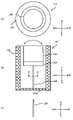
- FIG. 11A and 11B are diagrams showing the structure of the second example of the first embodiment of the present invention, FIG. 11A is a plan view thereof, and FIG. , and FIG. 1(c) is a cross-sectional view of the supporting portion taken along the line AA.
- the structure 200 includes a vibrating portion 210 holding a vibrating body 240, a supporting portion 230 supporting the vibrating portion 210, and a vibrating portion holding the vibrating body 240. 210 and a housing 220 that accommodates the support 230 .
- the vibrating portion 210 has a disk-like shape as an example, and the vibrating body 240 can be held on the upper surface of the drawing.
- the vibrating body 240 can be fixed to the vibrating portion 210 by screwing (not shown), for example.
- the vibrating portion 210 holding the vibrating body 240 can be displaced integrally with the vibrating body 240 .
- the vibrating portion 210 is supported by the support portion 230 in a state in which the lower surface in the figure is fixed to the upper portion in the figure of the support portion 230 .
- the vibrating body 240 has, for example, a substantially cylindrical shape having the same outer diameter as the vibrating portion 210, the shape of the vibrating body 240 is not limited to this.
- the support portion 230 has a cross-shaped cross section along line AA in FIG. 11(b) as shown in FIG. 11(c). ) along the axis. More specifically, the support portion 230 is formed in a shape in which two plate-like members are perpendicular to each other at their central axes. The illustrated upper portion of the support portion 230 is fixed to the vibrating portion 210 as described above, and the illustrated lower portion of the support portion 230 is fixed to the bottom surface 220 a of the housing 220 .
- the housing 220 is configured in a substantially cylindrical shape with an upper opening in the drawing. contain at least part of In the example shown in FIG. 11 and the like, the housing 220 accommodates the vibrating section 210 holding the vibrating body 240 and the supporting section 230 so as to surround the entire circumference thereof.
- the vibrating portion 210 and the support portion 230 holding the vibrating body 240 are concentric with the central axis of the housing 220 in the inner space of the housing 220 and between the outer peripheral surface thereof and the inner peripheral surface of the housing 220. are arranged so that there is a gap between them.
- a flange may be formed around the opening at the top of the housing 220 as shown.
- the vibrating body 240 is, for example, a rotating vibrator capable of rotating and vibrating alternately clockwise and counterclockwise. As indicated by the arrow in (a), the vibrating portion 210 rotates and vibrates alternately clockwise and counterclockwise, and the vibrating portion 210 also rotates and vibrates in the same direction integrally with the vibrating body 240 .
- the upper upper surface of the vibrating body 240 held by the vibrating section 210 is substantially at the same height as the opening surface of the upper portion of the housing 220 in the drawing. Therefore, when the user sits or leans against the illustrated upper portion of the housing 220, the illustrated upper upper surface of the vibrating body 240 may come into contact with the user's body.
- the support portion 230 is configured to generate vibration of at least a predetermined vibration frequency (a frequency band including the predetermined vibration frequency) among the rotational vibrations generated by the vibration portion 210 holding the vibration body 240 about the vertical (TB) axis in the drawing. (vibration at the ).
- the dynamic rigidity of the support section 230 is a load that is assumed to be applied to the support section 230 via the vibration section 210 (for example, a load due to the weight of the vibration section 210 holding the vibration body 240 or a load applied to the structure 200). It can be determined in consideration of the load acting on the vibrating section 210 via the vibrating body 240 due to the body of the user sitting or leaning.
- the vibrating section 210 can generate vibrations of different frequencies according to the rotational vibration speed generated by the vibrating body 240 .
- the support portion 230 makes it possible to amplify vibration in a frequency band including a predetermined frequency for achieving higher vibration strength among those frequencies.
- the support portion 230 is configured to have static rigidity necessary to support the vibrating portion 210 .
- the support portion 230 secures sufficient rigidity (static rigidity) to stabilize the position and orientation of the vibrating portion 210 against an assumed load, and at least the above-described rotational vibration generated by the vibrating portion 210 is ensured.
- a high vibration intensity can be achieved for a given vibration frequency.
- the support portion 230 in this embodiment applies a force along the vibration direction of the vibrating portion 210 holding the vibrating body 240 (that is, a force applied around the vertical (TB) axis in the drawing). It is configured so that it has low dynamic stiffness against the force applied to it, but static stiffness against the design load is obtained.
- the support part 230 can satisfy both the dynamic stiffness constraint and the static stiffness constraint by including, for example, a structure having anisotropic stiffness.
- the support part 230 has the following characteristics due to its geometric shape having a cross section. ⁇ The dynamic rigidity against the rotational moment around the vertical (TB) axis in the figure is low, and torsional deformation in that direction is likely to occur. ⁇ High static rigidity against compression and tension in the vertical (TB) axial direction in the drawing, and substantial deformation in that direction is unlikely to occur. ⁇ High static rigidity against a bending moment in a direction orthogonal to the illustrated vertical (TB) axis direction, and substantial bending deformation in that direction is unlikely to occur.
- each part (height, length and thickness of the cross section, etc.) of the support part 230 are determined in consideration of the size of the structure 200, the weight of the vibrating body 240, etc. It can be appropriately set so that the vibration of 210 can be amplified.
- the supporting part 230 When the user sits or leans against the illustrated upper portion of the structure 200 of the present embodiment in which the vibrating body 240 is held by the vibrating part 210, the supporting part 230 is applied with a design load (for example, the vibrating body 240 is held). A load acting on the vibration part 210 due to the weight of the vibration part 210 when the user sits or leans against the structure 200 may be applied to the vibration part 210 .
- the supporting portion 230 is configured as described above with respect to the application direction of such a design load (the illustrated vertical (TB) axis direction and the direction perpendicular thereto (the illustrated vertical (TB) axis direction)). It has high static stiffness. Therefore, the support portion 230 can support such a designed load, and substantially no displacement due to such a designed load occurs.
- the supporting part 230 When the vibrating body 240 held by the vibrating part 210 enters a vibrating state and the vibrating part 210 holding the vibrating body 240 rotates in one direction around the illustrated vertical (TB) axis, the supporting part 230 also vibrates in the same direction. An excitation force is applied in the direction. On the other hand, when the vibrating portion 210 holding the vibrating body 240 rotates in the other direction around the illustrated vertical (TB) axis, the excitation force is applied to the supporting portion 230 in the same other direction as well.
- the support part 230 has a dynamic rigidity that amplifies at least the vibration of the predetermined frequency among the rotational vibrations about the vertical (TB) axis in the figure generated by the vibration part 210 holding the vibration body 240. It is configured. Thereby, at least at the predetermined vibration frequency of the vibrating portion 210, the vibration intensity of the rotational vibration of the vibrating portion 210 about the vertical (TB) axis in the figure can be increased.
- the vibrating device configured by the structure 200 of the present embodiment in which the vibrating body 240 is held by the vibrating part 210, the upper surface of the vibrating body 240 is in contact with the user's body.
- the vibrating body 240 is rotationally vibrated around the vertical (TB) axis in the figure, the vibrating part 210 holding it starts to rotationally vibrate in the same direction, and when the vibration frequency eventually reaches the predetermined frequency,
- the system including the vibration part 210 holding the vibration body 240 and the support part 230 resonates with the natural frequency of the vibration about the vertical (TB) axis in the drawing, and the vibration part 210 holding the vibration body 240 resonates at the vertical (T -B) Rotational oscillations about the axis are amplified.
- the vibrating body 240 held by the vibrating part 210 is rotationally displaced, the user's body part with which the upper surface of the vibrating body 240 is in contact is stimulated by alternately twisting clockwise and counterclockwise. is given to the user, the user can feel the acoustic effect of the vibrating device more strongly in the frequency range. At this time, the user will feel the vibration of the body in addition to the sound and image of the audio/visual content (movie, music live video, etc.) being viewed, so that the user can get a stronger sense of immersion in the content. can be done.
- the vibrating device including the structure 200 and the vibrating body 240 of the present embodiment is configured so that the vibration direction of the rotational vibration of the vibrating body 240 held by the vibrating section 210 and the displacement of the vibrating section 210 supported by the supporting section 230 are controlled.
- the direction of rotation coincides with the direction of rotation about the vertical (TB) axis in the drawing, and the vibrating portion 210 is not substantially displaced in other directions. Therefore, most of the vibrational energy of the vibrating body 240 is used to rotationally vibrate the vibrating section 210 about the vertical (TB) axis in the drawing.
- the vibrating portion 210 is rotationally vibrated around the vertical (TB) axis in the drawing, secondary, tertiary, .
- the vibrating section 210 may vibrate in directions other than the direction of rotation about the illustrated vertical (TB) axis. 200 is configured so that the vibrating portion 210 is substantially not displaced in directions other than the rotation direction about the illustrated vertical (TB) axis. It is possible to suppress displacement of the vibrating portion 210 in the direction of vibration caused by vibrations that may occur in directions other than the direction of rotation. Therefore, even if the vibrating section 210 vibrates in a certain vibration mode in a direction other than the direction of rotation about the vertical (TB) axis in the drawing, for example, the outer peripheral surfaces of the vibrating section 210 and the vibrating body 240 held by the vibrating section 210 may Contact with the inner peripheral surface of the body 220 can be prevented.
- the vibrating portion 210 is prevented from being displaced in a direction other than the direction of rotation about the vertical (TB) axis in the figure due to vibrations that may occur in the directions other than the direction of rotation. Therefore, it is possible to prevent the vibrating device from vibrating due to displacement in a direction other than the rotational direction about the illustrated vertical (TB) axis, and the vibration from propagating to the outside of the vibrating device. .
- the vibration from one vibrating device is transmitted to another vibrating device and interferes with the vibration of the other vibrating device. It can be suppressed, and the user can perceive the vibration by the individual vibrating device with higher resolution.
- FIG. 12A and 12B are views showing the structure of the third example of the first embodiment of the present invention
- FIG. 12A is a plan view thereof
- FIG. 1(c) is a cross-sectional view of the supporting portion taken along the line BB.
- a structure 250 according to the third embodiment includes a vibrating portion 260 that holds a vibrating body 290 and a vibrating portion 260, similar to the structure 200 according to the second embodiment (see FIG. 260 , and a housing 270 that houses the vibrating section 260 and the supporting section 280 while holding the vibrating body 290 .
- the vibrating body 290 used in this embodiment is, for example, a vibrating body capable of linear reciprocating vibration, and as an example thereof, a linear motor such as a voice coil motor can be used.
- the vibrating body 290 is held by the supporting portion 280 so that the direction of the linear reciprocating vibration coincides with the horizontal (SL-SR) direction in the drawing.
- the vibrating body 290 may be a rotary vibrator capable of rotating and oscillating alternately clockwise and counterclockwise, like the vibrating body 240 of the second embodiment.
- the vibrating body 290 is held by the supporting portion 280 so that its central axis of rotation is orthogonal to the horizontal (SL-SR) direction in the figure.
- the support portion 280 in the structure 250 of the present embodiment has a plate-like shape whose cross section along line BB in FIG. have.
- the illustrated upper portion of the support portion 280 is fixed to the vibrating portion 260 as described above, and the illustrated lower portion of the support portion 280 is fixed to the bottom surface 270 a of the housing 270 .
- the support portion 280 supports at least vibration of a predetermined vibration frequency (vibration in a frequency band including the predetermined vibration frequency) among the vibrations generated in the horizontal (SL-SR) direction in the figure by the vibration portion 260 holding the vibrator 290. ) is configured to have a dynamic stiffness that amplifies the
- the dynamic rigidity of the support section 280 is determined by the load that is assumed to be applied to the support section 280 via the vibration section 260 (for example, the load due to the weight of the vibration section 260 holding the vibration body 290 and the load applied to the structure 250). It can be determined in consideration of the load acting on the vibrating section 260 via the vibrating body 290 due to the body of the user sitting or leaning.
- the vibrating section 260 can generate vibrations of different frequencies according to the speed of vibration generated by the vibrating body 290 .
- the support portion 280 makes it possible to amplify vibration in a frequency band including a predetermined frequency for achieving higher vibration strength among those frequencies.
- the support portion 280 is configured to have static rigidity necessary to support the vibrating portion 260 . That is, the support portion 280 ensures sufficient rigidity (static rigidity) to stabilize the position and orientation of the vibrating portion 260 against an assumed load, and at least the above-mentioned predetermined amount of vibration generated by the vibrating portion 260 A high vibration intensity can be realized with respect to the vibration frequency of
- the support portion 280 in this embodiment applies a force along the vibration direction of the vibrating portion 260 holding the vibrating body 290 (when the vibrating body 290 is a vibrating body capable of linear reciprocating vibration).
- It is configured to provide static stiffness against load.
- the support part 280 can satisfy both the constraint on dynamic stiffness and the constraint on static stiffness, for example, by including a structure having anisotropy in terms of stiffness.
- the support part 280 has the following characteristics due to its planar geometry. ⁇ The dynamic rigidity against the bending moment in the illustrated left-right (SL-SR) direction and about the illustrated front-rear (FR) axis is low, and bending deformation in that direction is likely to occur. ⁇ High static rigidity against compression and tension in the vertical (TB) axial direction in the drawing, and substantial deformation in that direction is unlikely to occur. ⁇ High static rigidity against a bending moment in a direction perpendicular to the illustrated left-right (SL-SR) direction (the illustrated front-rear (FR) direction), and substantial bending deformation in that direction is unlikely to occur.
- the support portion 280 When the vibrating body 290 is a vibrating body capable of linear reciprocating vibration, as described above, the support portion 280 has low dynamic rigidity against a bending moment in the left and right (SL-SR) directions of the drawing, and bending deformation in that direction occurs.
- the vibrating body 290 since the vibrating body 290 is held by the supporting portion 280 so that the direction of linear reciprocating vibration is aligned with the horizontal (SL-SR) direction in the figure, the vibrating body 290 generates linear reciprocating vibration.
- the support portion 280 alternately bends in the left and right (SL-SR) directions in the drawing with the lower end portion fixed to the bottom surface 270a of the housing 270 as a fixed end and the upper end portion fixed to the vibration portion 260 as a free end.
- the supporting portion 280 and the vibrating body 290 held by it alternately oscillate in the left and right (SL-SR) directions as indicated by the arrows in FIG. 12(b).
- the support part 280 When the vibrator 290 is a rotary vibrator capable of rotating and vibrating alternately clockwise and counterclockwise, the support part 280 has dynamic rigidity against a bending moment about the longitudinal (FR) axis in the figure, as described above. is low, and bending deformation in that direction is likely to occur. Since it is held by the support portion 280 , when the vibrating body 290 causes rotational vibration, the support portion 280 uses the lower end portion fixed to the bottom surface 270 a of the housing 270 as a fixed end and the upper end portion fixed to the vibrating portion 260 .
- the bending moment due to the rotational vibration of the vibrating body 290 applied to the upper end surface causes the bending moment to undulate in the left and right (SL-SR) directions of the drawing, thereby forming the supporting portion 280 and the supporting portion 280 held by it.
- the vibrating body 290 oscillates alternately in left and right (SL-SR) directions about the rotation center axis of the vibrating body 290 as indicated by arrows in FIG. 12(b).
- each part (height, length and thickness of the cross portion, etc.) of the support part 280 are determined in consideration of the size of the structure 250, the weight of the vibrating body 290, etc. 260 vibration can be appropriately set.
- the excitation force applied to the support portion 280 differs between when a vibrating body capable of linear reciprocating vibration is used as the vibrating body 290 and when a rotary vibrator capable of rotational vibration is used.
- the excitation force is a force applied to the upper end portion of the support portion 280 in the figure in the left and right (SL-SR) direction in the figure. Bending moment force applied to the illustrated upper end of portion 280 about the illustrated front-to-rear (FR) axis perpendicular to the illustrated left-right (SL-SR) direction.
- FR front-to-rear
- consideration is also given to what kind of force is applied to the support.
- the supporting part 280 When the user sits or leans on the illustrated upper portion of the structure 250 of the present embodiment in which the vibrating body 290 is held by the vibrating part 260, the supporting part 280 is subjected to a design load (for example, the vibration body 290 is held). A load due to the weight of the vibrating part 260 that is placed on the structure 250 or a load acting on the vibrating part 260 due to the user's body sitting or leaning against the structure 250 can be applied.
- the support portion 280 has high static rigidity as described above with respect to the application direction of such a designed load (in particular, the vertical (TB) axial direction in the drawing). Therefore, the support portion 280 can support such a designed load, and substantially no deformation or displacement due to such a designed load occurs.
- the supporting portion 280 has a dynamic rigidity that amplifies at least the vibration of the predetermined frequency among the rocking vibrations in the left and right (SL-SR) directions in the figure generated by the vibrating portion 260 holding the vibrating body 290. is configured to As a result, at least at the predetermined vibration frequency of the vibrating portion 260, the vibration intensity of the rocking vibration of the vibrating portion 260 in the horizontal (SL-SR) direction in the figure can be increased.
- the vibrating device configured by the structure 250 of the present embodiment in which the vibrating body 290 is held by the vibrating part 260, the upper surface of the vibrating body 290 is in contact with the user's body.
- the vibrating body 290 is vibrated, the vibrating part 260 holding it starts vibrating accordingly, and when the vibration frequency eventually reaches the predetermined frequency, a vibrating body capable of linearly reciprocating vibration is added to the vibrating body 290.
- the vibrating part 260 holding the vibrating body 290 resonates with the natural frequency of the vibration in the horizontal (SL-SR) direction of the system including the vibrating part 260 holding the vibrating body 290 and the support part 280.
- the vibrating part 260 holding the vibrating body 290 and the supporting part 280 are included. It resonates with the natural frequency of vibration about the longitudinal (FR) axis of the system, and the oscillating vibration of the vibrating portion 260 holding the vibrating body 290 in the lateral (SL-SR) direction is amplified. Therefore, every time the vibrating body 290 held by the vibrating section 260 rocks and vibrates, the upper surface of the vibrating body 290 touches the portion of the user's body that is in contact with the user, thereby stimulating the user.
- the user can more strongly feel the acoustic effect of the vibrating device in this frequency range. At this time, the user will feel the vibration of the body in addition to the sound and image of the audio/visual content (movie, music live video, etc.) being viewed, so that the user can get a stronger sense of immersion in the content. can be done.
- the vibrating direction of the vibrating body 290 held by the vibrating section 260 and the displaceable direction of the vibrating section 260 supported by the support section 280 are determined. are the same, and there is substantially no displacement of the vibrating portion 260 in other directions. Therefore, most of the vibration energy generated by the vibrating body 290 is used to vibrate the vibrating section 260 in the assumed direction.
- the vibrating portion 260 is vibrated, secondary, tertiary, . can vibrate in a direction other than the assumed direction, but even in that case, as described above, the structure 250 of the present embodiment is practically not displaced in a direction other than the direction assumed by the vibrating part 260. Therefore, it is possible to suppress displacement of the vibrating portion 260 in the vibration direction due to vibration that may occur in a direction other than the assumed direction.
- the structure 250 of the present embodiment as well, it is possible to suppress displacement of the vibrating portion 260 in the direction of vibration caused by vibrations that may occur in directions other than the direction assumed as described above. It is possible to prevent the vibrating device from vibrating due to the displacement in the direction and transmitting the vibration to the outside of the vibrating device. As a result, for example, when a plurality of vibrating devices are arranged side by side and used, the vibration from one vibrating device is transmitted to another vibrating device and interferes with the vibration of the other vibrating device. It can be suppressed, and the user can perceive the vibration by the individual vibrating device with higher resolution.
- FIGS. 13A and 13B are views showing the structure of the fourth example of the first embodiment of the present invention
- FIG. 13A is a plan view thereof
- FIG. It is a front view shown in .
- a structure 300 according to the fourth embodiment includes a vibrating portion 310 holding a vibrating body 340 and a vibrating portion and a housing 320 that houses the vibrating portion 310 and the supporting portion 330 while holding the vibrating body 340 .
- the vibrating section 310 has a cylindrical shape as an example, and can accommodate and hold the vibrating body 340 inside.
- the vibrating portion 310 holding the vibrating body 340 can be displaced integrally with the vibrating body 340 .
- the vibrating portion 310 is supported by the support portion 330 .
- the support portion 330 includes a lower portion 330a having one end fixed to the lower portion of the vibrating portion 310 in the drawing, and an upper portion 330b having one end fixed to the upper portion of the vibrating portion 310 in the drawing. , and a connecting portion 330c extending along the longitudinal axis direction (TB direction in the figure) of the vibrating portion 310 and connecting the other ends of the portions 330a and 330b.
- Each portion of the support portion 330 has a width along the RF direction in FIG. 13(a) and a thickness as shown in FIG. 13(b).
- two support portions 330 are arranged so as to face each other with the vibrating portion 310 interposed therebetween in the horizontal (SL-SR) direction of the drawing.
- the housing 320 is configured in a substantially cylindrical shape with upper and lower openings in the drawing, and the vibrating section 310 holding the vibrating body 340 and the supporting section 330 are entirely or contain at least part of
- the housing 320 accommodates the vibrating section 310 holding the vibrating body 340 and the supporting section 330 so as to surround the entire periphery thereof.
- the vibrating section 310 holding the vibrating body 340 is placed in the inner space of the housing 320 so as to be concentric with the central axis of the housing 320 and to have a gap between the outer peripheral surface thereof and the inner peripheral surface of the housing 320. are placed in Although not included in the example shown in FIG. 13, a flange may be formed around the opening at the top of the housing 320 as shown.
- the vibrating body 340 is, for example, a vibrating body capable of linear reciprocating vibration, and as an example thereof, a linear motor such as a voice coil motor can be used.
- the vibrating body 340 is held in the vibrating section 310 so that the direction of linear reciprocating vibration is aligned with the left-right (SL-SR) direction in the figure.
- the illustrated upper upper surface of the vibrating section 310 is at substantially the same height as the illustrated upper opening surface of the housing 320 . Therefore, when the user sits or leans against the illustrated upper portion of the housing 320, the illustrated upper upper surface of the vibrating section 310 may come into contact with the user's body.
- the supporting portion 330 generates at least a predetermined vibration frequency among linear reciprocating vibrations generated by the vibrating portion 310 holding the vibrating body 340 in the left and right (SL-SR) directions (a frequency band including the predetermined vibration frequency). (vibration at the ).
- the dynamic rigidity of the support section 330 is a load that is assumed to be applied to the support section 330 via the vibration section 310 (for example, a load due to the weight of the vibration section 310 holding the vibration body 340 or a load applied to the structure 300). It can be determined in consideration of the load acting on the vibrating section 310 from the body of the user sitting or leaning.
- the vibrating section 310 can generate vibrations with different frequencies according to the speed of the linear reciprocating vibration generated by the vibrating body 340 .
- the support portion 330 makes it possible to amplify vibration in a frequency band including a predetermined frequency for which higher vibration strength is desired among those frequencies.
- the support portion 330 is configured to have static rigidity necessary to support the vibrating portion 310 . That is, the support portion 330 ensures sufficient rigidity (static rigidity) to stabilize the position and orientation of the vibrating portion 310 against an assumed load, and at least the linear reciprocating vibration generated by the vibrating portion 310 A high vibration intensity can be realized with respect to the predetermined vibration frequency.
- the support portion 330 in this embodiment applies a force along the vibration direction of the vibrating portion 310 holding the vibrating body 340 (that is, the force applied in the horizontal (SL-SR) direction in the drawing). It is constructed so that it has low dynamic stiffness against a load) and static stiffness against a design load.
- the support part 330 can satisfy both the dynamic stiffness constraint and the static stiffness constraint, for example, by including a structure having anisotropic stiffness.
- the support part 330 has the following characteristics due to its geometric shape as shown in FIG. ⁇ Dynamic rigidity in the left-right (SL-SR) axis direction is low, and deformation in that direction is likely to occur. ⁇ Static rigidity is high in the vertical (TB) axis direction in the drawing, and substantial deformation in that direction is unlikely to occur.
- each part of the support part 330 are determined in consideration of the size of the structure 300, the weight of the vibrating body 340, and the like. can be appropriately set so that the can be amplified.
- the supporting part 330 does not have a design load (for example, the vibration body 340 is held).
- a load due to the weight of the vibrating part 310 that is placed on the structure 300 or a load that acts on the vibrating part 310 due to the user's body sitting or leaning against the structure 300 may be applied.
- the support portion 330 has high static rigidity as described above at least in the application direction of such a design load (vertical (TB) axial direction in the figure). Therefore, the support portion 330 can support such a design load, and displacement due to such a design load does not substantially occur.
- the support part 330 is also vibrated in the same direction. A force is applied.
- the vibrating section 310 holding the vibrating body 340 is displaced in the other left-right (SL-SR) direction in the drawing, the excitation force is applied to the supporting section 330 in the same other direction as well.
- the support portion 330 has at least a predetermined vibration frequency (a frequency including the predetermined vibration frequency). It is configured to have a dynamic stiffness that amplifies vibrations in the band. As a result, at least at the predetermined vibration frequency of the vibration section 310, the vibration intensity of the linear reciprocating vibration of the vibration section 310 in the horizontal (SL-SR) direction in the figure can be increased.
- the vibrating device configured by the structure 300 of the present embodiment in which the vibrating body 340 is held by the vibrating part 310, the upper surface of the vibrating part 310 is in contact with the user's body.
- the vibrating body 340 is linearly reciprocated in the horizontal (SL-SR) direction in the figure, the vibrating part 310 holding it starts to vibrate. Resonates with the eigenfrequency of the vibration in the left-right (SL-SR) direction of the drawing of the system including the held vibrating portion 310 and the support portion 330, and the vibration of the vibrating portion 310 holding the vibrating body 340 in the left-right (SL-SR) direction of the drawing.
- Linear reciprocating vibration is amplified.
- the amplified linear reciprocating vibration of the vibrating section 310 in the left and right (SL-SR) direction in the drawing causes the part of the user's body with which the upper upper surface of the vibrating section 310 is in contact to move in the left and right (SL-SR) direction in the drawing. Since the user is given alternate shaking stimulation, the user can more strongly feel the acoustic effect of the vibrating device in the frequency range. At this time, the user will feel the vibration of the body in addition to the sound and image of the audio/visual content (movie, music live video, etc.) being viewed, so that the user can get a stronger sense of immersion in the content. can be done.
- the vibrating device including the structure 300 and the vibrating body 340 of the present embodiment can displace the vibrating body 340 held by the vibrating part 310 in the linear reciprocating vibration direction and the vibrating part 310 supported by the supporting part 330.
- the left and right directions (SL-SR) in the drawing and the vibrating portion 310 is not substantially displaced in other directions. Therefore, most of the vibrational energy of the vibrating body 340 is used to linearly reciprocate the vibrating section 310 in the horizontal (SL-SR) direction in the figure.
- the vibrating portion 310 is linearly reciprocated in the left and right (SL-SR) directions in the drawing, the vibrating portion 310 sequentially generates secondary, tertiary, .
- the vibrating section 310 may vibrate in directions other than the illustrated left-right (SL-SR) direction. 310 is configured so that there is substantially no displacement in directions other than the illustrated left-right (SL-SR) direction. 310 can be suppressed from being displaced in the vibration direction.
- the outer peripheral surface of the vibrating portion 310 is not in contact with the support portion 330 or the housing 120 . It is preferable to design the rigidity of the support portion 330 and the dimensions of each portion so as not to contact the inner peripheral surface of the support portion 330 .
- the vibrating portion 310 is displaced in the vibration direction due to the vibration that can occur in directions other than the illustrated left-right (SL-SR) direction as described above. Therefore, it is possible to prevent the vibrating device from vibrating due to displacement in a direction other than the illustrated left-right (SL-SR) direction and propagating the vibration to the outside of the vibrating device.
- SL-SR left-right
- the vibration from one vibrating device is transmitted to another vibrating device and interferes with the vibration of the other vibrating device. It can be suppressed, and the user can perceive the vibration by the individual vibrating device with higher resolution.
- FIG. 14A and 14B are views showing the structure of the fourth example of the first embodiment of the present invention, FIG. 14A is a plan view thereof, and FIG. It is a front view shown in .
- a fifth embodiment structure 350 is a further modification of the fourth embodiment structure 300 described with reference to FIG. , a support portion 380 that supports the vibrating portion 360, and a housing 370 that houses the vibrating portion 360 and the support portion 380 while holding the vibrating body 390.
- the support part 380 in this embodiment has a lower part 380a fixed at one end to the lower part of the vibrating part 360 in the drawing, and a lower part 380a having one end fixed to the upper part in the drawing of the vibrating part 360.
- Each portion of the support portion 380 has a width along the RF direction in FIG. 14(a) and a thickness as shown in FIG. 14(b).
- the two support portions 380 are arranged so as to face each other with the vibrating portion 360 interposed therebetween in the horizontal (SL-SR) direction of the drawing.
- the configurations of the vibrating section 360, the housing 370, and the vibrating body 390 in the structure 350 of this embodiment are the same as the configurations of the corresponding parts in the structure 300 of the fourth embodiment. are omitted.
- the structure 350 of this embodiment is different from the structure 300 of the fourth embodiment only in the configuration of the supporting portion 380, and the structure 350 of this embodiment also has a particular vibration strength.
- the same effects as those described above with respect to the structure 300 of the fourth embodiment can be obtained.
- FIG. 15 is a top view of the arrangement of a plurality of vibrating devices in the sensory acoustic apparatus of the second embodiment.
- FIG. 16 is a diagram showing vibration directions of a plurality of vibrating devices in a sensory acoustic device according to the second embodiment.
- the sensory acoustic device 1000 includes a housing 1100 .
- Housing 1100 may be, for example, a cushion, chair, sofa, bed, mattress, etc., or a portion thereof.
- a plurality of vibration devices 1200 are arranged in a matrix along a horizontal plane. Note that the arrangement of the plurality of vibrating devices 1200 inside the housing 1100 is not limited to a matrix, and may be arranged in any other arrangement such as an array.
- the vibrating device 1200 is configured by incorporating the vibrating body 140 into the vibrating section 110 of the structure 100 of the first example of the first embodiment.
- the vibrating device 1200 of the present embodiment may be configured with the structures 200, 250, 300, 350 of other examples of the first embodiment and vibrating bodies incorporated therein.
- the plurality of vibration devices 1200 form a vibration transmission surface 1200S for transmitting vibrations to the body of the user of the sensory acoustic device 1000.
- this vibration transmitting surface 1200S is formed by the upper upper surface of the vibrating body 140 held by the vibrating portion 110 of each vibrating device 1200.
- the vibration transmitting surface 1200S is not limited to a plane, and may be a curved surface, a combination of a plurality of planes, a combination of a plurality of curved surfaces, or a combination of N (N ⁇ 1) planes and M (M ⁇ 1) curved surfaces. good.
- the sensory acoustic device 1000 provides a user with a sound sensation by stimulating the user's body with vibrations of a plurality of vibration devices 1200 via a vibration transmission surface 1200S.
- the plurality of vibrating devices 1200 can be configured to be individually controllable in at least one of amplitude, frequency, or phase of vibration by a controller (not shown). By controlling the operation of each of the plurality of vibration devices 1200 with a controller, for example, the vibration intensity distribution of the plurality of vibration devices 1200 can be changed according to the scene of the audio/visual content that the user is viewing. .
- the vibration intensity of a part of the vibration devices 1200 among the plurality of vibration devices 1200 is increased so that the user can feel the motion of the waves, and the vibration intensity is increased. Including things like moving areas.
- Each vibrating device 1200 is configured such that the vibrating portion holding the vibrating body linearly reciprocates along the normal to the position of the vibrating device 1200 on the vibration transmission surface 1200S.
- the vibration transmission surface 1200S is substantially parallel to the horizontal plane, and the vibration device 1200 vibrates substantially vertically.
- the vibrating device 1200 is in a state in which the vibrating portion is suspended from the housing by the supporting portion, for example, as described with reference to FIGS. 6 to 9 in the first example of the first embodiment. and furthermore, when the vibrating direction of the vibrating body held by the vibrating portion and the displaceable direction of the vibrating portion supported by the supporting portion are configured to match, a vibrating device 1200 is suppressed from being transmitted to the housing 1100, thus preventing the vibration from interfering (resonating with or canceling out) with the vibration generated in another vibrating device 1200 via the housing 1100. can. As a result, the user can clearly feel the vibration generated by each vibrating device 1200 without being affected by the vibrations of other vibrating devices 1200 . In other words, according to the sensory acoustic device 1000 of the present embodiment, it is possible to provide the user with a high-resolution acoustic sensory experience.
- the sensory acoustic device 1000 of the second embodiment includes a plurality of vibrating devices 1200 .
- Each vibrating device 1200 is configured, for example, by incorporating a vibrating body into the structure of each example of the first embodiment (structures 100, 200, 250, 300, and 350). Accordingly, it is possible to provide the sensory acoustic device 1000 having excellent load resistance and vibration strength. In other words, the sensory acoustic device 1000 can withstand the load of the user's body weight and provide the user with a high-resolution acoustic sensory experience.
- the sensory acoustic device 1000 may be configured with the vibrating devices shown in each of the first to fifth examples of the first embodiment, or may be configured by arbitrarily combining these various vibrating devices. may
- a third embodiment of the present invention will be described.
- a third embodiment of the invention relates to a method of designing or manufacturing a structure as described in the first embodiment.
- the method of the third embodiment will be described assuming that at least the support portion of the structure is designed and manufactured. can be further designed and manufactured.
- FIG. 17 is a block diagram showing the configuration of the information processing apparatus according to the third embodiment.
- the information processing device 40 includes a storage device 41, a processor 42, an input/output interface 43, and a communication interface 44.
- the storage device 41 is configured to store programs and data.
- the storage device 41 is, for example, a combination of ROM (Read Only Memory), RAM (Random Access Memory), and storage (e.g., flash memory, hard disk drive (HDD), solid state drive (SSD), etc.).
- the program is stored in the ROM, which is a non-volatile storage medium, or the above storage.
- Programs include, for example, the following programs.
- ⁇ OS (Operating System) program ⁇ Application program that executes information processing (for example, structure design processing or manufacturing processing described later)
- the data includes, for example, the following data. ⁇ Data and databases referenced in information processing ⁇ Data obtained by executing information processing (that is, execution results of information processing)
- the processor 42 is configured to implement the functions of the information processing device 40 by activating programs stored in the storage device 41 and processing data.
- Processor 42 is an example of a computer.
- the programs and data stored in the storage device 41 may be provided via a network, or may be provided by being recorded on a computer-readable recording medium. At least part of the functions of the information processing device 40 may be implemented by one or more pieces of dedicated hardware.
- the input/output interface 43 acquires a signal (for example, a user's instruction) from an input device connected to the information processing apparatus 40, and outputs a signal (for example, an image signal) to an output device connected to the information processing apparatus 40.
- a signal for example, a user's instruction
- a signal for example, an image signal
- configured to output Input devices are, for example, keyboards, pointing devices, touch panels, or combinations thereof.
- An output device is, for example, a display.
- the communication interface 44 is configured to control communication between the information processing device 40 and an external device (for example, a server (not shown), a device for forming a structure (3D printer, various forming devices, processing devices, etc.)). be done.
- an external device for example, a server (not shown), a device for forming a structure (3D printer, various forming devices, processing devices, etc.)
- FIG. 18 is a diagram showing the overall flow of processing according to the third embodiment.
- the processing shown in FIG. 18 is started, for example, in response to a user's instruction or other start conditions being satisfied.
- the information processing device 40 acquires design conditions (S401) as shown in FIG. Specifically, processor 42 obtains design conditions for the structure.
- the processor 42 obtains design conditions by referring to user input information.
- Design conditions may include at least one of the following. ⁇ Conditions related to the position, shape, mass, physical properties, or materials of the vibrating body ⁇ Conditions related to the position, shape, mass, physical properties, or materials of the vibrating part ⁇ Assumed design load (for example, the weight of the vibrating part holding the vibrating body conditions and supporting parts related to the mode of vibration (e.g., direction, frequency, phase, amplitude) generated by the vibrating part under the load applied to the vibrating part by the user's body and the load acting on the vibrating part by the user's body in contact with the structure
- Conditions related to the vibration amplification performance e.g., vibration transmissibility at a predetermined frequency
- the design load application mode e.g., direction, magnitude, application
- the information processing device 40 executes structure design (S402).
- the processor 42 refers to the design conditions acquired in step S401 to design at least the supporting portion of the structure.
- the processor 42 refers to the design conditions acquired in step S401 to refer to the vibration transmitted at least at a predetermined frequency among the vibrations generated in at least one direction by the vibrating section holding the vibrating body.
- the support is designed to have both the dynamic stiffness that amplifies , and the static stiffness needed to support the vibrating section.
- the processor 42 may determine the dynamic stiffness that causes the excited vibration mode to exhibit a vibration transmissibility greater than 1 at a given frequency.
- the processor 42 refers to the design conditions acquired in step S401 to automatically determine the position, shape, material, or combination thereof of the support.
- the design conditions acquired in step S401 are referenced to identify a plurality of candidates for at least the position, shape, material, or combination thereof of the supporting portion of the structure. Then, a plurality of identified candidates may be presented to the user, and the position, shape, material, or combination thereof of the support may be determined according to the user's selection.
- the processor 42 may refer to a database that stores information about multiple structures in step S402.
- Information about a structure can include information about the shape, physical properties, materials, or a combination thereof of the structure.
- the structure design processing by the information processing device 40 ends when step S402 in FIG. 18 ends.
- the information processing apparatus 40 of the present embodiment executes the step of manufacturing the designed structure (S403) following the structure design process (S401 and S402) performed as described above. It is possible to Information on the structure obtained by the design process described above (for example, information on the position, shape, material, or combination thereof of each support) can also be used for manufacturing the structure.
- the manufacturing of the structure (S403) involves obtaining information on the structure (for example, reading from the storage device 41 of the information processing device 40) and modeling the structure by referring to the obtained information. By doing so, the structure can be manufactured.
- Modeling a structure includes performing modeling by an arbitrary method with reference to the acquired information. The technique may be, for example, at least one of the following, but is not limited thereto. ⁇ Cutting, molding, 3D printing, stereolithography using photocurable resin, injection molding, powder compression molding, laser processing
- the information processing device 40 executes the designing and manufacturing of the structure.
- a manufacturing process may be performed.
- the information of the structure obtained by the design processing in the information processing device 40 can be transferred to the device (via a communication network or a physical storage medium) that forms the structure. 3D printer, various molding devices, processing devices, etc.), and the other information processing device can perform manufacturing processing based on the information of the structure.
- the design method according to the third embodiment acquires the design conditions related to the structure, and refers to the design conditions described in the first embodiment. , designing a support that satisfies both dynamic and static stiffness constraints. Therefore, according to this design method, the structure described in the first embodiment can be designed.
- the manufacturing method according to the third embodiment includes acquiring information on the structure obtained by the above design method, and modeling the structure with reference to the acquired information. Therefore, according to this manufacturing method, the structure described in the first embodiment can be manufactured.
- the storage device 41 may be connected to the information processing device 40 via a network.
- the supporting part is made of a homogeneous material
- an example is shown in which the anisotropy of the rigidity of the supporting part is realized by the shape of the supporting part.
- a support made of a homogeneous material has the advantage that it is generally manufacturable.
- the anisotropy with respect to the stiffness of the support can also be achieved by the composition of the material of the support (for example, a combination of different materials).
- Two or more of the supporting part, the vibrating part, and the housing may be parts of different objects (warehouses).
- Two or more of the support section, vibrating section, and housing may be integrally formed. As a result, the number of parts constituting the structure can be reduced, and the manufacturability of the structure can be improved.
- the connecting portion connects a plurality of sets each including the first support and the second support.
- multiple sets may not be connected to each other. More specifically, in the structure 100 according to the first example of the first embodiment described with reference to FIG. are connected to the supports 131SLB and 132SLB forming the set of , via a connecting portion 133SL. Instead of this, the supports 131SLA and 132SLA forming the first set are connected to each other, The supports 131SLB and 132SLB forming the pair are connected to each other, but the first set of supports 131SLA and 132SLA and the second set of supports 131SLB and 132SLB may not be connected.
- the information processing apparatus may be implemented as a client/server system. Each step of the above design process can be executed by either the client or the server.
- the information processing device designs the position, shape, material, or combination thereof of the supporting portion of the structure.
- the information processing device may design the material of the support (that is, the position and shape are predetermined), or the shape of the support of the structure (that is, the position and material are predetermined).
- the final product may include various utensils such as electrical products (including somatosensory devices), mechanical products, tools, or instruments.
- a portion of the receptacle may function as the aforementioned housing.
Landscapes
- Health & Medical Sciences (AREA)
- Engineering & Computer Science (AREA)
- Physics & Mathematics (AREA)
- Mechanical Engineering (AREA)
- Rehabilitation Therapy (AREA)
- Veterinary Medicine (AREA)
- Pain & Pain Management (AREA)
- Physical Education & Sports Medicine (AREA)
- Epidemiology (AREA)
- Life Sciences & Earth Sciences (AREA)
- Animal Behavior & Ethology (AREA)
- General Health & Medical Sciences (AREA)
- Public Health (AREA)
- General Physics & Mathematics (AREA)
- Automation & Control Theory (AREA)
- Electromagnetism (AREA)
- Apparatuses For Generation Of Mechanical Vibrations (AREA)
- Details Of Audible-Bandwidth Transducers (AREA)
Priority Applications (2)
| Application Number | Priority Date | Filing Date | Title |
|---|---|---|---|
| JP2021571677A JPWO2022208935A1 (https=) | 2021-03-31 | 2021-09-21 | |
| JP2021197530A JP2022158868A (ja) | 2021-03-31 | 2021-12-06 | 構造体、振動デバイス、体感音響装置、構造体の設計方法、構造体の製造方法、およびプログラム |
Applications Claiming Priority (2)
| Application Number | Priority Date | Filing Date | Title |
|---|---|---|---|
| JP2021-058978 | 2021-03-31 | ||
| JP2021058978 | 2021-03-31 |
Publications (1)
| Publication Number | Publication Date |
|---|---|
| WO2022208935A1 true WO2022208935A1 (ja) | 2022-10-06 |
Family
ID=81972124
Family Applications (2)
| Application Number | Title | Priority Date | Filing Date |
|---|---|---|---|
| PCT/JP2021/034479 Ceased WO2022208935A1 (ja) | 2021-03-31 | 2021-09-21 | 構造体、振動デバイス、体感音響装置、構造体の設計方法、構造体の製造方法、およびプログラム |
| PCT/JP2022/015850 Ceased WO2022210846A1 (ja) | 2021-03-31 | 2022-03-30 | 構造体、振動デバイス及び体感音響装置 |
Family Applications After (1)
| Application Number | Title | Priority Date | Filing Date |
|---|---|---|---|
| PCT/JP2022/015850 Ceased WO2022210846A1 (ja) | 2021-03-31 | 2022-03-30 | 構造体、振動デバイス及び体感音響装置 |
Country Status (4)
| Country | Link |
|---|---|
| US (1) | US20240165669A1 (https=) |
| EP (1) | EP4316677A4 (https=) |
| JP (3) | JPWO2022208935A1 (https=) |
| WO (2) | WO2022208935A1 (https=) |
Citations (10)
| Publication number | Priority date | Publication date | Assignee | Title |
|---|---|---|---|---|
| JPS6120488A (ja) * | 1984-07-06 | 1986-01-29 | Pioneer Electronic Corp | 体感音響振動装置 |
| JPH08149862A (ja) * | 1994-11-16 | 1996-06-07 | Olympus Optical Co Ltd | 超音波振動子 |
| JP2005066585A (ja) * | 2003-08-25 | 2005-03-17 | Mutsuo Hirano | 多機能振動装置 |
| JP2005287935A (ja) * | 2004-04-02 | 2005-10-20 | Delta Tooling Co Ltd | シート構造 |
| JP2009225535A (ja) * | 2008-03-14 | 2009-10-01 | Toshiba Corp | 回転電機の固定子構造 |
| CN201921093U (zh) * | 2010-12-08 | 2011-08-10 | 北京新体感电子技术有限公司 | 一种体感振动体及体感振动音响台座 |
| US20120051579A1 (en) * | 2003-03-10 | 2012-03-01 | Cohen Daniel E | Sound and Vibration Transmission Pad and System |
| CN202610689U (zh) * | 2012-03-29 | 2012-12-19 | 中冶集团武汉勘察研究院有限公司 | 振捣振动梁 |
| JP5169817B2 (ja) * | 2006-03-07 | 2013-03-27 | 日本電気株式会社 | 圧電アクチュエータおよび電子機器 |
| CN111075873A (zh) * | 2020-01-07 | 2020-04-28 | 长沙理工大学 | 一种负载可变的超低频隔振器及其设计方法 |
Family Cites Families (9)
| Publication number | Priority date | Publication date | Assignee | Title |
|---|---|---|---|---|
| US6680729B1 (en) * | 1999-09-30 | 2004-01-20 | Immersion Corporation | Increasing force transmissibility for tactile feedback interface devices |
| JP2002361174A (ja) * | 2001-06-11 | 2002-12-17 | Namiki Precision Jewel Co Ltd | 振動アクチュエータ装置 |
| JP2003269395A (ja) * | 2002-01-09 | 2003-09-25 | Hitachi Ltd | 軸流ファン |
| JP2003274468A (ja) | 2002-03-14 | 2003-09-26 | Tamagawa Kasei:Kk | 低周波音増幅発振装置 |
| JP2015146718A (ja) * | 2014-02-04 | 2015-08-13 | オリンパス株式会社 | 超音波モータ及び超音波ステージ |
| JP6905460B2 (ja) * | 2017-12-14 | 2021-07-21 | 株式会社ブリヂストン | シート、及び、パッド振動特性の調整方法 |
| JP2019130979A (ja) * | 2018-01-30 | 2019-08-08 | Ntn株式会社 | インホイールモータ駆動装置用サスペンション構造 |
| KR102044846B1 (ko) * | 2018-02-20 | 2019-11-14 | 김동만 | 스틱형 진동 드라이버 |
| JP7222661B2 (ja) * | 2018-10-31 | 2023-02-15 | ミネベアミツミ株式会社 | 振動アクチュエータ及び振動呈示装置 |
-
2021
- 2021-09-21 WO PCT/JP2021/034479 patent/WO2022208935A1/ja not_active Ceased
- 2021-09-21 JP JP2021571677A patent/JPWO2022208935A1/ja not_active Withdrawn
- 2021-12-06 JP JP2021197530A patent/JP2022158868A/ja active Pending
-
2022
- 2022-03-30 WO PCT/JP2022/015850 patent/WO2022210846A1/ja not_active Ceased
- 2022-03-30 JP JP2022055077A patent/JP7083121B1/ja active Active
- 2022-03-30 US US18/284,160 patent/US20240165669A1/en active Pending
- 2022-03-30 EP EP22781057.9A patent/EP4316677A4/en active Pending
Patent Citations (10)
| Publication number | Priority date | Publication date | Assignee | Title |
|---|---|---|---|---|
| JPS6120488A (ja) * | 1984-07-06 | 1986-01-29 | Pioneer Electronic Corp | 体感音響振動装置 |
| JPH08149862A (ja) * | 1994-11-16 | 1996-06-07 | Olympus Optical Co Ltd | 超音波振動子 |
| US20120051579A1 (en) * | 2003-03-10 | 2012-03-01 | Cohen Daniel E | Sound and Vibration Transmission Pad and System |
| JP2005066585A (ja) * | 2003-08-25 | 2005-03-17 | Mutsuo Hirano | 多機能振動装置 |
| JP2005287935A (ja) * | 2004-04-02 | 2005-10-20 | Delta Tooling Co Ltd | シート構造 |
| JP5169817B2 (ja) * | 2006-03-07 | 2013-03-27 | 日本電気株式会社 | 圧電アクチュエータおよび電子機器 |
| JP2009225535A (ja) * | 2008-03-14 | 2009-10-01 | Toshiba Corp | 回転電機の固定子構造 |
| CN201921093U (zh) * | 2010-12-08 | 2011-08-10 | 北京新体感电子技术有限公司 | 一种体感振动体及体感振动音响台座 |
| CN202610689U (zh) * | 2012-03-29 | 2012-12-19 | 中冶集团武汉勘察研究院有限公司 | 振捣振动梁 |
| CN111075873A (zh) * | 2020-01-07 | 2020-04-28 | 长沙理工大学 | 一种负载可变的超低频隔振器及其设计方法 |
Also Published As
| Publication number | Publication date |
|---|---|
| JP2022158868A (ja) | 2022-10-17 |
| EP4316677A4 (en) | 2025-03-26 |
| WO2022210846A1 (ja) | 2022-10-06 |
| JPWO2022208935A1 (https=) | 2022-10-06 |
| JP2022159139A (ja) | 2022-10-17 |
| US20240165669A1 (en) | 2024-05-23 |
| EP4316677A1 (en) | 2024-02-07 |
| JP7083121B1 (ja) | 2022-06-10 |
Similar Documents
| Publication | Publication Date | Title |
|---|---|---|
| CN107614322B (zh) | 振动产生装置 | |
| CN101631710B (zh) | 车辆用振动器组件 | |
| KR101490260B1 (ko) | 단일 진동자를 이용한 다방향 진동 발생 장치 및 진동 생성 방법 | |
| JP5027037B2 (ja) | 制振装置 | |
| TWI695128B (zh) | 主動慣性阻尼器系統及方法 | |
| JP5871073B2 (ja) | 圧電発電装置 | |
| CN102378733B (zh) | 微机械系统以及用于制造微机械系统的方法 | |
| JP7496706B2 (ja) | 制振遮音装置 | |
| JP2018066432A (ja) | 防振装置 | |
| JP5836057B2 (ja) | 振動装置 | |
| WO2022208935A1 (ja) | 構造体、振動デバイス、体感音響装置、構造体の設計方法、構造体の製造方法、およびプログラム | |
| US20220300078A1 (en) | Operation device | |
| JP2005348815A (ja) | 振動式マッサージ装置 | |
| JP7493107B2 (ja) | 変圧器および変圧器構成 | |
| US20230169940A1 (en) | Vibration plate and musical instrument | |
| TWI717495B (zh) | 物品搬運裝置 | |
| JP6613956B2 (ja) | 動吸振器の開発支援方法,開発支援装置及び開発支援プログラム | |
| JP2017034756A (ja) | 発電装置 | |
| JP2022102964A (ja) | 構造体、構造体の設計方法、構造体の製造方法、およびプログラム | |
| CN113165693A (zh) | 用于衰减振动的可调动态吸收器 | |
| WO2022079938A1 (ja) | 構造体、ケーシング、振動デバイス、および電子機器 | |
| JP2004332847A (ja) | 制振装置 | |
| JP2004116654A (ja) | ダイナミックダンパ | |
| JP7667070B2 (ja) | 振動減衰装置 | |
| JP5276548B2 (ja) | アクティブ防振方法及びこれに用いる防振装置 |
Legal Events
| Date | Code | Title | Description |
|---|---|---|---|
| ENP | Entry into the national phase |
Ref document number: 2021571677 Country of ref document: JP Kind code of ref document: A |
|
| 121 | Ep: the epo has been informed by wipo that ep was designated in this application |
Ref document number: 21935094 Country of ref document: EP Kind code of ref document: A1 |
|
| NENP | Non-entry into the national phase |
Ref country code: DE |
|
| 122 | Ep: pct application non-entry in european phase |
Ref document number: 21935094 Country of ref document: EP Kind code of ref document: A1 |