WO2022201904A1 - 搬送車(transport vehicle) - Google Patents
搬送車(transport vehicle) Download PDFInfo
- Publication number
- WO2022201904A1 WO2022201904A1 PCT/JP2022/004508 JP2022004508W WO2022201904A1 WO 2022201904 A1 WO2022201904 A1 WO 2022201904A1 JP 2022004508 W JP2022004508 W JP 2022004508W WO 2022201904 A1 WO2022201904 A1 WO 2022201904A1
- Authority
- WO
- WIPO (PCT)
- Prior art keywords
- container
- holding
- transfer
- transfer device
- lifting
- Prior art date
Links
- 238000012546 transfer Methods 0.000 claims abstract description 504
- 230000007246 mechanism Effects 0.000 claims abstract description 80
- 238000001514 detection method Methods 0.000 claims description 62
- 230000001105 regulatory effect Effects 0.000 claims description 10
- 230000032258 transport Effects 0.000 description 42
- 238000010586 diagram Methods 0.000 description 24
- 230000002093 peripheral effect Effects 0.000 description 14
- 230000001276 controlling effect Effects 0.000 description 5
- 238000013459 approach Methods 0.000 description 4
- 230000003028 elevating effect Effects 0.000 description 4
- 230000006870 function Effects 0.000 description 3
- 238000012423 maintenance Methods 0.000 description 3
- 238000005516 engineering process Methods 0.000 description 2
- 230000009471 action Effects 0.000 description 1
- 230000008859 change Effects 0.000 description 1
- 238000012790 confirmation Methods 0.000 description 1
- 238000004519 manufacturing process Methods 0.000 description 1
- 238000012986 modification Methods 0.000 description 1
- 230000004048 modification Effects 0.000 description 1
- 230000003287 optical effect Effects 0.000 description 1
- 230000000630 rising effect Effects 0.000 description 1
Images


Classifications
-
- B—PERFORMING OPERATIONS; TRANSPORTING
- B65—CONVEYING; PACKING; STORING; HANDLING THIN OR FILAMENTARY MATERIAL
- B65G—TRANSPORT OR STORAGE DEVICES, e.g. CONVEYORS FOR LOADING OR TIPPING, SHOP CONVEYOR SYSTEMS OR PNEUMATIC TUBE CONVEYORS
- B65G1/00—Storing articles, individually or in orderly arrangement, in warehouses or magazines
- B65G1/02—Storage devices
- B65G1/04—Storage devices mechanical
- B65G1/0407—Storage devices mechanical using stacker cranes
-
- B—PERFORMING OPERATIONS; TRANSPORTING
- B65—CONVEYING; PACKING; STORING; HANDLING THIN OR FILAMENTARY MATERIAL
- B65G—TRANSPORT OR STORAGE DEVICES, e.g. CONVEYORS FOR LOADING OR TIPPING, SHOP CONVEYOR SYSTEMS OR PNEUMATIC TUBE CONVEYORS
- B65G1/00—Storing articles, individually or in orderly arrangement, in warehouses or magazines
- B65G1/02—Storage devices
- B65G1/04—Storage devices mechanical
- B65G1/0492—Storage devices mechanical with cars adapted to travel in storage aisles
-
- B—PERFORMING OPERATIONS; TRANSPORTING
- B65—CONVEYING; PACKING; STORING; HANDLING THIN OR FILAMENTARY MATERIAL
- B65G—TRANSPORT OR STORAGE DEVICES, e.g. CONVEYORS FOR LOADING OR TIPPING, SHOP CONVEYOR SYSTEMS OR PNEUMATIC TUBE CONVEYORS
- B65G1/00—Storing articles, individually or in orderly arrangement, in warehouses or magazines
- B65G1/02—Storage devices
- B65G1/04—Storage devices mechanical
- B65G1/0407—Storage devices mechanical using stacker cranes
- B65G1/0435—Storage devices mechanical using stacker cranes with pulling or pushing means on either stacking crane or stacking area
-
- B—PERFORMING OPERATIONS; TRANSPORTING
- B65—CONVEYING; PACKING; STORING; HANDLING THIN OR FILAMENTARY MATERIAL
- B65G—TRANSPORT OR STORAGE DEVICES, e.g. CONVEYORS FOR LOADING OR TIPPING, SHOP CONVEYOR SYSTEMS OR PNEUMATIC TUBE CONVEYORS
- B65G57/00—Stacking of articles
- B65G57/02—Stacking of articles by adding to the top of the stack
- B65G57/03—Stacking of articles by adding to the top of the stack from above
-
- B—PERFORMING OPERATIONS; TRANSPORTING
- B65—CONVEYING; PACKING; STORING; HANDLING THIN OR FILAMENTARY MATERIAL
- B65G—TRANSPORT OR STORAGE DEVICES, e.g. CONVEYORS FOR LOADING OR TIPPING, SHOP CONVEYOR SYSTEMS OR PNEUMATIC TUBE CONVEYORS
- B65G57/00—Stacking of articles
- B65G57/30—Stacking of articles by adding to the bottom of the stack
- B65G57/301—Stacking of articles by adding to the bottom of the stack by means of reciprocatory or oscillatory lifting and holding or gripping devices
- B65G57/303—Stacking of articles by adding to the bottom of the stack by means of reciprocatory or oscillatory lifting and holding or gripping devices the stack being lowered by mobile grippers or holders onto added articles
-
- B—PERFORMING OPERATIONS; TRANSPORTING
- B65—CONVEYING; PACKING; STORING; HANDLING THIN OR FILAMENTARY MATERIAL
- B65G—TRANSPORT OR STORAGE DEVICES, e.g. CONVEYORS FOR LOADING OR TIPPING, SHOP CONVEYOR SYSTEMS OR PNEUMATIC TUBE CONVEYORS
- B65G59/00—De-stacking of articles
- B65G59/02—De-stacking from the top of the stack
-
- B—PERFORMING OPERATIONS; TRANSPORTING
- B65—CONVEYING; PACKING; STORING; HANDLING THIN OR FILAMENTARY MATERIAL
- B65G—TRANSPORT OR STORAGE DEVICES, e.g. CONVEYORS FOR LOADING OR TIPPING, SHOP CONVEYOR SYSTEMS OR PNEUMATIC TUBE CONVEYORS
- B65G59/00—De-stacking of articles
- B65G59/06—De-stacking from the bottom of the stack
- B65G59/061—De-stacking from the bottom of the stack articles being separated substantially along the axis of the stack
- B65G59/062—De-stacking from the bottom of the stack articles being separated substantially along the axis of the stack by means of reciprocating or oscillating escapement-like mechanisms
- B65G59/063—De-stacking from the bottom of the stack articles being separated substantially along the axis of the stack by means of reciprocating or oscillating escapement-like mechanisms comprising lifting means
-
- B—PERFORMING OPERATIONS; TRANSPORTING
- B65—CONVEYING; PACKING; STORING; HANDLING THIN OR FILAMENTARY MATERIAL
- B65G—TRANSPORT OR STORAGE DEVICES, e.g. CONVEYORS FOR LOADING OR TIPPING, SHOP CONVEYOR SYSTEMS OR PNEUMATIC TUBE CONVEYORS
- B65G60/00—Simultaneously or alternatively stacking and de-stacking of articles
-
- B—PERFORMING OPERATIONS; TRANSPORTING
- B66—HOISTING; LIFTING; HAULING
- B66F—HOISTING, LIFTING, HAULING OR PUSHING, NOT OTHERWISE PROVIDED FOR, e.g. DEVICES WHICH APPLY A LIFTING OR PUSHING FORCE DIRECTLY TO THE SURFACE OF A LOAD
- B66F9/00—Devices for lifting or lowering bulky or heavy goods for loading or unloading purposes
- B66F9/06—Devices for lifting or lowering bulky or heavy goods for loading or unloading purposes movable, with their loads, on wheels or the like, e.g. fork-lift trucks
- B66F9/063—Automatically guided
-
- B—PERFORMING OPERATIONS; TRANSPORTING
- B66—HOISTING; LIFTING; HAULING
- B66F—HOISTING, LIFTING, HAULING OR PUSHING, NOT OTHERWISE PROVIDED FOR, e.g. DEVICES WHICH APPLY A LIFTING OR PUSHING FORCE DIRECTLY TO THE SURFACE OF A LOAD
- B66F9/00—Devices for lifting or lowering bulky or heavy goods for loading or unloading purposes
- B66F9/06—Devices for lifting or lowering bulky or heavy goods for loading or unloading purposes movable, with their loads, on wheels or the like, e.g. fork-lift trucks
- B66F9/075—Constructional features or details
- B66F9/0755—Position control; Position detectors
-
- B—PERFORMING OPERATIONS; TRANSPORTING
- B66—HOISTING; LIFTING; HAULING
- B66F—HOISTING, LIFTING, HAULING OR PUSHING, NOT OTHERWISE PROVIDED FOR, e.g. DEVICES WHICH APPLY A LIFTING OR PUSHING FORCE DIRECTLY TO THE SURFACE OF A LOAD
- B66F9/00—Devices for lifting or lowering bulky or heavy goods for loading or unloading purposes
- B66F9/06—Devices for lifting or lowering bulky or heavy goods for loading or unloading purposes movable, with their loads, on wheels or the like, e.g. fork-lift trucks
- B66F9/075—Constructional features or details
- B66F9/12—Platforms; Forks; Other load supporting or gripping members
- B66F9/14—Platforms; Forks; Other load supporting or gripping members laterally movable, e.g. swingable, for slewing or transverse movements
- B66F9/141—Platforms; Forks; Other load supporting or gripping members laterally movable, e.g. swingable, for slewing or transverse movements with shuttle-type movement
-
- B—PERFORMING OPERATIONS; TRANSPORTING
- B65—CONVEYING; PACKING; STORING; HANDLING THIN OR FILAMENTARY MATERIAL
- B65G—TRANSPORT OR STORAGE DEVICES, e.g. CONVEYORS FOR LOADING OR TIPPING, SHOP CONVEYOR SYSTEMS OR PNEUMATIC TUBE CONVEYORS
- B65G2201/00—Indexing codes relating to handling devices, e.g. conveyors, characterised by the type of product or load being conveyed or handled
- B65G2201/02—Articles
- B65G2201/0235—Containers
Definitions
- the present invention relates to a transport vehicle that transports containers that can be stacked vertically.
- Patent Document 1 An example of such a transport vehicle is disclosed in Japanese Patent Application Laid-Open No. 2019-18983 (Patent Document 1). Reference numerals shown in parentheses in the following description of the background art are those of Patent Document 1.
- the transport vehicle (2) disclosed in Patent Document 1 includes a traveling body (21).
- a supporting portion (23) for supporting the plurality of stacked containers (W) and some containers (W) among the stacked plurality of containers (W) are mounted on the traveling body (21).
- a lifting device (25) for lifting on the spot and a transfer device (24) for transferring the container (W) to the support portion (23) are mounted.
- the container (W) is stacked by scooping up and unloading the container (W) from the support portion (23) by the transfer device (24). It is possible to increase or decrease the number.
- the lifting device (25) can lift any container (W) among the plurality of stacked containers (W). Therefore, when the container (W) is scooped by the transfer device (24), one container (W) to be scooped is arbitrarily selected from the plurality of stacked containers (W), and the container (W) is scooped. (W) can be scooped.
- the transfer device (24) when the container (W) is to be unloaded by the transfer device (24), it is possible to arbitrarily select a stage for unloading the container (W) to be unloaded and unload the container (W) to be unloaded to that stage. It has become.
- a transport vehicle for transporting containers configured to be vertically stackable, a running body that runs; a container group supporting portion mounted on the traveling body and supporting a plurality of the containers as a stacked container group within a prescribed stacking area; a lifting device that is mounted on the traveling body and lifts the container of the container group supported by the container group supporting portion; a transfer device mounted on the traveling body for transferring the container,
- the transfer device includes a first holding section that holds the container, a second holding section that is arranged below the first holding section and holds the container, the first holding section and the stacking area. and a second transfer machine for transferring the container between the second holding section and the stacking area.
- the lifting device includes a first lifting mechanism that lifts the container at an arbitrary height among the containers stacked in the stacking area with respect to the container adjacent below the container; a second lifting mechanism for lifting the container below the container lifted by the lifting mechanism relative to the container adjacent below the container.
- the container can be transferred to the stacking area by the first transfer device, and the container can be transferred to the stacking area by the second transfer device.
- vertical spaces can be provided below the containers lifted by the first lifting mechanism and below the containers lifted by the second lifting mechanism. Therefore, by utilizing the two spaces provided in this manner, the transfer of the containers by the first transfer device and the transfer of the containers by the second transfer device to the stacked container group are performed in parallel. be able to.
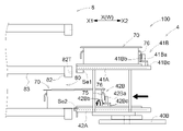
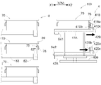
- FIG. 2 is a plan view showing a first posture and a second posture of the transfer device; The figure which shows the transfer apparatus seen from the direction orthogonal to the transfer direction. The figure which shows the locking attitude
- the transport vehicle transports containers that can be stacked vertically.
- an embodiment of the transport vehicle will be described by exemplifying a case where the transport vehicle is provided in transport equipment for transporting containers.
- the transport facility F includes a container shelf 8 for storing containers 70 (see FIG. 3) and a loading/unloading section 9 for loading/unloading the containers 70 .
- the transport vehicle 100 transports the container 70 loaded by the loading/unloading section 9 to the container shelf 8, or transports the container 70 stored on the container shelf 8 to the loading/unloading section 9 for unloading.
- a plurality of container shelves 8 are arranged parallel to each other with a specified interval. Each of the plurality of container shelves 8 has at least an opening at the front, and the container 70 is taken in and out at the front.
- a part of the travel route R of the transport vehicle 100 is set between a pair of container shelves 8 that are adjacent to each other with their front faces facing each other.
- the container shelf 8 arranged at the end of the plurality of container shelves 8 provided in the transfer facility F is arranged with the front facing outward, and the area along the front of the container shelf 8 at the end A part of the travel route R is also set in .
- a plurality of carry-in/out sections 9 are provided in the transport facility F, and a portion of the travel route R is also set in an area passing through each of the plurality of carry-in/out sections 9 .
- the travel route R includes an intra-shelf route Ra extending in the direction in which the container shelf 8 extends along the front surface of the container shelf 8, and an extra-shelf route Rb intersecting the intra-shelf route Ra outside the arrangement area of the container shelf 8. , contains The intra-shelf path Ra is set corresponding to each of the plurality of container shelves 8 .
- a part of the travel route R set in the region corresponds to the intra-shelf route Ra.
- outside-shelf route Rb is set so as to connect a plurality of inside-shelf routes Ra. Further, the off-shelf route Rb is set so as to pass through each of the carrying-in/out sections 9 . In this embodiment, a portion of the travel route R other than the intra-shelf route Ra corresponds to the extra-shelf route Rb.
- the container shelf 8 includes a plurality of shelves 80 for storing containers 70 in the vertical direction.
- the container shelf 8 is configured by combining a plurality of support members 81 and a plurality of beam members 82 .
- a plurality of beam members 82 are arranged at intervals in the vertical direction.
- a mounting member 83 for mounting the container 70 is connected to each of the plurality of beam members 82 .
- the container 70 is stored in the shelf 80 by being placed on a pair of placement members 83 .
- a plurality of pairs of mounting members 83 are arranged on the shelf portion 80 , and a plurality of containers 70 can be accommodated on one shelf portion 80 .
- the region between the pair of support members 81 adjacent in the width direction (horizontal direction) in the front view shown in FIG. 2 and between the pair of beam members 82 adjacent in the vertical direction is the container It corresponds to the opening of the shelf 8 .
- a reference position 80P for storing the container 70 on the shelf 80 is provided with a target portion 82T serving as a target for storing the container 70 at the reference position 80P.
- the target portion 82T is provided on the beam member 82 .
- One target portion 82T is provided for each pair of mounting members 83 .
- the target portion 82T is configured by a hole formed in the beam member 82. As shown in FIG.
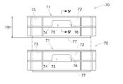
- the container 70 is formed in a box shape having an opening 71 that opens upward and a peripheral wall portion 72 that surrounds the inner space of the container 70 .
- the outer shape of the container 70 when viewed in the up-down direction is rectangular.
- Articles can be accommodated in the inner space surrounded by the peripheral wall portion 72 , that is, the interior of the container 70 .
- Articles include, for example, various commodities such as foodstuffs and daily necessities, or parts and work-in-progress used in factory production lines and the like.
- the container 70 is configured so that it can be stacked with another container 70 with the articles stored therein. That is, the container 70 is configured to be vertically stackable (see also FIG. 5).
- the container 70 has a fitting portion 77 projecting downward from its bottom. The two containers 70 are vertically stacked by fitting the fitting portion 77 of the container 70 into the opening 71 of another container 70 from above.
- the container 70 has a plurality of ribs projecting outward from the peripheral wall 72 .
- Some of the plurality of ribs are lifting ribs 73 that are lifted by a lifting device 3, which will be described later.
- the lifting rib portion 73 is formed on the upper portion of the peripheral wall portion 72 .
- the lifting rib portion 73 is formed along the entire circumference of the portion surrounding the opening 71 in the peripheral wall portion 72 .
- Some of the plurality of rib portions are transfer rib portions 74 that are lifted during the transfer operation by the transfer device 4, which will be described later. In this example, the transfer rib portion 74 is formed below the lifting rib portion 73 .
- the container 70 has a recess 75 .
- the concave portion 75 is formed on the surface of the container 70 on which the transfer rib portion 74 is provided.
- the container 70 has a locking wall 76 projecting outward from the peripheral wall portion 72 and extending downward between the lifting rib portion 73 and the transfer rib portion 74 in the vertical direction.
- a recess 75 is formed between the locking wall 76 and the peripheral wall portion 72 .
- the recessed portion 75 is a space surrounded by the peripheral wall portion 72 and the locking wall 76 .
- the locking wall 76 is a portion where the first locking portion 41Bb and the second locking portion 42Bb are locked during the transfer operation by the transfer device 4, as will be described later.
- the height of the container 70 is defined as container height 70H.
- the container height 70H is the vertical dimension from the upper end to the lower end of the container 70, and corresponds to the vertical distance from the opening 71 to the lower end of the fitting portion 77 in this embodiment.
- the fitting portion 77 of the upper container 70 fits and fits inside the lower container 70 . Therefore, the total height of the two stacked containers 70 is shorter than the height of the two containers 70 (70H ⁇ 2) by the height of the fitting portion 77 .
- the transport vehicle 100 includes a traveling vehicle 1, a container group supporting portion 2 that supports a plurality of containers 70 as a stacked container group 7 within a prescribed stacking area 2A, a container A lifting device 3 that lifts the container 70 of the container group 7 supported by the group support part 2 and a transfer device 4 that transfers the container 70 are provided.
- the container group support section 2 , the lifting device 3 and the transfer device 4 are mounted on the traveling body 1 .
- the container group supporting section 2 and the transfer device 4 are arranged side by side in the vehicle longitudinal direction L on the traveling body 1 .
- the direction orthogonal to the vehicle body front-back direction L when viewed in the vertical direction is referred to as the "vehicle width direction W".
- the transport vehicle 100 is provided with a control device C.
- the control device C controls each functional unit of the transport vehicle 100 .
- the control device C controls the traveling body 1, the container group support section 2, the lifting device 3, the transfer device 4, and the turning device 5, which will be described later.
- the operation for transporting and transferring the container 70 is realized by the control of each functional unit by the control device C.
- the control device C includes, for example, a processor such as a microcomputer, peripheral circuits such as a memory, and the like. Each function is realized through cooperation between these hardware and a program executed on a processor such as a computer.
- the traveling body 1 is configured to travel along a prescribed travel route R (see FIG. 1). In this embodiment, the traveling body 1 is configured to travel along an intra-shelf route Ra and an extra-shelf route Rb. The traveling body 1 is configured to travel along the container shelf 8 when traveling along the intra-shelf route Ra, and more specifically, is configured to travel along the front surface of the container shelf 8 . In this embodiment, the traveling body 1 is configured to travel on the floor surface.
- the traveling body 1 includes a plurality of traveling wheels 10 and a traveling drive section 10M that drives at least one of the plurality of traveling wheels 10.
- the traveling drive unit 10M includes a motor (not shown). By driving the traveling wheels 10 by the traveling drive unit 10M, the traveling body 1 is provided with a driving force in the traveling direction.
- the container group supporting portion 2 is mounted on the traveling body 1 .
- the container group support part 2 is configured to be able to support a plurality of containers 70 as a stacked container group 7 .
- a stacking area 2 ⁇ /b>A in which the container group 7 is arranged is defined above the container group support portion 2 .
- the stacking area 2A is a three-dimensional imaginary area extending upward from the container group supporting portion 2.
- the container group supporting section 2 is configured as a conveyor capable of moving the container group 7 while the container group 7 is placed thereon.
- the container group supporting portion 2 is capable of moving the container group 7 along the width direction W of the vehicle body.
- Conveyors constituting the container group supporting section 2 may be known conveyors such as roller conveyors, chain conveyors, and belt conveyors.
- a container group 7 in which a plurality of containers 70 are stacked is carried into the loading/unloading section 9 (see FIG. 1).
- the container group supporting section 2 receives the container group 7 from the loading/unloading section 9 or delivers the container group 7 to the loading/unloading section 9 while the traveling body 1 is adjacent to the loading/unloading section 9 . That is, the container group supporting section 2 is configured to transfer the container group 7 to and from the carry-in/out section 9 .
- the loading/unloading section 9 is adjacent to the picking area where the work of taking out articles from the container 70 is performed.
- the containers When the container group 7 is handed over from the container group supporting section 2 to the loading/unloading section 9 , the articles are taken out from the container 70 in the picking area adjacent to the loading/unloading section 9 . After some or all of the articles stored in the container 70 are taken out, the container 70 is handed over from the loading/unloading section 9 to the container group support section 2 (the transport vehicle 100) and transported to the container shelf 8 again. be.
- the loading/unloading section 9 does not have to be adjacent to the picking area, and may be adjacent to other equipment or work areas. Further, for example, the loading/unloading section 9 may be configured to transport the container group 7 handed over from the container group support section 2 to the outside of the transport facility F.
- a lifting device 3 is mounted on the traveling body 1 .
- the lifting device 3 is configured to lift the containers 70 of the container group 7 supported by the container group supporting portion 2, in other words, the containers 70 of the container group 7 arranged in the stacking area 2A.
- the lifting device 3 includes a lifting mast 30 erected upward from the traveling body 1 , a lifting elevating body 30 B connected to the lifting mast 30 , and elevating the lifting elevating body 30 B along the lifting mast 30 . and a lift driving unit 30M for lifting.
- the lifting elevator body drive unit 30M includes, for example, an endless body such as a belt connected to the lifting elevator body 30B, a rotating body around which the endless body is wound, and the rotating body and a motor that rotates the
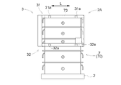
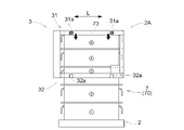
- the lifting device 3 includes a first lifting mechanism 31 for lifting a container 70 at an arbitrary height among the container group 7 stacked in the stacking area 2A with respect to the container 70 adjacent below the container 70; and a second lifting mechanism 32 for lifting the container 70 below the container 70 lifted by the first lifting mechanism 31 with respect to the container 70 adjacent below the container 70 .
- the first lifting mechanism 31 and the second lifting mechanism 32 are arranged apart from each other in the vertical direction. As a result, for example, as shown in FIG. 25, it is possible to form a vertical space between the container 70 lifted by the first lifting mechanism 31 and the container 70 lifted by the second lifting mechanism 32. It has become. In addition, it is possible to form a vertical space below the container 70 lifted by the second lifting mechanism 32 .
- the lifting device 3 includes a first frame portion 31F and a second frame portion 32F projecting in the longitudinal direction L of the vehicle body from the lifting body 30B toward the stacking area 2A, and the first frame portion 31F and the second frame portion 32F. and a connection frame portion 33F that connects the two frame portions 32F.
- the first frame portion 31F and the second frame portion 32F are arranged with a space therebetween in the vertical direction.
- the first frame portion 31F is arranged above the second frame portion 32F.
- the connecting frame portion 33F vertically connects the first frame portion 31F and the second frame portion 32F.
- first frame portion 31F and the second frame portion 32F do not move relative to each other, and the vertical distance between the first frame portion 31F and the second frame portion 32F is always constant. It's becoming The first frame portion 31F, the second frame portion 32F, and the connecting frame portion 33F integrally move up and down as the lifting body 30B moves up and down.
- the first frame portion 31F includes a pair of first frame members 31Fa spaced apart in the width direction W of the vehicle body.
- the pair of first frame members 31Fa are arranged corresponding to the width (the length in the vehicle width direction W) of the container 70 arranged in the stacking area 2A.
- the arrangement interval of the pair of first frame members 31Fa in the width direction W of the vehicle body corresponds to the width of the container 70 .
- the arrangement interval of the pair of first frame members 31Fa in the width direction W of the vehicle body is larger than the width of the container 70 by a prescribed dimension corresponding to the dimension of the first lifting and holding portion 31a described later. ing.
- the second frame portion 32F includes a pair of second frame members 32Fa spaced apart in the width direction W of the vehicle body.
- the pair of second frame members 32Fa are arranged corresponding to the width of the containers 70 arranged in the stacking area 2A.
- the arrangement interval of the pair of second frame members 32Fa in the vehicle body width direction W corresponds to the width of the container 70 .
- the arrangement interval of the pair of second frame members 32Fa in the vehicle body width direction W is larger than the width of the container 70 by a prescribed dimension corresponding to the dimension of the second lifting/holding portion 32a, which will be described later. ing.
- the connecting frame portion 33F includes a pair of connecting frame members 33Fa.
- Each of the pair of connecting frame members 33Fa connects the first frame member 31Fa and the second frame member 32Fa that are arranged in the vertical direction.
- the first lifting mechanism 31 has a first lifting/holding part 31 a that holds the container 70 .
- the first lifting mechanism 31 also includes a first lifting drive section 31M that changes the posture of the first lifting and holding section 31a between a holding posture for holding the container 70 and a non-holding posture for not holding the container 70. .
- the first lifting/holding portion 31a is configured to rotate about an axis along the longitudinal direction L of the vehicle body.
- the first lifting/holding portion 31a is arranged at a position overlapping with the lifting rib portion 73 of the container 70 in the stacking region 2A in the holding posture in the vertical view, and in the non-holding posture, the lifting rib portion 73 and the lifting rib portion 31a overlap each other. It retreats to the outside in the width direction W of the vehicle body from the overlapping position when viewed from the direction.
- the holding posture of the first lifting/holding portion 31a is indicated by a solid line
- the non-holding posture of the first lifting/holding portion 31a is indicated by an imaginary line. In this manner, the first lifting/holding portion 31a in the holding posture is arranged to face the lifting rib portion 73 from below. In this state, the container 70 is lifted by raising the first frame portion 31F.
- the first lifting mechanism 31 includes the above-described first frame portion 31F, and the first lifting/holding portion 31a is supported by the first frame portion 31F. Specifically, the first lifting/holding portion 31a is supported by each of a pair of first frame members 31Fa spaced apart in the width direction W of the vehicle body. In this manner, the first lifting mechanism 31 includes a pair of first lifting/holding portions 31a spaced apart in the width direction W of the vehicle body. The arrangement interval in the width direction W of the vehicle body of the pair of first lifting/holding portions 31a corresponds to the width of the containers 70 arranged in the stacking area 2A.
- the second lifting mechanism 32 includes a second lifting/holding portion 32a that is arranged below the first lifting/holding portion 31a and holds the container 70.
- the second lifting mechanism 32 includes a second lifting driving portion 32M that changes the posture of the second lifting/holding portion 32a between a holding posture for holding the container 70 and a non-holding posture for not holding the container 70 .
- the second lifting/holding portion 32a is configured to rotate about an axis along the longitudinal direction L of the vehicle body.
- the second lifting/holding portion 32a is arranged at a position overlapping the lifting rib portion 73 of the container 70 in the stacking region 2A in the holding posture in the vertical view, and in the non-holding posture, the lifting rib portion 73 and the lifting rib portion 73 overlap each other. It retreats to the outside in the width direction W of the vehicle body from the overlapping position when viewed from the direction.
- the holding posture of the second lifting/holding portion 32a is indicated by a solid line
- the non-holding posture of the second lifting/holding portion 32a is indicated by a virtual line. In this manner, the second lifting/holding portion 32a in the holding posture is arranged to face the lifting rib portion 73 from below. In this state, the container 70 is lifted by raising the second frame portion 32F.
- the second lifting mechanism 32 includes the above-described second frame portion 32F, and the second lifting/holding portion 32a is supported by the second frame portion 32F. Specifically, the second lifting/holding portion 32a is supported by a pair of second frame members 32Fa spaced apart in the width direction W of the vehicle body. In this manner, the second lifting mechanism 32 includes a pair of second lifting/holding portions 32a spaced apart in the width direction W of the vehicle body. The arrangement interval in the width direction W of the vehicle body of the pair of second lifting/holding portions 32a corresponds to the width of the containers 70 arranged in the stacking area 2A.
- another container 70 can be transferred between the container 70 lifted by the first lifting mechanism 31 and the container 70 lifted by the second lifting mechanism 32 in the vertical direction. space is formed. As a result, another container 70 can be transferred to the space by the transfer device 4 (see FIG. 5). In other words, it is possible for the transfer device 4 to stack another container 70 on top of the container 70 lifted by the second lifting mechanism 32 .
- the second lifting mechanism 32 is provided with a guide portion 3G that guides the container 70 transferred by the transfer device 4.
- the guide portion 3G includes a pair of guide members 3Ga spaced apart in the width direction W of the vehicle body.
- the arrangement interval of the pair of guide members 3Ga in the width direction W of the vehicle body corresponds to the width of the container 70.
- each of the pair of second frame members 32Fa is provided with a guide member 3Ga.
- the guide member 3Ga is formed in a plate shape rising upward from the second frame member 32Fa, and guides the container 70 with a plate surface facing inward in the width direction W of the vehicle body.
- the transfer operation of the container 70 by the transfer device 4 includes the operation of moving the container 70 in the horizontal direction and the operation of moving the container 70 in the vertical direction.
- the vertical interval 3H between the first lift-holding portion 31a and the second lift-holding portion 32a is set to the height of N stages of the container 70 (N is an integer equal to or greater than 2). It is set according to the height including the vertical movement amount Mv of the container 70 to be transferred during the transfer operation by (the second transfer device 42B described later in detail). "N" is preset and is set to "2" in this example.
- the transfer device 4 is mounted on the traveling body 1 .
- the transfer device 4 is configured to transfer the container 70 to a transfer target location.
- the transfer device 4 is configured to perform an unloading operation for transferring the container 70 to the transfer target location and a scooping operation for transferring the container 70 from the transfer target location.
- the transfer target location includes the stacking area 2A and the shelf portion 80 of the container shelf 8 .
- the movement direction of the container 70 transferred by the transfer device 4 is defined as the transfer direction X.
- one side in the transfer direction X is defined as the transfer direction unloading side X1
- the other side is defined as the transfer direction scooping side X2.
- the transfer direction X is a direction along the horizontal direction.
- the transfer direction unloading side X1 is the side where the container 70 moves along the transfer direction X when the container 70 is unloaded.
- the transfer direction scooping side X2 is the side where the container 70 moves along the transfer direction X when the container 70 is scooped.
- the transport vehicle 100 includes a turning device 5 that turns the transfer device 4 around an axis along the vertical direction.
- the turning device 5 turns the transfer device 4 (specifically, a part of the transfer device 4) about an axis extending in the vertical direction so that the transfer direction X is shifted to the stacking area 2A. and a second posture P2 in which the transfer direction X is directed toward the container shelf 8.
- the transfer direction X can be changed within the horizontal plane by the turning device 5 .
- the transfer device 4 changes its posture according to the position of the transfer target location. Specifically, the transfer device 4 assumes the first posture P1 when the transfer target location is the stacking area 2A, and the second posture P1 when the transfer target location is the container shelf 8 (shelf portion 80). becomes P2.
- the swivel device 5 is mounted on a swivel table 50 that supports the transfer device 4 (specifically, a part of the transfer device 4) and a transfer lifting body 40B, which will be described later.
- a swivel shaft 51 that rotatably supports the swivel base 50 and a swivel drive unit 5 ⁇ /b>M that drives the swivel shaft 51 are provided.
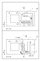
- FIGS. 10 and 11 show the cases where the transfer device 4 is in the first posture P1.
- the lifting device 3 that actually lifts the container 70 is omitted for better visibility.
- the transfer device 4 includes a transfer mast 40 erected above the traveling body 1, a transfer elevating body 40B connected to the transfer mast 40, a transfer and a transfer lifting body driving section 40M that moves the lifting body 40B up and down along the transfer mast 40 .
- the transfer elevator body driving section 40M includes, for example, an endless body such as a belt connected to the transfer elevator body 40B, a rotating body around which the endless body is wound, and the and a motor that rotates the rotating body.
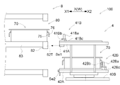
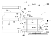
- the transfer device 4 includes a first holding portion 41A that holds the container 70, a second holding portion 42A that is arranged below the first holding portion 41A and holds the container 70, and a second holding portion 42A that holds the container 70.
- a first transfer device 41B that transfers the container 70 between the first holding unit 41A and the transfer target location, and a transfer device 41B that transfers the container 70 between the second holding unit 42A and the transfer target location. and a second transfer machine 42B for carrying out.
- the transfer target location includes the stacking area 2A and the shelf portion 80 of the container shelf 8. That is, the first transfer device 41B transfers the container 70 between the first holding section 41A and the stacking area 2A or the shelf section 80.
- the second transfer device 42B transfers the container 70 between the second holding section 42A and the stacking area 2A or the shelf section 80.
- the first transfer device 41B transfers the container 70 between the first holding section 41A and the stacking area 2A in the state of the first attitude P1 (see FIGS. 10 and 11, etc.). ), and the container 70 is transferred between the first holding portion 41A and the shelf portion 80 in the state of the second posture P2 (see FIG. 8, etc.).
- the second transfer device 42B transfers the container 70 between the second holding section 42A and the stacking area 2A in the state of the first posture P1 (see FIGS. 10 and 11, etc.), The container 70 is transferred between the second holding portion 42A and the shelf portion 80 in the state of the second posture P2 (see FIG. 8, etc.).
- the transfer device 4 includes a holding connecting portion 43 that vertically connects the first holding portion 41A and the second holding portion 42A.
- the holding connecting portion 43 connects the first holding portion 41A and the second holding portion 42A so that the vertical interval between them is constant.
- the transfer device 4 includes a first holding drive unit 41MA that moves the first holding unit 41A along the transfer direction X, and a second holding unit 41MA that moves the second holding unit 42A along the transfer direction X. 2 holding drive unit 42MA.
- the first holding drive section 41MA is configured to relatively move the first holding section 41A along the transfer direction X with respect to the transfer lifting body 40B.
- the second holding drive section 42MA is configured to relatively move the second holding section 42A along the transfer direction X with respect to the transfer lifting body 40B.
- the first holding portion 41A and the second holding portion 42A are connected by the holding connection portion 43 in the present embodiment. Therefore, the first holding portion 41A and the second holding portion 42A move along the transfer direction X integrally.
- the first holding drive section 41MA that drives the first holding section 41A and the second holding drive section 42MA that drives the second holding section 42A are configured to be driven by a common drive source.
- the first transfer device 41B performs the first pressing portion 41Ba that presses the container 70 toward the unloading side X1 in the transfer direction and the scooping operation of the container 70 when performing the unloading operation of the container 70. and a first locking portion 41Bb that is locked to the container 70 when the container 70 is closed.
- Each of the first pressing portion 41Ba and the first locking portion 41Bb is configured to be relatively movable along the transfer direction X with respect to the first holding portion 41A.
- the first transfer device 41B includes a first supporting member 41Bc supported by the first holding portion 41A and supporting the first pressing portion 41Ba and the first locking portion 41Bb, and a first supporting member 41Bc. and a first transfer driving section 41Mc that relatively moves the member 41Bc along the transfer direction X with respect to the first holding section 41A.
- the first support member 41Bc is driven by the first transfer driving section 41Mc, so that the first pressing section 41Ba and the first locking section 41Bb move toward the first holding section 41A in the transfer direction X. Relative movement along
- the first pressing portion 41Ba and the first locking portion 41Bb are configured to move along the transfer direction X integrally.
- the movable range along the transfer direction X of the first pressing portion 41Ba and the first locking portion 41Bb is larger than the movable range along the transfer direction X of the first holding portion 41A.
- the first holding portion 41A is moved close to the transfer target location.
- the container 70 is transferred using the pressing portion 41Ba or the first locking portion 41Bb.
- the gap between the first holding portion 41A and the transfer target portion can be reduced during the transfer operation, and the container 70 can be stably transferred by the first transfer device 41B.
- the second transfer machine 42B performs the second pressing portion 42Ba that presses the container 70 toward the unloading side X1 in the transfer direction and the scooping operation of the container 70 when performing the unloading operation of the container 70. and a second locking portion 42Bb that is locked to the container 70 when the container 70 is closed.
- Each of the second pressing portion 42Ba and the second locking portion 42Bb is configured to be relatively movable along the transfer direction X with respect to the second holding portion 42A.
- the second transfer device 42B includes a second supporting member 42Bc supported by the second holding portion 42A and supporting the second pressing portion 42Ba and the second locking portion 42Bb, and a second supporting member 42Bc. and a second transfer driving section 42Mc that relatively moves the member 42Bc along the transfer direction X with respect to the second holding section 42A.
- the second support member 42Bc is driven by the second transfer drive section 42Mc, so that the second pressing section 42Ba and the second locking section 42Bb are moved in the transfer direction X with respect to the second holding section 42A. Relative movement along
- the second pressing portion 42Ba and the second locking portion 42Bb are configured to move along the transfer direction X integrally. Further, the movable range along the transfer direction X of the second pressing portion 42Ba and the second locking portion 42Bb is larger than the movable range along the transfer direction X of the second holding portion 42A.
- the second holding portion 42A is moved close to the transfer target location. The container 70 is transferred using the pressing portion 42Ba or the second locking portion 42Bb. As a result, the gap between the second holding portion 42A and the transfer target portion can be reduced during the transfer operation, and the container 70 can be stably transferred by the second transfer device 42B.
- the first transfer device 41B includes a first locking drive section 41Mb that drives the first locking section 41Bb.
- the first lock driving portion 41Mb rotationally drives the first lock portion 41Bb about the rotation axis along the transfer direction X.
- the second transfer device 42B includes a second locking drive section 42Mb that drives the second locking section 42Bb.
- the second locking driving portion 42Mb rotationally drives the second locking portion 42Bb about the rotation axis along the transfer direction X. As shown in FIG.
- the first locking portion 41Bb is rotationally driven by the first locking drive portion 41Mb, and thus has a locking posture of being inserted into the recess 75 of the container 70 and a non-engagement posture of coming out of the recess 75. As shown in FIG. It is configured so that the posture can be changed between the stationary posture and the posture.
- the first locking portion 41Bb in the locking posture is arranged between the peripheral wall portion 72 and the locking wall 76 in the transfer direction X in the recess 75 .
- the second locking portion 42Bb is rotationally driven by the second locking driving portion 42Mb, and thus has a locking posture in which it is inserted into the recess 75 of the container 70, a non-locking posture in which it comes out of the recess 75, It is configured so that the posture can be changed to
- the second locking portion 42Bb in the locking posture is arranged between the peripheral wall portion 72 and the locking wall 76 in the transfer direction X in the recess 75 .
- FIG. 10 and 11 the container 70 is shown in a simplified manner.
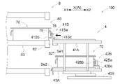
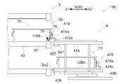
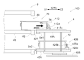
- 10 and 11 show the operation when the transfer device 4 transfers the container 70 to the stacking area 2A as the transfer target location. 10 shows the unloading operation of the container 70 by the transfer device 4, and FIG. 11 shows the scooping operation of the container 70 by the transfer device 4. As shown in FIG. Even when the shelf portion 80 of the container shelf 8 is the location to be transferred, the transfer device 4 operates in substantially the same manner. Further, the transfer operation of the container 70 by the first transfer device 41B and the transfer operation of the container 70 by the second transfer device 42B are the same. Therefore, with reference to FIGS. 10 and 11, the transfer operations by the respective transfer devices 41B and 42B will be collectively described.
- the first holding section 41A and the second holding section 42A are collectively referred to as "holding section A”
- the first transfer machine 41B and the second transfer machine 42B are collectively called “transfer machine B”
- the first pressing portion 41Ba and the second pressing portion 42Ba are collectively referred to as “pressing portion Ba”
- the first locking portion 41Bb and the second locking portion 42Bb are collectively referred to as “locking portion Bb”
- the first supporting member 41Bc. and the second support member 42Bc are collectively referred to as "support member Bc”.
- 10 and 11 the first transfer device 41B and the second transfer device 42B are illustrated without particular distinction, and sensors Se1 and Se2 and a regulation unit 44, which will be described later, are omitted.
- the pressing part Ba presses the container 70 toward the unloading side X1 in the transfer direction.
- the pressing portion Ba presses the container 70 toward the unloading side X1 in the loading direction while being in contact with the locking wall 76 of the container 70 from the scooping side X2 in the loading direction. do.
- the container 70 to be unloaded held by the holding section A moves from the holding section A to the stacking area 2A.
- the holding part A when the transfer machine B unloads the container 70 with respect to the stacking area 2A, the holding part A is moved up and down. Specifically, at the start of the unloading operation, the holding part A has the lower end (lower surface) of the container 70 to be unloaded higher than the upper end (upper surface) of the other containers 70 in the stacking area 2A to be unloaded. It is placed at the unloading operation start height set to a height such that it is located at Here, the unloading operation start height is the height at which the lower surface of the fitting portion 77 of the container 70 to be unloaded is located above the upper surface of the opening 71 of the other container 70 in the stacking area 2A by a specified amount.
- the holding part A descends to the unloading operation completion height set below the unloading operation start height, and lifts the container 70 to be unloaded. , are stacked on top of other containers 70 arranged in the stacking area 2A.
- the fitting part 77 of the container 70 to be unloaded is brought close to the opening part 71 of the other container 70 arranged in the stacking area 2A from above. can be fitted to
- Such vertical movement of the holding portion A is realized by the vertical movement of the transfer elevator 40B (see FIG. 5).
- the container 70 is drawn in toward the scooping side X2 in the transfer direction by the engaging portion Bb.
- the locking portion Bb assumes the locking posture when the scooping operation is performed, and the container 70 is moved while being in contact with the locking wall 76 of the container 70 from the transfer direction unloading side X1. Pull in toward the scooping side X2 in the loading direction.
- the containers 70 to be scooped and placed in the stacking area 2A are moved from the stacking area 2A to the holding portion A.
- FIG. 11 when the transfer machine B performs the scooping operation, the container 70 is drawn in toward the scooping side X2 in the transfer direction by the engaging portion Bb.
- the locking portion Bb assumes the locking posture when the scooping operation is performed, and the container 70 is moved while being in contact with the locking wall 76 of the container 70 from the transfer direction unloading side X1. Pull in toward the scooping side X2 in the loading direction.
- the containers 70 to be scooped and placed in the stacking area 2A are moved
- the holding part A when the transfer machine B scoops up the container 70 in the stacking area 2A, the holding part A is moved up and down. Specifically, at the start of the scooping operation, the locking portion Bb and the support member Bc in the non-locking posture are set to a height lower than the transfer rib portion 74 and the locking wall 76. It is placed at the scooping operation start height. Next, after the locking portion Bb is in the locking posture, the holding portion A rises to the scooping operation completion height set above the scooping operation start height, and the locking portion Bb of the container 70 is Lift the locked part. In this example, as shown in FIG.
- the supporting member Bc (first supporting member 41Bc, second supporting member 42Bc) supporting the locking portion Bb (first locking portion 41Bb, second locking portion 42Bb) is , contact the transfer rib portion 74 of the container 70 from below to lift the container 70 .
- the engaging portions Bb (the first engaging portion 41Bb and the second engaging portion 42Bb) do not participate in lifting the container 70 .
- the support member Bc the first support member 41Bc and the second support member 42Bc
- the container 70 to be scooped is inclined upward toward the scooping side X2 in the transfer direction. 29 (see, for example, FIG. 29).
- the scooping operation completion height is such that the end of the transfer direction scooping side X2 on the lower surface of the fitting portion 77 of the scooping target container 70 is arranged adjacent to the lower side of the scooping target container 70. It has a height that is positioned above the upper surface of the opening 71 of the other container 70 by a prescribed amount. As a result, the end portion on the transfer direction scooping side X2 of the fitting portion 77 of the container 70 to be scooped can be removed from the opening portion 71 of the other container 70 arranged adjacently therebelow. The fitting between 70 can be properly released.
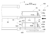
- the locking portion Bb and the support member Bc move relative to the holding portion A toward the scooping side X2 in the transfer direction, thereby moving the container 70 to be scooped from the stacking region 2A to the holding portion A.
- Such vertical movement of the holding portion A is realized by the vertical movement of the transfer elevator 40B (see FIG. 5).
- the transfer device 4 moves the container 70 not only in the transfer direction X but also in the vertical direction, thereby transferring the container 70 to the stacking area 2A. As a result, it is possible to perform the transfer operation while appropriately performing the fitting and releasing of the fitting between the containers 70 .
- the transfer device 4 performs the transfer operation with respect to the shelf portion 80 of the container shelf 8, it is irrelevant to the fitting of the containers 70 to each other. Only the container 70 may be moved.
- the holding section A is provided with a transfer machine side guide section 4G that guides the container 70 to be transferred in the transfer direction X.
- the transfer-device-side guide portions 4G are provided at both ends of the holding portion A in the direction perpendicular to the transfer direction X, and guide both side surfaces (both sides in the direction perpendicular to the transfer direction X) of the container 70 to be transferred. outwardly facing surface).
- the transfer device side guide portion 4G is provided in each of the first holding portion 41A and the second holding portion 42A (see FIG. 8).
- the vertical interval 4H between the first holding portion 41A and the second holding portion 42A is equal to the height of N stages of the container 70 (N is an integer equal to or greater than 2).
- This interval is equal to or greater than the height of the vertical movement amount Mv of the container 70 to be transferred during the transfer operation by (specifically, the second transfer device 42B).
- the above "N" is set to "2”
- the vertical interval 4H between the first holding portion 41A and the second holding portion 42A is the height of two stages of the container 70.
- the vertical distance 4H between the first holding portion 41A and the second holding portion 42A corresponds to the vertical movement amount Mv of the container 70 to be transferred during the transfer operation by the second transfer device 42B. being considered.
- the fitting portion 77 is formed in the bottom portion of the container 70, and the fitting portion 77 is fitted into the opening portion 71 of the container 70 below. Therefore, the second transfer device 42B needs to move the container 70 up and down more than the vertical dimension of the fitting portion 77 both when the container 70 is unloaded and when the container 70 is scooped. That is, in the present embodiment, the vertical movement amount Mv is set larger than the vertical dimension of the fitting portion 77 of the container 70 .
- the second transfer device 42B transfers the container 70 adjacent below the container 70 lifted by the second lifting mechanism 32 to the second holding section 42A.
- the first transfer device 41B lifts the container 70 held by the first holding part 41A by the second lifting mechanism 32 while the second holding part 42A is arranged at a height for (scooping).
- the vertical distance 4H between the first holding portion 41A and the second holding portion 42A is set so that the first holding portion 41A is arranged at a height for transferring (unloading) the upper portion 70 (see FIG. 8). is set.
- the scooping operation and unloading operation of the containers 70 with respect to the stacking area 2A can be performed in parallel (see FIGS. 30 and 31).
- the transfer device 4 is provided with a restricting section 44.
- the regulating unit 44 is configured to prevent the container 70 adjacent to and below the scooping target container 70. 2 holding part 42A side is opposingly arranged, and it is comprised so that the movement to the 2nd holding
- the container 70 on the third level from the bottom in the stacking area 2A is the container 70 to be scooped
- the container 70 on the second level from the bottom is the container 70 to be regulated by the regulating section 44 .
- the container 70 to be scooped that moves toward the second holding portion 42A interferes with the adjacent container 70 (adjacent container 70) below and is second held by the adjacent container 70.
- the adjacent container 70 and the plurality of containers 70 stacked below the adjacent container 70 can be prevented from falling or moving toward the second holding portion 42A. can.
- the restricting portion 44 is attached to the second holding portion 42A and arranged below the second locking portion 42Bb.
- the restricting portion 44 is attached to the end of the second holding portion 42A on the unloading side X1 in the transfer direction.
- the second locking portion 42Bb is supported by the second support member 42Bc and configured to move along the transfer direction X together with the second support member 42Bc. And this 2nd support member 42Bc moves relatively with respect to 2nd holding
- the restricting portion 44 is moved under the container 70 to be scooped while moving the second locking portion 42Bb toward the second holding portion 42A. can be held at a position facing the container 70 adjacent to the second holding portion 42A side. Therefore, while properly scooping the container 70 to be scooped, the container 70 adjacent to the bottom of the container 70 to be scooped and the plurality of containers 70 stacked below it are prevented from falling toward the second holding portion 42A. It can be appropriately regulated (see FIGS. 30 and 31).
- the restricting portion 44 may be stopped on the spot, or may be moved in the direction opposite to the moving direction of the second locking portion 42Bb. It may move to the unloading side X1 in the transfer direction, or may move to the scooping side X2 in the transfer direction at a lower speed than the second locking portion 42Bb.
- the transfer device 4 includes a reference position detection sensor Se1 for detecting a reference position 80P (see FIG. 2) for storing the container 70 on the shelf 80, and a storage container detection sensor Se2 for detecting the container 70 stored in the container.
- the target portion 82T is provided at the reference position 80P of the shelf portion 80.
- the reference position detection sensor Se1 is configured to detect the positional relationship between the transfer device 4 having the reference position detection sensor Se1 and the reference position 80P of the shelf 80 by detecting the target portion 82T. It is configured. Then, based on the detection result of the target portion 82T by the reference position detection sensor Se1, the moving body 1, the turning device 5, and the transfer lifting body drive section 40M of the transfer device 4 are controlled to By performing the operation of correcting the position, it is possible to properly transfer the container 70 to the shelf 80 .
- the reference position detection sensor Se1 is composed of a camera.
- the positional relationship between the transfer device 4 and the target portion 82T provided on the beam member 82 can be detected by image recognition of the reference position detection sensor Se1 configured as a camera. Further, in this example, the reference position detection sensor Se1 also functions as a ranging sensor that detects the distance to the object. When the transfer device 4 transfers the container 70 to the transfer target location, the reference position detection sensor Se1 detects the distance from the transfer target location. This makes it possible to perform a transfer operation with high certainty.
- the storage container detection sensor Se2 detects the presence or absence of the container 70 on the shelf 80 to be transferred when the transfer device 4 performs the unloading operation of transferring the container 70 to the shelf 80 .
- the transfer device 4 unloads the container 70 onto the shelf 80 concerned.
- the storage container detection sensor Se2 detects that there is a container 70 on the target shelf 80 to be unloaded, the container 70 may be transferred to another empty shelf 80, Alternatively, the transfer may be stopped.
- the storage container detection sensor Se2 may also be configured as a distance sensor that detects the distance to the target.
- the transfer operation can be performed while measuring the distance between the transfer device 4 and the transfer target location.
- the storage container detection sensor Se2 is configured as an optical sensor that projects light toward the target.
- the configuration is not limited to this, and the storage container detection sensor Se2 may be configured using known means such as an ultrasonic sensor or a camera.
- the reference position detection sensor Se1 is provided in one of the set of the first holding section 41A and the first transfer device 41B and the set of the second holding section 42A and the second transfer device 42B.
- the storage container detection sensor Se2 is provided with a reference position detection sensor Se1 for the set of the first holding section 41A and the first transfer device 41B and the set of the second holding section 42A and the second transfer device 42B. not provided in the other set.
- the reference position detection sensor Se1 is provided in the set of the first holding section 41A and the first transfer device 41B.
- the reference position detection sensor Se1 is provided in the first holding portion 41A. Note that the reference position detection sensor Se1 may be provided in the first transfer device 41B.
- the storage container detection sensor Se2 is provided in the set of the second holding section 42A and the second transfer device 42B.
- the storage container detection sensor Se2 is provided in the second holding portion 42A.
- the storage container detection sensor Se2 may be provided in the second transfer device 42B.
- the transfer device 4 is configured to scoop up the container 70 on the shelf portion 80 of the container shelf 8 .
- the scooping operation of the container 70 on the shelf 80 will be described below with reference to FIGS. 12 to 17.
- FIG. 12 to 17 the first locking portion 41Bb or the second locking portion 42Bb in the locking posture are shown in gray, and the first locking portion 41Bb or the second locking portion 42Bb in the non-locking posture are shown in gray. Shown in white.
- a case of scooping up the container 70 stored in the shelf 80 by the first transfer device 41B will be described as an example. The same applies to the scooping operation performed by the second transfer device 42B.
- the control device C adjusts the shelf 80 to an appropriate position with respect to the reference position 80P based on the detection result of the target portion 82T by the reference position detection sensor Se1. , the position of the first transfer device 41B is aligned.
- the transport vehicle 100 may include an angle sensor that detects the angle of the first transfer device 41B in the horizontal plane. In this case, the angle sensor detects the angle of the first transfer device 41B with respect to the shelf 80. FIG. Then, based on the detection result of the angle sensor, the control device C adjusts the angle of the first transfer device 41B so that the angle with respect to the shelf 80 is appropriate.
- the control device C adjusts the position and angle of the first transfer device 41B by controlling the moving body 1, the turning device 5, and the transfer lifting body driving section 40M of the transfer device 4. FIG. Then, when the first transfer device 41B is in an appropriate positional relationship with respect to the shelf 80, the control device C causes the first transfer device 41B to scoop up the container 70 stored in the shelf 80. to start.
- the control device C moves the first holding part 41A and the second holding part 42A relative to the transfer lifting body 40B in the transfer direction unloading side X1.
- the first holding section 41A and the second holding section 42A, and the first transfer device 41B and the second transfer device 42B approach the shelf section 80 .
- the close distance to the shelf portion 80 is detected by the reference position detection sensor Se1 that also functions as a distance measuring sensor. Therefore, the first holding section 41A and the second holding section 42A, and the first transfer device 41B and the second transfer device 42B should be brought close to the shelf 80 at an appropriate distance for performing the transfer operation. can be done.
- the control device C moves the first locking portion 41Bb relative to the first holding portion 41A toward the unloading side X1 in the transfer direction.
- the first engaging portion 41Bb is arranged at a position below the recess 75 in the container 70 and overlapping the recess 75 in a vertical view (hereinafter referred to as "immediately below the recess 75").
- the first locking portion 41Bb is in the non-locking posture.
- the control device C puts the first locking portion 41Bb in the locking posture with the first locking portion 41Bb arranged directly below the recess 75 .
- the first locking portion 41Bb is inserted into the concave portion 75, and the first locking portion 41Bb is arranged to face the locking wall 76 in the transfer direction unloading side X1.
- the control device C moves the first locking portion 41Bb in the locking posture to the scooping side X2 in the transfer direction with respect to the first holding portion 41A while contacting the locking wall 76 . move relative to As a result, the first locking portion 41Bb pulls the container 70 stored in the shelf portion 80 into the first holding portion 41A.
- the control device C moves the first holding portion 41A and the second holding portion 42A while the container 70 scooped by the first transfer device 41B is held by the first holding portion 41A. , relative to the transfer lifting body 40B in the transfer direction scooping side X2 and returned to the original position.
- the first holding section 41A and the second holding section 42A, and the first transfer device 41B and the second transfer device 42B are separated from the shelf section 80 .
- the control device C maintains the locking posture of the first locking portion 41Bb while the container 70 is held by the first holding portion 41A.
- the control device C maintains the locking posture of the second locking portion 42Bb while the second holding portion 42A holds the container 70 .
- the container 70 can be stably held so as not to move in the transfer direction X.
- the scooping action of the container 70 on the shelf 80 is performed.
- the scooping operation is performed by the control device C controlling each functional unit of the transport vehicle 100 as described above.
- the transfer device 4 is configured to unload the container 70 from the shelf portion 80 of the container shelf 8 .
- the unloading operation of the container 70 with respect to the shelf 80 will be described with reference to FIGS. 18 to 20.
- FIG. 18 to 20 the first locking portion 41Bb or the second locking portion 42Bb in the locking posture are shown in gray, and the first locking portion 41Bb or the second locking portion 42Bb in the non-locking posture are shown in gray. Shown in white.
- a case where the container 70 is unloaded onto the shelf section 80 by the second transfer device 42B will be described as an example. The same applies to the unloading operation performed by the first transfer device 41B.
- the second transfer is performed on the shelf portion 80 immediately below the shelf portion 80 that has performed the scooping operation. It is assumed that the container 70 is unloaded by the loading machine 42B. Therefore, the second transfer device 42B is already in a proper positional relationship with respect to the shelf section 80 .
- the controller C determines the appropriate positional relationship with respect to the shelf 80 based on the detection result of the target portion 82T by the reference position detection sensor Se1. Control may be performed to adjust the position of the second transfer device 42B.
- the control device C moves the first holding portion 41A and the second holding portion 42A relative to the transfer lifting body 40B in the transfer direction unloading side X1.
- the first holding section 41A and the second holding section 42A, and the first transfer device 41B and the second transfer device 42B approach the shelf section 80 .
- the control device C moves the second pressing portion 42Ba relative to the second holding portion 42A in the transfer direction unloading side X1 to move the container 70 to the transfer direction unloading side. Press toward X1.
- the container 70 to be unloaded held by the second holding section 42A is moved from the second holding section 42A to the shelf section 80 .
- the second pressing portion 42Ba presses the container 70 toward the transfer direction unloading side X1 while being in contact with the locking wall 76 of the container 70 from the transfer direction scooping side X2.
- control device C controls the second engaging member that moves to the transfer direction unloading side X1 together with the second pressing portion 42Ba while the unloading target container 70 is moving toward the transfer direction unloading side X1.
- the stopping portion 42Bb is changed from the locking posture to the non-locking posture.
- the control device C moves the second pressing portion 42Ba toward the scooping side X2 in the transfer direction with respect to the second holding portion 42A.
- the first holding portion 41A and the second holding portion 42A are moved relative to the transfer lifting body 40B in the transfer direction scooping side X2 and returned to their original positions.
- the first holding section 41A and the second holding section 42A, and the first transfer device 41B and the second transfer device 42B are separated from the shelf section 80 .
- the unloading operation of the container 70 with respect to the shelf 80 is performed.
- the unloading operation is performed by the control device C controlling each functional unit of the transport vehicle 100 as described above.
- the transfer device 4 is configured to perform the scooping operation and unloading operation of the containers 70 in the stacking area 2A. Specifically, the transfer device 4 is configured to perform a parallel operation in which the containers 70 are scooped up and unloaded in parallel with respect to the stacking area 2A. In the present embodiment, the transfer device 4 performs parallel operations while each of the first lifting mechanism 31 and the second lifting mechanism 32 lifts the container 70 in the stacking area 2A. However, the transfer device 4 can also independently perform the scooping operation and the unloading operation with respect to the stacking area 2A.
- FIG. 21 to 34 the first locking portion 41Bb or the second locking portion 42Bb in the locking posture are shown in gray, and the first locking portion 41Bb or the second locking portion 42Bb in the non-locking posture are shown in gray. Shown in white.
- the first lifting/holding portion 31a of the first lifting mechanism 31 in the holding posture or the second lifting/holding portion 32a of the second lifting mechanism 32 is shown in gray, and the first lifting/holding portion 31a or the second lifting/holding portion 31a in the non-holding posture is shown in gray.
- the lifting holding portion 32a is shown in white.
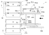
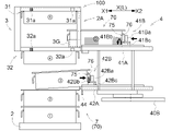
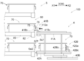
- a case will be described where the container 70 is unloaded to the stacking area 2A by the first transfer device 41B and the container 70 is scooped from the stacking region 2A by the second transfer device 42B.
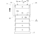
- FIGS. 21 to 34 show an example in which five containers 70 are stacked as a container group 7 in the stacking area 2A.
- the numbers “1 to 5" are attached to the stacked containers 70 in order from the bottom to the top.
- the character “ ⁇ " is attached to the container 70 to be wholesaled held by the first holding portion 41A (see FIG. 25 and the like).
- the control device C places the first lifting/holding part 31a in the non-holding posture at the lifting position for lifting the container 70 to be lifted (container "5").
- the control device C arranges the first lifting/holding part 31a at a position below and adjacent to the lifting rib part 73 of the container 70 to be lifted (container "5").
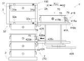
- the control device C raises the first lifting mechanism 31 and the second lifting mechanism 32 with the first lifting/holding portion 31a in the holding posture, thereby performing the first lifting.
- Lift the target container 70 (container "5").
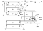
- the control device C arranges the second lifting/holding part 32a in the non-holding posture to the lifting position for lifting the second container 70 to be lifted (container "4").
- the control device C arranges the second lifting/holding part 32a at a position below and adjacent to the lifting rib part 73 of the second container 70 to be lifted (container "4").
- the control device C further raises the first lifting mechanism 31 and the second lifting mechanism 32 with the second lifting/holding portion 32a in the holding posture, thereby causing the second The container 70 to be lifted (container "4") is lifted.
- the second The container 70 to be lifted (container "4") is lifted.
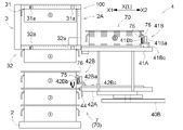
- FIG. 4 a vertical space is formed below each of them.
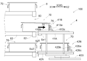
- the first transfer machine 41B sets the container 70 (container " ⁇ ") held by the first holding part 41A as the container 70 to be unloaded, and lifts the second lifting/holding part 32a (second lifting mechanism 32).
- the container 70 to be unloaded is transferred onto the container 70 (container "4") lifted by .
- the second transfer device 42B scoops up the container 70 (container "3") adjacent below the container 70 (container "4") lifted by the second lifting/holding part 32a (second lifting mechanism 32). As the target container 70, the scooping target container 70 is transferred to the second holding portion 42A.
- control device C moves the second holding part 42A to the scoop target container placed adjacently under the container 70 (container "4") lifted by the second lifting/holding part 32a. 70 (container "3") and positioned adjacent to the scooping side X2 in the transferring direction with respect to the scooping target container 70 (container "3").
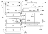
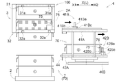
- the control device C moves the first holding part 41A and the second holding part 42A relative to the transfer elevator 40B in the transfer direction unloading side X1.
- the first holding section 41A and the second holding section 42A, and the first transfer device 41B and the second transfer device 42B approach the stacking area 2A.
- the control device C causes the second locking portion 42Bb to move relative to the second holding portion 42A toward the unloading side X1 in the transfer direction.
- the second locking portion 42Bb is arranged directly below the recess 75 of the container 70 (container "3") to be scooped.
- the second locking portion 42Bb is in the non-locking posture.
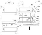
- the control device C sets the second locking portion 42Bb to the locking posture, and raises the first holding portion 41A and the second holding portion 42A as shown in FIG.
- the container 70 (container "3") to be scooped is inclined upward toward the scooping side X2 in the transfer direction.
- the engagement with the adjacent container 70 (container "2") is released.
- the first holding portion 41A and the second holding portion 42A in this way, the first holding portion 41A is positioned higher than the container 70 (container "4") lifted by the second lifting/holding portion 32a. placed above.
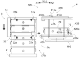
- control device C moves the lower surface of the container 70 to be unloaded (container " ⁇ ") held by the first holding unit 41A above the upper surface of the container 70 (container "4") to be unloaded. to be placed.
- the amount of upward movement of the first holding portion 41A and the second holding portion 42A at this time is equal to the vertical movement amount Mv described above.
- the control device C moves the second locking portion 42Bb to the scooping side X2 in the transfer direction with respect to the second holding portion 42A, and moves the first pressing portion 41Ba to the first holding portion 42A. It is moved to the unloading side X1 in the transfer direction with respect to the portion 41A.
- the second locking portion 42Bb draws the container 70 to be scooped (container “3”) to the scooping side X2 in the transfer direction
- the first pressing portion 41Ba causes the container 70 to be unloaded (container “ ⁇ ”). is pressed to the unloading side X1 in the transfer direction.
- the movement of the container 70 to be unloaded (container " ⁇ ") pressed by the first pressing part 41Ba is appropriately guided by the guide part 3G toward the unloading side X1 in the transfer direction.
- the control device C moves the second locking portion 42Bb to the second holding portion 42A side, and moves the restricting portion 44 to the container adjacent below the container 70 (container "3") to be scooped. 70 (container "2") from the side of the second holding portion 42A.
- the control device C presses the container 70 to be unloaded (container “ ⁇ ”) toward the unloading side X1 in the transfer direction by the first pressing portion 41Ba, and at the same time, engages the first locking portion 41Bb. Change from the locked posture to the unlocked posture.
- the container 70 to be scooped (container "3") drawn by the second locking portion 42Bb is placed on the second holding portion 42A and pressed by the first pressing portion 41Ba.
- the control device C controls the first holding unit 41A and 42 A of 2nd holding
- the container 70 to be unloaded (container " ⁇ ") pressed in the unloading direction X1 by the first pressing portion 41Ba is lifted by the second lifting/holding portion 32a.
- 70 (container "4") is closely fitted from above.
- the control device C causes the first pressing portion 41Ba to move relative to the first holding portion 41A toward the scooping side X2 in the transfer direction, and the first holding portion 41A and the second holding portion. 42A is relatively moved to the scooping side X2 in the transfer direction with respect to the transfer elevator 40B and returned to its original position.
- the first holding section 41A and the second holding section 42A, and the first transfer device 41B and the second transfer device 42B are separated from the stacking area 2A.
- the control device C lowers the first lifting/holding part 31a and the second lifting/holding part 32a, and lifts the container 70 (container "4") lifted by the second lifting/holding part 32a. is fitted into container 70 (container "2") located therebelow. Thereafter, the control device C shifts the second lifting/holding portion 32a from the holding posture to the non-holding posture. Then, the control device C further lowers the first lifting/holding part 31a and the second lifting/holding part 32a, and moves the container 70 (container "5") lifted by the first lifting/holding part 31a to the position below it. 70 (container " ⁇ "). Thereafter, the control device C shifts the first lifting/holding portion 31a from the holding posture to the non-holding posture.
- the parallel operation of scooping up and unloading the containers 70 from the stacking area 2A in parallel is completed.
- the parallel operation is performed by the control device C controlling each functional unit of the transport vehicle 100 as described above.
- the transfer device 4 is configured to perform a replacement operation for replacing the container 70 with respect to a specific shelf 80 . Specifically, in the replacement operation, the transfer device 4 scoops the container 70 from the shelf 80 in which the container 70 is stored, and unloads the other container 70 onto the empty shelf 80 as a result. As a result, while the containers 70 are replaced on each shelf 80, the state in which the containers 70 are always accommodated on the shelf 80 can be maintained. Therefore, in the entire container shelf 8, the ratio of the shelf portion 80 in which the container 70 is stored is higher than the ratio of the empty shelf portion 80 in which the container 70 is not stored. can be maintained at a high level.
- the transfer device 4 exchanges the containers 70 while one of the first holding portion 41A and the second holding portion 42A holds the container 70 .
- the transfer device 4 targets the shelf 80 in which the container 70 is accommodated, and removes the container 70 from the shelf 80 from the first holding part 41A and the second holding part 42A that does not hold the container 70 .
- a scooping operation is performed to transfer the container 70 to the first holding unit 41A or the second holding unit 42A, and the container is moved from the first holding unit 41A or the second holding unit 42A, which holds the container 70 in advance, to the shelf unit 80 emptied by the scooping operation. Unloading operation for transferring 70 is performed.
- the transfer device 4 exchanges the containers 70 while the first holding unit 41A does not hold the containers 70 and the second holding unit 42A holds the containers 70 . Then, the transfer device 4 performs a scooping operation to transfer the container 70 from the shelf portion 80 to the first holding portion 41A, and then an unloading operation to transfer the container 70 from the second holding portion 42A to the shelf portion 80. I do.
- FIG. 35 to 42 the first locking portion 41Bb or the second locking portion 42Bb in the locking posture are shown in gray, and the first locking portion 41Bb or the second locking portion 42Bb in the non-locking posture are shown in gray. Shown in white.
- the control device C moves the first holding part 41A and the second holding part 42A relative to the transfer elevator 40B in the transfer direction unloading side X1.
- the first holding section 41A and the second holding section 42A, and the first transfer device 41B and the second transfer device 42B approach the shelf section 80 .
- the control device C causes the first locking portion 41Bb to move relative to the first holding portion 41A toward the unloading side X1 in the transfer direction.
- the first locking portion 41Bb is arranged directly below the recess 75 in the container 70 .
- the first locking portion 41Bb is in the non-locking posture.
- the control device C puts the first locking portion 41Bb in the locking posture with the first locking portion 41Bb arranged directly below the recess 75 .
- the first locking portion 41Bb is inserted into the concave portion 75, and the first locking portion 41Bb is arranged to face the locking wall 76 in the transfer direction unloading side X1.
- the control device C moves the first locking portion 41Bb in the locking posture to the scooping side X2 in the transfer direction with respect to the first holding portion 41A while contacting the locking wall 76. As shown in FIG. move relative to As a result, the first locking portion 41Bb pulls the container 70 stored in the shelf portion 80 into the first holding portion 41A.
- the shelf section 80 from which the container 70 has been taken out becomes empty, and the first holding section 41A and the second holding section 42A hold the container 70 respectively.
- the control device C raises the first holding portion 41A and the second holding portion 42A while maintaining the positions of the first holding portion 41A and the second holding portion 42A in the transfer direction X. Then, the vertical position of the second holding portion 42A is aligned with the shelf portion 80 emptied by the scooping operation. At this time, the position of the traveling body 1 and the orientation of the transfer device 4 by the turning device 5 are also maintained.
- the storage container detection sensor Se2 attached to the second holding portion 42A detects whether or not the container 70 is stored in the shelf portion 80 where the scooping operation has been performed. When it is confirmed by the detection result of the storage container detection sensor Se2 that the container 70 is not stored on the shelf 80, the container 70 held by the second holding unit 42A is detected by the second transfer device 42B. Transfer to the shelf section 80 is started.
- the control device C moves the second pressing portion 42Ba relative to the second holding portion 42A in the transfer direction unloading side X1, and directs the container 70 toward the transfer direction unloading side X1. and press.
- the container 70 to be unloaded held by the second holding section 42A is moved from the second holding section 42A to the shelf section 80 .
- the second pressing portion 42Ba presses the container 70 toward the transfer direction unloading side X1 while being in contact with the locking wall 76 of the container 70 from the transfer direction scooping side X2.
- control device C controls the second engaging member that moves to the transfer direction unloading side X1 together with the second pressing portion 42Ba while the unloading target container 70 is moving toward the transfer direction unloading side X1.
- the stopping portion 42Bb is changed from the locking posture to the non-locking posture.
- the control device C moves the second pressing portion 42Ba toward the scooping side X2 in the transfer direction with respect to the second holding portion 42A.
- the first holding portion 41A and the second holding portion 42A are moved relative to the transfer lifting body 40B in the transfer direction scooping side X2 and returned to their original positions.
- the first holding section 41A and the second holding section 42A, and the first transfer device 41B and the second transfer device 42B are separated from the shelf section 80 .
- the replacement operation of the container 70 with respect to the shelf 80 is performed.
- the replacement operation is performed by the control device C controlling each functional unit of the transport vehicle 100 as described above.
- the first transfer machine 41B does not unload the container 70 . Therefore, the storage container detection sensor Se2 for detecting whether or not there is a container 70 on the shelf 80, which is the transfer destination when the unloading operation is performed, is connected to the first transfer device 41B and the first holding unit that do not perform the unloading operation. It may not be provided in the pair with 41A. However, this is not intended to exclude the provision of the storage container detection sensor Se2 in the set of the first transfer device 41B and the first holding section 41A.
- the height of N stages of the container 70 is taken into consideration for the vertical interval 3H between the first lifting/holding portion 31a and the second lifting/holding portion 32a, and "N" is "2". ” was set as an example. However, without being limited to such an example, "N" may be set to an integer of 2 or more.
- the vertical distance 4H between the first holding portion 41A and the second holding portion 42A takes into consideration the height of two stages of the container 70 (70H ⁇ 2). explained.
- the vertical direction of the first holding portion 41A and the second holding portion 42A is not limited to such an example, and the height of N stages of the container 70 (N is an integer equal to or greater than 2) is considered.
- interval 4H may be set.
- the transport vehicle 100 is provided with the turning device 5 that turns the transfer device 4 around the axis along the vertical direction, but the turning device 5 is an essential component. is not. Therefore, the transport vehicle 100 does not have to include the turning device 5 .
- the transfer direction X is a direction fixed with respect to the carrier 100 .
- the reference position detection sensor Se1 is provided in the set of the first holding section 41A and the first transfer device 41B, and the storage container detection sensor Se2 is provided in the set of the second holding section 42A and the second transfer device.
- An example provided in the set of the loading machine 42B has been described.
- the set provided with the reference position detection sensor Se1 and the set provided with the storage container detection sensor Se2 may be reversed.
- both the reference position detection sensor Se1 and the storage container detection sensor Se2 may be provided in one set.
- the reference position detection sensor Se1 may be provided in one of the sets, and the storage container detection sensor Se2 may be provided in both sets.
- the first holding drive unit 41MA that moves the first holding unit 41A along the transfer direction X and the second holding unit that moves the second holding unit 42A along the transfer direction X An example in which the drive unit 42MA and the drive unit 42MA are configured by a common drive source has been described. However, the first holding drive section 41MA and the second holding drive section 42MA may be configured to be driven by independent drive sources.
- the regulating portion 44 is attached to the second holding portion 42A, and when the second transfer device 42B performs the scooping operation of the container 70, it is adjacent below the container 70 to be scooped.
- the restriction portion 44 may also be provided in the first holding portion 41A.
- the regulating portion 44 provided in the first holding portion 41A allows, for example, the first lifting mechanism 31 to lift the plurality of containers 70 in a stacked state and the first transfer device 41B to scoop up the uppermost container 70.
- the uppermost container 70 is arranged so as to face the container 70 adjacent to the uppermost container 70 on the side of the first holding portion 41A.
- the guide portion 3G may be provided in at least one of the first lifting mechanism and the second lifting mechanism.
- the guide portion 3G may be provided in the first lifting mechanism 31 and not provided in the second lifting mechanism 32 .
- This configuration is suitable for transferring (stacking) another container 70 onto the container 70 lifted by the first lifting mechanism 31 .
- the guide portion 3G may be provided on both the first lifting mechanism 31 and the second lifting mechanism 32.
- FIG. In this configuration another container 70 is transferred (stacked) onto the container 70 lifted by the first lifting mechanism 31 and onto the container 70 lifted by the second lifting mechanism 32. It is suitable for
- the first transfer device 41B is configured to move relative to the first holding section 41A in the transfer direction X
- the second transfer device 42B is configured to move relative to the second holding section 41A.
- An example configured to move in the transfer direction X relative to 42A has been described.
- the first transfer device 41B and the first holding unit 41A are configured to integrally move in the transfer direction X
- the second transfer device 42B and the first 2 holding part 42A may be configured to move in the transfer direction X integrally.
- the lifting rib portion 73 lifted by the lifting device 3 is formed on the upper portion of the peripheral wall portion 72 .
- the lifting rib portion 73 may be formed anywhere on the peripheral wall portion 72, and may be formed, for example, in the center portion or the lower portion in the vertical direction.
- the portion of the container 70 to be lifted by the lifting device 3 is not limited to the lifting rib portion 73 .
- the lifting device 3 may use any portion of the container 70 as the portion to be lifted.
- the lifting device 3 may be configured to lift the container 70 by pinching the uneven portion of the peripheral wall portion 72 of the container 70 .
- the transfer of the container 70 by the first transfer device 41B and the transfer of the container 70 by the second transfer device 42B have been described with specific examples.
- the container 70 may be transferred using only the first transfer device 41B, and the container 70 may be transferred using only the second transfer device 42B.
- the first transfer device 41B and the second transfer device 42B Of these only the lower second transfer device 42B can be used.
- the second transfer device 42B scoops up the container 70 stored on the bottom shelf 80 of the container shelf 8, and moves the container 70 to the stacking area 2A (first lifting mechanism). 31).
- the second transfer machine 42B scoops up the other containers 70 in the stacking area 2A (containers 70 placed below the containers 70 lifted by the second lifting mechanism 32), and The other container 70 is unloaded onto the lower shelf 80 .
- the first transfer device 41B and the second Of the two transfer devices 42B only the first transfer device 41B arranged on the upper side can be used.
- the first transfer device 41B scoops up the container 70 stored on the uppermost shelf 80 of the container shelf 8 and moves the container 70 to the stacking area 2A (first lifting mechanism). 31).
- the first transfer machine 41B scoops up the other containers 70 in the stacking area 2A (containers 70 placed below the containers 70 lifted by the second lifting mechanism 32), and The other container 70 is unloaded onto the upper shelf 80 .
- the traveling body 1 may be configured to travel on rails installed near the floor or ceiling. That is, the transport vehicle 100 may be configured as, for example, a ground transport vehicle that runs along rails set on the floor or an overhead transport vehicle that runs along rails suspended from the ceiling. Further, the carrier 100 may be configured as a stacker crane, for example.
- a transport vehicle for transporting containers configured to be vertically stackable, a running body that runs; a container group supporting portion mounted on the traveling body and supporting a plurality of the containers as a stacked container group within a prescribed stacking area; a lifting device that is mounted on the traveling body and lifts the container of the container group supported by the container group supporting portion; a transfer device mounted on the traveling body for transferring the container,
- the transfer device includes a first holding section that holds the container, a second holding section that is arranged below the first holding section and holds the container, the first holding section and the stacking area. and a second transfer machine for transferring the container between the second holding section and the stacking area.
- the lifting device includes a first lifting mechanism that lifts the container at an arbitrary height among the containers stacked in the stacking area with respect to the container adjacent below the container; a second lifting mechanism for lifting the container below the container lifted by the lifting mechanism relative to the container adjacent below the container.
- the container can be transferred to the stacking area by the first transfer device, and the container can be transferred to the stacking area by the second transfer device.
- vertical spaces can be provided below the containers lifted by the first lifting mechanism and below the containers lifted by the second lifting mechanism. Therefore, by utilizing the two spaces provided in this manner, the transfer of the containers by the first transfer device and the transfer of the containers by the second transfer device to the stacked container group are performed in parallel. be able to.
- the first lifting mechanism includes a first lifting and holding part that holds the container
- the second lifting mechanism includes a second lifting and holding part arranged below the first lifting and holding part to hold the container
- the vertical interval between the first lifting and holding part and the second lifting and holding part is a height of N stages (N is an integer equal to or greater than 2) of the container, and the transfer by the second transfer device is performed. It is preferable that the height is set according to the height obtained by adding the amount of vertical movement of the container to be transferred during operation.
- the first transfer machine moves up and down to transfer the second transfer machine.
- the container can be appropriately transferred between the first lifting/holding part and the second lifting/holding part in the vertical direction without being affected by the operation. Thereby, the container can be appropriately stacked on the container lifted and held by the second lifting and holding part.
- the vertical interval between the first holding portion and the second holding portion is set to the height of two stages of the container, and the object to be transferred during the transfer operation by the second transfer device is It is preferable that the distance is equal to or greater than the height of the vertical movement of the container.
- the adjacent container to be scooped can be properly scooped so that the adjacent container to be scooped does not interfere with the lifted container.
- another container is unloaded by the second transfer device into the space formed below the lifted container by a transfer operation involving vertical movement, the other container to be unloaded does not interfere with the lifted container. can be properly wholesaled.
- the second holding section is arranged at a height for the second transfer device to transfer the container adjacent under the container lifted by the second lifting mechanism to the second holding section.
- the container held by the first holding unit at a height for transferring onto the container lifted by the second lifting mechanism. It is preferable that the vertical interval between the first holding portion and the second holding portion is set so that the portions are arranged.
- the second transfer device transfers the container from the stacking area to the second holding section
- the first transfer device transfers the container from the first holding section to the stacking area
- the traveling body is configured to travel along the container shelf having a plurality of shelves for storing the container in the vertical direction, With the movement direction of the container transferred by the transfer device as the transfer direction, A first posture in which the transfer direction is oriented toward the stacking region and a second posture in which the transfer direction is oriented toward the container shelf by turning the transfer device around the axis along the vertical direction. a turning device for changing the orientation of the transfer device, The first transfer device transfers the container between the first holding unit and the stacking area in the state of the first posture, and the first holding unit in the state of the second posture. and the container is transferred between the shelf, The second transfer machine transfers the container between the second holding part and the stacking area in the state of the first posture, and transfers the container to the second holding part in the state of the second posture. and the shelf portion.
- the container can be transferred to the shelf portion of the container shelf and the container can be transferred to the stacking area by the transfer device. Further, in the second posture in which the transfer device faces the transfer direction toward the container shelf, the transfer operation by the first transfer device and the transfer operation by the second transfer device to the container shelf can be performed in parallel. can.
- the transfer device includes a reference position detection sensor that detects a reference position for storing the container on the shelf, and a storage container detection sensor that detects the container stored on the shelf,
- the reference position detection sensor is provided in one of the set of the first holding unit and the first transfer device and the set of the second holding unit and the second transfer device
- the storage container detection sensor is the other of the set of the first holding section and the first transfer device and the set of the second holding section and the second transfer device, in which the reference position detection sensor is not provided. is preferably provided in the set of
- the container can be transferred at an appropriate transfer position with respect to the shelf.
- the storage container detection sensor it is possible to detect the containers already stored in the shelf, so that the operation of further storing the container in such a shelf can be prevented.
- the reference position detection sensor is provided in one of the set of the first holding section and the first transfer device and the set of the second holding section and the second transfer device, and the storage container detection sensor is provided at the reference position Since the detection sensor is provided in the other set, which is not provided with the detection sensor, the total number of sensors installed in the transfer device can be reduced.
- the transfer device includes a first holding drive section that moves the first holding section along the transfer direction, a second holding drive section that moves the second holding section along the transfer direction, is preferably provided.
- the first holding part and the second holding part can be brought closer to the stacking area, and in this state, the container can be transferred by the transfer device. Therefore, the container can be stably transferred.
- the second transfer device performs a scooping operation of transferring the scooped target container to the second holding unit, with the container adjacent to the bottom of the container lifted by the second lifting mechanism as the scooped target container. is configured to do
- the transfer device is arranged to face the container adjacent below the scooping target container on the second holding part side, It is preferable to provide a regulating portion for regulating movement of the container adjacent to and below the scooping target container toward the second holding portion.
- the scooping target container moving toward the second holding portion interferes with the adjacent container, which is the container adjacent below, and the adjacent container is forced to the second holding portion side. It is possible to prevent the adjacent container and the plurality of containers stacked below the adjacent container from falling toward the second holding portion when the container is subjected to a load.
- the second transfer device With the movement direction of the container transferred by the transfer device as the transfer direction, the second transfer device includes a second locking portion that is locked to the container, The restricting portion is attached to the second holding portion and arranged below the second locking portion, It is preferable that the second engaging portion and the restricting portion are configured to be relatively movable along the transfer direction.
- the restricting portion when the scooping operation is performed, the restricting portion is held in a position facing the container from the second holding portion side while moving the second locking portion toward the second holding portion side. be able to. Therefore, while appropriately scooping the scooping target container, it is possible to appropriately prevent the containers adjacent to and below the scooping target container and the plurality of containers stacked below the scooping target container from falling toward the second holding portion side. .
- At least one of the first lifting mechanism and the second lifting mechanism is provided with a guide portion that guides the container transferred by the transfer device.
- the container transferred to the stacking area by the transfer device can be appropriately guided by the guide section.
- the technology according to the present disclosure can be used for a transport vehicle that transports containers that can be stacked vertically.
Landscapes
- Engineering & Computer Science (AREA)
- Transportation (AREA)
- Structural Engineering (AREA)
- Mechanical Engineering (AREA)
- Civil Engineering (AREA)
- Life Sciences & Earth Sciences (AREA)
- Geology (AREA)
- Warehouses Or Storage Devices (AREA)
- Stacking Of Articles And Auxiliary Devices (AREA)
- Load-Engaging Elements For Cranes (AREA)
Priority Applications (3)
| Application Number | Priority Date | Filing Date | Title |
|---|---|---|---|
| CN202280024606.1A CN117062762A (zh) | 2021-03-26 | 2022-02-04 | 输送车 |
| KR1020237034933A KR20230161461A (ko) | 2021-03-26 | 2022-02-04 | 반송차 |
| EP22774705.2A EP4299475A1 (en) | 2021-03-26 | 2022-02-04 | Transport vehicle |
Applications Claiming Priority (2)
| Application Number | Priority Date | Filing Date | Title |
|---|---|---|---|
| JP2021-053476 | 2021-03-26 | ||
| JP2021053476A JP7294363B2 (ja) | 2021-03-26 | 2021-03-26 | 搬送車 |
Publications (1)
| Publication Number | Publication Date |
|---|---|
| WO2022201904A1 true WO2022201904A1 (ja) | 2022-09-29 |
Family
ID=83396902
Family Applications (1)
| Application Number | Title | Priority Date | Filing Date |
|---|---|---|---|
| PCT/JP2022/004508 WO2022201904A1 (ja) | 2021-03-26 | 2022-02-04 | 搬送車(transport vehicle) |
Country Status (6)
| Country | Link |
|---|---|
| EP (1) | EP4299475A1 (ko) |
| JP (2) | JP7294363B2 (ko) |
| KR (1) | KR20230161461A (ko) |
| CN (1) | CN117062762A (ko) |
| TW (1) | TW202237511A (ko) |
| WO (1) | WO2022201904A1 (ko) |
Families Citing this family (1)
| Publication number | Priority date | Publication date | Assignee | Title |
|---|---|---|---|---|
| JP2024070652A (ja) * | 2022-11-11 | 2024-05-23 | 株式会社ダイフク | 搬送装置 |
Citations (3)
| Publication number | Priority date | Publication date | Assignee | Title |
|---|---|---|---|---|
| JP2006264951A (ja) * | 2005-03-25 | 2006-10-05 | Seibu Electric & Mach Co Ltd | 容器の段積み段ばらし装置 |
| JP2018154479A (ja) * | 2017-03-21 | 2018-10-04 | トーヨーカネツソリューションズ株式会社 | 立体自動倉庫 |
| JP2019018983A (ja) | 2017-07-20 | 2019-02-07 | 株式会社ダイフク | 搬送車及び搬送設備 |
-
2021
- 2021-03-26 JP JP2021053476A patent/JP7294363B2/ja active Active
-
2022
- 2022-02-04 WO PCT/JP2022/004508 patent/WO2022201904A1/ja active Application Filing
- 2022-02-04 EP EP22774705.2A patent/EP4299475A1/en active Pending
- 2022-02-04 CN CN202280024606.1A patent/CN117062762A/zh active Pending
- 2022-02-04 KR KR1020237034933A patent/KR20230161461A/ko unknown
- 2022-02-10 TW TW111104937A patent/TW202237511A/zh unknown
-
2023
- 2023-05-29 JP JP2023088021A patent/JP2023101643A/ja active Pending
Patent Citations (3)
| Publication number | Priority date | Publication date | Assignee | Title |
|---|---|---|---|---|
| JP2006264951A (ja) * | 2005-03-25 | 2006-10-05 | Seibu Electric & Mach Co Ltd | 容器の段積み段ばらし装置 |
| JP2018154479A (ja) * | 2017-03-21 | 2018-10-04 | トーヨーカネツソリューションズ株式会社 | 立体自動倉庫 |
| JP2019018983A (ja) | 2017-07-20 | 2019-02-07 | 株式会社ダイフク | 搬送車及び搬送設備 |
Also Published As
| Publication number | Publication date |
|---|---|
| JP2023101643A (ja) | 2023-07-21 |
| EP4299475A1 (en) | 2024-01-03 |
| JP7294363B2 (ja) | 2023-06-20 |
| TW202237511A (zh) | 2022-10-01 |
| CN117062762A (zh) | 2023-11-14 |
| KR20230161461A (ko) | 2023-11-27 |
| JP2022150741A (ja) | 2022-10-07 |
Similar Documents
| Publication | Publication Date | Title |
|---|---|---|
| KR102596987B1 (ko) | 반송차 및 반송 설비 | |
| KR102279602B1 (ko) | 물품 반송 설비 | |
| CN110831873B (zh) | 搬运系统以及搬运方法 | |
| KR20200027996A (ko) | 천장 반송차, 반송 시스템, 및 천장 반송차의 제어 방법 | |
| JP2008120586A (ja) | 物品収納装置 | |
| JP2023101643A (ja) | 搬送車 | |
| KR20170057847A (ko) | 물품 반송 설비 | |
| JP2023133357A (ja) | 搬送車 | |
| JP7310854B2 (ja) | 搬送装置 | |
| JP6593270B2 (ja) | 物品搬送設備 | |
| JP2022175430A (ja) | 移載装置 | |
| WO2022149305A1 (ja) | 天井保管システム | |
| US20230142253A1 (en) | Container handling vehicle comprising a container carrying position, associated system and methods | |
| JPH07215665A (ja) | パレタイザーおよび空パレット供給装置 | |
| JP7322917B2 (ja) | 搬送車 | |
| JP4618511B2 (ja) | 自動倉庫 | |
| WO2024100952A1 (ja) | 搬送装置(transport apparatus) | |
| KR20200041795A (ko) | 수용 시스템 | |
| JP7044182B2 (ja) | 搬送車 | |
| JP7318676B2 (ja) | 搬送装置 | |
| WO2024070334A1 (ja) | 搬送車(transport vehicle) | |
| JP2024058394A (ja) | 搬送システム | |
| JP2022178482A (ja) | 物品搬送設備 | |
| JPH0582913U (ja) | 水平伸縮移載装置を具えたホイスト型キャリヤ |
Legal Events
| Date | Code | Title | Description |
|---|---|---|---|
| 121 | Ep: the epo has been informed by wipo that ep was designated in this application |
Ref document number: 22774705 Country of ref document: EP Kind code of ref document: A1 |
|
| WWE | Wipo information: entry into national phase |
Ref document number: 202280024606.1 Country of ref document: CN |
|
| WWE | Wipo information: entry into national phase |
Ref document number: 2022774705 Country of ref document: EP |
|
| ENP | Entry into the national phase |
Ref document number: 2022774705 Country of ref document: EP Effective date: 20230927 |
|
| ENP | Entry into the national phase |
Ref document number: 20237034933 Country of ref document: KR Kind code of ref document: A |
|
| WWE | Wipo information: entry into national phase |
Ref document number: 1020237034933 Country of ref document: KR |
|
| NENP | Non-entry into the national phase |
Ref country code: DE |