WO2022195871A1 - 電磁波ノイズ抑制シートおよびその製造方法 - Google Patents
電磁波ノイズ抑制シートおよびその製造方法 Download PDFInfo
- Publication number
- WO2022195871A1 WO2022195871A1 PCT/JP2021/011477 JP2021011477W WO2022195871A1 WO 2022195871 A1 WO2022195871 A1 WO 2022195871A1 JP 2021011477 W JP2021011477 W JP 2021011477W WO 2022195871 A1 WO2022195871 A1 WO 2022195871A1
- Authority
- WO
- WIPO (PCT)
- Prior art keywords
- noise suppression
- inorganic filler
- layer
- cnt
- dispersion
- Prior art date
- Legal status (The legal status is an assumption and is not a legal conclusion. Google has not performed a legal analysis and makes no representation as to the accuracy of the status listed.)
- Ceased
Links
Images






Classifications
-
- H—ELECTRICITY
- H05—ELECTRIC TECHNIQUES NOT OTHERWISE PROVIDED FOR
- H05K—PRINTED CIRCUITS; CASINGS OR CONSTRUCTIONAL DETAILS OF ELECTRIC APPARATUS; MANUFACTURE OF ASSEMBLAGES OF ELECTRICAL COMPONENTS
- H05K9/00—Screening of apparatus or components against electric or magnetic fields
- H05K9/0073—Shielding materials
- H05K9/0081—Electromagnetic shielding materials, e.g. EMI, RFI shielding
- H05K9/009—Electromagnetic shielding materials, e.g. EMI, RFI shielding comprising electro-conductive fibres, e.g. metal fibres, carbon fibres, metallised textile fibres, electro-conductive mesh, woven, non-woven mat, fleece, cross-linked
-
- H—ELECTRICITY
- H05—ELECTRIC TECHNIQUES NOT OTHERWISE PROVIDED FOR
- H05K—PRINTED CIRCUITS; CASINGS OR CONSTRUCTIONAL DETAILS OF ELECTRIC APPARATUS; MANUFACTURE OF ASSEMBLAGES OF ELECTRICAL COMPONENTS
- H05K9/00—Screening of apparatus or components against electric or magnetic fields
- H05K9/0073—Shielding materials
- H05K9/0081—Electromagnetic shielding materials, e.g. EMI, RFI shielding
-
- C—CHEMISTRY; METALLURGY
- C08—ORGANIC MACROMOLECULAR COMPOUNDS; THEIR PREPARATION OR CHEMICAL WORKING-UP; COMPOSITIONS BASED THEREON
- C08J—WORKING-UP; GENERAL PROCESSES OF COMPOUNDING; AFTER-TREATMENT NOT COVERED BY SUBCLASSES C08B, C08C, C08F, C08G or C08H
- C08J5/00—Manufacture of articles or shaped materials containing macromolecular substances
- C08J5/18—Manufacture of films or sheets
-
- C—CHEMISTRY; METALLURGY
- C08—ORGANIC MACROMOLECULAR COMPOUNDS; THEIR PREPARATION OR CHEMICAL WORKING-UP; COMPOSITIONS BASED THEREON
- C08J—WORKING-UP; GENERAL PROCESSES OF COMPOUNDING; AFTER-TREATMENT NOT COVERED BY SUBCLASSES C08B, C08C, C08F, C08G or C08H
- C08J7/00—Chemical treatment or coating of shaped articles made of macromolecular substances
- C08J7/04—Coating
- C08J7/0427—Coating with only one layer of a composition containing a polymer binder
-
- C—CHEMISTRY; METALLURGY
- C08—ORGANIC MACROMOLECULAR COMPOUNDS; THEIR PREPARATION OR CHEMICAL WORKING-UP; COMPOSITIONS BASED THEREON
- C08K—Use of inorganic or non-macromolecular organic substances as compounding ingredients
- C08K3/00—Use of inorganic substances as compounding ingredients
- C08K3/02—Elements
- C08K3/04—Carbon
-
- C—CHEMISTRY; METALLURGY
- C08—ORGANIC MACROMOLECULAR COMPOUNDS; THEIR PREPARATION OR CHEMICAL WORKING-UP; COMPOSITIONS BASED THEREON
- C08K—Use of inorganic or non-macromolecular organic substances as compounding ingredients
- C08K3/00—Use of inorganic substances as compounding ingredients
- C08K3/02—Elements
- C08K3/04—Carbon
- C08K3/041—Carbon nanotubes
-
- C—CHEMISTRY; METALLURGY
- C08—ORGANIC MACROMOLECULAR COMPOUNDS; THEIR PREPARATION OR CHEMICAL WORKING-UP; COMPOSITIONS BASED THEREON
- C08K—Use of inorganic or non-macromolecular organic substances as compounding ingredients
- C08K3/00—Use of inorganic substances as compounding ingredients
- C08K3/02—Elements
- C08K3/04—Carbon
- C08K3/042—Graphene or derivatives, e.g. graphene oxides
-
- C—CHEMISTRY; METALLURGY
- C08—ORGANIC MACROMOLECULAR COMPOUNDS; THEIR PREPARATION OR CHEMICAL WORKING-UP; COMPOSITIONS BASED THEREON
- C08K—Use of inorganic or non-macromolecular organic substances as compounding ingredients
- C08K3/00—Use of inorganic substances as compounding ingredients
- C08K3/34—Silicon-containing compounds
-
- C—CHEMISTRY; METALLURGY
- C08—ORGANIC MACROMOLECULAR COMPOUNDS; THEIR PREPARATION OR CHEMICAL WORKING-UP; COMPOSITIONS BASED THEREON
- C08K—Use of inorganic or non-macromolecular organic substances as compounding ingredients
- C08K3/00—Use of inorganic substances as compounding ingredients
- C08K3/34—Silicon-containing compounds
- C08K3/346—Clay
-
- C—CHEMISTRY; METALLURGY
- C08—ORGANIC MACROMOLECULAR COMPOUNDS; THEIR PREPARATION OR CHEMICAL WORKING-UP; COMPOSITIONS BASED THEREON
- C08L—COMPOSITIONS OF MACROMOLECULAR COMPOUNDS
- C08L1/00—Compositions of cellulose, modified cellulose or cellulose derivatives
- C08L1/08—Cellulose derivatives
- C08L1/26—Cellulose ethers
- C08L1/28—Alkyl ethers
- C08L1/286—Alkyl ethers substituted with acid radicals, e.g. carboxymethyl cellulose [CMC]
-
- H—ELECTRICITY
- H05—ELECTRIC TECHNIQUES NOT OTHERWISE PROVIDED FOR
- H05K—PRINTED CIRCUITS; CASINGS OR CONSTRUCTIONAL DETAILS OF ELECTRIC APPARATUS; MANUFACTURE OF ASSEMBLAGES OF ELECTRICAL COMPONENTS
- H05K7/00—Constructional details common to different types of electric apparatus
- H05K7/20—Modifications to facilitate cooling, ventilating, or heating
- H05K7/2039—Modifications to facilitate cooling, ventilating, or heating characterised by the heat transfer by conduction from the heat generating element to a dissipating body
- H05K7/20436—Inner thermal coupling elements in heat dissipating housings, e.g. protrusions or depressions integrally formed in the housing
- H05K7/20445—Inner thermal coupling elements in heat dissipating housings, e.g. protrusions or depressions integrally formed in the housing the coupling element being an additional piece, e.g. thermal standoff
- H05K7/20472—Sheet interfaces
- H05K7/20481—Sheet interfaces characterised by the material composition exhibiting specific thermal properties
-
- C—CHEMISTRY; METALLURGY
- C08—ORGANIC MACROMOLECULAR COMPOUNDS; THEIR PREPARATION OR CHEMICAL WORKING-UP; COMPOSITIONS BASED THEREON
- C08J—WORKING-UP; GENERAL PROCESSES OF COMPOUNDING; AFTER-TREATMENT NOT COVERED BY SUBCLASSES C08B, C08C, C08F, C08G or C08H
- C08J2301/00—Characterised by the use of cellulose, modified cellulose or cellulose derivatives
- C08J2301/08—Cellulose derivatives
- C08J2301/26—Cellulose ethers
- C08J2301/28—Alkyl ethers
Definitions
- the present invention relates to an electromagnetic noise suppression sheet and a manufacturing method thereof.
- a carbon nanotube has a structure that resembles a flat, flat graphene sheet rolled into a cylinder. Since carbon nanotubes have such a unique structure, they have various properties and are expected to be applied in a wide range of fields.
- Patent Literature 1 describes an electromagnetic wave suppressing sheet coated with multi-walled carbon nanotubes to a base material in an amount of 1 g/cm 2 or more.
- the electromagnetic wave suppression sheet as described above is used, for example, by being attached to an electronic device.
- Electronic devices tend to trap heat. Therefore, it is required to have high thermal conductivity as well as electromagnetic noise suppression performance. If the thermal conductivity is high, the heat of the electronic device can be efficiently dissipated.
- carbon nanotubes such as those described above are expensive, cost reduction can be achieved if part of the carbon nanotubes can be replaced with other inorganic materials while ensuring electromagnetic noise suppression performance.
- One aspect of the electromagnetic noise suppression sheet according to the present invention is including a first layer comprising carbon nanotubes, an inorganic filler, and carboxymethyl cellulose;
- the inorganic filler is at least one selected from the group consisting of graphite, carbon black, and inorganic pigments,
- the ratio of the mass of the inorganic filler to the mass of the carbon nanotube is 1/4 or more and 2 or less.
- the inorganic filler may be the graphite.
- the inorganic filler may be the inorganic pigment.
- the inorganic pigment may be kaolin.
- the ratio may be 1 or less.
- the ratio may be 1 or more.
- a second layer provided with the first layer may be included.
- One aspect of the method for manufacturing an electromagnetic noise suppression sheet according to the present invention is A step of preparing a dispersion containing carbon nanotubes, an inorganic filler, carboxymethyl cellulose, and water; drying the dispersion to form a first layer; including
- the inorganic filler is at least one selected from the group consisting of graphite, carbon black, and inorganic pigments,
- the ratio of the mass of the inorganic filler to the mass of the carbon nanotube is 1/4 or more and 2 or less.
- the inorganic filler may be the graphite.
- the inorganic filler may be the inorganic pigment.
- the inorganic pigment may be kaolin.
- a step of applying the dispersion to the second layer may be included before the step of forming the first layer.
- An electromagnetic noise suppression sheet includes a first layer containing carbon nanotubes, an inorganic filler, and carboxymethyl cellulose, and the inorganic filler is at least one selected from the group consisting of graphite, carbon black, and inorganic pigments. Since the ratio of the mass of the inorganic filler to the mass of the carbon nanotubes is 1/4 or more and 2 or less, the electromagnetic wave noise suppression performance and thermal conductivity are high, and the cost is low.
- FIG. 1 is a cross-sectional view schematically showing an electromagnetic noise suppression sheet according to this embodiment.
- FIG. 2 is a cross-sectional view schematically showing the electromagnetic noise suppression sheet according to this embodiment.
- FIG. 3 is a cross-sectional view schematically showing an electromagnetic noise suppression sheet according to this embodiment.
- FIG. 4 is a flow chart for explaining the method for manufacturing the electromagnetic noise suppression sheet according to this embodiment.
- FIG. 5 is a flow chart for explaining the method for manufacturing the electromagnetic noise suppression sheet according to this embodiment.
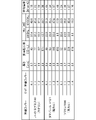
- FIG. 6 is a table showing the transmission attenuation factor of coated paper when carbon black or graphite is used as the inorganic filler.
- FIG. 11 is a table showing the transmission attenuation rate of coated paper when an inorganic pigment is used as the inorganic filler.
- FIG. 1 is a cross-sectional view schematically showing an electromagnetic noise suppression sheet 100 according to this embodiment.
- the electromagnetic noise suppression sheet 100 has a sheet shape in which the length in the in-plane direction (the direction perpendicular to the thickness direction) is sufficiently long with respect to the thickness direction.
- the planar shape of the electromagnetic noise suppression sheet 100 is not particularly limited, it is rectangular, for example.
- the electromagnetic noise suppression sheet 100 includes, for example, a coating layer 10 as a first layer, a support layer 20 as a second layer, an adhesive layer 30, and a release layer 40, as shown in FIG.
- a coating layer 10 as a first layer
- a support layer 20 as a second layer
- an adhesive layer 30, and a release layer 40 as shown in FIG.
- each member will be described in order.
- Coating layer 1.1.1.1. Physical Properties The coating layer 10 is provided on the support layer 20 .
- the coating layer 10 is a layer coated on the support layer 20 .
- the surface resistivity of the coating layer 10 is, for example, 400 ⁇ / ⁇ or less, preferably 300 ⁇ / ⁇ or less, and more preferably 200 ⁇ / ⁇ or less. If the surface resistivity of the coating layer 10 is 400 ⁇ / ⁇ or less, the electromagnetic noise suppression performance can be enhanced.
- the surface resistivity of the coating layer 10 can be measured according to "JIS K 7194".
- the thickness of the coating layer 10 is, for example, 1.0 ⁇ m or more and 300 ⁇ m or less, preferably 2.0 ⁇ m or more and 250 ⁇ m or less, and more preferably 3.0 ⁇ m or more and 200 ⁇ m or less. If the thickness of the coating layer 10 is 1.0 ⁇ m or more, the surface resistivity of the coating layer 10 can be lowered. If the thickness of the coating layer 10 is 300 ⁇ m or less, the possibility of cracks occurring in the coating layer 10 can be reduced. The thickness of the coating layer 10 can be measured by SEM (Scanning Electron Microscope).
- the in-plane thermal conductivity of the coating layer 10 is, for example, 1.10 W/m ⁇ K or more, preferably 1.20 W/m ⁇ K or more, and more preferably 1.50 W/m ⁇ K. That's it.
- the “thermal conductivity in the in-plane direction of the coating layer 10” is the thermal conductivity in the direction orthogonal to the thickness direction of the coating layer 10 (the stacking direction of the coating layer 10 and the support layer 20).
- thermal conductivity in the in-plane direction of the coating layer 10 is also simply referred to as "thermal conductivity of the coating layer 10". If the thermal conductivity of the coating layer 10 is 1.10 W/m ⁇ K or more, the thermal conductivity of the electromagnetic noise suppression sheet 100 can be increased.
- the thermal conductivity ⁇ can be calculated by the following formula (1), where ⁇ is the thermal diffusivity, C is the specific heat, and ⁇ is the density.
- the coating layer 10 includes carbon nanotubes (hereinafter also referred to as “CNT”), inorganic fillers, and carboxymethyl cellulose (hereinafter also referred to as “CMC”).
- CNT carbon nanotubes
- CMC carboxymethyl cellulose
- the coating layer 10 may be composed only of CNTs, inorganic fillers, and CMC. Each material will be described in order below.
- Carbon nanotube (CNT) The CNTs contained in the coating layer 10 are single-walled carbon nanotubes (SWCNTs) in which a single six-membered ring network (graphene sheet) made of carbon is wound in a cylindrical shape, and a plurality of graphenes.
- the sheet is a concentrically wound multi-walled carbon nanotube (MWCNT).
- the coating layer 10 may contain only one of SWCNTs and MWCNTs, or may contain both of them, but it preferably contains only MWCNTs in consideration of the dispersibility of CNTs. Both ends of the CNT may be closed or open.
- the CNTs as described above are produced in a preferred size by, for example, an arc discharge method, a laser ablation method, a CVD (Chemical Vapor Deposition) method, or the like.
- the CNTs contained in the coating layer 10 may be produced using any method.
- the diameter of the CNT is, for example, 1 nm or more and 100 nm or less, preferably 5 nm or more and 50 nm or less, more preferably 8 nm or more and 15 nm or less. If the diameter of the CNTs is 1 nm or more and 100 nm or less, it is possible to prepare a dispersion having good CNT dispersibility when forming the coating layer 10 .
- the diameter of CNTs can be measured by SEM.
- the fiber length of CNT is, for example, 0.5 ⁇ m or more and 50 ⁇ m or less, preferably 15 ⁇ m or more and 35 ⁇ m or less. If the fiber length of the CNTs is 0.5 ⁇ m or more and 50 ⁇ m or less, a dispersion having good dispersibility of the CNTs can be produced.
- the fiber length of CNT can be measured by SEM.
- the term "fiber length of CNT" refers to the length of CNTs bundled by van der Waals force, ie, the length of CNTs before being dispersed in a solvent.
- the BET specific surface area of CNT is, for example, 50 m 2 /g or more and 500 m 2 /g or less, preferably 100 m 2 /g or more and 300 m 2 /g or less. If the BET specific surface area of the CNTs is 50 m 2 /g or more and 500 m 2 /g or less, a dispersion liquid with good CNT dispersibility can be produced when forming the coating layer 10 .
- the "BET specific surface area” is a specific surface area measured by the BET (Brunauer Emmett Teller) method, and can be measured by an automatic specific surface area measuring device.
- the CNT content is, for example, 0.1% by mass or more and 10.0% by mass or less, preferably 0.5% by mass or more and 5.0% by mass or less. and more preferably 2.0% by mass or more and 4.0% by mass or less. If the CNT content is 0.1% by mass or more, the electromagnetic wave noise suppression performance can be enhanced. When the CNT content is 10.0% by mass or less, a dispersion having good CNT dispersibility can be produced when forming the coating layer 10 .
- the inorganic filler contained in the coating layer 10 is at least one selected from the group consisting of graphite, carbon black, and inorganic pigments.
- the inorganic filler may be one selected from the group, or may contain two or more selected from the group in an arbitrary ratio.
- the inorganic filler contained in the coating layer 10 may be graphite. If the inorganic filler is graphite, the thermal conductivity can be increased compared to when the inorganic filler is carbon black or an inorganic pigment.
- the BET specific surface area of graphite is not particularly limited, but is preferably 1 m 2 /g or more and 100 m 2 /g or less, more preferably 5 m 2 /g or more and 20 m 2 /g or less.
- the inorganic filler contained in the coating layer 10 may be carbon black.
- a plurality of carbon black particles are linked to form a structure.
- the characteristics of carbon black are mainly determined by the particle size and the length of the structure.
- the iodine adsorption amount depends on the particle size, and the larger the iodine adsorption amount, the smaller the particle size.
- DBP (Dibutyl Phthalate) absorption depends on the length of the structure, and the larger the DBP absorption, the longer the structure.
- the carbon black contained in the coating layer 10 has an iodine adsorption amount of, for example, 20 mg/g or more and 160 mg/g or less, preferably 120 mg/g or more. If the iodine adsorption amount of carbon black is 120 mg/g or more, the electromagnetic wave noise suppressing performance can be enhanced compared to the case where the iodine adsorption amount is less than 120 mg/g. DBP absorption of carbon black is, for example, 20 ml/100 g or more and 200 ml/100 g or less, preferably 50 ml/100 g or more.
- the electromagnetic noise suppressing performance can be enhanced compared to the case where the DBP adsorption amount is smaller than 50 ml/100 g.
- the BET specific surface area of carbon black is, for example, 80 m 2 /g or more and 160 m 2 /g.
- the iodine adsorption amount of carbon black can be determined in accordance with "JIS K 6217-1".
- the DBP absorption amount of carbon black can be determined according to "JIS K 6217-4”.
- the BET specific surface area of carbon black can be determined according to "JIS K 6217-2”.
- the inorganic filler contained in the coating layer 10 may be an inorganic pigment.
- Inorganic pigments are chemically inorganic pigments, and are pigments made from natural ores or oxides obtained by chemical reaction of metals. If the inorganic filler is an inorganic pigment, the cost can be reduced compared to the case where the inorganic filler is graphite or carbon black. Examples of inorganic pigments include kaolin, light calcium carbonate, and ground calcium carbonate, preferably kaolin. If the inorganic pigment is kaolin, the electromagnetic wave noise suppression performance can be enhanced compared to the case where the inorganic pigment is light calcium carbonate or heavy calcium carbonate.
- the ratio M F /M CNT can be measured by thermal gravimetric analysis (TGA).
- the ratio M F /M CNT When the inorganic filler contained in the coating layer 10 is graphite, the ratio M F /M CNT may be 1 or less. When the ratio M F /M CNT is 1 or less, the electromagnetic noise suppression performance can be enhanced for frequencies of 12 GHz or less compared to when the ratio M F /M CNT is greater than 1. When the inorganic filler contained in the coating layer 10 is graphite, the ratio M F /M CNT may be 1 or more. When the ratio M F /M CNT is 1 or more, the thermal conductivity can be made higher than when the ratio M F /M CNT is less than 1. Furthermore, the electromagnetic noise suppression performance can be enhanced for frequencies of 14 GHz or higher.
- the ratio M F /M CNT may be 1 or less.
- the electromagnetic noise suppression performance can be enhanced for frequencies of 7 GHz or less compared to when the ratio M F /M CNT is greater than 1.
- the ratio M F /M CNT may be 1 or more.
- the thermal conductivity can be made higher than when the ratio M F /M CNT is less than 1.
- the electromagnetic wave noise suppression performance can be enhanced for frequencies of 9 GHz or higher.
- Carboxymethylcellulose (CMC) CMC functions as a dispersant for dispersing the CNTs when forming the coating layer 10 .
- CMC Carboxymethylcellulose
- the term “dispersant” refers to an additive that disperses CNTs in water and contributes to prevention of aggregation and settling of CNTs.
- the weight average molecular weight of CMC is, for example, 5000 or more and 100000 or less, preferably 10000 or more and 60000 or less, more preferably 10000 or more and 35000 or less.
- the weight-average molecular weight of CMC is 5000 or more, CMC is easily entangled with CNTs and the dispersibility of CNTs is improved.
- the weight-average molecular weight is preferably 100,000 or less.
- the "weight average molecular weight" in this specification means the polystyrene-equivalent weight average molecular weight measured by gel permeation chromatography (GPC).
- the degree of etherification of CMC is, for example, 0.6 or more and 1.2 or less, preferably 0.6 or more and 0.8 or less. If the degree of etherification of CMC is 0.6 or more and 1.2 or less, a dispersion having good CNT dispersibility can be produced.
- the CMC content is, for example, 0.1% by mass or more and 10.0% by mass or less, preferably 0.5% by mass or more and 5.0% by mass or less. and more preferably 2.0% by mass or more and 4.0% by mass or less.
- the ratio M CMC /M SUM of the mass M CMC of the CMC to the total M SUM of the mass of the CNT and the mass of the inorganic filler is 1/5 or more and 3 or less, preferably 1/3 or more 1 It is below. If the ratio M CMC /M SUM is 1/5 or more, a dispersed product with good CNT dispersibility can be produced. If the ratio M CMC /M SUM is 3 or less, the electromagnetic noise suppression performance can be enhanced.
- the ratio M CMC /M CNT can be determined by thermogravimetric analysis.
- the coating layer 10 may contain various additives such as thickeners, preservatives and pH adjusters, if necessary.
- the support layer 20 is provided on the adhesive layer 30 .
- a coating layer 10 is provided on the support layer 20 .
- the support layer 20 supports the coating layer 10 .
- the support layer 20 is, for example, a sheet containing pulp.
- the support layer 20 may be composed only of pulp.
- Examples of the pulp contained in the support layer 20 include chemical pulps such as LBKP (hardwood bleached kraft pulp) and NBKP (softwood bleached kraft pulp), GP (groundwood pulp), PGW (pressurized groundwood pulp), and RMP (refiner mechanical pulp). pulp), TMP (thermomechanical pulp), CTMP (chemithermomechanical pulp), CMP (chemi-mechanical pulp), CGP (chemigrand pulp), wood pulp such as DIP (deinked pulp), or kenaf , bagasse, bamboo, cotton and other non-wood pulps.
- the support layer 20 may contain only one type of these pulps, or may contain two or more types in an arbitrary ratio. Furthermore, the support layer 20 may contain synthetic fibers as long as the quality is not affected.
- the support layer 20 preferably contains LBKP.
- the content of LBKP in the support layer 20 is, for example, 70% by mass or more, preferably 90% by mass or more, and more preferably 100% by mass. If the content of LBKP is 70% by mass or more, the distortion of the support layer 20 can be reduced.
- the support layer 20 When the basis weight of the support layer 20 is 40 g/m 2 or less, the support layer 20 preferably contains NBKP.
- the content of NBKP in the support layer 20 is, for example, 30% by mass or less. If the content of NBKP is 30% by mass or less, smoothness and strength of the support layer 20 can be maintained.
- the support layer 20 may contain fillers, paper strength agents, sizing agents, bulking agents, retention aids, drainage improvers, aluminum sulfate, wet paper strength agents, coloring dyes, coloring pigments, fluorescent brightening agents, as necessary. It may contain various additives such as agents, pitch control agents, thickeners, preservatives, and pH adjusters.
- the material of the support layer 20 is not particularly limited as long as it can support the coating layer 10 .
- the support layer 20 may be a resin film such as a PET (polyethylene terephthalate) film, a non-woven fabric, or a synthetic paper made mainly from a synthetic resin.
- the adhesive layer 30 is provided on the release layer 40 .
- the adhesive layer 30 has adhesiveness.
- the material of the adhesive layer 30 is not particularly limited as long as it has adhesiveness. Examples include acid ester copolymer resins and vinyl acetate/ethylene copolymer resins.
- the release layer 40 is detachably provided on the adhesive layer 30 .
- the release layer 40 is peeled from the adhesive layer 30, and then the adhesive layer 30 is brought into contact with the external device, thereby attaching the electromagnetic noise suppression sheet 100 to the external device.
- the material of the release layer 40 is not particularly limited as long as it can be released from the adhesive layer 30.
- non-coated paper such as woodfree paper, general coated paper, coated paper such as art paper, glassine, etc. Examples include paper, films using polyethylene, polyethylene terephthalate, etc., and film-laminated paper.
- a release agent such as a silicone resin or a fluorine resin may be applied in a dry mass of about 0.1 g/m 2 to 3 g/m 2 and dried.
- the electromagnetic noise suppression sheet 100 may include an overcoat layer 50 as shown in FIG.
- the overcoat layer 50 is provided on the coating layer 10 .
- the overcoat layer 50 is an insulating layer that suppresses scratches on the coating layer 10 and imparts dielectric breakdown strength.
- the material of the overcoat layer 50 is not particularly limited, but examples include polyethylene terephthalate, polypropylene, vinyl chloride resin, fluorine resin, silicone resin, styrene-acrylic resin, acrylic resin, urethane resin, epoxy resin, and polyethylene wax. , polycarbonate, polyphenylene oxide, polysulfone, polyimide, thermoplastic polyester, phenolic resin, urea resin, epoxy resin, melamine resin, sialylphthalate resin, furan resin, silicon-based inorganic compounds, and the like.
- the overcoat layer 50 may contain only one of these, or may contain two or more of them in an arbitrary ratio.
- the overcoat layer 50 preferably has heat resistance.
- the thickness of the overcoat layer 50 is not particularly limited, it is, for example, 1 ⁇ m or more and 20 ⁇ m or less, preferably 2 ⁇ m or more and 10 ⁇ m or less. If the thickness of the overcoat layer 50 is 1 ⁇ m or more, it is possible to suppress scratches on the coating layer 10 and impart electrical insulation and dielectric breakdown strength. If the thickness of the overcoat layer 50 is 20 ⁇ m or less, cost reduction can be achieved.
- the electromagnetic noise suppression sheet 100 may not include the adhesive layer 30 and the release layer 40 as long as it includes the coating layer 10 and the support layer 20 as shown in FIG.
- the electromagnetic noise suppression sheet 100 may be composed only of the coating layer 10 and the support layer 20 .
- the electromagnetic noise suppression sheet 100 has electromagnetic noise suppression performance for suppressing electromagnetic noise.
- the electromagnetic noise suppression performance is evaluated by measuring the transmission attenuation rate Rtp [dB] by the microstrip line method. The higher the Rtp, the higher the electromagnetic noise suppression performance.
- FIG. 4 is a flow chart for explaining the manufacturing method of the electromagnetic noise suppression sheet 100 according to this embodiment.
- the method for manufacturing the electromagnetic noise suppression sheet 100 includes, for example, as shown in FIG. Step S12), a dispersion preparation step of preparing a dispersion containing CNTs, CMC, and water (step S13), and a dispersion application step of applying the dispersion to the support layer 20 (step S14). and a coating layer forming step (step S15) for forming the coating layer 10 by drying the dispersion.
- a dispersion preparation step of preparing a dispersion containing CNTs, CMC, and water step S13
- a dispersion application step of applying the dispersion to the support layer 20 step S14
- a coating layer forming step step S15 for forming the coating layer 10 by drying the dispersion.
- Support layer forming step (step S11) In the support layer forming step, for example, a slurry containing pulp but not containing CNTs is made into paper by a paper machine to form the support layer 20 .
- the slurry for forming the support layer 20 has a Canadian standard freeness (CSF) of, for example, 200 ml or more and 550 ml or less, preferably 250 ml or more and 500 ml or less.
- CSF is obtained by the method described in "JIS P 81821-2".
- the papermaking method of the support layer 20 is not particularly limited, but for example, a fourdrinier paper machine, a fourdrinier multi-layer paper machine, a cylinder paper machine, a multi-layer cylinder paper machine, a fourdrinier cylinder combination multi-layer paper machine, a twin wire paper machine. It is performed using various devices such as.
- the papermaking method may be acid papermaking or neutral papermaking.
- a sizing liquid containing a water-soluble polymer such as starch, polyvinyl alcohol, or polyacrylamide may be applied to the surface of the support layer 20 .
- a water-soluble polymer such as starch, polyvinyl alcohol, or polyacrylamide
- Sizing fluids include surface sizing agents such as, for example, styrenic sizing agents, styrene-acrylate sizing agents, olefinic sizing agents, alkylketene dimer sizing agents, alkenyl succinic anhydride sizing agents.
- the sizing liquid may contain auxiliary agents such as coloring pigments, coloring dyes, fluorescent dyes, and antifoaming agents.
- auxiliary agents such as coloring pigments, coloring dyes, fluorescent dyes, and antifoaming agents.
- Examples of the method of applying the size liquid include size press, gate roll coater, metering sizer, rod coater, and bar coater.
- the surface of the support layer 20 may be coated with a paint containing a pigment and an adhesive.
- a paint containing a pigment and an adhesive By applying the coating material, it is possible to suppress excessive penetration of the dispersion liquid into the support layer 20 when the dispersion liquid is applied to the support layer 20 .
- pigments used in paints include inorganic pigments such as kaolin, light calcium carbonate, titanium oxide and plastic pigments, and organic pigments such as plastic pigments.
- Adhesives used in coatings include, for example, various copolymer latexes such as styrene/butadiene, styrene/acrylic, vinyl acetate/acrylic, and butadiene/methyl methacrylic.
- the paint may contain auxiliary agents such as pH adjusters, antifoaming agents, dispersants, lubricants, printability improvers, thickeners, water retention agents, fluorescent dyes, color pigments, and color dyes.
- peeling layer adhesion step (step S12) In the release layer adhering step, the release layer 40 coated with the adhesive layer 30 and dried is adhered to one surface of the support layer 20 . The release layer 40 and the support layer 20 are adhered via the adhesive layer 30 .
- Dispersion preparation step (step S13) 2.4.1. Preparation of Mixed Liquid
- CNT, CMC, and water are mixed to prepare a mixed liquid.
- CNT, CMC, and water are mixed by, for example, a homogenizer.
- Water is used as a solvent in preparing the mixture. Examples of water include pure water such as ion-exchanged water, ultrafiltrated water, reverse osmosis water, and distilled water, and water from which ionic impurities are removed as much as possible, such as ultrapure water.
- water By using water as the solvent, it is possible to prepare an environment-friendly liquid mixture as compared with the case of using an organic solvent as the solvent.
- the CNTs contained in the prepared mixed liquid are dispersed by the underwater counter collision method to prepare a dispersion liquid.
- the step of preparing the dispersion liquid for example, only CMC is used as a dispersant.
- the CNTs can be dispersed with good dispersibility even if the mixed liquid contains only CMC as a dispersant. Thereby, it is possible to prepare a dispersion having good CNT dispersibility.
- a mixed liquid containing CNTs is discharged at high pressure from a pair of nozzle holes (a first nozzle hole and a second nozzle hole) arranged to face each other, and the mixed liquid discharged from the first nozzle hole,
- the CNTs are dispersed by colliding with the liquid mixture discharged from the second nozzle hole.
- the CNTs contained in the liquid mixture discharged from the first nozzle hole collide with the CNTs contained in the liquid mixture discharged from the second nozzle hole to disperse the CNTs.
- both central axes may be on a straight line or may be inclined to each other.
- a method of colliding the liquid mixture against a ceramic ball or the like through a nozzle hole may be used.
- the mixed liquid is ejected from a nozzle hole having a diameter of 50 ⁇ m or more and 200 ⁇ m or less, preferably 80 ⁇ m or more and 120 ⁇ m or less, more preferably 100 ⁇ m, so that the mixed liquids collide with each other. If the diameter of the nozzle hole is 50 ⁇ m or more, even a mixed liquid with high viscosity can be discharged from the nozzle hole. If the diameter of the nozzle hole is 200 ⁇ m or less, the collision energy between the liquid mixtures can be increased.
- the mixed liquid is discharged at a pressure of 150 MPa or more and 250 MPa or less, preferably 180 MPa or more and 220 MPa or less, more preferably 200 MPa, to cause the mixed liquids to collide with each other. If the pressure is 150 MPa or higher, the collision energy between the liquid mixtures can be increased. If the pressure is 250 MPa or less, it is possible to prevent the CNT fibers from breaking due to too high collision energy and the viscosity of the dispersion to decrease.
- the underwater facing collision method is performed using a wet atomization device "Starburst Lab” (model name: HJP-25005) manufactured by Sugino Machine Co., Ltd.
- the wet atomization apparatus has a higher energy density than, for example, an ultrasonic homogenizer or a ball mill, and can produce a dispersion with good dispersibility in a short period of time. Furthermore, the wet atomization apparatus can minimize the contamination of impurities, and can produce a dispersion containing extremely few impurities.
- the number of passes of the mixed liquid in the wet atomization device is, for example, 1 or more and 40 or less, preferably 1 or more or 10 or less, and more preferably 1.
- the number of passes is 40 or less, it is possible to prevent the CNT fibers from breaking due to collisions between the mixed liquids, thereby reducing the viscosity of the dispersion liquid.
- the number of passes is one or more, the CNTs can be uniformly dispersed.
- the number of passes is 1 or more, no significant difference is confirmed in the dispersibility of CNTs. Therefore, if the number of passes is one, it is possible to shorten the processing time by the wet atomization device while maintaining good dispersibility.
- the number of passes of the liquid mixture in the wet atomization apparatus means the number of circulation times of the liquid mixture in the wet atomization apparatus. This means that the mixture is circulated twice so that .
- the number of passes corresponds to the number of collisions of CNTs contained in the mixed liquid.
- the number of passes is proportional to the processing time in the wet atomization device. If the processing time in the wet atomization device is long, the number of times the liquid mixture is circulated increases.
- the apparatus used in the underwater facing collision method can be the wet atomization apparatus described above. It is not limited to "Starburst Labs". Further, if a dispersion having good dispersibility can be produced and an electromagnetic noise suppression sheet having high electromagnetic noise suppression performance and thermal conductivity can be produced, the underwater facing collision method may not be used.
- the homogenizer may be an ultrasonic type that causes cavitation with ultrasonic waves, a stirring type that agitates the mixed liquid, or a pressure type that applies pressure to the mixed liquid. Treatment with a homogenizer can reduce CNT aggregates and facilitate smooth dispersion.
- the prepared dispersion is mixed with an inorganic filler to prepare a dispersion containing CNTs, an inorganic pigment, CMC, and water.
- a method of mixing the inorganic pigments is not particularly limited, but for example, a homogenizer is used.
- the ratio M F /M CNT of the mass M F of the inorganic filler to the mass M CNT of the CNT is the same as the ratio M F /M CNT in the coating layer 10 described above.
- the ratio M CMC /M SUM of the mass M CMC of the CMC to the total M SUM of the mass of the CNT and the mass of the inorganic filler is the same as the ratio M CMC /M SUM in the coating layer 10 described above. is.
- thickening agents include celluloses such as methyl cellulose and hydroxypropyl cellulose, and ammonium salts or alkali metal salts thereof; polycarboxylic acids such as poly(meth)acrylic acid and modified poly(meth)acrylic acid; Alkali metal salts of polyvinyl alcohol, modified polyvinyl alcohol, polyvinyl alcohol-based (co)polymers such as ethylene-vinyl alcohol copolymers; unsaturated carboxylic acids and vinyl esters such as (meth)acrylic acid, maleic acid and fumaric acid saponified products of copolymers with; and water-soluble polymers such as polyacrylamide copolymers.
- thickening agents include celluloses such as methyl cellulose and hydroxypropyl cellulose, and ammonium salts or alkali metal salts thereof; polycarboxylic acids such as poly(meth)acrylic acid and modified poly(meth)acrylic acid; Alkali metal salts of polyvinyl alcohol, modified polyvinyl alcohol
- the viscosity of the dispersion containing the inorganic filler is not particularly limited, it is preferably 100 mPa ⁇ s or more and 4000 mPa ⁇ s or less at 20°C. If the viscosity of the dispersion is 100 mPa ⁇ s or more, it is easy to apply the dispersion to the support layer 20 using a roller as described above. If the viscosity of the dispersion is 4000 mPa ⁇ s or less, stagnation in the dispersion coating step is suppressed, contamination is less likely to occur, and the dispersion is easily coated. The viscosity of the dispersion can be measured with a viscometer.
- the CNT, CMC, and water are mixed to prepare a mixed liquid, and the CNTs contained in the mixed liquid are dispersed by the underwater facing collision method, and then the inorganic filler is mixed.
- the dispersion preparation process is not limited to this example.
- CNTs, an inorganic pigment, CMC, and water may be mixed to prepare a mixed liquid, and the mixed liquid may be subjected to an underwater facing collision method to disperse the CNTs.
- a dispersion liquid in which CNTs are dispersed may be prepared by adding inorganic pigment powder and CMC powder to a CNT-containing liquid subjected to an underwater facing collision method and mixing them.
- the order of the dispersion liquid preparation process and the support layer formation process is not particularly limited, and the support layer formation process may be performed after the dispersion liquid preparation process, or the dispersion liquid preparation process may be performed after the support layer formation process. may Similarly, the order of the dispersion preparation step and the release layer adhesion step is not particularly limited.
- Dispersion coating step (step S14) In the dispersion coating step, the dispersion prepared in the dispersion preparation step is applied to the surface of the support layer 20 opposite to the release layer 40 .
- the method of applying the dispersion is not particularly limited, but for example, a die coater, gravure coater, wire bar coater, knife coater, air coater, blade coater, roll coater, reverse roll coater, etc. is used to coat the support layer 20. method.
- Coating layer forming step (step S15) In the coating layer forming step, the dispersion applied to the support layer 20 is dried to form the coating layer 10 .
- a method for drying the dispersion is not particularly limited as long as the water contained in the dispersion can be evaporated, and examples thereof include hot air drying, infrared drying, and natural drying.
- the thickness of the support layer 20 is small, wrinkles may occur in the support layer 20 when the dispersion is dried.
- the strength of the support layer 20 can be increased. Thereby, the possibility that the support layer 20 is wrinkled can be reduced.
- the electromagnetic noise suppression sheet 100 can be manufactured through the above steps.
- the method enumerated as a method of coating the support layer 20 with a dispersion containing CNTs is used to form the overcoat layer 50. is applied to the coating layer 10, followed by hot air drying, infrared drying, and natural drying.
- the material used for the overcoat liquid is not particularly limited, but examples include polyethylene terephthalate, polypropylene, vinyl chloride resin, fluororesin, silicone resin, styrene-acrylic resin, acrylic resin, urethane resin, epoxy resin, Polyethylene wax, polycarbonate, polyphenylene oxide, polysulfone, polyimide, thermoplastic polyester, phenolic resin, urea resin, epoxy resin, melamine resin, sialylphthalate resin, furan resin, silicon-based inorganic compounds, and the like.
- the overcoat liquid may contain only one of these, or may contain two or more of them in an arbitrary ratio.
- FIG. 5 is a flow chart for explaining the method for manufacturing the electromagnetic noise suppression sheet 100 according to this embodiment.
- the release layer bonding step (step S12) was performed before the dispersion coating step (step S14).
- the release layer bonding process (step S25) is performed after the dispersion liquid coating process (step S23). If the strength of the support layer 20 is large, such as when the thickness of the support layer 20 is large, even if the release layer bonding step (step S25) is performed after the dispersion coating step (step S23), the supporting layer 20 will not be supported when the dispersion is dried. The possibility of the layer 20 wrinkling can be reduced.
- the method for manufacturing the electromagnetic noise suppression sheet 100 includes a dispersion preparation step (step S21) of preparing a dispersion containing CNTs, CMC, and water; A layer forming step (step S22), a dispersion coating step (step S23) of applying the dispersion to the support layer 20, and a coating layer forming step (step S23) of drying the dispersion to form the coating layer 10 S24) and a release layer bonding step (step S25) of bonding the release layer 40 to the support layer 20.
- the dispersion liquid preparation process (step S21) is basically the same as the dispersion liquid preparation process (step S13) described above.
- the supporting layer forming step (step S22) is basically the same as the supporting layer forming step (step S11) described above.
- the dispersion liquid application step (step S23) is basically the same as the dispersion liquid application step (step S14) described above.
- the coating layer forming step (step S24) is basically the same as the coating layer forming step (step S15) described above.
- the release layer adhesion step (step S25) is basically the same as the release layer adhesion step (step S12) described above.
- CNT "K-Nanos-100P" manufactured by KUMHO PETROCHEMICAL was used.
- the CNTs are MWCNTs, diameter 8 nm to 15 nm, fiber length 27 ⁇ m (bundle), BET specific surface area 220 m 2 /g.
- CMC "Celogen 5A” manufactured by Daiichi Kogyo Seiyaku Co., Ltd. was used.
- the CMC has a weight average molecular weight of 11,000 to 15,000 and a degree of etherification of 0.7. Only CMC was used as a dispersant. Additives such as thickeners were not added.
- the underwater counter-impingement method was performed using a wet atomization apparatus "Starburst Lab" (model name: HJP-25005) manufactured by Sugino Machine Co., Ltd.
- the diameter of the nozzle hole through which the mixed liquid is discharged was set to 100 ⁇ m, and the discharging pressure of the mixed liquid was set to 200 MPa.
- the number of passes of the mixed liquid by the wet atomization device was two. As a result, a dispersion containing CNTs, CMC, and water was produced.
- a coated paper was produced as an electromagnetic noise suppression sheet.
- the electromagnetic noise suppression performance of the coated paper was evaluated.
- the electromagnetic noise suppression performance was evaluated by measuring the transmission attenuation rate Rtp [dB] by the microstrip line method.
- a network analyzer "ZVA67” manufactured by ROHDE & SCHWARZ, and a test fixture "TF-18C” manufactured by KEYCOM were connected. The measurement was performed according to "IEC62333". The measurement frequency was set to 500 MHz to 18 GHz.
- the thickness of the coating layer of the coated paper was measured by SEM.
- the surface resistivity of the coating layer of the coated paper was measured.
- a measuring instrument "Loresta-AX MCP-T370” manufactured by Mitsubishi Chemical Analytech Co., Ltd. was used. The measurement was performed according to "JIS K 7194".
- thermal conductivity in the in-plane direction was measured based on the above formula (1).
- Thermal conductivity measurements were performed on dry films due to the need to thicken the layer containing CNTs.
- the dry film was prepared by placing the above dispersion containing CNT, inorganic filler, CMC, and water in a petri dish with a diameter of 8.5 cm and drying at 50° C. for 12 hours to evaporate the water. .
- the thermal diffusivity was measured by a laser flash method using "LFA567HyperFlash” manufactured by NETZSCH.
- the specific heat was measured using "Discovery DSC 25" manufactured by TA Instruments. Density was calculated by volume and weight of the dry film.
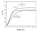
- FIG. 6 is a table showing the Rtp of coated paper with different mass ratios of CNTs and inorganic fillers. Further, FIG. 6 shows the thickness of the coating layer, the surface resistivity of the coating layer, and the thermal conductivity of the dry film. 7-10 are graphs showing Rtp of coated paper versus frequency.
- the Rtp shown in FIG. 6 is obtained by reading the values at 6 GHz and 15 GHz from the graphs shown in FIGS. 7-10.
- the thermal conductivity as shown in FIG. 6, all the samples were greater than 1.10, indicating high thermal conductivity.
- the dry film using graphite had a higher thermal conductivity than the dry film using carbon black.
- Graphite was found to be an inorganic filler more suitable than carbon black for achieving both electromagnetic noise suppression performance and thermal conductivity.
- the coated paper using "SB720" as the inorganic filler had a higher Rtp than the coated paper using "Asahi Thermal”.
- the iodine adsorption amount of "SB720” is 138 mg/g, and the iodine adsorption amount of "Asahi Thermal” is 27 mg/g.
- the DBP absorption of "SB720” is 59 ml/100 g, and the DBP absorption of "Asahi Thermal" is 28 ml/100 g. Therefore, it was found that carbon black with a large iodine adsorption amount and DBP absorption amount tends to have a large Rtp.
- Kaolin Kaolin, light calcium carbonate (hereinafter also referred to as “light calcium”), and heavy calcium carbonate (hereinafter also referred to as “heavy calcium”) were used as inorganic fillers.
- As kaolin "Hydrogloss 90" manufactured by Imerys Minerals Japan Co., Ltd. was used.
- As light calcium “Tamapearl TP121” manufactured by Okutama Industry Co., Ltd. was used.
- Heavy calcium “Softon 1500” manufactured by Bihoku Funka Kogyo Co., Ltd. was used.
- FIG. 11 is a table showing the Rtp of coated paper with different mass ratios of CNTs and inorganic fillers. Further, FIG. 11 shows the thickness of the coating layer, the surface resistivity of the coating layer, and the thermal conductivity of the dry film. 12-15 are graphs showing Rtp of coated paper versus frequency.
- the Rtp shown in FIG. 11 is obtained by reading the values at 6 GHz and 15 GHz from the graphs shown in FIGS. 12-15.
- the thermal conductivity as shown in FIG. 11, all the samples were greater than 1.10, indicating high thermal conductivity. It was found that by setting CNT:CMC in the range of 4:1 to 1:2, both electromagnetic noise suppression performance and thermal conductivity can be enhanced, and cost reduction can be achieved.
- the Rtp of the coated paper using non-conductive inorganic pigments was almost the same as that of the coated paper using conductive carbon black and graphite. .
- the thermal conductivity the dry film using the inorganic pigment did not reach the dry film using the graphite, but it was comparable to the carbon black "SB720". This is because inorganic pigments have a smaller thermal diffusivity than carbon black, but inorganic pigments have a higher density and specific heat than carbon black.
- the coated papers using kaolin tended to have a higher Rtp than the coated papers using light and heavy calcium. It was found that kaolin is an inorganic filler that is more suitable for achieving both electromagnetic noise suppression performance and thermal conductivity than light and heavy calcium. Kaolin has a higher aspect ratio than light cal and heavy cal and tends to be smooth. Therefore, kaolin has a high surface resistivity and a large Rtp.
- the present invention is not limited to the above-described embodiments, and various modifications are possible.
- the present invention includes configurations that are substantially the same as the configurations described in the embodiments. "Substantially the same configuration” means, for example, a configuration having the same function, method, and result, or a configuration having the same purpose and effect.
- the present invention includes configurations in which non-essential portions of the configurations described in the embodiments are replaced.
- the present invention includes a configuration that achieves the same effects as the configuration described in the embodiment or a configuration that can achieve the same object.
- the present invention includes configurations obtained by adding known techniques to the configurations described in the embodiments.
Landscapes
- Chemical & Material Sciences (AREA)
- Health & Medical Sciences (AREA)
- Chemical Kinetics & Catalysis (AREA)
- Medicinal Chemistry (AREA)
- Polymers & Plastics (AREA)
- Organic Chemistry (AREA)
- Engineering & Computer Science (AREA)
- Manufacturing & Machinery (AREA)
- Materials Engineering (AREA)
- Physics & Mathematics (AREA)
- Microelectronics & Electronic Packaging (AREA)
- Electromagnetism (AREA)
- Nanotechnology (AREA)
- Textile Engineering (AREA)
- Thermal Sciences (AREA)
- Dispersion Chemistry (AREA)
- Shielding Devices Or Components To Electric Or Magnetic Fields (AREA)
- Laminated Bodies (AREA)
Priority Applications (7)
| Application Number | Priority Date | Filing Date | Title |
|---|---|---|---|
| EP21931617.1A EP4311386A4 (en) | 2021-03-19 | 2021-03-19 | ELECTROMAGNETIC WAVE NOISE SUPPRESSION FILM AND MANUFACTURING METHOD THEREFOR |
| CN202180095930.8A CN117121648A (zh) | 2021-03-19 | 2021-03-19 | 电磁波噪声抑制片及其制造方法 |
| PCT/JP2021/011477 WO2022195871A1 (ja) | 2021-03-19 | 2021-03-19 | 電磁波ノイズ抑制シートおよびその製造方法 |
| KR1020237033733A KR102888073B1 (ko) | 2021-03-19 | 2021-03-19 | 전자파 노이즈 억제 시트 및 그 제조방법 |
| US18/275,376 US12446201B2 (en) | 2021-03-19 | 2021-03-19 | Electromagnetic wave noise suppression sheet and method for manufacturing the same |
| JP2023506686A JP7743497B2 (ja) | 2021-03-19 | 2021-03-19 | 電磁波ノイズ抑制シートおよびその製造方法 |
| TW110111766A TWI806029B (zh) | 2021-03-19 | 2021-03-31 | 電磁雜訊抑制用薄片及其製造方法 |
Applications Claiming Priority (1)
| Application Number | Priority Date | Filing Date | Title |
|---|---|---|---|
| PCT/JP2021/011477 WO2022195871A1 (ja) | 2021-03-19 | 2021-03-19 | 電磁波ノイズ抑制シートおよびその製造方法 |
Publications (1)
| Publication Number | Publication Date |
|---|---|
| WO2022195871A1 true WO2022195871A1 (ja) | 2022-09-22 |
Family
ID=83322109
Family Applications (1)
| Application Number | Title | Priority Date | Filing Date |
|---|---|---|---|
| PCT/JP2021/011477 Ceased WO2022195871A1 (ja) | 2021-03-19 | 2021-03-19 | 電磁波ノイズ抑制シートおよびその製造方法 |
Country Status (7)
| Country | Link |
|---|---|
| US (1) | US12446201B2 (https=) |
| EP (1) | EP4311386A4 (https=) |
| JP (1) | JP7743497B2 (https=) |
| KR (1) | KR102888073B1 (https=) |
| CN (1) | CN117121648A (https=) |
| TW (1) | TWI806029B (https=) |
| WO (1) | WO2022195871A1 (https=) |
Citations (3)
| Publication number | Priority date | Publication date | Assignee | Title |
|---|---|---|---|---|
| JP2013082610A (ja) * | 2011-09-29 | 2013-05-09 | Kj Specialty Paper Co Ltd | カーボンナノチューブ水分散液及びそれを用いて得られる複合シート |
| JP2013199419A (ja) * | 2012-02-23 | 2013-10-03 | Toray Ind Inc | カーボンナノチューブ分散液 |
| WO2016136428A1 (ja) * | 2015-02-25 | 2016-09-01 | 東レ株式会社 | カーボンナノチューブ分散液および導電性フィルムの製造方法 |
Family Cites Families (38)
| Publication number | Priority date | Publication date | Assignee | Title |
|---|---|---|---|---|
| US6493507B2 (en) * | 1997-01-30 | 2002-12-10 | Ival O. Salyer | Water heating unit with integral thermal energy storage |
| ATE502030T1 (de) * | 2000-11-20 | 2011-04-15 | Takeda Pharmaceutical | Imidazolderivate, verfahren zu deren herstellung und deren verwendung |
| JP2006114877A (ja) * | 2004-09-15 | 2006-04-27 | Suzuki Sogyo Co Ltd | 電磁波吸収シート、電磁波吸収シート積層体及びそれらを用いた電磁波吸収性ハウジング |
| JP4528324B2 (ja) | 2007-01-11 | 2010-08-18 | 本田技研工業株式会社 | 熱輸送流体およびその製造方法 |
| JP5000321B2 (ja) * | 2007-02-05 | 2012-08-15 | 日東電工株式会社 | 粘着剤層の製造方法 |
| CN101952906B (zh) | 2008-03-25 | 2012-12-19 | 东丽株式会社 | 导电性复合体及其制造方法 |
| CN101353547B (zh) * | 2008-07-08 | 2012-06-13 | 东莞市艾斯迪新材料有限公司 | 一种高弹水性导电纳米涂料 |
| KR100874690B1 (ko) * | 2008-09-19 | 2008-12-18 | 두성산업 주식회사 | 전자파 차폐 및 흡수 특성과 방열 특성이 향상된 롤 타입의복합 시트 및 그 제조 방법 |
| EP2404873A4 (en) | 2009-03-04 | 2016-04-06 | Toray Industries | COMPOSITION WITH CARBON NANOTONES, CATALYST FOR THE PRODUCTION OF CARBON CANNULARS AND AQUEOUS DISPERSION OF CARBON NANOTONES |
| US9613758B2 (en) | 2009-12-22 | 2017-04-04 | Pasi Moilanen | Fabrication and application of polymer-graphitic material nanocomposites and hybride materials |
| JP5413215B2 (ja) * | 2010-01-25 | 2014-02-12 | 三菱エンジニアリングプラスチックス株式会社 | 電磁波抑制用樹脂組成物及び成形品 |
| TWI515165B (zh) | 2010-10-29 | 2016-01-01 | 東麗股份有限公司 | 碳奈米管集合體分散液之製造方法 |
| JP5571014B2 (ja) * | 2011-02-21 | 2014-08-13 | Kj特殊紙株式会社 | 電磁波抑制シート |
| JP2012174833A (ja) | 2011-02-21 | 2012-09-10 | Kj Specialty Paper Co Ltd | 電磁波吸収シート |
| CN103842456A (zh) * | 2011-09-30 | 2014-06-04 | 3M创新有限公司 | 适形涂层和组合物 |
| JP5807112B2 (ja) * | 2012-03-29 | 2015-11-10 | 住友理工株式会社 | 導電膜 |
| WO2014071502A1 (en) * | 2012-11-09 | 2014-05-15 | Yonghao Ni | Anti-static articles and materials |
| JP2014133842A (ja) * | 2013-01-11 | 2014-07-24 | Yazaki Corp | 導電性樹脂組成物 |
| WO2015064708A1 (ja) | 2013-11-01 | 2015-05-07 | 公立大学法人大阪府立大学 | 導電性シート、その製造方法、カーボン複合ペースト、カーボン複合フィラー、導電性樹脂材料、および導電性ゴム材料 |
| RU2572840C2 (ru) | 2014-05-22 | 2016-01-20 | Мсд Текнолоджис Частная Компания С Ограниченной Ответственностью | Металлическая фольга с проводящим слоем и способ ее изготовления |
| KR102305509B1 (ko) * | 2014-07-22 | 2021-09-28 | 씨-나노 테크놀로지 리미티드 | 배터리용 전극 조성물 |
| JP2016134269A (ja) * | 2015-01-19 | 2016-07-25 | トヨタ自動車株式会社 | 電極の製造方法 |
| JP2016168810A (ja) * | 2015-03-16 | 2016-09-23 | 東レ株式会社 | 導電積層体 |
| JP6454445B2 (ja) | 2016-11-04 | 2019-01-16 | マクセルホールディングス株式会社 | 電磁波吸収シート |
| CN106684319A (zh) * | 2016-12-23 | 2017-05-17 | 国联汽车动力电池研究院有限责任公司 | 一种类单面极片、含有其的轻量化电芯及制备方法 |
| JPWO2018180350A1 (ja) | 2017-03-31 | 2020-02-06 | 日本ゼオン株式会社 | 繊維状炭素ナノ構造体分散液の製造方法および繊維状炭素ナノ構造体分散液 |
| CN108034345B (zh) | 2017-12-16 | 2020-11-20 | 国网辽宁省电力有限公司电力科学研究院 | 一种高效吸收工频电磁场的涂料 |
| CN108084823B (zh) * | 2017-12-18 | 2019-05-17 | 中南大学 | 一种电热涂料及其制备方法和应用 |
| JP7081294B2 (ja) | 2018-05-11 | 2022-06-07 | トヨタ自動車株式会社 | 電子ユニット |
| JP7402603B2 (ja) | 2018-07-13 | 2023-12-21 | 株式会社ミルボン | 前処理剤、及び酸化染毛方法又は脱色方法 |
| JP6585250B1 (ja) | 2018-08-22 | 2019-10-02 | 株式会社 美粒 | 乳化分散液 |
| WO2020194380A1 (ja) * | 2019-03-22 | 2020-10-01 | 北越コーポレーション株式会社 | ナノカーボン分散液及びその製造方法並びにナノカーボン分散剤 |
| CN110591579B (zh) | 2019-08-13 | 2021-08-31 | 深圳烯湾科技有限公司 | 电磁屏蔽散热膜及其制备方法和应用 |
| JP7277338B2 (ja) * | 2019-10-31 | 2023-05-18 | 北越コーポレーション株式会社 | 電磁波シールドシートの製造方法、および電磁波シールドシート |
| JP7470939B2 (ja) | 2020-01-28 | 2024-04-19 | 日本ゼオン株式会社 | 電磁波遮蔽シート |
| KR20220131972A (ko) * | 2020-04-01 | 2022-09-29 | 호쿠에츠 코포레이션 가부시키가이샤 | 전자파 차폐시트 제조방법 및 전자파 차폐시트 |
| CN111763459A (zh) | 2020-06-23 | 2020-10-13 | 杭州立兴新材料科技有限公司 | 一种复合改性电磁屏蔽水性涂料及其制造方法 |
| CN112105248B (zh) | 2020-08-07 | 2021-06-15 | 中国科学院山西煤炭化学研究所 | 一种电磁屏蔽膜及其制备方法 |
-
2021
- 2021-03-19 KR KR1020237033733A patent/KR102888073B1/ko active Active
- 2021-03-19 JP JP2023506686A patent/JP7743497B2/ja active Active
- 2021-03-19 EP EP21931617.1A patent/EP4311386A4/en active Pending
- 2021-03-19 WO PCT/JP2021/011477 patent/WO2022195871A1/ja not_active Ceased
- 2021-03-19 US US18/275,376 patent/US12446201B2/en active Active
- 2021-03-19 CN CN202180095930.8A patent/CN117121648A/zh active Pending
- 2021-03-31 TW TW110111766A patent/TWI806029B/zh active
Patent Citations (3)
| Publication number | Priority date | Publication date | Assignee | Title |
|---|---|---|---|---|
| JP2013082610A (ja) * | 2011-09-29 | 2013-05-09 | Kj Specialty Paper Co Ltd | カーボンナノチューブ水分散液及びそれを用いて得られる複合シート |
| JP2013199419A (ja) * | 2012-02-23 | 2013-10-03 | Toray Ind Inc | カーボンナノチューブ分散液 |
| WO2016136428A1 (ja) * | 2015-02-25 | 2016-09-01 | 東レ株式会社 | カーボンナノチューブ分散液および導電性フィルムの製造方法 |
Non-Patent Citations (1)
| Title |
|---|
| See also references of EP4311386A4 * |
Also Published As
| Publication number | Publication date |
|---|---|
| CN117121648A (zh) | 2023-11-24 |
| TW202239311A (zh) | 2022-10-01 |
| US20240107733A1 (en) | 2024-03-28 |
| KR102888073B1 (ko) | 2025-11-19 |
| TWI806029B (zh) | 2023-06-21 |
| EP4311386A4 (en) | 2025-01-01 |
| EP4311386A1 (en) | 2024-01-24 |
| KR20230154060A (ko) | 2023-11-07 |
| JP7743497B2 (ja) | 2025-09-24 |
| JPWO2022195871A1 (https=) | 2022-09-22 |
| US12446201B2 (en) | 2025-10-14 |
Similar Documents
| Publication | Publication Date | Title |
|---|---|---|
| JP6313755B2 (ja) | 紙製バリア包装材料 | |
| CN115516168B (zh) | 适合于金属化的涂覆的纸基材 | |
| CN101827975A (zh) | 薄片状物及其制造方法 | |
| JP7177912B2 (ja) | ナノカーボン分散液の製造方法、ナノカーボン分散剤及び電磁波遮蔽材 | |
| JP7540067B2 (ja) | 電磁波シールドシートの製造方法、および電磁波シールドシート | |
| US12428544B2 (en) | Electromagnetic wave shield sheet manufacturing method and electromagnetic wave shield sheet | |
| CA3179407A1 (en) | Process for production of nano-coated substrate | |
| JP7277338B2 (ja) | 電磁波シールドシートの製造方法、および電磁波シールドシート | |
| JP7265028B2 (ja) | カーボンナノチューブ水分散液の製造方法 | |
| JP2024022443A (ja) | カーボンナノチューブ水分散液および電磁波ノイズ抑制シート | |
| JP7743497B2 (ja) | 電磁波ノイズ抑制シートおよびその製造方法 | |
| JP7789752B2 (ja) | 電磁波ノイズ抑制シートの製造方法 | |
| JP7714851B2 (ja) | 電磁波吸収体およびその製造方法 | |
| JP7669117B2 (ja) | 電磁波シールドシートの製造方法、および電磁波シールドシート | |
| JP2026049310A (ja) | 電磁波吸収体 |
Legal Events
| Date | Code | Title | Description |
|---|---|---|---|
| 121 | Ep: the epo has been informed by wipo that ep was designated in this application |
Ref document number: 21931617 Country of ref document: EP Kind code of ref document: A1 |
|
| ENP | Entry into the national phase |
Ref document number: 2023506686 Country of ref document: JP Kind code of ref document: A |
|
| WWE | Wipo information: entry into national phase |
Ref document number: 18275376 Country of ref document: US |
|
| ENP | Entry into the national phase |
Ref document number: 20237033733 Country of ref document: KR Kind code of ref document: A |
|
| WWE | Wipo information: entry into national phase |
Ref document number: 1020237033733 Country of ref document: KR |
|
| WWE | Wipo information: entry into national phase |
Ref document number: 2021931617 Country of ref document: EP |
|
| NENP | Non-entry into the national phase |
Ref country code: DE |
|
| ENP | Entry into the national phase |
Ref document number: 2021931617 Country of ref document: EP Effective date: 20231019 |
|
| WWG | Wipo information: grant in national office |
Ref document number: 18275376 Country of ref document: US |