WO2022185152A1 - 二次電池の充電方法 - Google Patents
二次電池の充電方法 Download PDFInfo
- Publication number
- WO2022185152A1 WO2022185152A1 PCT/IB2022/051616 IB2022051616W WO2022185152A1 WO 2022185152 A1 WO2022185152 A1 WO 2022185152A1 IB 2022051616 W IB2022051616 W IB 2022051616W WO 2022185152 A1 WO2022185152 A1 WO 2022185152A1
- Authority
- WO
- WIPO (PCT)
- Prior art keywords
- secondary battery
- charging
- voltage
- positive electrode
- time
- Prior art date
- Legal status (The legal status is an assumption and is not a legal conclusion. Google has not performed a legal analysis and makes no representation as to the accuracy of the status listed.)
- Ceased
Links
Images




























































Classifications
-
- H—ELECTRICITY
- H02—GENERATION; CONVERSION OR DISTRIBUTION OF ELECTRIC POWER
- H02J—ELECTRIC POWER NETWORKS; CIRCUIT ARRANGEMENTS OR SYSTEMS FOR SUPPLYING OR DISTRIBUTING ELECTRIC POWER; SYSTEMS FOR STORING ELECTRIC ENERGY
- H02J7/00—Circuit arrangements for charging or discharging batteries or for supplying loads from batteries
- H02J7/02—Circuit arrangements for charging or discharging batteries or for supplying loads from batteries for charging batteries from AC mains by converters
- H02J7/04—Regulation of charging current or voltage
-
- H—ELECTRICITY
- H01—ELECTRIC ELEMENTS
- H01M—PROCESSES OR MEANS, e.g. BATTERIES, FOR THE DIRECT CONVERSION OF CHEMICAL ENERGY INTO ELECTRICAL ENERGY
- H01M10/00—Secondary cells; Manufacture thereof
- H01M10/42—Methods or arrangements for servicing or maintenance of secondary cells or secondary half-cells
- H01M10/44—Methods for charging or discharging
-
- C—CHEMISTRY; METALLURGY
- C01—INORGANIC CHEMISTRY
- C01G—COMPOUNDS CONTAINING METALS NOT COVERED BY SUBCLASSES C01D OR C01F
- C01G51/00—Compounds of cobalt
-
- C—CHEMISTRY; METALLURGY
- C01—INORGANIC CHEMISTRY
- C01G—COMPOUNDS CONTAINING METALS NOT COVERED BY SUBCLASSES C01D OR C01F
- C01G51/00—Compounds of cobalt
- C01G51/40—Complex oxides containing cobalt and at least one other metal element
- C01G51/42—Complex oxides containing cobalt and at least one other metal element containing alkali metals, e.g. LiCoO2
-
- H—ELECTRICITY
- H01—ELECTRIC ELEMENTS
- H01M—PROCESSES OR MEANS, e.g. BATTERIES, FOR THE DIRECT CONVERSION OF CHEMICAL ENERGY INTO ELECTRICAL ENERGY
- H01M10/00—Secondary cells; Manufacture thereof
- H01M10/05—Accumulators with non-aqueous electrolyte
- H01M10/052—Li-accumulators
- H01M10/0525—Rocking-chair batteries, i.e. batteries with lithium insertion or intercalation in both electrodes; Lithium-ion batteries
-
- H—ELECTRICITY
- H01—ELECTRIC ELEMENTS
- H01M—PROCESSES OR MEANS, e.g. BATTERIES, FOR THE DIRECT CONVERSION OF CHEMICAL ENERGY INTO ELECTRICAL ENERGY
- H01M10/00—Secondary cells; Manufacture thereof
- H01M10/42—Methods or arrangements for servicing or maintenance of secondary cells or secondary half-cells
- H01M10/44—Methods for charging or discharging
- H01M10/443—Methods for charging or discharging in response to temperature
-
- H—ELECTRICITY
- H01—ELECTRIC ELEMENTS
- H01M—PROCESSES OR MEANS, e.g. BATTERIES, FOR THE DIRECT CONVERSION OF CHEMICAL ENERGY INTO ELECTRICAL ENERGY
- H01M10/00—Secondary cells; Manufacture thereof
- H01M10/42—Methods or arrangements for servicing or maintenance of secondary cells or secondary half-cells
- H01M10/48—Accumulators combined with arrangements for measuring, testing or indicating the condition of cells, e.g. the level or density of the electrolyte
-
- H—ELECTRICITY
- H01—ELECTRIC ELEMENTS
- H01M—PROCESSES OR MEANS, e.g. BATTERIES, FOR THE DIRECT CONVERSION OF CHEMICAL ENERGY INTO ELECTRICAL ENERGY
- H01M4/00—Electrodes
- H01M4/02—Electrodes composed of, or comprising, active material
- H01M4/36—Selection of substances as active materials, active masses, active liquids
- H01M4/48—Selection of substances as active materials, active masses, active liquids of inorganic oxides or hydroxides
- H01M4/52—Selection of substances as active materials, active masses, active liquids of inorganic oxides or hydroxides of nickel, cobalt or iron
- H01M4/525—Selection of substances as active materials, active masses, active liquids of inorganic oxides or hydroxides of nickel, cobalt or iron of mixed oxides or hydroxides containing iron, cobalt or nickel for inserting or intercalating light metals, e.g. LiNiO2, LiCoO2 or LiCoOxFy
-
- H—ELECTRICITY
- H02—GENERATION; CONVERSION OR DISTRIBUTION OF ELECTRIC POWER
- H02J—ELECTRIC POWER NETWORKS; CIRCUIT ARRANGEMENTS OR SYSTEMS FOR SUPPLYING OR DISTRIBUTING ELECTRIC POWER; SYSTEMS FOR STORING ELECTRIC ENERGY
- H02J7/00—Circuit arrangements for charging or discharging batteries or for supplying loads from batteries
- H02J7/02—Circuit arrangements for charging or discharging batteries or for supplying loads from batteries for charging batteries from AC mains by converters
-
- H—ELECTRICITY
- H02—GENERATION; CONVERSION OR DISTRIBUTION OF ELECTRIC POWER
- H02J—ELECTRIC POWER NETWORKS; CIRCUIT ARRANGEMENTS OR SYSTEMS FOR SUPPLYING OR DISTRIBUTING ELECTRIC POWER; SYSTEMS FOR STORING ELECTRIC ENERGY
- H02J7/00—Circuit arrangements for charging or discharging batteries or for supplying loads from batteries
- H02J7/02—Circuit arrangements for charging or discharging batteries or for supplying loads from batteries for charging batteries from AC mains by converters
- H02J7/04—Regulation of charging current or voltage
- H02J7/06—Regulation of charging current or voltage using discharge tubes or semiconductor devices
-
- H—ELECTRICITY
- H02—GENERATION; CONVERSION OR DISTRIBUTION OF ELECTRIC POWER
- H02J—ELECTRIC POWER NETWORKS; CIRCUIT ARRANGEMENTS OR SYSTEMS FOR SUPPLYING OR DISTRIBUTING ELECTRIC POWER; SYSTEMS FOR STORING ELECTRIC ENERGY
- H02J7/00—Circuit arrangements for charging or discharging batteries or for supplying loads from batteries
- H02J7/80—Circuit arrangements for charging or discharging batteries or for supplying loads from batteries including monitoring or indicating arrangements
-
- H—ELECTRICITY
- H02—GENERATION; CONVERSION OR DISTRIBUTION OF ELECTRIC POWER
- H02J—ELECTRIC POWER NETWORKS; CIRCUIT ARRANGEMENTS OR SYSTEMS FOR SUPPLYING OR DISTRIBUTING ELECTRIC POWER; SYSTEMS FOR STORING ELECTRIC ENERGY
- H02J7/00—Circuit arrangements for charging or discharging batteries or for supplying loads from batteries
- H02J7/90—Regulation of charging or discharging current or voltage
- H02J7/96—Regulation of charging or discharging current or voltage in response to battery voltage
- H02J7/963—Regulation of charging or discharging current or voltage in response to battery voltage in response to battery voltage gradient
-
- H—ELECTRICITY
- H01—ELECTRIC ELEMENTS
- H01M—PROCESSES OR MEANS, e.g. BATTERIES, FOR THE DIRECT CONVERSION OF CHEMICAL ENERGY INTO ELECTRICAL ENERGY
- H01M4/00—Electrodes
- H01M4/02—Electrodes composed of, or comprising, active material
- H01M2004/026—Electrodes composed of, or comprising, active material characterised by the polarity
- H01M2004/028—Positive electrodes
-
- H—ELECTRICITY
- H01—ELECTRIC ELEMENTS
- H01M—PROCESSES OR MEANS, e.g. BATTERIES, FOR THE DIRECT CONVERSION OF CHEMICAL ENERGY INTO ELECTRICAL ENERGY
- H01M10/00—Secondary cells; Manufacture thereof
- H01M10/42—Methods or arrangements for servicing or maintenance of secondary cells or secondary half-cells
- H01M10/425—Structural combination with electronic components, e.g. electronic circuits integrated to the outside of the casing
- H01M2010/4271—Battery management systems including electronic circuits, e.g. control of current or voltage to keep battery in healthy state, cell balancing
-
- H—ELECTRICITY
- H02—GENERATION; CONVERSION OR DISTRIBUTION OF ELECTRIC POWER
- H02J—ELECTRIC POWER NETWORKS; CIRCUIT ARRANGEMENTS OR SYSTEMS FOR SUPPLYING OR DISTRIBUTING ELECTRIC POWER; SYSTEMS FOR STORING ELECTRIC ENERGY
- H02J7/00—Circuit arrangements for charging or discharging batteries or for supplying loads from batteries
- H02J7/90—Regulation of charging or discharging current or voltage
- H02J7/96—Regulation of charging or discharging current or voltage in response to battery voltage
-
- Y—GENERAL TAGGING OF NEW TECHNOLOGICAL DEVELOPMENTS; GENERAL TAGGING OF CROSS-SECTIONAL TECHNOLOGIES SPANNING OVER SEVERAL SECTIONS OF THE IPC; TECHNICAL SUBJECTS COVERED BY FORMER USPC CROSS-REFERENCE ART COLLECTIONS [XRACs] AND DIGESTS
- Y02—TECHNOLOGIES OR APPLICATIONS FOR MITIGATION OR ADAPTATION AGAINST CLIMATE CHANGE
- Y02E—REDUCTION OF GREENHOUSE GAS [GHG] EMISSIONS, RELATED TO ENERGY GENERATION, TRANSMISSION OR DISTRIBUTION
- Y02E60/00—Enabling technologies; Technologies with a potential or indirect contribution to GHG emissions mitigation
- Y02E60/10—Energy storage using batteries
Definitions
- One aspect of the present invention relates to a power storage system, a method of operating the power storage system, a secondary battery, and a method of operating the secondary battery.
- One embodiment of the present invention also relates to a method for charging a secondary battery.
- Another embodiment of the present invention relates to a semiconductor device and an operation method of the semiconductor device.
- Another aspect of the present invention relates to a battery control circuit, a battery protection circuit, a power storage device, an electric device, and an operation method thereof.
- one aspect of the present invention is not limited to the above technical field.
- the technical field of the invention disclosed in this specification and the like relates to products and methods.
- one aspect of the invention relates to a process, machine, manufacture, or composition of matter. Therefore, technical fields of one embodiment of the present invention disclosed in this specification more specifically include display devices, light-emitting devices, power storage devices, imaging devices, storage devices, driving methods thereof, and manufacturing methods thereof; can be mentioned as an example.
- Power storage devices also called batteries or secondary batteries
- batteries are used in a wide range of fields, from small electronic devices to automobiles.
- applications using multi-cell configuration battery stacks in which a plurality of battery cells are connected in series are increasing.
- the power storage device is equipped with a circuit for detecting abnormalities during charging and discharging, such as overdischarge, overcharge, overcurrent, or short circuit.
- a circuit for detecting abnormalities during charging and discharging such as overdischarge, overcharge, overcurrent, or short circuit.
- data such as voltage and current are acquired, and based on the data, control such as suspension of charging and discharging or cell balancing is performed. Thereby, protection and control of the battery can be performed.
- Patent Document 1 discloses a protection IC that functions as a battery protection circuit. Specifically, in Patent Document 1, a protection IC that provides a plurality of comparators inside and compares a reference voltage with the voltage of a terminal connected to a battery to detect an abnormality during charging and discharging. is disclosed.
- Patent Document 2 also discloses a battery state detection device that detects a micro short circuit in a secondary battery and a battery pack containing the same.
- Patent Document 3 discloses a protective semiconductor device that protects an assembled battery in which secondary battery cells are connected in series.
- Another object of one embodiment of the present invention is to provide a highly reliable positive electrode active material. Another object of one embodiment of the present invention is to provide an excellent power storage system by applying the positive electrode active material of one embodiment of the present invention to the power storage system of one embodiment of the present invention. Another object of one embodiment of the present invention is to estimate the state of a secondary battery. Another object of one embodiment of the present invention is to estimate the charging depth of a secondary battery. Another object of one embodiment of the present invention is to estimate the fully chargeable capacity of a secondary battery and estimate the deterioration state of the secondary battery. Another object of one embodiment of the present invention is to estimate the dischargeable capacity of a secondary battery.
- an object of one embodiment of the present invention is to provide a novel charger, charging control circuit, battery control circuit, battery protection circuit, power storage device, semiconductor device, vehicle, electronic device, or the like.
- Another object of one embodiment of the present invention is to provide a charger, a charging control circuit, a battery control circuit, a battery protection circuit, a power storage device, a semiconductor device, a vehicle, an electronic device, or the like with low power consumption.
- Another object of one embodiment of the present invention is to provide a highly integrated charger, charging control circuit, battery control circuit, battery protection circuit, power storage device, semiconductor device, vehicle, electronic device, or the like. .
- the problem of one embodiment of the present invention is not limited to the problems listed above.
- the issues listed above do not preclude the existence of other issues.
- Still other issues are issues not mentioned in this section, which will be described in the following description. Problems not mentioned in this section can be derived from the descriptions in the specification, drawings, or the like by those skilled in the art, and can be appropriately extracted from these descriptions.
- One aspect of the present invention is to solve at least one of the problems listed above and/or other problems.
- the charger of one embodiment of the present invention can be particularly preferably used in combination with a secondary battery using the positive electrode active material of one embodiment of the present invention.
- the charger of one embodiment of the present invention measures the charging voltage and charging current of the secondary battery, and analyzes the measured charging voltage and charging current. It has the function of detecting changes in the crystal structure of substances.
- the charging capacity can be increased by maximizing the charging voltage in repeated charging and discharging.
- the change in the crystal structure of the positive electrode active material is approximately reversible even at a high charging voltage.
- the change in the crystal structure of the positive electrode active material is substantially reversible, the collapse of the crystal structure of the positive electrode active material during charging is suppressed, and the high capacity and long life are achieved. This is a charging method for the next battery.
- the charger of one embodiment of the present invention has a high charging voltage and a crystalline It has a function of detecting a change in the crystal structure of the positive electrode active material and controlling charging within a range in which the structural change is approximately reversible.
- the positive electrode active material of one embodiment of the present invention changes from an O3-type crystal structure to an O3′-type crystal structure, which will be described later. Moreover, this crystal structure change occurs in a state where the secondary battery is deeply charged.
- a charger of one embodiment of the present invention has a function of detecting a change from an O3-type crystal structure to an O3′-type crystal structure and controlling charging.
- One aspect of the present invention is a secondary battery charging method using a charger having a function of controlling the start and stop of charging of the secondary battery and a function of controlling the charging current of the secondary battery,
- the secondary battery has a positive electrode, the positive electrode has positive electrode active material particles, and the positive electrode active material particles are lithium cobalt oxide to which magnesium is added.
- "determined by X-ray diffraction" may be expressed as "identified by X-ray diffraction”.
- the charging depth of lithium cobalt oxide is preferably 70% or more.
- one embodiment of the present invention is a secondary battery charging method using a charger including a control circuit and a voltage measurement circuit, wherein the control circuit controls start and stop of charging of the secondary battery. and a function of controlling the charging current of the secondary battery, and the control circuit has a function of calculating the time change of the voltage of the secondary battery and detecting the maximum time change of the voltage of the secondary battery.
- the voltage measurement circuit has a function of measuring the charging voltage of the secondary battery, the control circuit starts charging the secondary battery at time t3, and the voltage measurement circuit measures the voltage at time t
- the secondary battery voltage V(t) and the secondary battery voltage V(t ⁇ t1) at time (t ⁇ t1) obtained by subtracting time ⁇ t1 from time t are measured.
- the control circuit stops charging at time t4 after the lapse of a predetermined time from time tq, and charges the secondary battery at a constant current from time t3 to time t4.
- the voltage V(tq) is a charging method for a secondary battery of 4.25V or more.
- control circuit has an analog-digital conversion circuit
- analog-digital conversion circuit has a function of converting the measured charging voltage from an analog value to a digital value.
- the resolution is 12 bits or less.
- the secondary battery has a positive electrode, the positive electrode contains lithium and cobalt, and at time tq, the crystal structure determined by powder X-ray diffraction is a crystal structure represented by the space group R-3m is preferably
- the charger has a memory circuit, data corresponding to the environmental temperature is stored in the memory circuit, and the time tq is detected using the data.
- the charger may have a memory circuit, and the memory circuit may store data corresponding to the positive electrode active material of the secondary battery, and the time tq may be detected using the data. preferable.
- One aspect of the present invention is a secondary battery charging method using a charger having a control circuit, a voltage measurement circuit, and a current measurement circuit, wherein the control circuit starts and stops charging of the secondary battery. and a function of controlling the charging current of the secondary battery, and the control circuit has a function of calculating the voltage differential of the electric quantity of the secondary battery and detecting the maximum of the voltage differential of the electric quantity.
- the voltage measuring circuit has a function of measuring the charging voltage of the secondary battery; the current measuring circuit has a function of measuring the charging current of the secondary battery;
- the charging of the next battery is started, and the electric quantity Q(t) is calculated using the current I(t) at time t, the horizontal axis is the voltage V(t), and the vertical axis is the voltage differentiation of the electric quantity Q(t) Analyze the first curve [dQ (t) / dV (t)], detect the time tp at which the first curve has the first maximum, and stop charging at time t2 after a predetermined time has passed from time tp and the voltage V(tp) at time tp is 4.25 V or higher.
- charging is preferably performed with a constant current.
- the secondary battery has a positive electrode, the positive electrode contains lithium and cobalt, and the crystal structure determined when the positive electrode is analyzed by powder X-ray diffraction at time tp is the space group R It is preferably a crystal structure represented by -3m.
- the positive electrode preferably contains lithium cobaltate, and the crystal structure of lithium cobaltate determined by powder X-ray diffraction at time tp is preferably represented by the space group R-3m.
- the charger have a memory circuit, store data corresponding to the environmental temperature in the memory circuit, and detect the time tp using the data.
- the charger has a memory circuit, the memory circuit stores data corresponding to the positive electrode active material of the secondary battery, and the time tp is detected using the data. is preferred.
- One aspect of the present invention is a secondary battery charging method using a charger having a control circuit, a voltage measurement circuit, and a current measurement circuit, wherein the control circuit starts and stops charging of the secondary battery. and a function of controlling the charging current of the secondary battery, and the control circuit has a function of calculating the time change of the voltage of the secondary battery and a function of detecting the maximum time change of the voltage and, the voltage measurement circuit has a function of measuring the charging voltage of the secondary battery, the current measurement circuit has a function of measuring the charging current of the secondary battery, and the control circuit has a function of measuring the charging current of the secondary battery at time t3 , the voltage measurement circuit measures the voltage V(t) of the secondary battery at time t and the voltage V of the secondary battery at time (t ⁇ t1) obtained by subtracting time ⁇ t1 from time t.
- the control circuit measures a second By analyzing the curves, the control circuit detects time tq at which the second curve has a first minimum, and the control circuit stops charging at time t4, a predetermined time after time tq, and the secondary In this charging method, the battery is charged at a constant current, and the voltage V(tq) of the secondary battery at time tq is 4.25 V or higher.
- the secondary battery has a positive electrode, the positive electrode contains lithium and cobalt, and the crystal structure determined when the positive electrode is analyzed by powder X-ray diffraction at time t3 is the space group R- A crystal structure represented by 3m is preferred.
- the positive electrode at time tq, the positive electrode preferably contains lithium cobaltate, and the crystal structure of lithium cobaltate determined by powder X-ray diffraction is preferably represented by the space group R-3m.
- the charger has a memory circuit, data corresponding to the environmental temperature is stored in the memory circuit, and the time tq is detected using the data.
- the charger may have a memory circuit, and the memory circuit may store data corresponding to the positive electrode active material of the secondary battery, and the time tq may be detected using the data. preferable.
- the positive electrode preferably contains lithium cobaltate.
- the positive electrode preferably has a metal oxide represented by LiMO 2 (M is a metal), and the metal M is preferably two or more metals including cobalt.
- One aspect of the present invention is a secondary battery charging method using a charger having a control circuit and a voltage measurement circuit, wherein the control circuit has a function of controlling start and stop of charging of the secondary battery. , a function of controlling the charging current of the secondary battery, the control circuit having a function of calculating the time change of the voltage of the secondary battery, and a function of detecting the maximum of the time change, and the voltage
- the measurement circuit has a function of measuring the charging voltage of the secondary battery.
- the control circuit starts constant current charging of the secondary battery, and the voltage measurement circuit measures the voltage V of the secondary battery.
- the control circuit compares the voltage V with a predetermined voltage V1, and proceeds to the fourth step if the voltage V is greater than or equal to the voltage V1, and proceeds to the fourth step if the voltage V is less than V1.
- the third step the control circuit accumulates paired data of dt/dV and time t, [dt/dV]mean, which is the moving average of dt/dV, and the accumulated dt a fourth step of calculating [dt/dV]max, which is the maximum value of /dV; , and if [dt/dV]mean is less than [dt/dV]max multiplied by constant Rt, go to a sixth step, where [dt/dV]mean is [dt/dV] a fifth step where the control circuit stops constant current charging of the secondary battery, wherein the control circuit stops constant current charging of the secondary battery. It is a battery charging method.
- the voltage V1 is 4.25 V or more and the constant Rt is 0.6 or more and 0.9 or less.
- a power storage system with high energy density can be provided.
- a highly safe power storage system can be provided.
- a secondary battery with high energy density can be provided.
- a highly safe secondary battery can be provided.
- a novel charging method for a secondary battery can be provided.
- a power storage system using a highly reliable positive electrode active material can be provided.
- a highly reliable positive electrode active material can be provided.
- the positive electrode active material of one embodiment of the present invention can be applied to the power storage system of one embodiment of the present invention, so that an excellent power storage system can be provided.
- the state of a secondary battery can be estimated.
- the charging depth of a secondary battery can be estimated.
- the fully chargeable capacity of the secondary battery can be estimated, and the deterioration state of the secondary battery can be estimated.
- the dischargeable capacity of a secondary battery can be estimated.
- novel chargers, charging control circuits, battery control circuits, battery protection circuits, power storage devices, semiconductor devices, vehicles, electronic devices, and the like can be provided.
- a charger, a charging control circuit, a battery control circuit, a battery protection circuit, a power storage device, a semiconductor device, a vehicle, an electronic device, or the like with low power consumption can be provided.
- highly integrated chargers, charging control circuits, battery control circuits, battery protection circuits, power storage devices, semiconductor devices, vehicles, electronic devices, and the like can be provided.
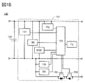
- FIG. 1A is a block diagram showing an example of a power storage system.
- FIG. 1B is a block diagram illustrating an example of a power storage system;
- FIG. 2A is a block diagram showing an example of a power storage system.
- FIG. 2B is a block diagram illustrating an example of a power storage system;
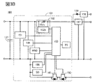
- FIG. 3A is a block diagram showing an example of a power storage system.
- FIG. 3B is a block diagram illustrating an example of a power storage system;
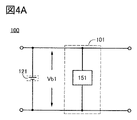
- FIG. 4A is a block diagram showing an example of a power storage system.
- FIG. 4B is a block diagram illustrating an example of a power storage system;
- FIG. 5 is a flow diagram illustrating a method of charging a secondary battery.
- FIG. 6 is a flowchart for explaining a method of charging a secondary battery.
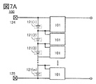
- FIG. 7A is a block diagram showing an example of a power storage system.
- FIG. 7B is a block diagram illustrating an example of a power storage system;
- FIG. 7C is a block diagram illustrating an example of a power storage system;
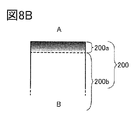
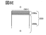
- 8A is a cross-sectional view of the positive electrode active material, and FIGS. 8B to 8E are part of the cross-sectional views of the positive electrode active material.
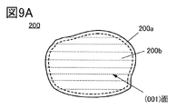
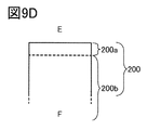
- 9A and 9B are cross-sectional views of the positive electrode active material, and FIGS. 9C and 9D are part of cross-sectional views of the positive electrode active material.
- FIG. 10 is a cross-sectional view of the positive electrode active material.
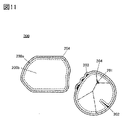
- FIG. 11 is a cross-sectional view of the positive electrode active material.
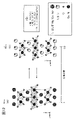
- FIG. 12 is a diagram for explaining the crystal structure of the positive electrode active material.
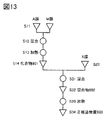
- FIG. 13 is a diagram illustrating an example of a method for producing a positive electrode active material.
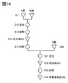
- FIG. 14 is a diagram illustrating an example of a method for producing a positive electrode active material.
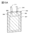
- 15A and 15B are diagrams showing an example of the appearance of a secondary battery.
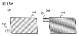
- 16A and 16B are diagrams illustrating a method for manufacturing a secondary battery.
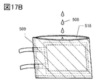
- 17A and 17B are diagrams illustrating a method for manufacturing a secondary battery.
- FIG. 18 is a cross-sectional view showing an example of a secondary battery.
- FIG. 19A is a diagram showing an example of a secondary battery.
- 19B and 19C are diagrams showing an example of a method for producing a laminate.
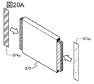
- 20A to 20C are diagrams illustrating an example of a method for manufacturing a secondary battery.
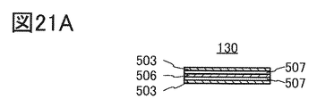
- 21A and 21B are cross-sectional views showing examples of laminates.
- FIG. 21C is a cross-sectional view showing an example of a secondary battery.
- 22A and 22B are diagrams showing an example of a secondary battery.
- FIG. 22C is a diagram showing the inside of the secondary battery.
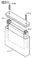
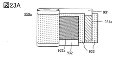
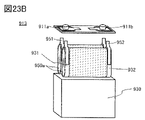
- 23A to 23C are diagrams showing an example of a secondary battery.
- FIG. 24 is a block diagram showing an example of a vehicle having a motor.
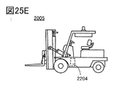
- 25A to 25E are diagrams showing an example of a transportation vehicle.
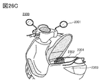
- FIG. 26A is a diagram showing an electric bicycle, FIG.
- FIG. 26B is a diagram showing a secondary battery of the electric bicycle, and FIG. 26C is a diagram explaining an electric motorcycle.
- 27A and 27B are diagrams illustrating an example of a power storage device.
- 28A to 28E are diagrams illustrating examples of electronic devices.
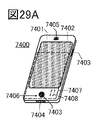
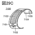
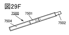
- 29A to 29F are diagrams illustrating examples of electronic devices.
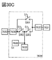
- 30A to 30C are diagrams illustrating an example of electronic equipment.
- FIG. 31 is a diagram illustrating an example of electronic equipment.
- 32A to 32C are diagrams illustrating examples of electronic devices.
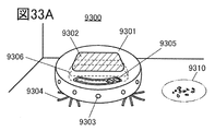
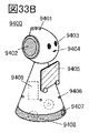
- 33A to 33D are diagrams showing examples of electronic devices.
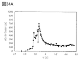
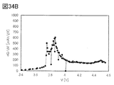
- Figures 34A and 34B are dQ/dV-V curves.
- Figures 35A and 35B are dQ/dV-V curves.
- FIG. 36A is the VC curve.
- FIG. 36A is the VC curve.
- FIG. 36B is the ⁇ Vt curve.
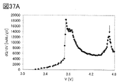
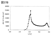
- Figures 37A and 37B are dQ/dV curves.
- FIG. 38A is a diagram showing the relationship between the number of charge/discharge cycles and discharge capacity.
- FIG. 38B is a diagram showing the relationship between the number of charge/discharge cycles and the discharge capacity retention rate.
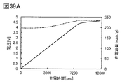
- 39A and 39B are diagrams showing the relationship between charging time and voltage and the relationship between charging time and charging capacity.
- FIG. 40A is a diagram showing the relationship between charging time and voltage, and the relationship between charging time and charging capacity.
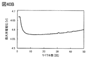
- FIG. 40B is a diagram showing the number of charge/discharge cycles and maximum charge voltage.
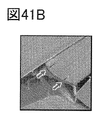
- Figures 41A and 41B show SEM images.
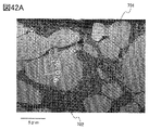
- Figures 42A and 42B show SEM images.
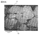
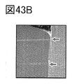
- Figures 43A and 43B show SEM images.
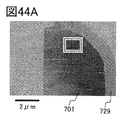
- FIG. 44A shows a transmission electron image.
- FIG. 44B shows a Z-contrast image.
- FIG. 44C shows a transmission electron image.
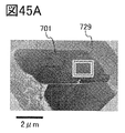
- FIG. 45A shows a transmission electron image.
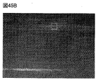
- FIG. 45B shows a Z-contrast image.
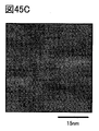
- FIG. 45C shows a transmission electron image.
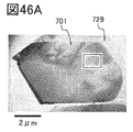
- FIG. 46A shows a transmission electron image.
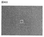
- FIG. 46B shows a Z-contrast image.
- FIG. 46C shows a transmission electron image.
- FIG. 47A shows a transmission electron image.
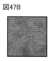
- FIG. 47B shows a Z-contrast image.
- FIG. 47C shows a transmission electron image.
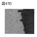
- Figures 47D to 47F show EDX surface analysis results.
- FIG. 48A shows a transmission electron image.
- FIG. 48B shows a Z-contrast image.
- FIG. 48A shows a transmission electron image.
- FIG. 48B shows a Z-contrast image.
- FIG. 48A shows a transmission electron image.
- FIG. 48C shows a transmission electron image.
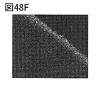
- Figures 48D-48F show the EDX surface analysis results.
- FIG. 49A shows a transmission electron image.
- FIG. 49B shows a Z-contrast image.
- FIG. 49C shows a transmission electron image.
- Figures 49D-49F show the results of EDX surface analysis.
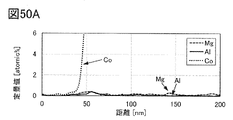
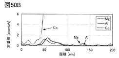
- Figures 50A-50C show the results of EDX-ray analysis.
- FIG. 51 is a flow diagram showing a method of charging a secondary battery.
- FIG. 52 shows the results of cycle characteristics of the secondary battery.
- FIG. 53 shows the relationship between the end-of-charge voltage of the secondary battery and the charge/discharge cycle of the secondary battery.
- 54A to 54C show dQ/dV curves of secondary batteries.
- 55A and 55B show dQ/dV curves of secondary batteries.
- the ordinal numbers “first”, “second”, and “third” are added to avoid confusion of constituent elements. Therefore, the number of components is not limited. Also, the order of the components is not limited. Also, for example, the component referred to as “first” in one of the embodiments of this specification etc. is the component referred to as “second” in another embodiment or the scope of claims It is possible. Further, for example, the component referred to as “first” in one of the embodiments of this specification etc. may be omitted in other embodiments or the scope of claims.
- top views also called “plan views” or perspective views
- descriptions of some components may be omitted in order to make the drawings easier to understand.
- electrode or “wiring” in this specification and the like does not functionally limit these components. For example, it may be used as part of an “electrode” or “wiring” and vice versa. Furthermore, the term “electrode” or “wiring” includes the case where a plurality of “electrodes” or “wiring” are integrally formed.
- terminal may refer to, for example, a wiring or an electrode connected to the wiring.
- part of “wiring” may be referred to as “terminal”.
- electrode B on insulating layer A does not require that electrode B be formed on insulating layer A in direct contact with another configuration between insulating layer A and electrode B. Do not exclude those containing elements.
- the functions of the source and drain are interchanged depending on the operating conditions, such as when using transistors with different polarities or when the direction of the current changes during circuit operation. is difficult. Therefore, the terms source and drain can be used interchangeably in this specification.
- electrically connected includes cases of direct connection and cases of connection via "something that has some electrical effect".
- something that has some kind of electrical action is not particularly limited as long as it enables transmission and reception of electrical signals between connection objects. Therefore, even when it is expressed as “electrically connected", in an actual circuit, there are cases where there is no physical connection part and only the wiring extends.
- parallel means, for example, a state in which two straight lines are arranged at an angle of -10° or more and 10° or less. Therefore, the case of ⁇ 5° or more and 5° or less is also included.
- perpendicular and perpendicular mean, for example, that two straight lines are arranged at an angle of 80° or more and 100° or less. Therefore, the case of 85° or more and 95° or less is also included.
- voltage often indicates a potential difference between a certain potential and a reference potential (eg, ground potential or source potential). Therefore, voltage and potential are often interchangeable.
- semiconductor even if it is described as a "semiconductor”, for example, if the conductivity is sufficiently high, it has the characteristics of a “conductor”. Therefore, “semiconductor” can be replaced with “conductor”. In this case, the boundary between “semiconductor” and “conductor” is ambiguous, and it is difficult to strictly distinguish between the two. Therefore, the terms “semiconductor” and “conductor” described in this specification may be read interchangeably.
- an “on state” of a transistor means a state in which the source and drain of the transistor can be considered to be electrically short-circuited (also referred to as a “conducting state”).
- An “off state” of a transistor means a state in which the source and drain of the transistor can be considered to be electrically cut off (also referred to as “non-conducting state”).
- on current sometimes refers to the current that flows between the source and the drain when the transistor is on.
- off current sometimes refers to a current that flows between a source and a drain when a transistor is in an off state.
- a high power supply potential VDD (hereinafter also simply referred to as “VDD” or “H potential”) indicates a power supply potential higher than the low power supply potential VSS.
- VDD high power supply potential
- VSS low power supply potential
- VDD ground potential
- VSS ground potential
- a gate means part or all of a gate electrode and a gate wiring.
- a gate wiring is a wiring for electrically connecting at least one gate electrode of a transistor to another electrode or another wiring.
- a source refers to part or all of a source region, a source electrode, and a source wiring.
- a source region is a region of a semiconductor layer whose resistivity is equal to or less than a certain value.
- a source electrode refers to a portion of a conductive layer connected to a source region.
- a source wiring is a wiring for electrically connecting at least one source electrode of a transistor to another electrode or another wiring.
- drain refers to part or all of the drain region, the drain electrode, and the drain wiring.
- the drain region means a region of the semiconductor layer whose resistivity is equal to or less than a certain value.
- the drain electrode refers to a portion of the conductive layer connected to the drain region.
- a drain wiring is a wiring for electrically connecting at least one drain electrode of a transistor to another electrode or another wiring.
- segregation refers to a phenomenon in which an element (eg, B) is spatially unevenly distributed in a solid composed of multiple elements (eg, A, B, and C).
- the surface layer portion of a particle such as an active material refers to a region up to about 10 nm vertically or substantially vertically from the surface toward the inside. or a region within 50 nm. or a region within 5 nm.
- Subsurface is synonymous with near-surface, near-surface region or shell.
- substantially perpendicular means 80° or more and 100° or less. Surfaces caused by cracks or cracks may also be referred to as surfaces. A region deeper than the surface layer is called the inside.
- the surface of the positive electrode active material in EDX line analysis or the like is defined as a measurement point where the transition metal shows a measured value closest to 50% of the average value of the detected amount of the bulk.
- the point of intersection of the tangent line drawn to the intensity profile of the EDX ray analysis of the transition metal and the axis in the depth direction by the tangent line method is the boundary between the area where the image derived from the crystal structure of the positive electrode active material is observed and the area where it is not observed, and is derived from the atomic nucleus of a metal element having an atomic number larger than that of lithium. be the outermost region of the region where the atomic columns that Alternatively, it is the intersection of the tangent drawn to the luminance profile from the surface to the bulk of the STEM image and the axis in the depth direction.
- Surfaces in STEM images and the like may be determined in conjunction with higher spatial resolution analysis.
- the layered rock salt type crystal structure of a composite oxide containing lithium and a transition metal has a rock salt type ion arrangement in which cations and anions are alternately arranged, and the transition metal and lithium are A crystal structure in which lithium can diffuse two-dimensionally because it is regularly arranged to form a two-dimensional plane.
- the layered rock salt type crystal structure may be a structure in which the lattice of the rock salt type crystal is distorted.
- a rock salt-type crystal structure refers to a structure in which cations and anions are arranged alternately. In addition, there may be a lack of cations or anions.
- the O3′-type crystal structure (also referred to as a pseudo-spinel-type crystal structure) possessed by a composite oxide containing lithium and a transition metal is a space group R-3m, and is not a spinel-type crystal structure.
- it refers to a crystal structure in which ions of cobalt, magnesium, etc. occupy six oxygen-coordinated positions and the arrangement of cations has a symmetry similar to that of the spinel type.
- a light element such as lithium may occupy four oxygen-coordinated positions, and in this case also, the arrangement of ions has a symmetry similar to that of the spinel type.
- the O3′-type crystal structure is similar to the CdCl 2 -type crystal structure, although it has Li randomly between the layers.
- the crystal structure similar to this CdCl2 type is close to the crystal structure when lithium nickelate is charged to Li0.06NiO2 , but pure lithium cobalt oxide or a layered rock salt type positive electrode active material containing a large amount of cobalt is used. It is known that the crystal does not normally have this crystal structure.
- the anions of layered rock salt crystals and rock salt crystals have a cubic close-packed structure (face-centered cubic lattice structure).
- the O3' type crystal is also presumed to have a cubic close-packed structure of anions. When they meet, there are crystal planes that align the cubic close-packed structure composed of anions.
- the space group of layered rocksalt crystals and O3' crystals is R-3m
- the space group of rocksalt crystals is Fm-3m (the space group of common rocksalt crystals) and Fd-3m (the simplest symmetry). Therefore, the Miller indices of the crystal planes satisfying the above conditions are different between the layered rocksalt crystal and the O3′ crystal, and the rocksalt crystal.
- the cubic close-packed structures composed of anions are oriented in the layered rocksalt-type crystal, the O3′-type crystal, and the rocksalt-type crystal, it is sometimes said that the orientations of the crystals roughly match. be.
- a secondary battery has, for example, a positive electrode and a negative electrode.
- a positive electrode active material is one of the materials that constitute the positive electrode.
- the positive electrode active material is, for example, a material that undergoes a reaction that contributes to charge/discharge capacity.
- the positive electrode active material may partially contain a material that does not contribute to charge/discharge capacity.
- the positive electrode active material used in one aspect of the present invention may be expressed as a positive electrode material, a positive electrode material for a secondary battery, or the like.
- the positive electrode active material used in one embodiment of the present invention preferably contains a compound.
- the positive electrode active material used in one embodiment of the present invention preferably has a composition.
- the positive electrode active material used in one embodiment of the present invention preferably has a composite.
- the Miller index is used to describe crystal planes and crystal orientations. Individual planes indicating crystal planes are indicated using ( ). Crystal planes, crystal orientations, and space groups are indicated by a superscript bar on the number from the standpoint of crystallography. - (minus sign) may be attached and expressed. In addition, individual orientations that indicate directions within the crystal are [ ], collective orientations that indicate all equivalent directions are ⁇ >, individual planes that indicate crystal planes are ( ), and collective planes that have equivalent symmetry are ⁇ ⁇ to express each.
- the trigonal crystal represented by the space group R-3m is generally represented by a composite hexagonal lattice of hexagonal crystals for ease of understanding of the structure, and (hkl) as well as (hkl) is used as the Miller index. There is where i is -(h+k).
- the theoretical capacity of a positive electrode active material refers to the amount of electricity when all the lithium that can be inserted and detached included in the positive electrode active material is desorbed.
- LiCoO 2 has a theoretical capacity of 274 mAh/g
- LiNiO 2 has a theoretical capacity of 274 mAh/g
- LiMn 2 O 4 has a theoretical capacity of 148 mAh/g.
- the depth of charge is a value that indicates how much capacity is charged based on the theoretical capacity of the positive electrode active material, in other words, how much lithium is desorbed from the positive electrode.
- the theoretical capacity is 274 mAh/
- LiCoO2 lithium cobalt oxide
- LiNixCoyMnzO2 ( x + y + z 1)
- LiCoO 2 (0 ⁇ a ⁇ 1) is expressed as LiCoO 2 where a is 1 when the charging depth is 0, and a is 0.5 when the charging depth is 0.5.
- the charging depth is 0.8, it is represented as Li 0.2 CoO 2 with a of 0.2.
- FIG. 1A shows an example of a power storage system 100.
- the power storage system 100 has a charger 101 and a secondary battery 121 .
- Charger 101 is electrically connected to a positive electrode and a negative electrode of secondary battery 121 .
- the charger 101 has a control circuit 153 , a current measurement circuit 152 and a voltage measurement circuit 151 . Moreover, the charger 101 preferably has a temperature sensor TS.
- a temperature sensor TS can measure the ambient temperature of the secondary battery. The temperature sensor TS is set, for example, so as to be in contact with the exterior body or housing of the secondary battery. Control of charging using temperature will be described later.
- the current measurement circuit 152 has a function of measuring the current of the secondary battery 121.
- current measurement circuit 152 preferably has a function of measuring the charging current of secondary battery 121 .
- the current measurement circuit 152 can provide the measured current value to the control circuit 153 .
- the voltage measurement circuit 151 has a function of measuring the voltage of the secondary battery 121.
- voltage measurement circuit 151 preferably has a function of measuring the charging voltage of secondary battery 121 .
- the voltage measurement circuit 151 can provide the measured voltage value to the control circuit 153 .
- the control circuit 153 has a function of controlling the start and stop of charging of the secondary battery 121 . Also, the control circuit 153 has a function of controlling charging conditions of the secondary battery 121 . Specifically, for example, the control circuit 153 has a function of controlling the charging current of the secondary battery 121 .
- control circuit 153 a CPU (Central Processing Unit), MCU (Micro Controller Unit), or the like can be used.
- CPU Central Processing Unit
- MCU Micro Controller Unit
- the control circuit 153 also has a function of calculating the time change of the voltage of the secondary battery 121 given from the voltage measurement circuit 151 .
- Calculation of voltage change over time means, for example, obtaining a plurality of set data of voltage value and time and performing calculation using the obtained plurality of set data. Specifically, for example, it has a function of calculating time differentiation.
- the control circuit 153 preferably has an analog-digital conversion circuit. When the secondary battery voltage value obtained is an analog value, the control circuit 153 can convert it into a digital value using an analog-digital conversion circuit.
- the control circuit 153 may be configured to include the voltage measurement circuit 151 and the analog-digital conversion circuit section. Also, the analog-digital conversion circuit may be prepared separately from the control circuit 153 .
- control circuit 153 uses the voltage value of the secondary battery 121 given from the voltage measurement circuit 151 and the current value of the secondary battery 121 given from the current measurement circuit 152 to calculate the electric quantity of the secondary battery. It has the function to The control circuit 153 also has a function of calculating the voltage differential (dQ/dV) of the electric quantity of the secondary battery.
- control circuit 153 has a memory circuit.
- the memory circuit functions as a register of CPU or MCU, or as a cache memory, for example.
- the storage circuit has a function of holding various programs used in the power storage system 100 and data necessary for operating the power storage system 100, for example.
- FIG. 1B shows an example in which charger 101 has detection circuit 185, detection circuit 186, short detection circuit SD, micro-short detection circuit MSD, transistor 140 and transistor 150 in addition to the configuration shown in FIG. 1A. Details of the detection circuit 185, the detection circuit 186, the short detection circuit SD, the micro-short detection circuit MSD, the transistor 140 and the transistor 150 will be described later.
- the current measurement circuit 152 has, for example, a resistive element.
- 2A and 2B show an example where the current measurement circuit 152 has a resistive element 152a and a circuit 152b.
- the resistance element 152a functions as a shunt resistor.
- the circuit 152b has the function of measuring the voltage across the resistive element 152a.
- the power storage system 100 may also have a DC-DC converter 157 as shown in FIGS. 3A and 3B.
- the DC-DC converter 157 has a voltage conversion circuit and a control circuit.
- the DC-DC converter 157 has a function of converting the voltage of the secondary battery 121 and outputting it.
- the power storage system 100 may also have a circuit 158 as shown in FIGS. 3A and 3B.
- Circuit 158 preferably functions as an AC adapter.
- Circuit 158 for example, has the function of converting AC power to DC power.
- the circuit 158 may have a function of converting a voltage, for example.
- the circuit 158 has a function of supplying the secondary battery with power converted into direct current.
- the circuit 158 may have a function of controlling the applied current value and the applied voltage value when power is applied to the secondary battery.
- the circuit 158 may have a function of controlling the current value and the voltage value to be applied to the secondary battery based on the signal provided from the control circuit 153 .
- a diode 159 may be provided between the circuit 158 and the charger 101, as shown in FIGS. 3A and 3B. Diode 159 has the function of suppressing reverse current from charger 101 to circuit 158 .
- the charging depth of the secondary battery is deepened, and the change in the crystal structure is in a substantially reversible range. It is required to keep the charging depth of
- the charging depth of the secondary battery can be kept so that the change in the crystal structure is substantially reversible.
- the charging depth of the secondary battery increases as the charging/discharging cycle increases. It becomes difficult to be the same. Therefore, in order to keep the charging depth of the secondary battery within the range where the crystal structure is approximately reversible, means for monitoring the charging process is required.
- the charging process can be monitored, and the charging depth of the secondary battery can be kept within a range where the charging depth is deep and the crystal structure is substantially reversible.
- the positive electrode active material of one embodiment of the present invention is preferably applied to the secondary battery.
- the charger of one embodiment of the present invention can suppress collapse of the crystal structure of the positive electrode active material of the secondary battery by controlling the charging conditions of the secondary battery. More specifically, for example, the charger of one embodiment of the present invention can maximize the charging voltage of the secondary battery within a range in which the collapse of the crystal structure can be suppressed, thereby improving the reliability of the secondary battery. , high energy density can be realized by marginal utilization of secondary batteries.
- a positive electrode active material having a layered crystal structure for example, metals serving as carrier ions are arranged in layers.
- metals serving as carrier ions are arranged in layers.
- lithium cobaltate lithium is layered between CoO 2 layers.
- crystal distortion, change in crystal structure due to carrier ion detachment, and the like may occur when carrier ions are desorbed during charging.
- lithium cobalt oxide changes such as displacement of the CoO 2 layer and shrinkage of the interlayer distance of the CoO 2 layer may occur when lithium ions are desorbed during charging.
- an excessively high charging voltage may cause elution of constituent elements of the positive electrode active material into the electrolytic solution, leading to collapse of the crystal structure of the positive electrode active material.
- charging at a high voltage may cause a decomposition reaction or the like of the elements that make up the electrolyte.
- the charger of one embodiment of the present invention uses a simple method to detect changes in the crystal structure, increase the charging voltage to the limit within a range in which high reliability can be ensured, and increase the charge/discharge capacity of the secondary battery to the limit. It can be used efficiently.
- the secondary battery 121 to which the charger of one embodiment of the present invention is applied is preferably a secondary battery whose upper limit voltage for charging can be determined from a waveform obtained during charging.
- the waveform can have various shapes such as a curved line, a straight line, and a combination of a curved line and a straight line.
- the waveform is not limited to periodic waves. Examples of waveforms obtained during charging include a dQ/dV-V curve or a ⁇ V-t curve created from data on voltage, time, and current during charging. That is, it is preferable that the secondary battery 121 detects an extreme value due to a change in the crystal structure of the positive electrode active material in the waveform obtained during charging.
- the charging voltage in repeated charging and discharging is preferably increased to the limit, and even at the increased charging voltage, the change in the crystal structure of the positive electrode active material is approximately reversible.
- the term “substantially reversible” means that deterioration due to repeated changes in crystal structure is extremely small even in the case of being reversible or irreversible.
- the positive electrode active material of one embodiment of the present invention changes from an O3-type crystal structure to an O3′-type crystal structure, which will be described later, when the SOC (State of Charge) of the secondary battery is about 80% or in the vicinity thereof. Also, when this change occurs, extreme values are observed in the dQ/dV curve and the like.
- a charger of one embodiment of the present invention has a function of detecting this extreme value and controlling charging.
- the extreme value due to the change in the crystal structure in the secondary battery 121 must be the upper limit of charging. It is preferably in the vicinity of the voltage. For example, it is preferable that the peak due to the change in crystal structure is lower than the upper limit voltage for charging, and the difference between the voltage at which the above extreme value is detected and the upper limit voltage for charging is 0.15 V or less.
- the crystal structure of the positive electrode active material can substantially reversibly change during charging and discharging even after charging for a predetermined time at a voltage exceeding the voltage at which the extreme value is detected. Since the secondary battery 121 has such characteristics, the charger of one embodiment of the present invention can easily control the upper limit voltage of charging for marginal use using the above extreme value.
- the extreme value resulting from the change in the crystal structure is detected, for example, in the time change curve of the voltage of the secondary battery. Alternatively, it is detected in the time differential curve (dV/dt curve) of the voltage of the secondary battery.
- extreme values resulting from changes in the crystal structure are detected, for example, in the voltage differential curve (dQ/dV curve) of the electric quantity of the secondary battery.
- CC-CV charging constant current-constant voltage charging
- constant current charging is performed, and after reaching the upper limit voltage of charging in constant current charging, constant voltage charging is performed.
- CC-CV charging for example, by performing constant voltage charging at the upper limit voltage of constant current charging, charging can be performed over time at the upper limit voltage, and the charging capacity is reduced by the change in impedance due to deterioration of the secondary battery. It is possible to obtain a charge capacity with little variation.
- the charging capacity can be increased.
- charging at a high voltage may lead to collapse of the crystal structure of the positive electrode active material, decomposition reaction of elements constituting the electrolyte, and the like. Therefore, there is a concern that constant voltage charging at the upper limit voltage will increase the deterioration of the secondary battery.
- the charging time at the upper limit voltage can be reduced and the life of the secondary battery can be lengthened, which is preferable. In particular, under high-temperature conditions where the ambient temperature of the secondary battery exceeds 40° C., the secondary battery may significantly deteriorate in constant-voltage charging at the upper limit voltage.
- the environmental temperature of the secondary battery when the environmental temperature of the secondary battery is high, it is more preferable to perform constant current charging. Moreover, when the environmental temperature of the secondary battery is high, it is preferable not to use constant voltage charging at a high voltage, or to shorten the time of constant voltage charging at a high voltage as much as possible.
- a positive electrode active material represented by the chemical formula AM y O Z (y>0, z>0)
- a positive electrode active material represented by the chemical formula AMO 2 will be described.
- the details of the positive electrode active material represented by the chemical formula AM y O Z (y>0, z>0), as well as the element A and the metal M will be described later.
- the positive electrode active material is represented by the chemical formula AMO 2
- the composition of A:M:O is not limited to 1:1:2.
- Lithium cobalt oxide may also be represented as LiCoO 2 .
- Lithium nickelate may also be expressed as LiNiO 2 .
- the state of charge (SOC) is 85% or less, 80% or less, or 77% or less. Charge the next battery.
- the degree of charge can be expressed by using x in the composition formula, for example, x in Li x CoO 2 , to indicate how much lithium that can be intercalated and deintercalated remains in the positive electrode active material.
- x (theoretical capacity ⁇ charge capacity)/theoretical capacity.
- LiCoO 2 LiCoO 2
- x 0.2.
- a small x in Li x CoO 2 means, for example, 0.1 ⁇ x ⁇ 0.24.
- charging may be performed so that x is 0.2 or less, 0.24 or less, or 0.3 or less.
- the theoretical capacity of the positive electrode active material refers to the amount of electricity when all of the lithium that can be inserted and detached included in the positive electrode active material is desorbed.
- LiCoO 2 has a theoretical capacity of 274 mAh/g
- LiNiO 2 has a theoretical capacity of 274 mAh/g
- LiMn 2 O 4 has a theoretical capacity of 148 mAh/g.
- the charge capacity and/or discharge capacity used to calculate x in Li x CoO 2 is preferably measured under conditions where there is no or little influence of short circuit and/or decomposition of the electrolyte.
- the data of a secondary battery in which a sudden change in capacity, which is thought to be caused by a short circuit, has occurred should not be used for calculating x.
- the upper limit voltage for charging is preferably 4.8 V or lower, more preferably 4.8 V or lower, more preferably 4 V, based on the lithium potential (Li/Li + ).
- the battery is charged to 0.75 V or less, more preferably 4.7 V or less, more preferably 4.65 V or less.
- the charge rate (also referred to as C rate, capacity rate) is preferably 0.35 C or higher, more preferably 0.45 C or higher, and further preferably 0.
- the battery is charged to 0.9C or more, preferably 0.9C or more.
- C is the unit of rate.
- charging is performed at a voltage at which the potential of the positive electrode is 4.2 V or higher, 4.3 V or higher, or 4.4 V or higher with respect to the lithium potential (Li/Li + ), so that the charging rate is achieved. conduct.
- the charging rate 1C is, for example, an amount of electricity about 0.7 times the amount of electricity for charging and reacting the total amount of element A (in the case of lithium cobaltate, element A is lithium) of the positive electrode active material. is the current density for charging in one hour.
- the charging depth is preferably 50% or more, more preferably 60% or more, still more preferably 70% or more, and even more preferably 73% or more. Also, the charging depth may be higher than 75%.
- the method of calculating the SOC of the secondary battery is not limited to the example shown above.
- the standardization of the capacitance used for the SOC is not limited to the example shown above. Standards using the volume of a secondary battery, the internal volume of a secondary battery, the volume of a portion of a secondary battery, the weight of a secondary battery, the weight of the contents of a secondary battery, or the weight of a portion of a secondary battery may be changed.
- constant current charging can be performed by detecting an extreme value due to a change in the crystal structure of the positive electrode active material in a dQ/dV curve or the like. Also, the constant current charging using the detection of the extreme value is simple and has good controllability. Therefore, by using the charger of one embodiment of the present invention, a secondary battery in which variation in charge capacity is small and deterioration due to high-voltage charging is suppressed can be achieved.
- the details of the secondary battery that can be used as the secondary battery 121 will be described later.
- the voltage measurement circuit 151 measures the voltage Vb1 between the positive electrode and the negative electrode of the secondary battery as shown in FIG. 4A, and measures the voltage obtained by dividing the voltage Vb1 by resistance as shown in FIG. 4B.
- the voltage of the secondary battery refers to, for example, the voltage between the positive electrode and the negative electrode of the secondary battery.
- voltage measurement circuit 151 divides voltage Vb1 into voltage Vb2 and voltage Vb3 by resistance element 122 and resistance element 123, and measures voltage Vb3.
- the voltage measurement circuit 151 measures the voltage obtained by resistance-dividing the voltage between the positive electrode and the negative electrode of the secondary battery
- the voltage measurement circuit 151 or the control circuit 153 measures the secondary battery voltage from the resistance-divided voltage. may estimate the voltage between the positive and negative electrodes of
- the charger of one embodiment of the present invention preferably functions as a coulomb counter.
- the charger of one embodiment of the present invention calculates the charge capacity and discharge capacity of the secondary battery by calculating the integrated charge amount of the secondary battery 121 using the current measurement circuit 152 and the control circuit 153. It has the function to Further, the charger of one embodiment of the present invention may have a function of analyzing the state of charge (SOC) using the calculated charge capacity and discharge capacity.
- SOC state of charge
- step S100 processing is started.
- step S101 constant current charging of the secondary battery is started at time t1. Note that the constant current charging is continuously performed until the charging is stopped in step S107.
- step S102 the voltage measurement circuit 151 starts measuring the voltage of the secondary battery. Also, the current measurement circuit 152 starts measuring the current of the secondary battery. Voltage measurement circuit 151 provides the measured voltage value to control circuit 153 . Current measurement circuit 152 provides the measured current value to control circuit 153 .
- step S103 after step S102, the control circuit 153 accumulates the voltage value measured by the voltage measurement circuit 151 and the current value measured by the current measurement circuit 152 as paired data with time.
- a memory circuit or the like included in the control circuit 153 can be used for data accumulation.
- the time from the start of charging may be used as the time associated with the voltage value and the current value.
- step S104 the control circuit 153 calculates a voltage differential curve (dQ/dV curve) of the electric quantity of the secondary battery using the set data of the voltage value, the current value, and the time accumulated as needed.
- the voltage differential curve of the electric quantity of the secondary battery may be calculated after accumulating the set data of the voltage value, the current value and the time for a predetermined time. For example, tuple data may be accumulated for a period of time sufficient to detect extreme values.
- step S105 the control circuit 153 analyzes a curve (hereinafter referred to as a dQ/dV-V curve) in which the horizontal axis is the voltage V and the vertical axis is the voltage differential dQ/dV of the quantity of electricity Q, and makes a determination. . If an extreme value (also referred to as a peak) is detected in the dQ/dV-V curve, for example, a maximum (also referred to as an upwardly convex peak) is detected here, the process proceeds to step S106. If not detected, the process returns to step S103.
- a plurality of extreme values may be detected in the dQ/dV-V curve. In such a case, the highest extreme value is detected among the multiple extreme values. Alternatively, the top r extreme values (r is an integer equal to or greater than 2) may be detected from a plurality of extreme values, and one of the r extreme values may be selected.
- the upper extreme value refers to the higher one among the rankings determined based on the specified conditions.
- the height of the extreme value may be in descending order.
- control circuit 153 continuously accumulates the set data of the voltage value, the current value and the time while repeating the steps from step S103 to step S105. That is, when the steps from step S103 to step S105 are repeated n times, the dQ/dV-V curve can be calculated using all the data of n times. Alternatively, out of n times, only the latest one or only the latest several times may be used.
- step S106 when the voltage V of the secondary battery is equal to or higher than the voltage V2, the process proceeds to step S107.
- the voltage V2 is, for example, 4.25V or more, or 4.25 or more and less than 4.8V.
- step S006 may be made based on the charging depth of the secondary battery. For example, when the charge depth of the secondary battery is S1% or more, the process proceeds to step S007, and when it is less than S1%, the process returns to step S003.
- S1 is 60[%] or more, or 60[%] or more and 95[%] or less.
- the control circuit 153 can continuously accumulate the set data of the voltage value, the current value, and the time from the first step S103 of the multiple repeated steps S103 to step S107.
- step S107 the time tp at which the dQ/dV-V curve takes an extreme value is detected by analysis, and charging is stopped at time t2, which is a time after a predetermined time has passed from time tp.
- the predetermined time is, for example, the time required for the control circuit 153 to stop charging.
- time t2 for example, in the dQ/dV-V curve, a region having a desired voltage width is determined centering on the voltage having the extreme value, and the time corresponding to the voltage at the upper end of the region is defined as time t2. may If no extreme value is detected in step S107, charging may be stopped when a predetermined charging voltage is reached.
- a moving average may be used as a smoothing method.
- the inflection point detected at time tp is, for example, an inflection point caused by a change in the crystal structure of the positive electrode active material of the positive electrode of the secondary battery.
- the positive electrode active material of one embodiment of the present invention as the positive electrode active material, if charging of the secondary battery is stopped at a time near time tp, the crystal structure of the positive electrode active material changes due to repeated charging and discharging. collapse can be suppressed.
- the positive electrode active material of one embodiment of the present invention is used so that the crystal structure of the positive electrode active material changes from an O3-type crystal structure to an O3′-type crystal structure.
- the positive electrode active material is, for example, lithium cobalt oxide.
- the charging voltage or the charging depth at time t2 is preferably lower than the charging voltage at which the crystal structure of the positive electrode active material changes to the H1-3 type crystal structure, or shallower than the charging depth. Details of the O3-type crystal structure, the O3′-type crystal structure, and the H1-3-type crystal structure will be described later.
- the change from the O3-type crystal structure to the O3'-type crystal structure may be expressed as a phase change.
- the crystal structure at time t2 can be controlled to be the O3' type crystal structure. This can prevent the crystal structure of the positive electrode active material from collapsing due to repeated charging and discharging of the secondary battery.
- the determined crystal structure is represented by the space group R-3m. It is further preferred that the determined crystal structure is represented by the space group R-3m and suggests an O3'-type crystal structure.
- a positive electrode obtained by disassembling a secondary battery that has been charged by the power storage system of one embodiment of the present invention in a charged state corresponding to time t2 is evaluated by X-ray diffraction, it corresponds to the space group R-3m. A spectrum is observed.
- the measurement conditions, the measurement method, and the like the description given below can be referred to.
- the determined crystal structure is represented by the space group R-3m.
- the positive electrode when the positive electrode is analyzed by X-ray diffraction at time t2 and before charging, the determined crystal structure is represented by the space group R-3m.
- a secondary battery can be obtained in which the discharge capacity decreases little during cycles.
- s is an integer of 2 or more.
- the time tp and time t2 obtained based on the extreme values detected in steps S102 to S106 may be used in the next charging cycle.
- the time tp and the time t2 obtained in the (s ⁇ 1)th charge may be used as conditions for stopping the charge in step S107 of the sth charge.
- step S199 the process ends.
- the current value of the constant-current charging is set as a constant current value, for example, from when charging is started in step S101 to when charging is stopped in step S107.
- the current value in constant-current charging may be changed stepwise from when charging is started in step S101 to when charging is stopped in step S107.
- the current value may be changed after a certain number of times.
- the charger of one embodiment of the present invention can perform charging characteristics of the secondary battery in steps S103 to S106, and change the charging condition of the secondary battery in step S107 according to the analysis results. Specifically, for example, charging of the secondary battery can be stopped.
- the charging characteristics analyzed in steps S103 to S106 change according to the environmental temperature of charging/discharging of the secondary battery, deterioration of the secondary battery due to charging/discharging cycles, and the like.
- the charger of one embodiment of the present invention suppresses deterioration of the secondary battery by changing the charging conditions of the secondary battery, for example, the charging voltage of the secondary battery, in accordance with such changes in charging characteristics. be able to.
- the charging characteristics of the charger of one embodiment of the present invention are analyzed, so that the secondary battery can be charged to the limit within a range in which deterioration of the secondary battery is suppressed.
- step S107 after time t4, constant voltage charging may be performed at a voltage lower than the upper limit charging voltage for constant current charging at time t4.
- Example 2 of charging method> An example of a charging method using the charger of one embodiment of the present invention will be described with reference to the flow diagram in FIG.
- the calculation performed by the control circuit 153 is simpler than in the charging method shown in FIG. 5, and can be performed in a smaller circuit scale.
- dQ/dV can be expressed as in the following formula.
- dQ/dt is constant during constant current charging
- dQ/dV is proportional to dt/dV. Therefore, by evaluating the dt/dV characteristics during constant current charging, information similar to the dQ/dV characteristics can be obtained.
- dQ/dV in constant current charging may change more slowly than dQ/dV in constant voltage charging.
- step S000 processing is started.
- step S001 constant current charging of the secondary battery is started at time t3. Note that the constant current charging is continuously performed until the charging is stopped in step S007.
- step S002 the voltage measurement circuit 151 starts measuring the voltage of the secondary battery.
- Voltage measurement circuit 151 provides the measured voltage value to control circuit 153 .
- step S003 after step S002, the control circuit 153 accumulates the voltage values measured by the voltage measurement circuit 151 as paired data with time.
- a memory circuit or the like included in the control circuit 153 can be used for data accumulation.
- the time from the start of charging may be used as the time associated with the voltage value.
- the obtained voltage value is converted from an analog value to a digital value in the control circuit 153 .
- the control circuit 153 may use the acquired analog values for calculation without converting them into digital values.
- an MCU is used as the control circuit 153 and a voltage value is converted using an analog-digital conversion circuit mounted on the MCU will be described.
- an MCU equipped with an analog-digital conversion circuit with 12-bit voltage resolution is used.
- the predetermined value can be, for example, the minimum value of the voltage resolution of the analog-to-digital conversion circuit, or a value greater than that.
- the change in voltage value or the absolute value of the change in voltage value is less than a predetermined value, after a predetermined time has passed since the acquisition of the previous group data, the group data of voltage value and time is acquired and stored. do.
- step S004 the control circuit 153 uses the set data of the voltage value and the time accumulated as needed to calculate the time change of the voltage of the secondary battery.
- the change in voltage over time is expressed as voltage [V(t)-V(t- ⁇ t1)] using voltage V(t) at time t and voltage V(t- ⁇ t1) at time (t- ⁇ t1).
- a curve of voltage change over time may be referred to as a ⁇ Vt curve.
- time differentiation of voltage (dV/dt) may be used as the time change of voltage.
- the time change may be calculated after accumulating set data of the voltage value and the time for a predetermined time. For example, tuple data may be accumulated for a period of time sufficient to detect extreme values.
- step S005 the control circuit 153 analyzes the time change curve (eg, ⁇ V-t curve) of the voltage of the secondary battery and makes a determination. If an extreme value, for example a minimum (also referred to as a downwardly convex peak) is detected in the time change curve, the process proceeds to step S006. If not detected, the process returns to step S003.
- a plurality of extreme values may be detected in the ⁇ V-t curve. In such a case, the highest extreme value is detected among the multiple extreme values.
- the top r extreme values (r is an integer equal to or greater than 2) may be detected from among a plurality of extreme values, and one of the r extreme values may be selected.
- control circuit 153 continuously accumulate the set data of the voltage value and the time while repeating the steps from step S003 to step S005. That is, when the steps from step S003 to step S005 are repeated n times, the time change curve can be calculated using all the data of n times. Alternatively, out of n times, only the latest one or only the latest several times may be used. Here, n is an integer of 1 or more.
- step S006 the control circuit 153 makes a determination based on the voltage of the secondary battery.
- the process proceeds to step S007.
- the voltage V1 is, for example, 4.25V or more, or 4.25V or more and less than 4.8V.
- the voltage measurement circuit 151 measures the voltage obtained by resistance-dividing the voltage between the positive and negative electrodes of the secondary battery
- the voltage V1 is the voltage estimated from the resistance-divided voltage of the secondary battery. It is preferred to use an estimate of the voltage between the positive and negative electrodes of
- step S006 may be made based on the charging depth of the secondary battery. For example, when the charge depth of the secondary battery is S1% or more, the process proceeds to step S007, and when it is less than S1%, the process returns to step S003.
- S1 is 60[%] or more, or 60[%] or more and 95[%] or less.
- the control circuit 153 can continuously accumulate the set data of the voltage value and the time from the first step S003 of the multiple repeated steps S003 to step S007.
- step S007 time tq at which the ⁇ V-t curve takes an extreme value is detected by analysis, and charging is stopped at time t4, which is a time after a predetermined time has passed from time tq.
- time t4 for example, in the ⁇ V-t curve, a region having a desired time width centered on the time when the extreme value is obtained may be determined, and the time at the upper end of the region may be determined as time t4.
- the predetermined time is, for example, the time required for the control circuit 153 to stop charging. If no extreme value is detected in step S007, charging may be stopped when a predetermined charging voltage is reached.
- w is an integer of 2 or more.
- the times t3 and t4 obtained based on the extreme values detected in steps S002 to S006 may be used in the next charging cycle.
- the time tq and the time t4 obtained in the (w ⁇ 1)-th charge may be used as conditions for stopping charging in step S007 of the w-th charge.
- step S099 the process ends.
- the current value of the constant-current charging is set as a constant current value, for example, from when charging is started in step S001 until charging is stopped in step S007.
- the current value in constant-current charging may be changed stepwise from when charging is started in step S001 to when charging is stopped in step S007.
- steps S003 to S005 are repeated n times, the current value may be changed after a certain number of times.
- step S000 processing is started.
- step S001 constant current charging of the secondary battery is started. Note that the constant current charging is continuously performed until the charging is stopped in step S006.
- step S002 the voltage measurement circuit 151 starts measuring the voltage of the secondary battery. Measured voltage V is applied from voltage measurement circuit 151 to control circuit 153 .
- step S003 the control circuit 153 compares the measured voltage V with a predetermined voltage V1. If the voltage V is equal to or higher than the voltage V1, the process proceeds to step S004, and if the voltage V is lower than the voltage V1, the process returns to step S002.
- the control circuit 153 evaluates dQ/dV.
- the value of dt/dV is measured.
- the value of dt/dV can be accumulated at any time during the charging process.
- a moving average [dt/dV]mean of dt/dV and a maximum value [dt/dV]max are calculated using the accumulated set data of voltage V and time t.
- the time required for the voltage to change by a predetermined value may be calculated.
- the predetermined value may be, for example, 0.5 mV or more and 10 mV or less.
- step S005 the moving average [dt/dV]mean is compared with a value obtained by multiplying the maximum value [dt/dV]max by a constant Rt. If the moving average [dt/dV]mean is smaller than the maximum value [dt/dV]max multiplied by the constant Rt, the process proceeds to step S006. If the moving average [dt/dV]mean is equal to or greater than the maximum value [dt/dV]max multiplied by the constant Rt, the process returns to step S004.
- the time when the moving average [dt/dV] mean becomes smaller than the value obtained by multiplying the maximum value [dt/dV]max by the constant Rt is, for example, in the dt/dV curve, from the maximum value near the voltage V1, It corresponds to the time when it has decreased to the maximum value (Rt ⁇ 100) [%].
- Rt is, for example, 0.6 or more and 0.9 or less.
- the change in the crystal structure of the positive electrode active material can be detected, and the change in the crystal structure of the charged positive electrode active material can be detected within a substantially reversible range.
- step S006 charging of the secondary battery is stopped.
- step S099 the process ends.
- the flowchart shown in FIG. 51 shows an example of constant current charging. / dV]max multiplied by a constant Rt, instead of comparing the average value of the electric quantity Q at the measurement time and the time in the vicinity thereof, and the value obtained by multiplying the maximum electric quantity Q by a constant. Just compare.
- the charger of one embodiment of the present invention preferably has a function of estimating the state of health (SOH) of the secondary battery.
- SOH is an index representing the fully chargeable capacity at a certain point in time, based on the fully chargeable capacity in a brand new state.
- SOH is a numerical value expressed as a value smaller than 100 as the deterioration of the secondary battery progresses, with the fully chargeable capacity of a new secondary battery being 100, and the unit is "%".
- the intensity of the extreme values may decrease. This decrease in strength may be due to a phase change corresponding to the extreme value being less likely to occur in the positive electrode active material, and may have a correlation with SOH, for example.
- the charger of one embodiment of the present invention preferably has a function of estimating SOH by observing the intensity of extreme values of the dQ/dV-V curve.
- the voltage at which the extreme value is correlated with the full discharge capacity after charging may have
- the charger of one embodiment of the present invention preferably has a function of estimating the dischargeable capacity of the secondary battery by observing the strength of the extreme value of the dQ/dV-V curve.
- the charger 101 preferably controls charging using temperature.
- the control circuit 153 preferably changes the charging conditions according to the ambient temperature of the secondary battery measured by the temperature sensor TS.
- the storage circuit of the control circuit 153 preferably has, for example, a table in which the environmental temperature of the secondary battery and the charging conditions are linked.
- the storage circuit of the control circuit 153 stores the charging characteristics associated with the environmental temperature of the secondary battery.
- the charge characteristic may be a past measurement value of the secondary battery 121, a measurement value of another secondary battery having similar characteristics, or a waveform obtained by calculation. good too.
- these measured values may be used to estimate extreme values (peaks). For example, machine learning or the like can be used for the estimation.
- the control circuit 153 may use the charging characteristics of the secondary battery stored in the storage circuit for the analysis of extreme values in the differential curves of the voltage and quantity of electricity.
- a capacity-voltage curve, a voltage-dQ/dV curve, a ⁇ V-t curve, impedance characteristics, and the like can be used as charging characteristics.
- FIG. 1B shows that, in addition to the configuration of charger 101 shown in FIG. An example with detection circuit SD, micro-short detection circuit MSD, transistor 140 and transistor 150 is shown.
- the charger 101 shown in FIG. 1B has a function of suppressing overcharge, overdischarge, charge overcurrent, discharge overcurrent, short circuit, micro short circuit, etc., and can function as a secondary battery protection circuit.
- a micro-short refers to a minute short-circuit inside a secondary battery. It is not so short-circuited that the positive and negative electrodes of the secondary battery become unchargeable. refers to a phenomenon in which A large voltage change may occur in a relatively short time and even at a small location.
- Transistors called power MOSFETs can be used as the transistors 140 and 150 .
- the control circuit 153 has a function of cutting off the current flowing through the secondary battery 121 by applying signals to the gates of the transistors 140 and 150 respectively.
- the detection circuit 185 monitors the voltage of the secondary battery, and upon detecting overcharge or overdischarge, can give a signal indicating the detection to the control circuit 153 .
- the control circuit can receive the signal and apply a signal to at least one of the gate of transistor 140 and the gate of transistor 150 to cut off current flowing to secondary battery 121 .
- the detection circuit 186 monitors the current of the secondary battery 121, and when detecting overcurrent during charging or discharging, can give a signal indicating the detection to the control circuit 153.
- the control circuit can receive the signal and apply a signal to at least one of the gate of transistor 140 and the gate of transistor 150 to cut off current flowing to secondary battery 121 .
- the overcharge detected by the detection circuit 185 is the extreme value of the above-described charge voltage time change curve (for example, the ⁇ V-t curve) or the extreme value of the voltage differential curve (dQ/dV curve) of the charged quantity of electricity. may be detected using Alternatively, the overcharge detected by the detection circuit 185 may be detected by using a comparison circuit to compare with a predetermined voltage value. Different values may be used as the predetermined voltage value depending on the environmental temperature of the secondary battery. The voltage value corresponding to the environmental temperature of the secondary battery is stored, for example, in a storage circuit included in the control circuit 153 .
- FIGS. 7A, 7B, and 7C shows an example in which a charger 101 is connected to each of m secondary batteries 121 connected in series.
- FIG. 7A shows an example of a power storage system 100 in which m is an integer of 4 or more, and two of the m secondary batteries 121 are the first, second, third, and m-th secondary batteries 121 . Secondary battery 121(1), secondary battery 121(2), secondary battery 121(3), and secondary battery 121(m) are illustrated, and other secondary batteries are omitted.
- 7B shows an example of the power storage system 100 when m is 3
- FIG. 7C shows an example of the power storage system 100 when m is 2. As shown in FIG.
- the detection circuit 185 included in the charger 101 has a terminal 124 electrically connected to the positive electrode of the secondary battery 121(1) and a terminal 125 electrically connected to the negative electrode of the secondary battery 121(m). Overcharge may be detected at voltages between . Further, for example, the detection circuit 186 and the short detection circuit SD included in the charger 101 may detect overcharge or short circuit based on the current between the terminals 124 and 125 .
- the power storage system 100 can independently control the m secondary batteries 121 (121(1) to 121(m)) using the chargers 101 connected to each.
- the secondary battery 121 that is to be charged first has a path connected in parallel to the secondary battery 121 after charging is completed. is made to flow through a transistor, resistor element, diode, or the like connected to . Therefore, it is preferable that the charger 101 has a secondary battery 121 as a current path and a switch that switches between the path.
- the power storage system 100 has a total voltage of the m secondary batteries (for example, in FIG. 7A, the positive electrode of the secondary battery 121(1) and the secondary The voltage between the negative electrodes of the battery 121(m))) may be used to control charging.
- a total voltage of the m secondary batteries for example, in FIG. 7A, the positive electrode of the secondary battery 121(1) and the secondary The voltage between the negative electrodes of the battery 121(m))
- an m-fold voltage value can be used as the voltage used for charging control.
- a secondary battery of one embodiment of the present invention preferably includes a positive electrode, a negative electrode, and an electrolyte.
- a positive electrode of one embodiment of the present invention includes a positive electrode active material.
- a compound containing a metal M is preferably used as the positive electrode active material.
- a transition metal can be used as the metal M, for example.
- an element that does not change in valence and can have the same valence as the metal M more specifically, for example, a trivalent typical element may be included.
- metal M that can be used include cobalt, nickel, manganese, iron, vanadium, chromium, niobium, and aluminum.
- the positive electrode active material of one embodiment of the present invention contains, for example, one or more of cobalt, nickel, and manganese as the metal M, and particularly contains cobalt.
- sulfur may be used.
- compounds that can be used include oxides, fluorides, sulfides, phosphates, sulfates, borates, silicates, fluorophosphates, fluorosulfates, and the like.
- the positive electrode active material preferably contains the element A in addition to the metal M described above.
- the element A for example, one or more elements selected from alkali metals such as lithium, sodium and potassium, and Group 2 elements such as calcium, beryllium and magnesium can be used.
- Element A is preferably an element that functions as a carrier metal. During charging and discharging of the secondary battery of one embodiment of the present invention, the element A is desorbed from the positive electrode active material and the element A is inserted into the positive electrode active material.
- a layered rock salt crystal structure can be used as the positive electrode active material.
- a composite oxide or the like having a spinel-type crystal structure can be used.
- a polyanion-based positive electrode material can be used as the positive electrode active material. Examples of polyanionic positive electrode materials include materials having an olivine-type crystal structure, Nasicon-type materials, and the like.
- a positive electrode active material of one embodiment of the present invention may be represented by a chemical formula AM y O Z (y>0, z>0). More specifically, for example, the positive electrode active material of one embodiment of the present invention may be represented by the chemical formula AMO2 . Also, although it is written as AMO 2 , the composition of A:M:O is not limited to 1:1:2. Lithium cobaltate is sometimes represented as LiCoO2 . Lithium nickel oxide may also be expressed as LiNiO 2 .
- the positive electrode active material of one embodiment of the present invention preferably contains the element X.
- element X elements such as magnesium, calcium, barium, zirconium, lanthanum, titanium, and yttrium can be used.
- element X elements such as nickel, aluminum, manganese, cobalt, vanadium, iron, chromium, and niobium can be used.
- Elements such as potassium, sodium, copper, zinc, chlorine, fluorine, hafnium, silicon, sulfur, phosphorus, boron, and arsenic can be used as the element X, for example.
- the element X two or more of the elements shown above may be used in combination.
- the element X one or more selected from magnesium, calcium and barium and one or more selected from nickel, aluminum and manganese can be used.
- element X may be substituted at the position of element A.
- the element X may be partially substituted at the metal M position, for example.
- the concentration of element X in the surface layer may be higher than the concentration of element X in the interior. Further, in the positive electrode active material of one embodiment of the present invention, the element X may be uniformly dissolved in the entire positive electrode active material.
- the positive electrode active material of one embodiment of the present invention may be represented by the chemical formula A1 -wXwMyOZ ( y >0, z >0, 0 ⁇ w ⁇ 1). Further, the positive electrode active material of one embodiment of the present invention may be represented by the chemical formula AM y ⁇ j X j O Z (y>0, z>0, 0 ⁇ j ⁇ y). Further, the positive electrode active material of one embodiment of the present invention has a chemical formula of A1 -wXwMy- jXjOZ ( y>0, z >0, 0 ⁇ w ⁇ 1, 0 ⁇ j ⁇ y). may be represented.
- the positive electrode active material of one embodiment of the present invention preferably contains halogen. It is preferable to have halogen such as fluorine and chlorine. When the positive electrode active material of one embodiment of the present invention contains the halogen, the substitution of the element A with the element X may be promoted.
- FIG. 8A is a cross-sectional view of a positive electrode active material 200 that can be used for the secondary battery of one embodiment of the present invention.
- 8B and 8C show enlarged views of the vicinity of AB in FIG. 8A.
- FIGS. 8C and 8D show enlarged views of the vicinity of CD in FIG. 8A.
- the positive electrode active material 200 has a surface layer portion 200a and an inner portion 200b.
- the dashed line indicates the boundary between the surface layer portion 200a and the inner portion 200b.
- part of the grain boundary 201 is indicated by a dashed line in FIG. 8A.
- a region of up to 10 nm from the surface of the positive electrode active material toward the inside is called a surface layer portion 200a.
- Surfaces caused by cracks and/or cracks may also be referred to as surfaces.
- the surface layer portion 200a may be referred to as a near-surface region or a near-surface region.
- a region deeper than the surface layer portion 200a of the positive electrode active material is called an inner portion 200b.
- the interior 200b may be referred to as an interior region.
- the surface layer portion 200a has a higher concentration of additive elements, which will be described later, than the inner portion 200b. Further, it is preferable that the additive element has a concentration gradient. Further, when there are a plurality of additive elements, it is preferable that the depth of the concentration peak from the surface differs depending on the additive element.
- the concentration of the additive element in the surface layer portion 200a is preferably higher than the average concentration of the entire particle.
- the concentration of additive elements can be measured by XPS, ICP-MS, EDX surface analysis, etc.
- a certain additional element X1 preferably has a concentration gradient that increases from the inside 200b toward the surface, as shown by the gradation in FIG. 8B.
- the additive element X1 which preferably has such a concentration gradient, include one or more selected from the additive elements X described above, and more specifically, for example, magnesium, fluorine, titanium, silicon, phosphorus, boron, and calcium. etc.
- Another additive element X2 preferably has a concentration gradient and a concentration peak in a region deeper than that in FIG. 8B, as shown by the gradation in FIG. 8C.
- the concentration peak may exist in the surface layer portion 200a or may be deeper than the surface layer portion 200a. It is preferable to have a concentration peak in a region other than the outermost layer. For example, it preferably has a peak in a region of 5 nm or more and 30 nm or less from the surface toward the inside.
- the additive element X2 which preferably has such a concentration gradient, one or more selected from the above-described additive elements X can be mentioned, and more specifically, aluminum and manganese can be mentioned.
- the crystal structure changes continuously from the inside 200b toward the surface due to the concentration gradient of the additive element as described above.
- the positive electrode active material 200 of one embodiment of the present invention even if lithium is released from the positive electrode active material 200 by charging, the layered structure composed of octahedrons of the transition metal M and oxygen is not broken, so that the surface layer portion has a high concentration of the additive element. 200a, the outer periphery of the particle, is reinforced.
- the additive element does not necessarily have to have the same concentration gradient in the entire surface layer portion 200 a of the positive electrode active material 200 .
- X1 be a part of the additive element and X2 be the other part of the additive element.
- FIG. 8E An example of is shown in FIG. 8E.
- the vicinity of C-D has a layered rock salt type crystal structure of R-3m, and the surface is (001) oriented.
- the (001) oriented surface may have a different distribution of additive elements than other surfaces.
- the distribution of at least one of the additional element X1 and the additional element X2 may remain shallower than in other orientations.
- the (001) oriented surface and its surface layer portion 200a may have a lower concentration of at least one of the additional element X1 and the additional element X2 compared to other orientations.
- the (001) oriented surface and its surface layer portion 200a may have at least one of the additional element X1 and the additional element X2 below the detection limit.
- the (001) plane on which the MO 2 layer exists is relatively stable, since the MO 2 layer consisting of transition metal M and oxygen octahedrons is relatively stable. No lithium ion diffusion path is exposed on the (001) plane.
- the surface other than the (001) orientation and the surface layer portion 200a are important regions for maintaining the diffusion path of lithium ions, and at the same time, they are the regions from which lithium ions first detach, so they tend to be unstable. Therefore, it is extremely important to reinforce the surface other than the (001) orientation and the surface layer portion 200a in order to maintain the crystal structure of the positive electrode active material 200 as a whole.
- the positive electrode active material 200 of another embodiment of the present invention it is important that the distribution of the additional element on the surface other than the (001) plane and the surface layer portion 200a thereof is as shown in FIGS. 8B and 8C. be.
- the peak position of the additive element may be shallow, the concentration of the additive element may be low, or the additive element may be absent.
- the additive element spreads mainly through the diffusion path of lithium ions. And the distribution of the additive element in the surface layer portion 200a is easily set within a preferable range.
- the additive element After manufacturing high-purity LiMO 2 , the additive element is mixed and heated, so that the distribution of the additive element on other planes and the surface layer 200a thereof can be more favorable than that on the (001) plane.
- lithium atoms in the surface layer can be expected to detach from LiMO 2 due to the initial heating. Conceivable.
- the surface of the positive electrode active material 200 is smooth and has few irregularities, not all of the positive electrode active material 200 is necessarily so.
- a composite oxide having an R-3m layered rocksalt crystal structure tends to slip in a plane parallel to the (001) plane, such as a plane in which lithium is arranged.
- the (001) plane is horizontal as shown in FIG. 9A, it may be deformed by slipping horizontally as indicated by arrows in FIG. 9B through a process such as pressing.
- FIGS. 9C and 9D show enlarged views of the vicinity of E-F. In FIGS. 9C and 9D, unlike FIGS. 8B to 8E, there is no gradation of the additive element X1 and the additive element X2.
- the newly generated surface and its surface layer portion 200a are (001) oriented.
- the (001) plane does not expose the diffusion path of lithium ions and is relatively stable.
- the transition metal M is arranged parallel to the (001) plane.
- the luminance of the transition metal M having the highest atomic number among LiMO 2 is the highest. Therefore, in the HAADF-STEM image, the arrangement of atoms with high brightness can be considered as the arrangement of the transition metal M.
- the repetition of this high-brightness array may also be referred to as crystal fringes or lattice fringes.
- the crystal fringes or lattice fringes may be considered parallel to the (001) plane when the crystal structure is of the R-3m layered rock salt type.
- the positive electrode active material 200 may have recesses, cracks, depressions, V-shaped cross sections, and the like. These are one of the defects, and repeated charging and discharging may cause elution of the transition metal M, collapse of the crystal structure, cracking of the main body, desorption of oxygen, and the like. However, if the embedding portion 202 exists so as to embed these, the elution of the transition metal M can be suppressed. Therefore, the positive electrode active material 200 can have excellent reliability and cycle characteristics.
- the positive electrode active material 200 may have a convex portion 203 as a region where the additive element is unevenly distributed.
- the additive element contained in the positive electrode active material 200 is excessive, it may adversely affect lithium insertion and extraction. In addition, when used as a secondary battery, there is a risk of causing an increase in internal resistance, a decrease in charge/discharge capacity, and the like. On the other hand, if it is insufficient, it may not be distributed over the entire surface layer portion 200a, and the effect of suppressing the deterioration of the crystal structure may be insufficient. As described above, the additive element needs to have an appropriate concentration in the positive electrode active material 200, but the adjustment is not easy.
- the positive electrode active material 200 has a region where the additive element is unevenly distributed, part of the excess additive element is removed from the interior 200b of the positive electrode active material 200, and the additive element concentration is adjusted appropriately in the interior 200b. can be done.
- This makes it possible to suppress an increase in internal resistance, a decrease in charge/discharge capacity, and the like when used as a secondary battery.
- the ability to suppress an increase in the internal resistance of a secondary battery is an extremely favorable characteristic particularly in high-rate charging/discharging, for example, charging/discharging at 2C or higher.
- the positive electrode active material 200 having a region where the additive element is unevenly distributed it is allowed to mix the additive element in excess to some extent in the manufacturing process. Therefore, the margin in production is widened, which is preferable.
- uneven distribution means that the concentration of an element in a certain area is different from that in other areas. It can be said that there is segregation, precipitation, non-uniformity, unevenness, and a mixture of high-concentration and low-concentration areas.
- Magnesium which is one of the additional elements X1, is divalent and is more stable in the lithium site than in the transition metal site in the layered rock salt crystal structure, so it easily enters the lithium site.
- the layered rock salt crystal structure can be easily maintained.
- the presence of magnesium can suppress desorption of oxygen around magnesium when the charging depth is high.
- it can be expected that the presence of magnesium increases the density of the positive electrode active material.
- Magnesium is preferable because it does not adversely affect the insertion and extraction of lithium accompanying charging and discharging if the concentration is appropriate. However, excess magnesium can adversely affect lithium insertion and extraction. Therefore, as will be described later, the surface layer portion 200a preferably has a higher concentration of the transition metal M than magnesium, for example.
- Aluminum which is one of the additional elements X2, is trivalent and can exist at transition metal sites in the layered rock salt crystal structure. Aluminum can suppress the elution of surrounding cobalt. In addition, since aluminum has a strong bonding force with oxygen, it is possible to suppress detachment of oxygen around aluminum. Therefore, when aluminum is included as an additive element, the positive electrode active material 200 whose crystal structure does not easily collapse even after repeated charging and discharging can be obtained.
- Fluorine is a monovalent anion, and if part of the oxygen in the surface layer portion 200a is replaced with fluorine, the lithium detachment energy is reduced. This is because the change in the valence of cobalt ions due to desorption of lithium changes from trivalent to tetravalent when fluorine is not present, and from divalent to trivalent when fluorine is present, resulting in different oxidation-reduction potentials. Therefore, when a part of oxygen is substituted with fluorine in the surface layer portion 200a of the positive electrode active material 200, it can be said that lithium ions in the vicinity of the fluorine are easily released and inserted smoothly. Therefore, when used in a secondary battery, charge/discharge characteristics, rate characteristics, etc. are improved, which is preferable.
- Titanium oxide is known to have superhydrophilicity. Therefore, by using the positive electrode active material 200 including titanium oxide in the surface layer portion 200a, wettability to a highly polar solvent may be improved. When used as a secondary battery, the interface between the positive electrode active material 200 and the highly polar electrolyte solution is in good contact, and an increase in internal resistance may be suppressed.
- the voltage of the positive electrode generally increases as the charging voltage of the secondary battery increases.
- a positive electrode active material of one embodiment of the present invention has a stable crystal structure even at high voltage. Since the crystal structure of the positive electrode active material is stable in a charged state, it is possible to suppress a decrease in charge/discharge capacity due to repeated charging/discharging.
- a short circuit in the secondary battery not only causes problems in the charging operation and/or discharging operation of the secondary battery, but also may cause heat generation and fire.
- the positive electrode active material 200 of one embodiment of the present invention suppresses short-circuit current even at high charging voltage. Therefore, a secondary battery having both high charge/discharge capacity and safety can be obtained.
- the concentration gradient of the additive element can be evaluated using, for example, energy dispersive X-ray spectroscopy (EDX), EPMA (electron probe microanalysis), and the like.
- EDX energy dispersive X-ray spectroscopy
- EPMA electron probe microanalysis
- linear analysis measuring while linearly scanning and evaluating the distribution of the atomic concentration in the positive electrode active material particles.
- linear analysis measuring while linearly scanning and evaluating the distribution of the atomic concentration in the positive electrode active material particles.
- linear analysis the extraction of linear region data from EDX surface analysis is sometimes called line analysis.
- measuring a certain area without scanning is called point analysis.
- EDX surface analysis for example, elemental mapping
- concentration distribution and maximum value of additive elements can be analyzed by EDX-ray analysis.
- analysis in which the sample is sliced like STEM-EDX is more suitable because it can analyze the concentration distribution in the depth direction from the surface to the center of the particle in a specific region without being affected by the distribution in the depth direction. is.
- the magnesium concentration peak of the surface layer portion 200a preferably exists within a depth of 3 nm from the surface of the positive electrode active material 200 toward the center. It is more preferably present up to a depth of 1 nm, and even more preferably up to a depth of 0.5 nm.
- the distribution of fluorine preferably overlaps with the distribution of magnesium. Therefore, when EDX-ray analysis is performed, the fluorine concentration peak of the surface layer portion 200a preferably exists at a depth of 3 nm from the surface toward the center of the positive electrode active material 200, and more preferably at a depth of 1 nm. Preferably, it is more preferably present up to a depth of 0.5 nm.
- the positive electrode active material 200 contains aluminum as an additive element, it is preferable that the distribution is slightly different from that of magnesium and fluorine as described above.
- the peak of magnesium concentration is closer to the surface than the peak of aluminum concentration in the surface layer portion 200a.
- the peak of the aluminum concentration preferably exists at a depth of 0.5 nm or more and 50 nm or less, more preferably 5 nm or more and 30 nm or less, from the surface toward the center of the positive electrode active material 200 .
- it is preferably present at 0.5 nm or more and 30 nm or less.
- the atomic ratio (I/M) of the additive element I and the transition metal M in the surface layer portion 200a is preferably 0.05 or more and 1.00 or less.
- the additive element is titanium
- the atomic ratio (Ti/M) between titanium and the transition metal M is preferably 0.05 or more and 0.4 or less, more preferably 0.1 or more and 0.3 or less.
- the additive element is magnesium
- the atomic ratio (Mg/M) between magnesium and the transition metal M is preferably 0.4 or more and 1.5 or less, more preferably 0.45 or more and 1.00 or less.
- the additive element is fluorine
- the atomic ratio (F/M) between fluorine and the transition metal M is preferably 0.05 or more and 1.5 or less, more preferably 0.3 or more and 1.00 or less.
- the surface of the positive electrode active material 200 in the EDX-ray analysis results can be estimated as follows, for example.
- the point at which the amount detected in the interior 200b is 1/2 is defined as the surface.
- the positive electrode active material 200 is a composite oxide, it is preferable to estimate the surface using the detected amount of oxygen. Specifically, first, the average value O ave of the oxygen concentration is obtained from the region where the detected amount of oxygen in the interior 200b is stable. At this time, if oxygen O background , which is considered to be due to chemisorption or background, is detected in a region that can be clearly determined to be outside the surface, O background can be subtracted from the measured value to obtain the average oxygen concentration O ave . can. It can be estimated that the measurement point showing the value of 1/2 of this average value O ave , that is, the measurement value closest to 1/2 O ave , is the surface of the positive electrode active material.
- the surface can also be estimated using the transition metal M that the positive electrode active material 200 has.
- the detected amount of cobalt can be used to estimate the surface in the same manner as described above.
- it can be similarly estimated using the sum of the detected amounts of a plurality of transition metals M.
- the detected amount of the transition metal M is suitable for estimating the surface because it is less susceptible to chemical adsorption.
- the atomic ratio (I/M) between the additional element I and the transition metal M in the vicinity of the grain boundary 201 is preferably 0.020 or more and 0.50 or less. Furthermore, 0.025 or more and 0.30 or less are preferable. Furthermore, 0.030 or more and 0.20 or less are preferable. Alternatively, it is preferably 0.020 or more and 0.30 or less. Alternatively, it is preferably 0.020 or more and 0.20 or less. Alternatively, it is preferably 0.025 or more and 0.50 or less. Alternatively, it is preferably 0.025 or more and 0.20 or less. Alternatively, it is preferably 0.030 or more and 0.50 or less. Alternatively, it is preferably 0.030 or more and 0.30 or less.
- the atomic ratio (Mg/Co) of magnesium and cobalt is preferably 0.020 or more and 0.50 or less.
- 0.025 or more and 0.30 or less are preferable.
- 0.030 or more and 0.20 or less are preferable.
- it is preferably 0.020 or more and 0.30 or less.
- it is preferably 0.020 or more and 0.20 or less.
- it is preferably 0.025 or more and 0.50 or less.
- it is preferably 0.025 or more and 0.20 or less.
- it is preferably 0.030 or more and 0.50 or less.
- FIG. 10 shows a schematic cross-sectional view of the positive electrode active material 51 .
- the pits are illustrated as holes in the pits 54 and 58, but the opening shape is not circular but deep and groove-like.
- the source of pits may be point defects.
- the crystal structure of LiMO 2 collapses in the vicinity of the formation of the pits, resulting in a crystal structure different from that of the layered rock salt type. If the crystal structure collapses, the diffusion and release of lithium ions, which are carrier ions, may be inhibited, and pits are considered to be a factor in deterioration of cycle characteristics. Further, cracks are shown as cracks 57 in the positive electrode active material 51 . A crystal plane parallel to the array of cations is shown as a crystal plane 55 , a recess is shown as a recess 52 , and regions 53 and 56 are regions where additive elements are present.
- Positive electrode active materials for lithium ion secondary batteries are typically LCO (lithium cobaltate) and NMC (nickel-manganese-lithium cobaltate), which are composite oxides containing multiple metal elements (cobalt, nickel, etc.). It can also be said. At least one of the positive electrode active material particles has a defect, and the defect may change before and after charging and discharging.
- LCO lithium cobaltate
- NMC nickel-manganese-lithium cobaltate
- At least one of the positive electrode active material particles has a defect, and the defect may change before and after charging and discharging.
- the positive electrode active material When the positive electrode active material is used in a secondary battery, it may be chemically or electrochemically corroded by environmental substances (electrolyte, etc.) surrounding the positive electrode active material, or the material may deteriorate. . This deterioration does not occur uniformly on the surface of the positive electrode active material, but occurs locally and intensively. Repeated charging and discharging of the
- a phenomenon in which defects progress and form holes in the positive electrode active material can also be called pitting corrosion, and the holes generated by this phenomenon are also called pits in this specification.
- a pit can be said to be a hole from which several layers of cobalt and oxygen are removed by charging/discharging under conditions of high depth of charge such as charging at a high voltage of 4.5 V or higher or high temperature (45° C. or higher). It can also be said that the cobalt is eluted.
- a crack refers to a crack caused by a new surface or a crystal grain boundary 201 caused by the application of physical pressure. Cracks may occur due to expansion and contraction of the positive electrode active material due to charging and discharging. Also, pits may occur from cracks.
- the positive electrode active material 200 may have a film on at least part of the surface.
- FIG. 11 shows an example of positive electrode active material 200 having coating 204 .
- the film 204 is formed, for example, by depositing decomposition products of the electrolytic solution due to charging and discharging. Especially when charging with a high depth of charge is repeated, it is expected that the positive electrode active material 200 has a film derived from the electrolytic solution on its surface, thereby improving charge-discharge cycle characteristics. This is for the reason of suppressing an increase in impedance on the surface of the positive electrode active material, suppressing elution of the transition metal M, or the like.
- Coating 204 preferably comprises carbon, oxygen and fluorine, for example.
- LiBOB and/or SUN suberonitrile
- the film 204 containing at least one of boron, nitrogen, sulfur, and fluorine is preferable because it may be a good film.
- the film 204 does not have to cover all of the positive electrode active material 200 .
- the charge/discharge time is 30 to 100 cycles at 40° C. or higher and 55° C. or lower. It is preferable that the element X1 and the element X2 are detected in the surface layer of the positive electrode active material even after charging and discharging. Further, even after 30 cycles or more and 100 cycles or less of charging and discharging at 40° C. or more and 55° C. or less, the concentration of each of the element X1 and the element X2 in the surface layer is higher than the concentration inside the positive electrode active material. is preferred. In addition, even after 30 to 100 cycles of charge and discharge at 40 ° C.
- the atomic number ratio (I/M) of M is preferably 0.03 or more, more preferably 0.05 or more and 1.00 or less.
- the O3′-type crystal structure is similar to the CdCl 2 -type crystal structure, although it has Li randomly between the layers.
- This crystal structure similar to CdCl 2 type is close to the crystal structure (Li 0.06 NiO 2 ) when lithium nickelate is charged to a charging depth of 94%.
- the anions of layered rock salt crystals and rock salt crystals have a cubic close-packed structure (face-centered cubic lattice structure).
- the O3' type crystal is also presumed to have a cubic close-packed structure of anions. When they meet, there are crystal planes that align the cubic close-packed structure composed of anions.
- the space group of layered rocksalt crystals and O3′ crystals is R-3m, which is different from the space group of rocksalt crystals Fm-3m (the space group of general rocksalt crystals).
- the Miller indices of the crystal planes to be filled are different between the layered rocksalt type crystal and the O3′ type crystal, and the rocksalt type crystal.
- the cubic close-packed structures composed of anions are oriented in the layered rocksalt-type crystal, the O3′-type crystal, and the rocksalt-type crystal, it is sometimes said that the orientations of the crystals roughly match. be.
- FIG. 12 shows the crystal structure of lithium cobaltate containing magnesium as an example.
- the crystal structure at the charge depth of 0 (discharged state) in FIG. 12 is R-3m(O3).
- the positive electrode active material shown in FIG. 12 has an O3′ type crystal structure at a fully charged depth of charge.
- the diagram of the O3′-type crystal structure shown in FIG. 12 it is assumed that lithium can exist at any lithium site with a probability of about 20%, but the present invention is not limited to this. It may be present only in some specific lithium sites.
- the element X is present in a thin amount between the CoO 2 layers, that is, at the lithium site.
- halogen such as fluorine is present randomly and thinly at the oxygen site.
- the positive electrode active material of one embodiment of the present invention has high structural stability even when the charging voltage is high.
- the crystal structure of R-3m(O3) can be maintained even at a charging voltage of about 4.6 V with respect to the potential of lithium metal.
- the positive electrode active material of one embodiment of the present invention can have an O3'-type crystal structure even at a higher charging voltage, for example, a voltage of about 4.65 V to 4.7 V relative to the potential of lithium metal.
- H1-3 type crystals may be observed in the positive electrode active material of one embodiment of the present invention.
- the positive electrode active material of one embodiment of the present invention has an O3′ crystal structure. may get.
- the positive electrode active material of one embodiment of the present invention can maintain the R-3m(O3) crystal structure.
- the O3' type crystal structure can be obtained even in a region where the charging voltage is increased, for example, when the voltage of the secondary battery exceeds 4.5 V and is 4.6 V or less.
- the positive electrode active material of one embodiment of the present invention may have the O3' structure.
- the difference in volume per unit cell between the O3-type crystal structure with a charge depth of 0 and the O3′-type crystal structure with a charge depth of 80% is 2.5% or less. is 2.2% or less.
- the coordinates of cobalt and oxygen in the unit cell are Co (0, 0, 0.5), O (0, 0, x), and within the range of 0.20 ⁇ x ⁇ 0.25 can be shown as
- the lattice constant of the unit cell is larger than 2.814 ⁇ 10 ⁇ 10 m and smaller than 2.817 ⁇ 10 ⁇ 10 m on the a-axis, and larger than 14.05 ⁇ 10 ⁇ 10 m and 14.05 ⁇ 10 ⁇ 10 m on the c-axis. It is preferably smaller than 07 ⁇ 10 ⁇ 10 m. Further, the value obtained by dividing the lattice constant of the a-axis by the lattice constant of the c-axis (a-axis/c-axis) is preferably larger than 0.20000 and smaller than 0.20049.
- the positive electrode active material shown in FIG. 12 by setting a voltage lower than the voltage at which H1-3 type crystals are observed as the upper limit charging voltage, it is possible to suppress collapse of the crystal structure due to repeated charging and discharging. That is, at time t2 in FIG. 5 or time t4 in FIG. 6, the positive electrode active material preferably has an O3-type crystal structure or an O3'-type crystal structure.
- the positive electrode active material of one embodiment of the present invention changes from an O3-type crystal structure to an O3′-type crystal structure, which will be described later.
- this change in crystal structure occurs when the secondary battery is deep charged, and the change in crystal structure is substantially reversible.
- a charger of one embodiment of the present invention has a function of detecting a change from an O3-type crystal structure to an O3′-type crystal structure and controlling charging.
- this change in crystal structure occurs when the secondary battery is charged to a high depth, the charger of one embodiment of the present invention can charge with a high capacity.
- magnesium is preferably distributed throughout the particles of the positive electrode active material 200 of one embodiment of the present invention.
- heat treatment is preferably performed in the manufacturing process of the positive electrode active material 200 of one embodiment of the present invention.
- a fluorine compound to the lithium cobalt oxide before the heat treatment for distributing magnesium throughout the particles.
- Adding a fluorine compound lowers the melting point of lithium cobalt oxide. By lowering the melting point, it becomes easier to distribute magnesium throughout the particles at a temperature at which cation mixing is less likely to occur.
- the presence of the fluorine compound is expected to improve corrosion resistance to hydrofluoric acid generated by decomposition of the electrolytic solution.
- the number of magnesium atoms in the positive electrode active material of one embodiment of the present invention is preferably 0.001 to 0.1 times the number of atoms of the transition metal M, and more preferably more than 0.01 times and less than 0.04 times. Preferably, about 0.02 times is more preferable. Alternatively, it is preferably 0.001 times or more and less than 0.04 times. Alternatively, it is preferably 0.01 times or more and 0.1 times or less.
- the concentration of magnesium shown here may be, for example, a value obtained by performing an elemental analysis of the entire particle of the positive electrode active material using ICP-MS or the like, or may be a value of the raw material composition in the process of producing the positive electrode active material. may be based.
- transition metals M including nickel and aluminum are preferably present on cobalt sites, but may be partially present on lithium sites. Also, magnesium is preferably present at the lithium site. Oxygen may be partially substituted with fluorine.
- the charge/discharge capacity of the positive electrode active material may decrease as the magnesium concentration of the positive electrode active material of one embodiment of the present invention increases. As a factor for this, for example, the amount of lithium that contributes to charge/discharge decreases due to the entry of magnesium into the lithium sites. Excess magnesium may also generate magnesium compounds that do not contribute to charging and discharging.
- the positive electrode active material of one embodiment of the present invention contains nickel in addition to magnesium, charge/discharge capacity per weight and per volume can be increased in some cases.
- charge/discharge capacity per weight and per volume can be increased in some cases.
- the positive electrode active material of one embodiment of the present invention contains nickel and aluminum in addition to magnesium, charge/discharge capacity per weight and per volume can be increased in some cases.
- charge/discharge capacity per weight and per volume can be increased in some cases.
- Concentrations of elements such as magnesium, nickel, and aluminum contained in the positive electrode active material of one embodiment of the present invention are shown below using the number of atoms.
- the number of nickel atoms in the positive electrode active material 200 of one embodiment of the present invention is more than 0% and preferably 7.5% or less, preferably 0.05% or more and 4% or less, and 0.1%. % or more and 2% or less, and more preferably 0.2% or more and 1% or less. Alternatively, it is preferably more than 0% and 4% or less. Alternatively, it is preferably more than 0% and 2% or less. Alternatively, 0.05% or more and 7.5% or less is preferable. Alternatively, 0.05% or more and 2% or less is preferable. Alternatively, 0.1% or more and 7.5% or less is preferable. Alternatively, 0.1% or more and 4% or less is preferable.
- the concentration of nickel shown here may be, for example, a value obtained by elemental analysis of the entire particle of the positive electrode active material using GD-MS, ICP-MS, or the like, or It may be based on formulation values.
- the number of aluminum atoms included in the positive electrode active material of one embodiment of the present invention is preferably 0.05% or more and 4% or less, preferably 0.1% or more and 2% or less, and 0.3% or more and 1 0.5% or less is more preferable. Alternatively, 0.05% or more and 2% or less is preferable. Alternatively, 0.1% or more and 4% or less is preferable.
- the concentration of aluminum shown here may be, for example, a value obtained by performing an elemental analysis of the entire particle of the positive electrode active material using GD-MS, ICP-MS, or the like, or It may be based on formulation values.
- the positive electrode active material of one embodiment of the present invention preferably further uses phosphorus as an additive element. Further, the positive electrode active material of one embodiment of the present invention more preferably contains a compound containing phosphorus and oxygen.
- the positive electrode active material of one embodiment of the present invention contains a compound containing phosphorus, short circuits can be suppressed in some cases when a high state of charge is maintained.
- the positive electrode active material of one embodiment of the present invention contains phosphorus
- hydrogen fluoride generated by decomposition of the electrolyte reacts with phosphorus, which may reduce the concentration of hydrogen fluoride in the electrolyte.
- hydrolysis may generate hydrogen fluoride.
- Hydrogen fluoride may also be generated by the reaction between PVDF used as a component of the positive electrode and alkali. Corrosion of the current collector and/or peeling of the film 204 can be suppressed by reducing the concentration of hydrogen fluoride in the electrolytic solution. In addition, it may be possible to suppress deterioration in adhesiveness due to gelation and/or insolubilization of PVDF.
- the positive electrode active material of one embodiment of the present invention contains phosphorus in addition to magnesium, it has extremely high stability at a high depth of charge.
- the number of phosphorus atoms is preferably 1% or more and 20% or less, more preferably 2% or more and 10% or less, and even more preferably 3% or more and 8% or less of the number of cobalt atoms.
- it is preferably 1% or more and 10% or less.
- it is preferably 1% or more and 8% or less.
- it is preferably 2% or more and 20% or less.
- it is preferably 2% or more and 8% or less.
- it is preferably 3% or more and 20% or less.
- the number of atoms of magnesium is preferably 0.1% or more and 10% or less, more preferably 0.5% or more and 5% or less, and more preferably 0.7% or more and 4% or less of the number of cobalt atoms.
- 0.1% or more and 5% or less is preferable.
- 0.1% or more and 4% or less is preferable.
- 0.5% or more and 10% or less is preferable.
- 0.5% or more and 4% or less is preferable.
- the concentration of phosphorus and magnesium shown here may be, for example, a value obtained by performing an elemental analysis of the entire particle of the positive electrode active material using ICP-MS or the like, or may be a value obtained by mixing the raw materials in the process of producing the positive electrode active material. may be based on values.
- the positive electrode active material may have cracks.
- the presence of phosphorus, more specifically, a compound containing phosphorus and oxygen inside the positive electrode active material with cracks on the surface, for example, in the embedded portion 202 may suppress the progression of cracks.
- Magnesium is preferably distributed throughout the particles of the positive electrode active material 200 of one embodiment of the present invention, and in addition, the magnesium concentration in the surface layer portion 200a is preferably higher than the average of the entire particles. Alternatively, it is preferable that the concentration of magnesium in the surface layer portion 200a is higher than that in the inner portion 200b.
- the concentration of the additive element in the surface layer portion 200a is Higher than the overall average is preferred. Alternatively, it is preferable that the concentration of the metal in the surface layer portion 200a is higher than that in the inner portion 200b.
- the additive elements, particularly magnesium, nickel and aluminum, preferably exist in the inner portion 200b randomly and sparsely, although the concentration in the surface layer portion 200a is preferably higher than that in the inner portion 200b.
- magnesium and aluminum are present at appropriate concentrations in the lithium sites in the interior 200b, there is an effect that the layered rock salt type crystal structure can be easily maintained in the same manner as described above.
- nickel is present in the inside 200b at an appropriate concentration, it is possible to suppress the deviation of the layered structure composed of the transition metal M and the octahedron of oxygen in the same manner as described above.
- bivalent magnesium may exist more stably near divalent nickel, a synergistic effect of suppressing the elution of magnesium can be expected.
- the surface layer part 200a is in a state where the bonds are broken, unlike the inner part 200b where the crystal structure is maintained.
- lithium is released from the surface during charging, so the lithium concentration tends to be lower than in the inner part. Therefore, it is a portion that tends to be unstable and the crystal structure is likely to collapse. If the magnesium concentration of the surface layer portion 200a is high, the change in crystal structure can be suppressed more effectively. Further, when the magnesium concentration of the surface layer portion 200a is high, it can be expected that corrosion resistance to hydrofluoric acid generated by decomposition of the electrolytic solution is improved.
- the concentration of fluorine in the surface layer portion 200a of the positive electrode active material 200 of one embodiment of the present invention is preferably higher than the average of the entire particles.
- the fluorine concentration in the surface layer portion 200a is higher than that in the inner portion 200b.
- the surface layer portion 200a of the positive electrode active material 200 of one embodiment of the present invention preferably has a higher concentration of additive elements such as magnesium and fluorine than the inner portion 200b and has a composition different from that of the inner portion 200b. Moreover, it is preferable that the composition has a stable crystal structure at room temperature (25° C.). Therefore, the surface layer portion 200a may have a crystal structure different from that of the inner portion 200b. For example, at least part of the surface layer portion 200a of the positive electrode active material 200 of one embodiment of the present invention may have a rock salt crystal structure. Moreover, when the surface layer portion 200a and the inner portion 200b have different crystal structures, it is preferable that the crystal orientations of the surface layer portion 200a and the inner portion 200b approximately match.
- the anions of layered rock salt crystals and rock salt crystals have a cubic close-packed structure (face-centered cubic lattice structure).
- the O3' type crystal is also presumed to have a cubic close-packed structure of anions.
- TEM Transmission Electron Microscope, transmission electron microscope
- STEM Sccanning Transmission Electron Microscope, scanning transmission electron microscope
- HAADF-STEM High-angle Annular Dark Field FFT (Fast It can be judged from the Fourier Transform) pattern or the like.
- XRD X-ray Diffraction, X-ray diffraction
- neutron beam diffraction etc. can also be used as materials for judgment.
- part of the additive element included in the positive electrode active material 200 of one embodiment of the present invention is more preferably unevenly distributed at and near the grain boundaries 201 .
- the concentration of magnesium in the grain boundary 201 of the positive electrode active material 200 and in the vicinity thereof is higher than in other regions of the interior 200b.
- the fluorine concentration in the grain boundary 201 and its vicinity is preferably higher than that in the other regions of the interior 200b.
- the grain boundary 201 is one of planar defects. Therefore, like the particle surface, it tends to be unstable and the crystal structure tends to start changing. Therefore, if the magnesium concentration at and near grain boundaries 201 is high, the change in crystal structure can be more effectively suppressed.
- the magnesium concentration and the fluorine concentration at and near the grain boundaries are high, even when cracks occur along the grain boundaries 201 of the particles of the positive electrode active material 200 of one embodiment of the present invention, the surfaces caused by the cracks Magnesium concentration and fluorine concentration increase in the vicinity of . Therefore, the corrosion resistance to hydrofluoric acid can be improved even in the positive electrode active material after cracks have occurred.
- the vicinity of the crystal grain boundary 201 means a region from the grain boundary to 10 nm.
- a grain boundary is a plane with a change in the arrangement of atoms, and can be observed with an electron microscope image.
- the electron microscope image there are discontinuous parts where the repetition of bright and dark lines is discontinuous, parts with many crystal defects, and defects observable in the cross-sectional STEM building, that is, structures in which other elements enter between lattices. , cavities, etc.
- the median diameter (D50) is preferably 1 ⁇ m or more and 100 ⁇ m or less, more preferably 2 ⁇ m or more and 40 ⁇ m or less, and even more preferably 5 ⁇ m or more and 30 ⁇ m or less. Alternatively, it is preferably 1 ⁇ m or more and 40 ⁇ m or less.
- it is preferably 1 ⁇ m or more and 30 ⁇ m or less. Alternatively, it is preferably 2 ⁇ m or more and 100 ⁇ m or less. Alternatively, it is preferably 2 ⁇ m or more and 30 ⁇ m or less. Alternatively, it is preferably 5 ⁇ m or more and 100 ⁇ m or less. Alternatively, it is preferably 5 ⁇ m or more and 40 ⁇ m or less.
- a certain positive electrode active material is the positive electrode active material 200 of one embodiment of the present invention that exhibits an O3′-type crystal structure when the charge depth is high
- XRD can analyze the symmetry of transition metals such as cobalt in the positive electrode active material with high resolution, can compare the crystallinity level and crystal orientation, and can analyze the periodic strain and crystallite size of the lattice. It is preferable in that sufficient accuracy can be obtained even if the positive electrode obtained by disassembling the secondary battery is measured as it is.
- the positive electrode active material 200 of one embodiment of the present invention is characterized by little change in crystal structure between a state of high charge depth and a state of discharge.
- a material in which a crystal structure that changes greatly from a discharged state occupies 50% or more in a state with a high charge depth is not preferable because it cannot withstand charging and discharging with a high charge depth.
- the desired crystal structure may not be obtained only by adding an additive element. For example, even if lithium cobaltate having magnesium and fluorine is common, when the O3' type crystal structure is 60% or more at a high charging depth, the H1-3 type crystal structure is 50% or more.
- the O3' type crystal structure becomes almost 100%, and when the predetermined voltage is further increased, an H1-3 type crystal structure may occur. Therefore, in order to determine whether the material is the positive electrode active material 200 of one embodiment of the present invention, analysis of the crystal structure such as XRD is necessary.
- the positive electrode active material in a state of high charge or discharge may cause a change in crystal structure when exposed to the atmosphere.
- the crystal structure of the O3' type may change to the crystal structure of the H1-3 type. Therefore, all samples are preferably handled in an inert atmosphere such as an argon atmosphere.
- XRD XRD
- the device and conditions for XRD measurement are not particularly limited. For example, it can be measured using the following apparatus and conditions.
- XRD device D8 ADVANCE manufactured by Bruker AXS X-ray source: CuK ⁇ ray output: 40KV, 40mA Slit width: Div. Slit, 0.5° Detector: LynxEye Scanning method: 2 ⁇ / ⁇ continuous scan Measurement range (2 ⁇ ): 15° to 90° Step width (2 ⁇ ): 0.01° setting Counting time: 1 second/step Sample table rotation: 15 rpm
- ⁇ XPS ⁇ X-ray photoelectron spectroscopy can analyze a region from the surface to a depth of about 2 to 8 nm (usually 5 nm or less). can be quantitatively analyzed. Also, the bonding state of elements can be analyzed by narrow scan analysis. The quantitative accuracy of XPS is often about ⁇ 1 atomic %, and the detection limit is about 1 atomic % although it depends on the element.
- the number of atoms of the additive element is preferably 1.6 times or more and 6.0 times or less, more preferably 1.8 times or more and 4.0 times or more, the number of atoms of the transition metal M. Less than 0 times is more preferable.
- the additive is magnesium and the transition metal M is cobalt
- the number of magnesium atoms is preferably 1.6 to 6.0 times the number of cobalt atoms, more preferably 1.8 to less than 4.0 times.
- the number of atoms of halogen such as fluorine is preferably 0.2 times or more and 6.0 times or less, more preferably 1.2 times or more and 4.0 times or less, the number of atoms of the transition metal M.
- monochromatic aluminum K ⁇ can be used as an X-ray source.
- the extraction angle may be set to 45°, for example.
- it can be measured using the following apparatus and conditions.
- the peak indicating the binding energy between fluorine and another element is preferably 682 eV or more and less than 685 eV, more preferably about 684.3 eV. .
- This value is different from both the 685 eV, which is the binding energy of lithium fluoride, and the 686 eV, which is the binding energy of magnesium fluoride. That is, in the case where the positive electrode active material 200 of one embodiment of the present invention contains fluorine, it is preferably a bond other than lithium fluoride and magnesium fluoride.
- the peak indicating the binding energy between magnesium and another element is preferably 1302 eV or more and less than 1304 eV, more preferably about 1303 eV. This value is different from 1305 eV, which is the binding energy of magnesium fluoride, and is close to the binding energy of magnesium oxide. That is, in the case where the positive electrode active material 200 of one embodiment of the present invention contains magnesium, it is preferably a bond other than magnesium fluoride.
- Additive elements such as magnesium and aluminum, which are preferably abundantly present in the surface layer portion 200a, have concentrations measured by XPS or the like by ICP-MS (inductively coupled plasma mass spectrometry) or GD-MS (glow discharge mass spectrometry). It is preferably higher than the concentration measured by Etc.
- the concentration of the surface layer 200a is higher than the concentration of the inside 200b.
- the concentration of magnesium attenuates to 60% or less of the peak at a depth of 1 nm from the peak top.
- the peak is attenuated to 30% or less at a point 2 nm deep from the peak top.
- Processing can be performed by FIB (Focused Ion Beam), for example.
- the number of magnesium atoms is preferably 0.4 to 1.5 times the number of cobalt atoms.
- the atomic ratio Mg/Co of magnesium by ICP-MS analysis is preferably 0.001 or more and 0.06 or less.
- nickel contained in the transition metal M is preferably distributed throughout the positive electrode active material 200 without being unevenly distributed in the surface layer portion 200a. However, this is not the case when there is a region where the additive element is unevenly distributed as described above.
- the positive electrode active material of one embodiment of the present invention preferably contains cobalt and nickel as transition metals M and magnesium as an additive element.
- some Co 3+ is preferably replaced by Ni 3+ and some Li + is replaced by Mg 2+ .
- the Ni 3+ may be reduced to Ni 2+ .
- part of Li + may be replaced with Mg 2+ , and along with this, Co 3+ near Mg 2+ may be reduced to Co 2+ .
- part of Co 3+ may be replaced with Mg 2+ , and along with this, Co 3+ in the vicinity of Mg 2+ may be oxidized to become Co 4+ .
- the positive electrode active material which is one embodiment of the present invention preferably contains any one or more of Ni 2+ , Ni 3+ , Co 2+ and Co 4+ .
- the spin density due to at least one of Ni 2+ , Ni 3+ , Co 2+ and Co 4+ per weight of the positive electrode active material is 2.0 ⁇ 10 17 spins/g or more and 1.0 ⁇ 10 21 spins/g. g or less is preferable.
- the crystal structure becomes stable particularly in a charged state, which is preferable. Note that if the magnesium concentration is too high, the spin density due to one or more of Ni 2+ , Ni 3+ , Co 2+ and Co 4+ may decrease.
- the spin density in the positive electrode active material can be analyzed, for example, using an electron spin resonance method (ESR: Electron Spin Resonance).
- ESR Electron Spin Resonance
- ⁇ EPMA ⁇ EPMA electron probe microanalysis
- Surface analysis can analyze the distribution of each element.
- the concentration of each element may differ from measurement results using other analytical methods.
- the concentration of additives present in the surface layer may be lower than the result of XPS.
- the concentration of the additive present in the surface layer part may be higher than the result of ICP-MS or the value of the blending of the raw materials in the process of producing the positive electrode active material.
- the additive element has a concentration gradient in which the concentration increases from the inside toward the surface layer. More specifically, as shown in FIG. 8C1, magnesium, fluorine, titanium, and silicon preferably have a concentration gradient that increases from the inside toward the surface. Further, as shown in FIG. 8C2, aluminum preferably has a concentration peak in a region deeper than the concentration peak of the above element, that is, in a region closer to the inside. The aluminum concentration peak may exist in the surface layer or may be deeper than the surface layer.
- the surface and surface layer portion of the positive electrode active material of one embodiment of the present invention do not contain carbonates, hydroxyl groups, and the like that are chemically adsorbed after the positive electrode active material is manufactured. Also, it does not include the electrolytic solution, the binder, the conductive material, or the compounds derived from these adhered to the surface of the positive electrode active material. Therefore, when quantifying the elements contained in the positive electrode active material, correction may be made to exclude carbon, hydrogen, excess oxygen, excess fluorine, etc. that can be detected by surface analysis such as XPS and EPMA. For example, in XPS, it is possible to separate the types of bonds by analysis, and correction may be performed to exclude binder-derived C—F bonds.
- the samples such as the positive electrode active material and the positive electrode active material layer are washed in order to remove the electrolytic solution, binder, conductive material, or compounds derived from these adhered to the surface of the positive electrode active material. may be performed. At this time, lithium may dissolve into the solvent or the like used for washing, but even in such a case, since the additive element is difficult to dissolve, the atomic number ratio of the additive element is not affected.
- the positive electrode active material 200 of one embodiment of the present invention preferably has a smooth surface with few unevenness.
- a smooth surface with little unevenness is one of the factors indicating that the distribution of the additive element in the surface layer portion 200a is good.
- the fact that the surface is smooth and has few irregularities can be determined from, for example, a cross-sectional SEM image or a cross-sectional TEM image of the positive electrode active material 200, the specific surface area of the positive electrode active material 200, and the like.
- step S11 of FIG. 13 the material of element A and the material of metal M are prepared.
- an oxide, a carbonate compound, a halogen compound, or the like having element A can be used as an element A source (referred to as A source in FIG. 13).
- element A is lithium, lithium carbonate, lithium fluoride, or the like can be used.
- a compound or the like having metal M can be used as the metal M source (denoted as M source in FIG. 13).
- the positive electrode active material is an oxide, for example, an oxide, a hydroxide, or the like can be used as the M source.
- step S12 the element A source and the metal M source are mixed. Further, crushing may be performed in addition to mixing. Grinding and mixing can be done dry or wet.
- step S13 the materials mixed above are heated.
- the compound 901 having the element A and the metal M can be produced (step S14).
- lithium is used as the element A
- an oxide or hydroxide of the metal M is used as the metal M source
- the ratio of the lithium source and the metal M source is 1:1
- an element X source is prepared.
- a compound containing the element X can be used as the element X source (denoted as X source in FIG. 13).
- a compound having each element may be prepared.
- one compound having multiple elements may be used.
- a halogen compound as the element X source, for example, a positive electrode active material containing halogen can be obtained.
- step S31 the compound 901 obtained in step S14 and the element X source are mixed.
- step S32 the materials mixed above are recovered to obtain a mixture 902.
- step S33 the mixture 902 is heated.
- the heating temperature in step S33 may be preferably lower than the heating temperature in step S13.
- step S34 the heated material is recovered to obtain the positive electrode active material 903 (step S34).
- step S15 is included between steps S14 and S31.
- step S15 shown in FIG. 14 the compound 901 obtained at step S14 is heated. Because the compound 901 is first heated, the heating in step S15 may be referred to as initial heating. After initial heating, the surface of compound 901 becomes smooth.
- smooth surface means that the surface of compound 901 has little unevenness, the compound 901 is rounded as a whole, and the corners are rounded. Furthermore, a state in which there are few foreign substances adhering to the surface is called smooth. Foreign matter is considered to be a cause of unevenness, and it is preferable that foreign matter does not adhere to the surface.
- the initial heating is to heat after the compound 901 is in a completed state. Performing the initial heating for the purpose of smoothing the surface may reduce deterioration after charging and discharging. Initial heating to smooth the surface does not require a lithium compound source.
- the initial heating to smooth the surface does not need to prepare an additive element source.
- the initial heating to smooth the surface does not require a flux agent.
- Initial heating is heating before step S31, and is sometimes called preheating or pretreatment.
- At least one of the lithium source and the transition metal source prepared in step S11 etc. may contain impurities. It is possible to reduce impurities from the completed compound 901 in step 14 by initial heating.
- the heating conditions for this step should be such that the surface of the compound 901 becomes smooth.
- the heating conditions described in step S13 can be selected and implemented.
- the heating temperature in this step is preferably lower than the temperature in step S13 in order to maintain the crystal structure of the compound 901.
- the heating time in this step is preferably shorter than the time in step S13 in order to maintain the crystal structure of compound 901 .
- heating may be performed at a temperature of 700° C. or more and 1000° C. or less for 2 hours or more.
- a temperature difference may occur between the surface and the inside of the compound 901 due to the heating in step S13. Differences in temperature can induce differential shrinkage. It is also considered that the difference in shrinkage occurs due to the difference in fluidity between the surface and the inside due to the temperature difference.
- the energy associated with differential shrinkage imparts internal stress differentials to compound 901 .
- the difference in internal stress is also called strain, and the energy is sometimes called strain energy. It is considered that the internal stress is removed by the initial heating in step S15, and in other words the strain energy is homogenized by the initial heating in step S15.
- the strain in compound 901 is relaxed when the strain energy is homogenized. Therefore, the surface of compound 901 may become smooth after step S15. It is also called surface-improved. In other words, after step S15, the difference in contraction of compound 901 is alleviated, and the surface of compound 901 becomes smooth.
- the difference in shrinkage may cause compound 901 to have micro-shifts, such as crystal shifts. It is preferable to perform this step also in order to reduce the deviation. Through this step, it is possible to uniform the displacement of the compound 901 . If the deviations are evened out, the surface of compound 901 may become smooth. It is also called that the crystal grains are aligned. In other words, after step S15, the displacement of crystals and the like generated in the compound 901 is alleviated, and the surface of the compound 901 becomes smooth.
- compound 901 with a smooth surface When compound 901 with a smooth surface is used as a positive electrode active material, deterioration during charging and discharging as a secondary battery is reduced, and cracking of the positive electrode active material can be prevented.
- the smooth state of the surface of compound 901 can be said to have a surface roughness of at least 10 nm or less when surface unevenness information is quantified from measurement data in one cross section of compound 901 .
- One cross section is a cross section obtained, for example, when observing with a scanning transmission electron microscope (STEM).
- a compound 901 containing lithium, a transition metal, and oxygen synthesized in advance may be used in step S14.
- steps S11 to S13 can be omitted.
- step S15 By performing step S15 on compound 901 synthesized in advance, compound 901 with a smooth surface can be obtained.
- lithium in compound 901 may decrease due to initial heating. There is a possibility that the compound 901 is likely to enter the compound 901 thanks to lithium with reduced additive elements, which will be described in the next step S20 and the like.
- a negative electrode of one embodiment of the present invention includes a negative electrode active material.
- a negative electrode active material a material capable of reacting with carrier ions of a secondary battery, a material capable of inserting and extracting carrier ions, a material capable of alloying reaction with a metal that serves as carrier ions, and a material serving as carrier ions. It is preferable to use a material capable of dissolving and depositing metal.
- Carbon materials such as graphite, graphitizable carbon, non-graphitizable carbon, carbon nanotube, carbon black, and graphene can be used as the negative electrode active material.
- a material containing one or more elements selected from silicon, tin, gallium, aluminum, germanium, lead, antimony, bismuth, silver, zinc, cadmium, and indium can be used as the negative electrode active material.
- phosphorus, arsenic, boron, aluminum, gallium, or the like may be added as an impurity element to silicon to lower the resistance.
- a material containing silicon for example, a material represented by SiO x (where x is preferably less than 2, more preferably 0.5 or more and 1.6 or less) can be used.
- a material containing silicon for example, a form having a plurality of crystal grains in one particle can be used.
- a form in which one grain has one or more silicon crystal grains can be used.
- the one particle may have silicon oxide around the silicon crystal grain.
- the silicon oxide may be amorphous.
- Li 2 SiO 3 and Li 4 SiO 4 can be used as compounds containing silicon.
- Li 2 SiO 3 and Li 4 SiO 4 may each be crystalline or amorphous.
- Compounds containing silicon can be analyzed using NMR, XRD, Raman spectroscopy, and the like.
- examples of materials that can be used for the negative electrode active material include oxides containing one or more elements selected from titanium, niobium, tungsten, and molybdenum.
- a plurality of the metals, materials, compounds, etc. shown above can be used in combination as the negative electrode active material.
- the negative electrode active material of one embodiment of the present invention may contain fluorine in the surface layer portion.
- fluorine By having the halogen in the surface layer of the negative electrode active material, it is possible to suppress a decrease in charge-discharge efficiency. In addition, it is considered that the reaction with the electrolyte on the surface of the active material is suppressed.
- At least part of the surface of the negative electrode active material of one embodiment of the present invention is covered with a halogen-containing region in some cases.
- the region may be, for example, membranous. Fluorine is particularly preferred as halogen.
- the electrolyte preferably contains a solvent and a metal salt that serves as carrier ions.
- Preferred electrolyte solvents are aprotic organic solvents such as ethylene carbonate (EC), propylene carbonate (PC), butylene carbonate, chloroethylene carbonate, vinylene carbonate, ⁇ -butyrolactone, ⁇ -valerolactone, dimethyl carbonate ( DMC), diethyl carbonate (DEC), ethyl methyl carbonate (EMC), methyl formate, methyl acetate, ethyl acetate, methyl propionate, ethyl propionate, propyl propionate, methyl butyrate, 1,3-dioxane, 1,4- Dioxane, dimethoxyethane (DME), dimethyl sulfoxide, diethyl ether, methyl diglyme, acetonitrile, benzonitrile, tetrahydrofuran, sul
- DMC die
- Ionic liquids room temperature molten salts
- Ionic liquids consist of cations and anions, including organic cations and anions.
- Organic cations used in electrolytes include aliphatic onium cations such as quaternary ammonium cations, tertiary sulfonium cations, and quaternary phosphonium cations, and aromatic cations such as imidazolium cations and pyridinium cations.
- anions used in the electrolyte include monovalent amide anions, monovalent methide anions, fluorosulfonate anions, perfluoroalkylsulfonate anions, tetrafluoroborate anions, perfluoroalkylborate anions, hexafluorophosphate anions, Alternatively, perfluoroalkyl phosphate anions and the like can be mentioned.
- Examples of salts dissolved in the above solvent include LiPF 6 , LiClO 4 , LiAsF 6 , LiBF 4 , LiAlCl 4 , LiSCN, LiBr, LiI, Li 2 SO 4 , Li 2 B 10 Cl 10 , Li 2 B 12 Cl12 , LiCF3SO3 , LiC4F9SO3 , LiC ( CF3SO2 ) 3 , LiC ( C2F5SO2 ) 3 , LiN ( CF3SO2 ) 2 , LiN ( C4F9 SO 2 )(CF 3 SO 2 ), LiN(C 2 F 5 SO 2 ) 2 or the like can be used alone, or two or more thereof can be used in any combination and ratio.
- the electrolyte used in the secondary battery it is preferable to use a highly purified electrolytic solution containing only a small amount of particulate matter and elements other than the constituent elements of the electrolyte (hereinafter also simply referred to as "impurities").
- impurities a highly purified electrolytic solution containing only a small amount of particulate matter and elements other than the constituent elements of the electrolyte.
- the weight ratio of impurities to the electrolyte is preferably 1% or less, preferably 0.1% or less, and more preferably 0.01% or less.
- the electrolyte includes vinylene carbonate, propane sultone (PS), tert-butylbenzene (TBB), fluoroethylene carbonate (FEC), lithium bis(oxalate)borate (LiBOB), and dinitrile compounds such as succinonitrile and adiponitrile.
- Additives may be added.
- the concentration of the material to be added may be, for example, 0.1 wt % or more and 5 wt % or less with respect to the entire solvent.
- VC or LiBOB are particularly preferred because they tend to form good coatings.
- a solution containing a solvent and a salt that serves as carrier ions is sometimes called an electrolytic solution.
- a polymer gel electrolyte in which a polymer is swollen with an electrolytic solution may be used.
- silicone gel acrylic gel, acrylonitrile gel, polyethylene oxide gel, polypropylene oxide gel, fluorine polymer gel, etc. can be used.
- polymers having a polyalkylene oxide structure such as polyethylene oxide (PEO), PVDF, polyacrylonitrile, etc., and copolymers containing them can be used.
- PVDF-HFP which is a copolymer of PVDF and hexafluoropropylene (HFP)
- the polymer formed may also have a porous geometry.
- a solid electrolyte containing an inorganic material can also be used as the electrolyte.
- sulfide-based solid electrolytes, oxide-based solid electrolytes, halide-based solid electrolytes, and the like can be used.
- a solid electrolyte having a polymer material such as PEO (polyethylene oxide) can be used.
- PEO polyethylene oxide
- Sulfide - based solid electrolytes include thiolysicone - based ( Li10GeP2S12 , Li3.25Ge0.25P0.75S4 , etc.), sulfide glass ( 70Li2S , 30P2S5 , 30Li2 S.26B2S3.44LiI , 63Li2S.36SiS2.1Li3PO4 , 57Li2S.38SiS2.5Li4SiO4 , 50Li2S.50GeS2 , etc. ) , sulfide crystallized glass ( Li7 P 3 S 11 , Li 3.25 P 0.95 S 4 etc.).
- a sulfide-based solid electrolyte has advantages such as being a material with high conductivity, being able to be synthesized at a low temperature, and being relatively soft so that a conductive path is easily maintained even after charging and discharging.
- oxide-based solid electrolytes examples include materials having a perovskite-type crystal structure (La2 /3- xLi3xTiO3 , etc.), materials having a NASICON-type crystal structure (Li1- xAlxTi2- x ( PO4 ) 3 , etc.), materials having a garnet - type crystal structure ( Li7La3Zr2O12 , etc.), materials having a LISICON - type crystal structure ( Li14ZnGe4O16 , etc.) , LLZO ( Li7La3Zr2O 12 ), oxide glass ( Li3PO4 - Li4SiO4 , 50Li4SiO4 , 50Li3BO3 , etc.), oxide crystallized glass ( Li1.07Al0.69Ti1.46 ( PO4 ) 3 , Li 1.5 Al 0.5 Ge 1.5 (PO 4 ) 3 etc.). Oxide-based solid electrolytes have the advantage of being stable in the air.
- Halide-based solid electrolytes include LiAlCl 4 , Li 3 InBr 6 , LiF, LiCl, LiBr, LiI, and the like. Composite materials in which pores of porous aluminum oxide or porous silica are filled with these halide-based solid electrolytes can also be used as solid electrolytes.
- Li1 + xAlxTi2 -x ( PO4) 3 ( 0[x[1) (hereinafter referred to as LATP) having a NASICON-type crystal structure is used in the secondary battery of one embodiment of the present invention, which includes aluminum and titanium. Since it contains an element that the positive electrode active material to be used may have, a synergistic effect can be expected to improve the cycle characteristics, which is preferable. Also, an improvement in productivity can be expected by reducing the number of processes.
- the NASICON-type crystal structure is a compound represented by M 2 (AO 4 ) 3 (M: transition metal, A: S, P, As, Mo, W, etc.), and MO 6 It has a structure in which octahedrons and AO 4 tetrahedrons share vertices and are arranged three-dimensionally.
- the upper limit charging voltage of the secondary battery is lower than 4.2V. High is preferred, and higher than 4.3V is more preferred. Also, the charge upper limit voltage of the secondary battery is, for example, 4.8V or less, 4.7V or less, or 4.65V or less.
- the secondary battery When the secondary battery has a compound represented by the chemical formula LiMO 2 in which 40 mol % or more of M is nickel as the positive electrode active material, and graphite as the negative electrode active material, the secondary battery is preferably higher than 4.1V, more preferably higher than 4.2V. Also, the charge upper limit voltage of the secondary battery is, for example, 4.8 V or less, 4.7 V or less, or 4.65 V or less.
- the charge capacity is, for example, 200 mAh/g or more, more preferably 210 mAh/g or more, and still more preferably 215 mAh/g or more (45° C. , at a charge rate of 0.5C).
- a secondary battery 500 shown in FIGS. 15A and 15B has a positive electrode 503 , a negative electrode 506 , a separator 507 , an exterior body 509 , a positive electrode lead electrode 510 and a negative electrode lead electrode 511 .
- a cross-sectional view of the laminated secondary battery shown in FIG. 15A and the like for example, a structure in which a positive electrode, a separator, and a negative electrode are laminated and surrounded by an outer package can be used as shown in FIG. 18 described later.
- FIG. 16A shows an example of positive electrode 503 and negative electrode 506 .
- a positive electrode 503 has a positive electrode active material layer 502 on a positive electrode current collector 501 .
- the positive electrode 503 preferably has a tab region where the positive electrode current collector 501 is exposed.
- a negative electrode 506 has a negative electrode active material layer 505 over a negative electrode current collector 504 .
- the negative electrode 506 preferably has a tab region where the negative electrode current collector 504 is exposed.
- FIG. 16B shows the negative electrode 506, separator 507 and positive electrode 503 stacked.
- an example is shown in which five sets of negative electrodes and four sets of positive electrodes are used. It can also be called a laminate consisting of a negative electrode, a separator, and a positive electrode.
- the tab regions of the positive electrode 503 are joined together, and the positive electrode lead electrode 510 is joined to the tab region of the outermost positive electrode.
- joining for example, ultrasonic welding or the like may be used.
- bonding between the tab regions of the negative electrode 506 and bonding of the negative electrode lead electrode 511 to the tab region of the outermost negative electrode are performed.
- the negative electrode 506 , the separator 507 and the positive electrode 503 are arranged on the outer package 509 .
- the exterior body 509 is folded at the portion indicated by the dashed line. After that, the outer peripheral portion of the exterior body 509 is joined. For example, thermocompression bonding or the like may be used for joining. At this time, a region (hereinafter referred to as inlet 516) that is not joined is provided in a part (or one side) of the exterior body 509 so that the electrolyte 508 can be introduced later.
- inlet 516 a region (hereinafter referred to as inlet 516) that is not joined is provided in a part (or one side) of the exterior body 509 so that the electrolyte 508 can be introduced later.
- the electrolyte 508 is introduced into the exterior body 509 from the introduction port 516 provided in the exterior body 509 .
- Introduction of the electrolyte 508 is preferably performed under a reduced pressure atmosphere or an inert atmosphere.
- the introduction port 516 is joined. In this manner, a laminated secondary battery 500 can be manufactured.
- a secondary battery 500 shown in FIG. 15B can also be manufactured by leading the positive electrode lead electrode 510 and the negative electrode lead electrode 511 out of the package from the sides facing each other.
- FIG. 18 shows an example of a cross-sectional view of a laminate of one embodiment of the present invention.
- a laminate 550 shown in FIG. 18 is produced by placing one sheet of separator between the positive electrode and the negative electrode while bending the separator.
- one separator 507 is folded multiple times so as to be sandwiched between the positive electrode active material layer 502 and the negative electrode active material layer 505 .
- the separator 507 is folded at least five times.
- the separator 507 is not only provided so as to be sandwiched between the positive electrode active material layer 502 and the negative electrode active material layer 505, but also the extended portion is further bent to bundle the plurality of positive electrodes 503 and the negative electrodes 506 together with a tape or the like. You may make it
- an electrolyte can be dripped onto the positive electrode 503 after the positive electrode 503 is provided.
- the electrolyte can be dripped onto the negative electrode 506 after the negative electrode 506 is placed.
- the electrolyte can be dripped onto the separator 507 before the separator is folded or after the separator 507 is folded and overlapped with the negative electrode 506 or the positive electrode 503. .
- a secondary battery 970 shown in FIG. 19A has a laminate 972 inside a housing 971 .
- a terminal 973 b and a terminal 974 b are electrically connected to the laminate 972 .
- At least part of the terminal 973 b and at least part of the terminal 974 b are exposed outside the housing 971 .
- a structure in which a positive electrode, a negative electrode, and a separator are laminated can be applied as the laminate 972 .
- a structure in which a positive electrode, a negative electrode, and a separator are wound, or the like can be used as the laminate 972 .
- a layered body having a structure in which separators are folded as shown in FIG. 18 can be used as the layered body 972 as the layered body 972.
- a strip-shaped separator 976 is overlaid on the positive electrode 975a, and the negative electrode 977a is overlaid on the positive electrode 975a with the separator 976 interposed therebetween.
- the separator 976 is folded and stacked on the negative electrode 977a.
- the positive electrode 975b is stacked on the negative electrode 977a with the separator 976 interposed therebetween.
- the laminate 972 can be manufactured by folding the separator and arranging the positive electrode and the negative electrode in this order.
- a structure including a laminate fabricated in this manner may be referred to as a "serpentine structure".
- the positive lead electrode 973a is electrically connected to the positive electrode of the laminated body 972. Then, as shown in FIG. Specifically, for example, a tab region can be provided in each of the positive electrodes included in the laminate 972, and each tab region and the positive electrode lead electrode 973a can be electrically connected by welding or the like. In addition, a negative lead electrode 974 a is electrically connected to the negative electrode included in the stacked body 972 .
- One laminate 972 may be arranged inside the housing 971, or a plurality of laminates 972 may be arranged.
- FIG. 20B shows an example of preparing two stacks 972 .
- the prepared laminate 972 is housed in a housing 971, terminals 973b and 974b are attached, and the housing 971 is sealed.
- a conductor 973 c is preferably electrically connected to each of the positive lead electrodes 973 a included in the plurality of stacked bodies 972 . Further, it is preferable to electrically connect a conductor 974c to each of the negative lead electrodes 974a included in the plurality of stacked bodies 972 .
- the terminal 973b is electrically connected to the conductor 973c, and the terminal 974b is electrically connected to the conductor 974c.
- the conductor 973c may have a conductive region and an insulating region. In addition, the conductor 974c may have a conductive region and an insulating region.
- a metal material for example, aluminum
- the housing 971 can be used as the housing 971 .
- the surface is preferably coated with resin or the like.
- a resin material can be used as the housing 971 .
- the housing 971 It is preferable to provide the housing 971 with a safety valve, an overcurrent protection element, or the like.
- the safety valve is a valve that releases gas when the inside of the housing 971 reaches a predetermined pressure in order to prevent battery explosion.
- FIG. 21C An example of a cross-sectional view of a secondary battery of another embodiment of the present invention is shown in FIG. 21C.
- a secondary battery 560 shown in FIG. 21C is manufactured using the laminate 130 shown in FIG. 21A and the laminate 131 shown in FIG. 21B.
- FIG. 21C in order to clarify the drawing, the laminated body 130, the laminated body 131, and the separator 507 are extracted and shown.
- the laminate 130 includes a positive electrode 503 having positive electrode active material layers on both sides of a positive electrode current collector, a separator 507, a negative electrode 506 having negative electrode active material layers on both sides of a negative electrode current collector, a separator 507, A positive electrode 503 having positive electrode active material layers on both sides of a positive electrode current collector is laminated in this order.
- the laminate 131 includes a negative electrode 506 having negative electrode active material layers on both sides of a negative electrode current collector, a separator 507, a positive electrode 503 having positive electrode active material layers on both sides of a positive electrode current collector, a separator 507, A negative electrode 506 having negative electrode active material layers on both sides of a negative electrode current collector is stacked in this order.
- a method for manufacturing a secondary battery of one embodiment of the present invention can be applied to manufacturing a laminate. Specifically, an electrolyte is dropped onto at least one of the negative electrode 506, the separator 507, and the positive electrode 503 when the negative electrode 506, the separator 507, and the positive electrode 503 are stacked in order to manufacture the laminate. By dropping a plurality of drops of the electrolyte, the negative electrode 506, the separator 507, or the positive electrode 503 can be impregnated with the electrolyte.
- the plurality of laminates 130 and the plurality of laminates 131 are covered with a wound separator 507 .
- an electrolyte can be dropped onto the stack 130 after the stack 130 is arranged.
- the electrolyte can be dripped onto the stack 131 after the stack 131 is arranged.
- the electrolyte can be dripped onto the separator 507 before the separator 507 is folded or after the separator 507 is folded and stacked on the stack.
- a secondary battery of another embodiment of the present invention is described with reference to FIGS. 22A to 22C and 23A to 23C.
- the secondary battery described here can be called a wound secondary battery or the like.
- a secondary battery 913 shown in FIG. 22A has a wound body 950 provided with terminals 951 and 952 inside a housing 930 .
- the wound body 950 is immersed in the electrolyte inside the housing 930 .
- the terminal 952 is in contact with the housing 930, and the terminal 951 is not in contact with the housing 930 by using an insulating material or the like.
- the housing 930 is shown separately for the sake of convenience. exist.
- a metal material such as aluminum
- a resin material can be used as the housing 930.
- the housing 930 shown in FIG. 22A may be made of a plurality of materials.
- a housing 930a and a housing 930b are bonded together, and a wound body 950 is provided in a region surrounded by the housings 930a and 930b.
- An insulating material such as organic resin can be used as the housing 930a.
- a material such as an organic resin for the surface on which the antenna is formed shielding of the electric field by the secondary battery 913 can be suppressed.
- an antenna may be provided inside the housing 930a.
- a metal material, for example, can be used as the housing 930b.
- a wound body 950 has a negative electrode 931 , a positive electrode 932 , and a separator 933 .
- the wound body 950 is a wound body in which the negative electrode 931 and the positive electrode 932 are laminated with the separator 933 interposed therebetween, and the laminated sheet is wound. Note that the negative electrode 931, the positive electrode 932, and the separator 933 may be stacked more than once.
- an electrolyte is dripped onto at least one of the negative electrode 931, the separator 933, and the positive electrode 932 when the negative electrode 931, the separator 933, and the positive electrode 932 are stacked. . That is, it is preferable to drop the electrolyte before winding the laminated sheet. By dropping a plurality of drops of the electrolyte, the negative electrode 931, the separator 933, or the positive electrode 932 can be impregnated with the electrolyte.
- the secondary battery 913 may have a wound body 950a as shown in FIGS. 23A to 23C.
- a wound body 950 a illustrated in FIG. 23A includes a negative electrode 931 , a positive electrode 932 , and a separator 933 .
- the negative electrode 931 has a negative electrode active material layer 931a.
- the positive electrode 932 has a positive electrode active material layer 932a.
- the separator 933 has a wider width than the negative electrode active material layer 931a and the positive electrode active material layer 932a, and is wound so as to overlap with the negative electrode active material layer 931a and the positive electrode active material layer 932a.
- the width of the negative electrode active material layer 931a is wider than that of the positive electrode active material layer 932a.
- the wound body 950a having such a shape is preferable because of its good safety and productivity.
- the negative electrode 931 is electrically connected to the terminal 951 as shown in FIG. 23B.
- Terminal 951 is electrically connected to terminal 911a.
- Positive electrode 932 is electrically connected to terminal 952 .
- Terminal 952 is electrically connected to terminal 911b.
- the casing 930 covers the wound body 950 a and the electrolyte, forming a secondary battery 913 .
- the housing 930 is preferably provided with a safety valve, an overcurrent protection element, and the like. In order to prevent the battery from exploding, the safety valve is temporarily opened only when the internal pressure inside the housing 930 exceeds a predetermined level.
- the secondary battery 913 may have a plurality of wound bodies 950a. By using a plurality of wound bodies 950a, the secondary battery 913 with higher charge/discharge capacity can be obtained.
- the power storage system preferably includes the charger of one embodiment of the present invention.
- the charger of one embodiment of the present invention preferably has the components included in the charger described in any of the above embodiments.
- the charger of one embodiment of the present invention may include a circuit having a function of converting voltage, current, or the like of power to be supplied. Examples of circuits that have the function of converting the voltage, current, etc. of electric power include regulators, step-down circuits, step-up circuits, circuits that have the function of converting AC power to DC power, modulation circuits, demodulation circuits, amplifier circuits, and the like. .
- FIG. 24 shows a block diagram of a vehicle with a motor.
- the electric vehicle is provided with first batteries 1301a and 1301b as secondary batteries for main driving, and a second battery 1311 that supplies power to an inverter 1312 that starts the motor 1304 .
- the second battery 1311 is also called cranking battery or starter battery.
- the second battery 1311 only needs to have a high output and does not need a large capacity so much, and the capacity of the second battery 1311 is smaller than that of the first batteries 1301a and 1301b.
- first batteries 1301a and 1301b are connected in parallel
- three or more batteries may be connected in parallel.
- the first battery 1301a can store sufficient electric power
- the first battery 1301b may be omitted.
- a large amount of electric power can be extracted by forming a battery pack including a plurality of secondary batteries.
- a plurality of secondary batteries may be connected in parallel, may be connected in series, or may be connected in series after being connected in parallel.
- a plurality of secondary batteries is also called an assembled battery.
- a secondary battery for vehicle has a service plug or a circuit breaker that can cut off high voltage without using a tool in order to cut off power from a plurality of secondary batteries.
- the power of the first batteries 1301a and 1301b is mainly used to rotate the motor 1304, but it is also used to power 42V system (high voltage system) automotive components (electric power steering 1307, heater 1308) via the DCDC circuit 1306. , defogger 1309).
- the first battery 1301a is also used to rotate the rear motor 1317 when the rear wheel has the rear motor 1317 .
- the second battery 1311 supplies power to 14V system (low voltage system) in-vehicle components (audio 1313, power window 1314, lamps 1315, etc.) via the DCDC circuit 1310.
- 14V system low voltage system
- in-vehicle components audio 1313, power window 1314, lamps 1315, etc.
- the first batteries 1301a and 1301b mainly supply power to 42V system (high voltage system) in-vehicle equipment, and the second battery 1311 supplies power to 14V system (low voltage system) in-vehicle equipment.
- a lead-acid battery is often adopted as the second battery 1311 because of its cost advantage.
- the second battery 1311 may use a lead-acid battery, an all-solid battery, or an electric double layer capacitor.
- regenerated energy from the rotation of the tire 1316 is sent to the motor 1304 via the gear 1305 and charged to the second battery 1311 from the motor controller 1303 or the battery controller 1302 .
- the battery controller 1302 charges the first battery 1301a.
- the battery controller 1302 charges the first battery 1301b. In order to efficiently charge the regenerated energy, it is desirable that the first batteries 1301a and 1301b be capable of rapid charging.
- the battery controller 1302 can set the charging voltage and charging current of the first batteries 1301a and 1301b.
- the battery controller 1302 can set charging conditions according to the charging characteristics of the secondary battery to be used and perform rapid charging.
- a charger of one embodiment of the present invention can be used as the battery controller 1302 .
- a circuit having a function of converting the voltage, current, etc. of electric power may be provided.
- the reliability of the first batteries 1301a and 1301b can be improved while the charge capacity of the first batteries 1301a and 1301b is increased. Since the charge capacities of the first batteries 1301a and 1301b can be increased, the travel distance of the electric vehicle can be increased. In addition, since deterioration of the first batteries 1301a and 1301b can be suppressed, it is possible to reduce the frequency of battery replacement in the electric vehicle. Moreover, since the reliability of the first batteries 1301a and 1301b can be improved, the safety of the electric vehicle can be improved.
- a next-generation clean energy vehicle such as a hybrid vehicle (HV), an electric vehicle (EV), or a plug-in hybrid vehicle (PHV)
- HV hybrid vehicle
- EV electric vehicle
- PHS plug-in hybrid vehicle
- agricultural machinery such as electric tractors, motorized bicycles including electric assisted bicycles, motorcycles, electric wheelchairs, electric carts, small or large ships, submarines, aircraft such as fixed or rotary wing aircraft, rockets, artificial satellites
- a secondary battery can also be mounted on a transportation vehicle such as a space probe, a planetary probe, or a spacecraft.
- a vehicle 2001 shown in FIG. 25A is an electric vehicle that uses an electric motor as a power source for running. Alternatively, it is a hybrid vehicle in which an electric motor and an engine can be appropriately selected and used as power sources for running. When a secondary battery is installed in a vehicle, the secondary battery is installed at one or more locations.
- a vehicle 2001 illustrated in FIG. 25A has a power storage system of one embodiment of the present invention.
- the power storage system includes the charger of one embodiment of the present invention and the first battery 1301a illustrated in FIG. 24A. Also, the power storage system may have a plurality of secondary batteries connected in series as an assembled battery. The assembled battery is electrically connected to the charger of one embodiment of the present invention.
- the power storage system of the vehicle 2001 can receive power from an external power supply facility by a plug-in system or a contactless power supply system.
- a plug-in system or a contactless power supply system.
- a connector standard according to a predetermined method such as CHAdeMO (registered trademark) or Combo, and a power supply method.
- Power may be supplied from a charging station provided in a commercial facility, or may be supplied from a household power source.
- a signal to stop charging can be given to the charging station via the control circuit included in the charger of one embodiment of the present invention.
- the charger of one embodiment of the present invention may be applied to a charging station.
- a charging station may have at least some of the components of the charger of one aspect of the invention, such as the control circuit of the charger of one aspect of the invention.
- the automobile 2001 preferably has a function of converting AC power into DC power via a conversion device such as an ACDC converter.
- a conversion device such as an ACDC converter.
- the power storage system is supplied with converted DC power.
- a power receiving device can be mounted on a vehicle to receive power from a power transmission device on the ground in a contactless manner.
- power can be supplied not only while the vehicle is stopped but also while the vehicle is running by incorporating a power transmission device into the road or the outer wall.
- power may be transmitted and received between two vehicles.
- a solar battery may be provided on the exterior of the vehicle to receive power while the vehicle is stopped or running. An electromagnetic induction method or a magnetic resonance method can be used for such contactless power supply.
- FIG. 25B shows a large transport vehicle 2002 with electrically controlled motors as an example of a transport vehicle.
- the secondary battery module of the transportation vehicle 2002 has a maximum voltage of 170 V, for example, a four-cell unit of secondary batteries of 3.5 V or more and 4.7 V or less, and 48 cells connected in series.
- a power storage system 2201 includes a charger of one embodiment of the present invention and a secondary battery module. Except for the number of secondary batteries forming the secondary battery module, the function is the same as that of FIG. 25A, so the description is omitted.
- FIG. 25C shows, as an example, a large transport vehicle 2003 with electrically controlled motors.
- Transport vehicle 2003 has an electrical storage system 2202 .
- a power storage system 2202 includes a charger of one embodiment of the present invention and a secondary battery module.
- the secondary battery module for example, a maximum voltage of 600V is obtained by connecting in series one hundred or more secondary batteries of 3.5V to 4.7V. Except for the number of secondary batteries forming the secondary battery module, the function is the same as that of FIG. 25A, so the description is omitted.
- FIG. 25D shows an aircraft 2004 having an engine that burns fuel as an example. Since the aircraft 2004 shown in FIG. 25D has wheels for takeoff and landing, it can be said to be part of a transport vehicle, and a secondary battery module is configured by connecting a plurality of secondary batteries. and a power storage system 2203 including a charger of one embodiment of the invention.
- the secondary battery module of aircraft 2004 has a maximum voltage of 32V, for example, eight 4V secondary batteries connected in series. Except for the number of secondary batteries constituting the secondary battery module of the power storage system 2203, the function is the same as that of FIG. 25A, so the description is omitted.
- FIG. 25E shows a transport vehicle 2005 that transports freight as an example.
- Transport vehicle 2005 has an electrical storage system 2204 .
- a power storage system 2204 includes a charger of one embodiment of the present invention and a secondary battery module.
- the transportation vehicle 2005 has a motor controlled by electricity, and performs various tasks by supplying power from a secondary battery that constitutes a secondary battery module of the power storage system 2204 .
- the transportation vehicle 2005 is not limited to being operated by a human as a driver, and can be operated unmanned by CAN communication or the like.
- FIG. 25E illustrates a forklift, it is not particularly limited. system can be installed.
- FIG. 26A illustrates an example of an electric bicycle using the power storage system of one embodiment of the present invention.
- the power storage system of one embodiment of the present invention can be applied to the electric bicycle 2100 illustrated in FIG. 26A.
- a power storage system 2102 illustrated in FIG. 26B includes, for example, a plurality of secondary batteries and a charger of one embodiment of the present invention.
- the electric bicycle 2100 has a power storage system 2102 .
- the power storage system 2102 can supply electricity to a motor that assists the driver.
- the power storage system 2102 is portable, and is shown removed from the bicycle in FIG. 26B.
- a plurality of secondary batteries 2101 are built in the power storage system 2102 , and the remaining battery capacity and the like can be displayed on the display unit 2103 .
- the power storage system 2102 also has a charger 2104 .
- Charger 2104 is electrically connected to the positive and negative electrodes of secondary battery 2101 .
- the charger 2104 may be provided with a small solid secondary battery. By providing the charger 2104 with a small solid secondary battery, power can be supplied to hold data in the memory circuit of the charger 2104 for a long time.
- the use of the charger 2104 can improve the safety of the secondary battery, which can greatly contribute to the elimination of accidents such as fire. Also, by using the charger 2104, the mileage of the bicycle can be increased.
- FIG. 26C illustrates an example of a two-wheeled vehicle using the power storage system of one embodiment of the present invention.
- the power storage system 2302 can supply electricity to the turn signal lights 2303 .
- the power storage system 2302 can be stored in the storage 2304 under the seat.
- the power storage system 2302 can be stored in the underseat storage 2304 even if the underseat storage 2304 is small.
- the house shown in FIG. 27A has a power storage system 2612 and a solar panel 2610.
- the power storage system 2612 has, for example, an assembled battery made up of a plurality of secondary batteries.
- the power storage system 2612 is electrically connected to the solar panel 2610 through wiring 2611 and the like.
- the power storage system 2612 has a charger of one embodiment of the present invention. Electric power obtained from the solar panel 2610 can be charged to the power storage system 2612 through a charger.
- the power storage system 2612 and the ground-mounted charging device 2604 may be electrically connected.
- a signal for notifying the charging device 2604 to stop charging can be given via a control circuit included in the charger.
- the charger of one embodiment of the present invention may be applied to the charging device 2604 .
- charging device 2604 may comprise at least some of the components of a charger of one aspect of the invention, such as control circuitry of a charger of one aspect of the invention.
- the electric power stored in the power storage system 2612 can charge the secondary battery of the vehicle 2603 via the charging device 2604 .
- Power storage system 2612 is preferably installed in the underfloor space. By installing in the space under the floor, the space above the floor can be effectively used. Alternatively, the power storage system 2612 may be installed on the floor.
- the power stored in the power storage system 2612 can also be supplied to other electronic devices in the house. Therefore, even when power cannot be supplied from a commercial power supply due to a power failure or the like, the electronic device can be used by using the power storage system 2612 as an uninterruptible power supply.
- FIG. 27B shows an example of a power storage system according to one aspect of the present invention.
- a power storage system 791 including a large secondary battery and a charger of one embodiment of the present invention is installed.
- a control device 790 is installed in the power storage system 791, and the control device 790 is connected to the distribution board 703, the power storage controller 705 (also referred to as a control device), the display 706, and the router 709 by wiring. electrically connected.
- Electric power is sent from the commercial power supply 704 to the distribution board 703 via the service wire attachment portion 710 . Electric power is sent to the distribution board 703 from the power storage system 791 and the commercial power supply 704, and the distribution board 703 distributes the sent power to the general load via outlets (not shown). 707 and power storage system load 708 .
- a general load 707 is, for example, an electrical device such as a television or a personal computer
- a power storage system load 708 is, for example, an electrical device such as a microwave oven, refrigerator, or air conditioner.
- the power storage controller 705 has a measurement unit 711, a prediction unit 712, and a planning unit 713.
- the measuring unit 711 has a function of measuring the amount of electric power consumed by the general load 707 and the power storage system load 708 during a day (for example, from 00:00 to 24:00).
- the measurement unit 711 may also have a function of measuring the amount of power in the power storage system 791 and the amount of power supplied from the commercial power source 704 .
- the prediction unit 712 predicts the demand to be consumed by the general load 707 and the storage system load 708 during the next day based on the amount of power consumed by the general load 707 and the storage system load 708 during the day. It has a function of predicting power consumption.
- the planning unit 713 also has a function of planning charging and discharging of the power storage system 791 based on the amount of power demand predicted by the prediction unit 712 .
- the amount of power consumed by the general load 707 and the power storage system load 708 measured by the measurement unit 711 can be confirmed by the display 706 . Also, it can be checked on an electric device such as a television or a personal computer via the router 709 . In addition, it can be confirmed by a mobile electronic terminal such as a smart phone or a tablet via the router 709 . In addition, it is possible to check the amount of power demand for each time period (or for each hour) predicted by the prediction unit 712 by using the display 706, the electric device, and the portable electronic terminal.
- a secondary battery of one embodiment of the present invention can be used for one or both of an electronic device and a lighting device, for example.
- electronic devices include mobile phones, smart phones, portable information terminals such as notebook computers, portable game machines, portable music players, digital cameras, and digital video cameras.
- a personal computer 2800 shown in FIG. 28A has a housing 2801, a housing 2802, a display unit 2803, a keyboard 2804, a pointing device 2805, and the like.
- a power storage system 2807 is provided inside the housing 2801 and a power storage system 2806 is provided inside the housing 2802 .
- the power storage system 2806 has a secondary battery and a charger electrically connected to the secondary battery.
- a power storage system 2807 includes a secondary battery and a charger electrically connected to the secondary battery.
- a touch panel is applied to the display portion 2803 .
- the personal computer 2800 can be used as a tablet terminal by removing the housings 2801 and 2802 and using only the housing 2802 .
- the capacity of the secondary battery is increased and personal
- the usage time of the computer 2800 can be lengthened. Also, the weight of the personal computer 2800 can be reduced.
- a flexible display is applied to the display unit 2803 of the housing 2802.
- a power storage system 2806 includes a secondary battery and a charger electrically connected to the secondary battery.
- the secondary battery can be bent. This allows the housing 2802 to be folded for use as shown in FIG. 28C.
- part of the display unit 2803 can also be used as a keyboard.
- the housing 2802 can also be folded so that the display unit 2803 faces inside as shown in FIG. 28D, or the housing 2802 can be folded so that the display unit 2803 faces outside as shown in FIG. 28E.
- FIG. 29A shows an example of a mobile phone.
- a mobile phone 7400 includes a display portion 7402 incorporated in a housing 7401, operation buttons 7403, an external connection port 7404, a speaker 7405, a microphone 7406, and the like.
- the power storage system includes a secondary battery 7407 and a charger 7408 electrically connected to the secondary battery 7407.
- Charger 7408 can receive power from an external power supply via external connection port 7404 .
- Power is supplied to the external connection port 7404 from, for example, an AC adapter.
- the AC adapter has a function of converting AC power into DC power and supplying it to the external connection port 7404 .
- mobile phone 7400 may have a function of converting AC power into DC power via a conversion circuit such as an ACDC converter.
- the charger 7408 may have a circuit that converts AC power to DC power.
- power may be supplied from an external power supply to the mobile phone 7400 by wireless power supply.
- the Qi standard or the like may be used as the wireless power supply standard.
- a signal transmitted to the mobile phone 7400 by wireless power supply is supplied to the charger 7408 through a demodulation circuit or the like, for example.
- the charger 7408 may have a circuit for wireless communication, such as a modulation circuit, a demodulation circuit, and the like.
- the safety of the mobile phone 7400 can be enhanced.
- the discharge energy density of the secondary battery can be increased, the volume and weight of the secondary battery can be reduced, and the size and weight of the mobile phone 7400 can be reduced.
- the life of the secondary battery can be extended, the mobile phone 7400 can be used for a long time without replacing the secondary battery.
- the charger of one embodiment of the present invention has both the functions of the charge control circuit and the protection circuit, the area or the number of chips included in the mobile phone 7400 can be reduced. Therefore, the size and weight of the mobile phone 7400 can be reduced, and the reliability of the mobile phone 7400 can be improved.
- FIG. 29B shows a state in which the mobile phone 7400 is bent.
- the secondary battery 7407 provided therein is also bent.
- FIG. 29C shows an example of a bangle-type display device.
- a portable display device 7100 includes a housing 7101, a display portion 7102, operation buttons 7103, and a power storage system.
- the power storage system includes a secondary battery 7104 and a charger 7105 electrically connected to the secondary battery 7104.
- the housing is deformed and the curvature of part or all of the secondary battery 7104 changes.
- the degree of curvature at an arbitrary point of the curve is expressed by the value of the radius of the corresponding circle, which is called the radius of curvature, and the reciprocal of the radius of curvature is called the curvature.
- part or all of the main surface of the housing or the secondary battery changes within a radius of curvature of 40 mm or more and 150 mm or less.
- High reliability can be maintained if the radius of curvature of the main surface of the secondary battery is in the range of 40 mm or more and 150 mm or less.
- FIG. 29D shows an example of a wristwatch-type portable information terminal.
- a mobile information terminal 7200 includes a housing 7201, a display portion 7202, a band 7203, a buckle 7204, operation buttons 7205, an input/output terminal 7206, and the like.
- the mobile information terminal 7200 can execute various applications such as mobile phone, e-mail, reading and creating text, playing music, Internet communication, and computer games.
- the display unit 7202 is provided with a curved display surface, and can perform display along the curved display surface.
- the display portion 7202 includes a touch sensor and can be operated by touching the screen with a finger, a stylus, or the like. For example, by touching an icon 7207 displayed on the display portion 7202, the application can be activated.
- the operation button 7205 can have various functions such as time setting, power on/off operation, wireless communication on/off operation, manner mode execution/cancellation, and power saving mode execution/cancellation. .
- an operating system installed in the mobile information terminal 7200 can freely set the functions of the operation buttons 7205 .
- the portable information terminal 7200 is capable of performing standardized short-range wireless communication. For example, by intercommunicating with a headset capable of wireless communication, hands-free communication is also possible.
- the mobile information terminal 7200 has an input/output terminal 7206 and can directly exchange data with other information terminals via connectors. Also, charging can be performed through the input/output terminal 7206 . Note that the charging operation may be performed by wireless power supply without using the input/output terminal 7206 .
- the display unit 7202 of the mobile information terminal 7200 has a power storage system.
- the secondary battery 7104 and the charger 7105 shown in FIG. 29C can be incorporated inside the housing 7201 in a curved state or inside the band 7203 in a curved state.
- the mobile information terminal 7200 preferably has a sensor.
- sensors for example, a fingerprint sensor, a pulse sensor, a human body sensor such as a body temperature sensor, a touch sensor, a pressure sensor, an acceleration sensor, or the like is preferably mounted.
- FIG. 29E shows an example of an armband-type display device.
- a display device 7300 includes a display portion 7304 and a power storage system.
- the secondary battery 7104 and charger 7105 shown in FIG. 29C can be incorporated into the display device 7300.
- the display device 7300 can include a touch sensor in the display portion 7304 and can function as a portable information terminal.
- the display surface of the display unit 7304 is curved, and display can be performed along the curved display surface.
- the display device 7300 can change the display state by short-range wireless communication or the like according to communication standards.
- the display device 7300 has an input/output terminal, and can directly exchange data with another information terminal via a connector. Also, charging can be performed via the input/output terminals. Note that the charging operation may be performed by wireless power supply without using the input/output terminal.
- FIG. 29F An example of mounting the power storage system of one embodiment of the present invention in an electronic device will be described with reference to FIGS. 29F, 30, and 31.
- FIG. 29F An example of mounting the power storage system of one embodiment of the present invention in an electronic device will be described with reference to FIGS. 29F, 30, and 31.
- FIG. 29F is a perspective view of a device also called a cigarette containing smoking device (electronic cigarette).
- an electronic cigarette 7500 consists of an atomizer 7501 containing a heating element, an electrical storage system 7504 for powering the atomizer, and a cartridge 7502 containing a liquid supply bottle, sensor or the like.
- a power storage system 7504 includes a secondary battery and a charger electrically connected to the secondary battery.
- the power storage system 7504 shown in FIG. 29F has external terminals so that it can be connected to a power source external to the electronic cigarette 7500 .
- the secondary battery included in the power storage system 7504 is desirably short in total length and light in weight because the power storage system 7504 becomes a tip portion when held.
- FIGS. 30A and 30B show an example of a tablet terminal that can be folded in two.
- a tablet terminal 7600 shown in FIGS. 30A and 30B includes a housing 7630a, a housing 7630b, a movable portion 7640 connecting the housings 7630a and 7630b, a display portion 7631 having display portions 7631a and 7631b, and a switch 7625. , switches 7626 and 7627 , a fastener 7629 , and an operation switch 7628 .
- the tablet terminal can have a wider display portion.
- FIG. 30A shows the tablet terminal 7600 opened
- FIG. 30B shows the tablet terminal 7600 closed.
- the tablet terminal 7600 has secondary batteries 7635 inside the housings 7630a and 7630b.
- a secondary battery 7635 is provided across the housing 7630a and the housing 7630b through the movable portion 7640 .
- the display unit 7631 can use all or part of the area as a touch panel area, and can input data by touching images, characters, input forms, etc. including icons displayed in the area.
- keyboard buttons may be displayed on the entire surface of the display portion 7631a on the housing 7630a side, and information such as characters and images may be displayed on the display portion 7631b on the housing 7630b side.
- a keyboard may be displayed on the display portion 7631b on the housing 7630b side, and information such as characters and images may be displayed on the display portion 7631a on the housing 7630a side.
- a keyboard display switching button of a touch panel may be displayed on the display portion 7631, and a keyboard may be displayed on the display portion 7631 by touching the button with a finger, a stylus, or the like.
- touch input can be simultaneously performed on the touch panel area of the display unit 7631a on the housing 7630a side and the touch panel area of the display unit 7631b on the housing 7630b side.
- the switches 7625 to 7627 may be not only an interface for operating the tablet terminal 7600 but also an interface capable of switching various functions.
- at least one of the switches 7625 to 7627 may function as a switch that switches power of the tablet terminal 7600 on and off.
- at least one of the switches 7625 to 7627 may have a function of switching a display orientation such as vertical display or horizontal display, or a function of switching black-and-white display or color display.
- at least one of the switches 7625 to 7627 may have a function of adjusting luminance of the display portion 7631, for example.
- the luminance of the display portion 7631 can be optimized according to the amount of external light during use detected by the optical sensor incorporated in the tablet terminal 7600 .
- the tablet terminal may incorporate other detection devices such as a sensor for detecting tilt such as a gyro or an acceleration sensor.
- FIG. 30A shows an example in which the display area of the display portion 7631a on the housing 7630a side and the display portion 7631b on the housing 7630b side are substantially the same.
- one size may be different from the other size, and the display quality may also be different.
- one of them may be a display panel capable of displaying with higher definition than the other.
- FIG. 30B shows a state in which the tablet terminal 7600 is folded and closed, and the tablet terminal 7600 has a housing 7630, a solar battery 7633, and a power storage system 7634.
- the power storage system 7634 includes the charger described in any of the above embodiments. Also, the power storage system 7634 includes a DCDC converter 7636 .
- the tablet terminal 7600 can be folded in half, it can be folded so that the housings 7630a and 7630b are overlapped when not in use. Since the display portion 7631 can be protected by folding, the durability of the tablet terminal 7600 can be increased.
- the tablet terminal 7600 shown in FIGS. 30A and 30B has a function of displaying various information (still images, moving images, text images, etc.), and displays a calendar, date or time on the display unit. functions, a touch input function for performing a touch input operation or editing information displayed on the display unit, a function for controlling processing by various software (programs), and the like.
- a solar cell 7633 attached to the surface of the tablet terminal 7600 can supply power to a touch panel, a display unit, a video signal processing unit, or the like. Note that the solar cell 7633 can be provided on one side or both sides of the housing 7630 so that the secondary battery 7635 can be efficiently charged. Note that use of a lithium ion battery as the secondary battery 7635 has an advantage such as miniaturization.
- FIG. 30C shows a solar cell 7633, a secondary battery 7635, a DCDC converter 7636, a converter 7637, a charger 7638, switches SW1 to SW3, and a display portion 7631.
- the secondary battery 7635, DCDC converter 7636, and converter 7637 switches SW1 to SW3 correspond to the power storage system 7634 shown in FIG. 30B.
- the charger 7638 the charger of one embodiment of the present invention can be used.
- Charger 7638 has the function of providing signal S1 to one or more of switches SW1 through SW3.
- the charger 7638 has a function of measuring the current and voltage of the secondary battery 7635, for example.
- the secondary battery 7635 has a function of determining charging conditions and controlling the switch SW2 according to the determined charging conditions.
- the power generated by the solar cell is stepped up or stepped down by a DCDC converter 7636 so as to have a voltage for charging the secondary battery 7635 .
- the switch SW1 is turned on, and the converter 7637 steps up or down the voltage necessary for the display portion 7631.
- the switch SW1 may be turned off and the switch SW2 may be turned on to charge the secondary battery 7635 .
- the solar cell 7633 is shown as an example of a power generation means, it is not particularly limited, and the secondary battery 7635 can be charged by other power generation means such as a piezoelectric element (piezo element) or a thermoelectric conversion element (Peltier element). It may be configured to perform.
- a non-contact power transmission module that transmits and receives power wirelessly (non-contact) for charging, or a combination of other charging means may be used.
- Fig. 31 shows an example of another electronic device.
- a display device 8000 is an example of an electronic device using a power storage system 8004 of one embodiment of the present invention.
- the display device 8000 corresponds to a display device for receiving TV broadcast, and includes a housing 8001, a display portion 8002, a speaker portion 8003, a power storage system 8004, and the like.
- the power storage system 8004 is provided inside the housing 8001 .
- the display device 8000 can receive power from a commercial power source or can use power stored in the power storage system 8004 . Therefore, the use of the power storage system 8004 according to one embodiment of the present invention as an uninterruptible power supply makes it possible to use the display device 8000 even when power cannot be supplied from a commercial power supply due to a power failure or the like.
- the display unit 8002 includes a liquid crystal display device, a light emitting device having a light emitting element such as an organic EL element in each pixel, an electrophoretic display device, a DMD (Digital Micromirror Device), a PDP (Plasma Display Panel), and an FED (Field Emission Display). ) can be used.
- a liquid crystal display device a light emitting device having a light emitting element such as an organic EL element in each pixel
- an electrophoretic display device a DMD (Digital Micromirror Device), a PDP (Plasma Display Panel), and an FED (Field Emission Display).
- the display device includes all information display devices such as those for personal computers and advertisement display, in addition to those for receiving TV broadcasts.
- a stationary lighting device 8100 in FIG. 31 is an example of an electronic device using a power storage system 8103 according to one embodiment of the present invention.
- the lighting device 8100 includes a housing 8101, a light source 8102, a power storage system 8103, and the like.
- FIG. 31 illustrates the case where the power storage system 8103 is provided inside the ceiling 8104 on which the housing 8101 and the light source 8102 are installed. can be
- the lighting device 8100 can receive power from a commercial power source or can use power stored in the power storage system 8103 . Therefore, the use of the power storage system 8103 according to one embodiment of the present invention as an uninterruptible power supply makes it possible to use the lighting device 8100 even when power cannot be supplied from a commercial power supply due to a power failure or the like.
- FIG. 31 illustrates the stationary lighting device 8100 provided on the ceiling 8104
- the power storage system according to one embodiment of the present invention can be installed on other than the ceiling 8104, for example, the side wall 8105, the floor 8106, the window 8107, and the like. It can be used for a fixed-type lighting device provided, and can also be used for a desk-top lighting device or the like.
- an artificial light source that artificially obtains light using electric power can be used as the light source 8102 .
- discharge lamps such as incandescent lamps and fluorescent lamps
- light-emitting elements such as LEDs and/or organic EL elements are examples of the artificial light source.
- An air conditioner including an indoor unit 8200 and an outdoor unit 8204 in FIG. 31 is an example of an electronic device using a power storage system 8203 according to one embodiment of the present invention.
- the indoor unit 8200 has a housing 8201, a blower port 8202, a power storage system 8203, and the like.
- FIG. 31 illustrates a case where the power storage system 8203 is provided in the indoor unit 8200, but the power storage system 8203 may be provided in the outdoor unit 8204.
- both the indoor unit 8200 and the outdoor unit 8204 may be provided with the power storage system 8203 .
- the air conditioner can receive power from a commercial power source or can use power stored in the power storage system 8203 .
- the power storage system 8203 when both the indoor unit 8200 and the outdoor unit 8204 are provided with the power storage system 8203, the power storage system 8203 according to one embodiment of the present invention can be used even when power cannot be supplied from a commercial power supply due to a power failure or the like. By using it as a blackout power supply, it becomes possible to use an air conditioner.
- FIG. 31 exemplifies a separate type air conditioner composed of an indoor unit and an outdoor unit, but an integrated type air conditioner having the function of the indoor unit and the function of the outdoor unit in one housing.
- the power storage system according to one embodiment of the present invention can also be used.
- an electric refrigerator-freezer 8300 is an example of an electronic device using a power storage system 8304 according to one embodiment of the present invention.
- the electric refrigerator-freezer 8300 includes a housing 8301, a refrigerator compartment door 8302, a freezer compartment door 8303, a power storage system 8304, and the like.
- a power storage system 8304 is provided inside a housing 8301 .
- the electric refrigerator-freezer 8300 can be supplied with power from a commercial power supply, or can use power accumulated in the power storage system 8304 . Therefore, the electric refrigerator-freezer 8300 can be used by using the power storage system 8304 according to one embodiment of the present invention as an uninterruptible power supply even when electric power cannot be supplied from a commercial power supply due to a power failure or the like.
- high-frequency heating devices such as microwave ovens and electronic devices such as electric rice cookers require high power in a short time. Therefore, by using the power storage system according to one embodiment of the present invention as an auxiliary power supply for supplementing electric power that cannot be covered by the commercial power supply, it is possible to prevent the breaker of the commercial power supply from tripping while the electronic device is in use.
- the power usage rate the ratio of the amount of power actually used (called the power usage rate) to the total amount of power that can be supplied by the commercial power supply source.
- FIG. 32A shows an example of a wearable device.
- Wearable devices use power storage systems as power sources.
- wearable devices that can be charged not only by wires with exposed connectors but also by wireless charging. is desired.
- the power storage system that is one embodiment of the present invention can be mounted on a spectacles-type device 9000 as shown in FIG. 32A.
- the glasses-type device 9000 has a frame 9000a and a display section 9000b.
- the spectacles-type device 9000 that is lightweight, has a good weight balance, and can be used continuously for a long time can be obtained.
- the power storage system which is one embodiment of the present invention the energy density of the power storage system can be increased, and a structure that can save space due to the downsizing of the housing can be realized.
- the headset device 9001 can be equipped with the power storage system which is one embodiment of the present invention.
- a headset type device 9001 has at least a microphone section 9001a, a flexible pipe 9001b, and an earphone section 9001c.
- a power storage system can be provided in the flexible pipe 9001b or in the earphone portion 9001c.
- the power storage system which is one embodiment of the present invention can be mounted in the device 9002 that can be directly attached to the body.
- a power storage system 9002b can be provided in a thin housing 9002a of the device 9002 .
- the power storage system which is one embodiment of the present invention can be mounted in the device 9003 that can be attached to clothes.
- a power storage system 9003b can be provided in a thin housing 9003a of the device 9003 .
- the power storage system which is one embodiment of the present invention can be mounted on the belt-type device 9006 .
- a belt-type device 9006 has a belt portion 9006a and a wireless power supply receiving portion 9006b, and a power storage system can be mounted inside the belt portion 9006a.
- the power storage system which is one embodiment of the present invention can be mounted in the wristwatch-type device 9005 .
- a wristwatch-type device 9005 has a display portion 9005a and a belt portion 9005b, and a power storage system can be provided in the display portion 9005a or the belt portion 9005b.
- the display unit 9005a can display not only the time but also various information such as incoming e-mails and phone calls.
- the wristwatch-type device 9005 is a type of wearable device that is directly wrapped around the arm, it may be equipped with a sensor that measures the user's pulse, blood pressure, and the like. It is possible to accumulate data on the amount of exercise and health of the user and manage the health.
- FIG. 32B shows a perspective view of the wristwatch-type device 9005 removed from the arm.
- FIG. 32C shows a state in which a power storage system 9011 according to one embodiment of the present invention is incorporated.
- the power storage system 9011 is provided so as to overlap with the display portion 9005a, and is small and lightweight.
- FIG. 33A shows an example of a cleaning robot.
- the cleaning robot 9300 has a display portion 9302 arranged on the upper surface of a housing 9301, a plurality of cameras 9303 arranged on the side surfaces, a brush 9304, an operation button 9305, a power storage system 9306, various sensors, and the like.
- the cleaning robot 9300 is provided with tires, a suction port, and the like.
- the cleaning robot 9300 can run by itself, detect dust 9310, and suck the dust from a suction port provided on the bottom surface.
- the cleaning robot 9300 can analyze images captured by the camera 9303 and determine the presence or absence of obstacles such as walls, furniture, or steps. Further, when an object such as wiring that is likely to get entangled in the brush 9304 is detected by image analysis, the rotation of the brush 9304 can be stopped.
- a cleaning robot 9300 includes a power storage system 9306 according to one embodiment of the present invention and a semiconductor device or an electronic component. By using the power storage system 9306 according to one embodiment of the present invention for the cleaning robot 9300, the cleaning robot 9300 can be a highly reliable electronic device with a long operating time.
- FIG. 33B shows an example of a robot.
- a robot 9400 shown in FIG. 33B includes a power storage system 9409, an illuminance sensor 9401, a microphone 9402, an upper camera 9403, a speaker 9404, a display unit 9405, a lower camera 9406, an obstacle sensor 9407, a moving mechanism 9408, an arithmetic device, and the like.
- the microphone 9402 has the function of detecting the user's speech and environmental sounds. Also, the speaker 9404 has a function of emitting sound. Robot 9400 can communicate with a user using microphone 9402 and speaker 9404 .
- the display unit 9405 has a function of displaying various information.
- the robot 9400 can display information desired by the user on the display section 9405 .
- the display portion 9405 may include a touch panel. Further, the display portion 9405 may be a removable information terminal, which is installed at a fixed position of the robot 9400 so that charging and data transfer are possible.
- the upper camera 9403 and lower camera 9406 have the function of imaging the surroundings of the robot 9400. Also, the obstacle sensor 9407 can sense the presence or absence of an obstacle in the traveling direction when the robot 9400 moves forward using the moving mechanism 9408 .
- the robot 9400 uses an upper camera 9403, a lower camera 9406, and an obstacle sensor 9407 to recognize the surrounding environment and can move safely.
- a robot 9400 includes a power storage system 9409 according to one embodiment of the present invention and a semiconductor device or an electronic component.
- the robot 9400 can be a highly reliable electronic device with a long operating time.
- FIG. 33C shows an example of an aircraft.
- a flying object 9500 shown in FIG. 33C has a propeller 9501, a camera 9502, a power storage system 9503, and the like, and has a function of autonomous flight.
- An aircraft 9500 includes a power storage system 9503 according to one embodiment of the present invention.
- the flying object 9500 can be a highly reliable electronic device with a long operating time.
- FIG. 33D shows an example of an artificial satellite 6800.
- a satellite 6800 has a body 6801 , a solar panel 6802 , an antenna 6803 and a secondary battery 6805 .
- a secondary battery 6805 may be provided in the satellite 6800 so that the satellite 6800 can operate even when the generated power is low.
- the artificial satellite 6800 can generate a signal.
- the signal is transmitted via antenna 6803 and can be received by, for example, a ground-based receiver or other satellite.
- a ground-based receiver or other satellite By receiving the signal transmitted by satellite 6800, for example, the position of the receiver that received the signal can be determined.
- artificial satellite 6800 can constitute, for example, a satellite positioning system.
- the artificial satellite 6800 can be configured to have a sensor.
- artificial satellite 6800 can have a function of detecting sunlight that hits and is reflected by an object provided on the ground.
- the artificial satellite 6800 can have a function of detecting thermal infrared rays emitted from the earth's surface by adopting a configuration having a thermal infrared sensor.
- artificial satellite 6800 can function as an earth observation satellite, for example.
- lithium cobaltate commercially available lithium cobaltate (Cellseed C-10N manufactured by Nippon Kagaku Kogyo Co., Ltd.) was prepared. Next, the prepared lithium cobaltate was heated at 850° C. for 2 hours in an oxygen atmosphere.
- mixture A1 was heated at 900°C for 20 hours in an oxygen atmosphere to obtain composite oxide B1.
- nickel hydroxide was prepared as a nickel source
- aluminum hydroxide was prepared as an aluminum source. So that nickel in nickel hydroxide is 0.5 at% of cobalt in composite oxide B1, and aluminum in aluminum hydroxide is 0.5 at% of cobalt in composite oxide B1, respectively. was weighed and mixed with composite oxide B1 to obtain mixture C1.
- a slurry was prepared by mixing sample Sa1, acetylene black (AB), polyvinylidene fluoride (PVDF), and NMP (N-methyl-2-pyrrolidone).
- the prepared slurry was applied to one side of an aluminum foil. After that, heating was performed at 80° C. to volatilize NMP. After heating, it was pressed to obtain a positive electrode.
- a slurry was prepared by mixing graphite, VGCF (registered trademark), carboxymethylcellulose sodium salt (CMC-Na), styrene-butadiene rubber (SBR), and water.
- the prepared slurry was applied to one side of the copper foil. After that, heating was performed at 50° C. to obtain a negative electrode.
- a secondary battery was produced using the positive electrode and the negative electrode produced above.
- Polypropylene was used as a separator.
- a film in which a polypropylene layer, an acid-denatured polypropylene layer, an aluminum layer, and a nylon layer were laminated in this order was used as the film to be the exterior body.
- One negative electrode having a negative electrode active material layer formed on one side and one positive electrode having a positive electrode active material layer formed on one side were prepared, and the negative electrode active material layer and the positive electrode active material layer were arranged to face each other with the separator interposed therebetween. placed.
- a secondary battery was produced through the above steps.
- ⁇ dQ/dV-V curve> A charge-discharge cycle test was performed on the produced secondary battery.
- the environmental temperature in the measurement was set to 45° C.
- constant current charging was performed at 0.5 C
- the upper limit voltage was set to 4.55 V as charging conditions.
- discharge conditions constant current discharge was performed at 0.5C, and the lower limit voltage was set to 3.0V.
- Figure 34A shows the dQ/dV-V curves in the 1st cycle, Figure 34B the 3rd cycle, and Figure 35A the 40th charge, respectively. Also shown in FIG. 35B is the 5-point moving average curve for the data in FIG. 35A. In charging, the data acquisition interval was approximately 2 minutes.
- the location indicated by the arrow in FIG. 35A can be determined as the maximum.
- FIG. 36A shows the voltage V-capacity C curve in the 40th cycle of charging
- FIG. 36B shows the voltage time change ( ⁇ Vt curve) in the 40th cycle of charging.
- the vertical axis is ⁇ V
- the horizontal axis is time from the start of charging.
- ⁇ V is the difference from the previously obtained voltage.
- the locations indicated by arrows in FIG. 35A and corresponding locations are indicated by arrows in FIGS. 36A and 36B, respectively.
- a secondary battery was produced using the positive electrode and the negative electrode produced in Example 1. However, the negative electrode was prepared by coating the slurry on both sides of the current collector instead of on one side.
- EMI-FSA (1-ethyl-3-methylimidazolium bis(fluorosulfonyl)amide) was used as a solvent for the electrolytic solution.
- LiFSA lithium bis(fluorosulfonyl)amide
- a solvent-spun regenerated cellulose fiber (TF40, manufactured by Nippon Kodo Paper Industry Co., Ltd.) having a thickness of 50 ⁇ m was used for the separator.
- a film in which a polypropylene layer, an acid-modified polypropylene layer, an aluminum layer, and a nylon layer were laminated in this order was used as the film to be the exterior body.
- One negative electrode having a negative electrode active material layer formed on both sides and two positive electrodes having a positive electrode active material layer formed on one side were prepared. They were arranged so that the positive electrode active material layers faced each other while being sandwiched between them.
- a secondary battery was produced through the above steps.
- dQ/dV can be calculated from (dQ/dt) ⁇ (dt/dV). Since dQ/dt is constant during constant current charging, dQ/dV is proportional to dt/dV. Therefore, the dt/dV characteristic was used here for the simple evaluation.
- FIG. 37A shows the dt/dV-V curve of the first cycle. Also, FIG. 37B shows the dt/dV-V curve at the 10th cycle.
- data is plotted each time the voltage changes by a predetermined value, or each time the time changes by a predetermined value if no voltage change is observed.
- the location indicated by the arrow in FIG. 37A can be determined as the maximum.
- Lithium cobaltate was heated at 850°C for 2 hours in an oxygen atmosphere.
- mixture A2 was heated at 900°C for 20 hours in an oxygen atmosphere to obtain composite oxide B2.
- nickel hydroxide was prepared as a nickel source
- aluminum hydroxide was prepared as an aluminum source. So that nickel in nickel hydroxide is 0.5 at% of cobalt in composite oxide B2, and aluminum in aluminum hydroxide is 0.5 at% of cobalt in composite oxide B2, respectively. was weighed and mixed with composite oxide B2 to obtain mixture C2.
- a slurry was prepared by mixing sample Sa2, acetylene black (AB), polyvinylidene fluoride (PVDF), and NMP.
- the prepared slurry was applied to one side of an aluminum foil. After that, heating was performed at 80° C. to volatilize the solvent. After heating, pressing was performed at a pressure of 210 kN/m to obtain a positive electrode.
- a CR2032 type coin-shaped battery cell (diameter: 20 mm, height: 3.2 mm) was prepared using the positive electrode prepared above.
- Lithium metal was used as the counter electrode.
- Lithium hexafluorophosphate (LiPF 6 ) was used as the lithium salt, and the concentration of the lithium salt in the electrolytic solution was 1.00 mol/L.
- a polypropylene porous film was used as the separator.
- the positive and negative electrode cans were made of stainless steel (SUS).
- the charging depth was calculated with the charging amount corresponding to the capacity at which all the lithium of the lithium cobalt oxide is desorbed as 100%.
- the amount of charge corresponding to the capacity for desorption of all lithium from lithium cobalt oxide was found to be 274 mAh/g.
- constant current charging was performed at a rate of 0.5C up to an upper limit of 4.7V, and then constant voltage charging was performed at a rate of 4.7V up to a rate of 0.05C.
- the battery was charged to a charging depth of 75% at a rate of 0.5C. That is, the battery was charged to a charge capacity of 205.5 mAh/g. A rest period of 10 minutes was provided after charging.
- a constant current discharge was performed at a rate of 0.5C to a lower limit of 2.5V.
- a rest period of 10 minutes was provided after the discharge.
- Figures 38A and 38B show the cycle characteristics of the secondary battery.
- the first charging condition is indicated as "CCCV”
- the second charging condition as “CC”
- the third charging condition as "CC, 75%”.
- the horizontal axis of FIG. 38A indicates the number of charge/discharge cycles, and the vertical axis indicates the discharge capacity.
- the horizontal axis of FIG. 38B indicates the number of charge/discharge cycles, and the vertical axis indicates the discharge capacity retention rate.
- FIG. 39A shows the relationship between charging time and voltage and between charging time and charging capacity under the first charging condition. Note that the curve shown in FIG. 39A is the result of charging in the fourth cycle.
- the depth of charge at the completion of constant current charging was 78.8%. That is, the battery was charged to a charge capacity of 215.9 mAh/g.
- the charge depth at the completion of constant voltage charging was 82.1%.
- FIG. 39B shows the relationship between charging time and voltage, and between charging time and charging capacity under the second charging condition. Note that the curve shown in FIG. 39B is the result of the 11th cycle of charging. The charge depth at the completion of constant current charging was 80.2%.
- FIG. 40A shows the relationship between charging time and voltage, and between charging time and charging capacity under the third charging condition.
- the curve shown in FIG. 40A is the result of the 38th cycle of charging.
- the charge depth at the completion of charging was 75.0%.
- FIG. 40B shows the relationship between the number of cycles and the maximum charging voltage under the third charging condition.
- a cross section of the positive electrode active material layer was exposed using ion milling, and SEM observation was performed.
- SU8030 manufactured by Hitachi High-Tech was used for SEM observation, and the acceleration voltage was set to 1 kV.
- FIGS. 41A, 42A and 43A SEM observation results are shown in FIGS. 41A, 42A and 43A.
- a positive electrode active material 701 and a conductive agent 702 were observed.
- the arrows in the figures indicate locations where pits are suggested in the positive electrode active material 701
- white arrows indicate locations where the positive electrode active material 701 is suggested to have cracks.
- FIG. 41A shows the observation results of the positive electrode after performing a 50-cycle charge/discharge test using the first charging condition as the charging condition.
- FIG. 41B is an enlarged view of the boxed area shown in FIG. 41A.
- FIG. 42A shows the observation results of the positive electrode after a 50-cycle charge/discharge test was performed using the second charge condition as the charge condition.
- FIG. 42B is an enlarged view of the boxed area shown in FIG. 42A.
- FIG. 43A shows the observation results of the positive electrode after performing a 50-cycle charge/discharge test using the third charging condition as the charging condition.
- FIG. 43B is an enlarged view of the boxed area shown in FIG. 43A.
- FIG. 44A shows a cross-sectional STEM TE image (transmission electron image) of the positive electrode after a 50-cycle charge/discharge test was performed using the first charge condition as the charge condition.
- FIG. 44A shows the cathode active material 701 and the protective layer 729 covered for observation were observed.
- FIG. 44B shows an enlarged image of the region surrounded by a square in FIG. 44A. Note that the image shown in FIG. 44B is a ZC image (Z contrast image).
- FIG. 44C shows an enlarged image of the area surrounded by a square in FIG. 44B. Note that the image shown in FIG. 44C is a TE image. Lattice fringes were identified in FIG. 44C. It is suggested that the region where lattice fringes can be confirmed has crystallinity. Cracks along the lattice fringes were also observed, and there were areas where the lattice fringes were unclear around the cracks. In areas where the lattice fringes are unclear, the crystallinity may be low.
- FIG. 45A shows a cross-sectional STEM TE image (transmission electron image) of the positive electrode after a 50-cycle charge/discharge test was performed using the second charge condition as the charge condition.
- the cathode active material 701 and the protective layer 729 covered for observation were observed.
- FIG. 45B shows a ZC image of the region surrounded by a rectangle in FIG. 45A
- FIG. 45C shows a TE image of the region surrounded by a rectangle in FIG. 45B.
- Lattice fringes were identified in FIG. 45C. It is suggested that the region where lattice fringes can be confirmed has crystallinity. Cracks along the lattice fringes were also observed, and there were areas where the lattice fringes were unclear around the cracks. In areas where the lattice fringes are unclear, the crystallinity may be low.
- FIG. 46A shows a cross-sectional STEM TE image (transmission electron image) of the positive electrode after a 50-cycle charge/discharge test was performed using the third charge condition as the charge condition.
- the cathode active material 701 and the protective layer 729 covered for observation were observed.
- FIG. 46B shows a ZC image of the area surrounded by a rectangle in FIG. 46A
- FIG. 46C shows a TE image of the area surrounded by a rectangle in FIG. 46B.
- Lattice fringes were identified in FIG. 46C. It is suggested that the region where lattice fringes can be confirmed has crystallinity. Also, no significant cracks were observed in FIG. 46C. This suggests that the decrease in crystallinity of the positive electrode active material can be suppressed by charging and discharging under the third charging condition.
- FIG. 47A shows a cross-sectional STEM TE image (transmission electron image) of the positive electrode after a 50-cycle charge/discharge test was performed using the first charge condition as the charge condition.
- FIG. 47C shows a ZC image of the area surrounded by a rectangle in FIG. 47A
- FIG. 47B shows a TE image of the area surrounded by a rectangle in FIG. 47C.
- FIGS. 47D, 47E and 47F each show the results of EDX surface analysis corresponding to the ZC image shown in FIG. 47C.
- FIG. 47D shows the surface analysis results of cobalt, FIG. 47E that of magnesium, and FIG. 47F that of aluminum.
- FIG. 48A shows a cross-sectional STEM TE image (transmission electron image) of the positive electrode after a 50-cycle charge/discharge test was performed using the second charge condition as the charge condition.
- FIG. 48C shows a ZC image of the region surrounded by a rectangle in FIG. 48A
- FIG. 48B shows a TE image of the region surrounded by a rectangle in FIG. 48C.
- FIGS. 48D, 48E and 48F each show the results of EDX surface analysis corresponding to the ZC image shown in FIG. 48C.
- FIG. 48D shows the surface analysis results of cobalt, FIG. 48E that of magnesium, and FIG. 48F that of aluminum.
- FIG. 49A shows a cross-sectional STEM TE image (transmission electron image) of the positive electrode after a 50-cycle charge/discharge test was performed using the second charge condition as the charge condition.
- FIG. 49C shows a ZC image of the area surrounded by a rectangle in FIG. 49A
- FIG. 49B shows a TE image of the area surrounded by a rectangle in FIG. 49C.
- FIGS. 49D, 49E and 49F each show the results of EDX surface analysis corresponding to the ZC image shown in FIG. 49C.
- FIG. 49D shows the surface analysis results of cobalt, FIG. 49E that of magnesium, and FIG. 49F that of aluminum.
- FIG. 50A shows the results of EDX-ray analysis at the location indicated by the arrow in FIG. 47C, FIG. 50B at the location indicated by the arrow in FIG. 48C, and FIG. 50C at the location indicated by the arrow in FIG. 49C. .
- the results of the line analysis shown in FIGS. 50B and 50C are the results of extracting data of linear regions from the EDX surface analysis.
- magnesium and aluminum were confirmed in the surface layer of the positive electrode active material in the secondary batteries subjected to charge-discharge cycles using the second charging condition or the third charging condition. .
- the amount of magnesium and aluminum in the surface layer of the positive electrode active material particles was small, or could not be confirmed as detectable values, in the secondary battery subjected to charge-discharge cycles using the first charging condition.
- Example 1 a secondary battery was charged using the charger of one embodiment of the present invention, and the characteristics of the secondary battery were evaluated.
- Lithium cobaltate was heated at 850°C for 2 hours in an oxygen atmosphere.
- mixture A3 was heated at 900°C for 20 hours in an oxygen atmosphere to obtain composite oxide B3.
- nickel hydroxide was prepared as a nickel source
- aluminum hydroxide was prepared as an aluminum source. So that nickel in nickel hydroxide is 0.5 at% of cobalt in composite oxide B3, and aluminum in aluminum hydroxide is 0.5 at% of cobalt in composite oxide A, respectively. was weighed and mixed with composite oxide B3 to obtain mixture C3.
- a slurry was prepared by mixing sample Sa3, acetylene black (AB), polyvinylidene fluoride (PVDF), and NMP.
- the prepared slurry was applied to one side of an aluminum foil. After that, heating was performed at 80° C. to volatilize the solvent. After heating, it was pressed to obtain a positive electrode.
- a slurry was prepared by mixing graphite, VGCF (registered trademark), carboxymethylcellulose sodium salt (CMC-Na), styrene-butadiene rubber (SBR), and water.
- the prepared slurry was applied to one side of the copper foil. After that, heating was performed at 50° C. to obtain a negative electrode.
- a secondary battery was produced using the positive electrode and the negative electrode produced above.
- Polypropylene was used as a separator.
- a film in which a polypropylene layer, an acid-modified polypropylene layer, an aluminum layer, and a nylon layer were laminated in this order was used as the film to be the exterior body.
- One negative electrode having a negative electrode active material layer formed on one side and one positive electrode having a positive electrode active material layer formed on one side were prepared, and the negative electrode active material layer and the positive electrode active material layer were arranged to face each other with the separator interposed therebetween. placed.
- the positive electrode active material layer had an area of 20.493 cm 2 and a weight of 0.11995 g.
- the area of the negative electrode active material layer was set to 23.841 cm 2 , and the positive electrode and the negative electrode were arranged so as not to provide a region where the positive electrode active material layer does not face the negative electrode active material layer as much as possible.
- the positive electrode active material layer had a supported amount of approximately 10.6 mg/cm 2 and a film thickness of 54 ⁇ m or more and 56 ⁇ m or less.
- the negative electrode active material layer had a supported amount of 7.8 mg/cm 2 or more and 7.9 mg/cm 2 or less, and a film thickness of 83 ⁇ m or more and 85 ⁇ m or less.
- a secondary battery was produced through the above steps. Note that four secondary batteries were manufactured using the above steps.
- a charger of one embodiment of the present invention was used for charging the secondary battery, and charging was performed based on the flow illustrated in FIG.
- step S000 the process started.
- step S001 constant current charging of the secondary battery was started.
- the charging current value was 20 mA.
- step S002 the voltage of the secondary battery was measured by the voltage measurement circuit. Voltage values were obtained at intervals of 100 [ms]. The measured voltage was converted into a 16-bit digital value by an analog-digital conversion circuit and given to the control circuit. An MCU (Micro Controller Unit) was used as a control circuit.
- An MCU Micro Controller Unit
- step S003 the control circuit compared the voltage measured by the voltage measurement circuit with a predetermined voltage (here, 4.4 V).
- step S003 Based on the result of the comparison in step S003, if the measured voltage was lower than 4.4V, the process returned to step S002, and if it was 4.4V or higher, the process proceeded to the next step (step S004).
- the value of dt/dV was obtained in step S004.
- the time required for the voltage to change by 1 mV was calculated as a value corresponding to dt/dV.
- Calculate the moving average of the measured dt/dV and the value obtained by multiplying the maximum value of dt/dV measured from the start of charging in step S001 to the current time by a constant (here, 0.8). did. Calculation of the moving average was performed using a total of three points: the measurement point to be calculated, the measurement point immediately before the measurement point, and the measurement point two points before the measurement point.
- step S005 the moving average of dt/dV was compared with the value 0.8 times the maximum value of dt/dV.
- steps S004 and S005 were repeated.
- step S006 the process proceeded to step S006 and charging was stopped.
- step S099 charging was stopped.
- the charging condition shown above is called charging condition Ch-1.
- Cycle characteristics were evaluated using each of the charging condition (charging condition Ch-1) described above and the constant current charging condition (hereinafter referred to as charging condition Ch-2) with an upper limit voltage of 4.6 V. .
- the charging current was set to 20 mA under each charging condition.
- the discharge conditions were constant current discharge, the discharge lower limit voltage was 3.0 V, and the discharge current was 20 mA.
- the n number of secondary batteries evaluated under the charging condition Ch-1 is assumed to be 2 (two secondary batteries are evaluated under each charging condition). ) respectively.
- the n number of secondary batteries evaluated under the charging condition Ch-1 was set to one.
- FIG. 52 shows the results of cycle characteristics.
- the horizontal axis indicates the number of charge/discharge cycles, and the vertical axis indicates the discharge capacity. From the results of FIG. 52 , the secondary battery that was charged under the charging condition Ch-1 using the charger of one embodiment of the present invention has a suppressed decrease in discharge capacity due to cycles, and significantly improved cycle characteristics. was seen Also, in the secondary battery charged under the charging condition Ch-1, when the number of cycles exceeded 300, the discharge capacity decreased, but the decrease in capacity was gradual.
- FIG. 53 shows the relationship between the end-of-charge voltage of the secondary battery and the charge/discharge cycle.
- the horizontal axis indicates the number of charge/discharge cycles, and the vertical axis indicates the end-of-charge voltage. From the results of FIG. 53, it is suggested that the secondary battery charged under the charging condition Ch-1 has a low end-of-charge voltage, thereby improving the cycle characteristics.
- the secondary batteries can be charged. Sufficient capacity can be obtained in each secondary battery without impairing the reliability of the battery.
- FIG. 54A to 55B show dQ/dV-V curves of secondary batteries charged using the first charging condition.
- FIG. 54A shows data at the 1st cycle, FIG. 54B at the 20th cycle, FIG. 54C at the 200th cycle, FIG. 55A at the 300th cycle, and FIG. 55B at the 400th cycle.
- the height (magnitude) of the maximum value near 4.5 V decreased as the number of cycles increased.
- the maximum voltage near 4.5V increased (becomes higher).
- a decrease in the height of the maximum value in the dQ/dV-V curve may be attributed to the fact that the phase change of the crystal corresponding to the maximum value is less likely to occur in the positive electrode active material. By detecting the height of the maximum value, it may be possible to estimate the SOH of the secondary battery.
Landscapes
- Chemical & Material Sciences (AREA)
- Engineering & Computer Science (AREA)
- Chemical Kinetics & Catalysis (AREA)
- Electrochemistry (AREA)
- General Chemical & Material Sciences (AREA)
- Manufacturing & Machinery (AREA)
- Power Engineering (AREA)
- Inorganic Chemistry (AREA)
- Organic Chemistry (AREA)
- Materials Engineering (AREA)
- Secondary Cells (AREA)
- Charge And Discharge Circuits For Batteries Or The Like (AREA)
Abstract
Description
図2Aは、蓄電システムの一例を示すブロック図である。図2Bは、蓄電システムの一例を示すブロック図である。
図3Aは、蓄電システムの一例を示すブロック図である。図3Bは、蓄電システムの一例を示すブロック図である。
図4Aは、蓄電システムの一例を示すブロック図である。図4Bは、蓄電システムの一例を示すブロック図である。
図5は、二次電池の充電方法を説明するフロー図である。
図6は、二次電池の充電方法を説明するフロー図である。
図7Aは、蓄電システムの一例を示すブロック図である。図7Bは、蓄電システムの一例を示すブロック図である。図7Cは、蓄電システムの一例を示すブロック図である。
図8Aは正極活物質の断面図、図8B乃至図8Eは正極活物質の断面図の一部である。
図9Aおよび図9Bは正極活物質の断面図、図9Cおよび図9Dは正極活物質の断面図の一部である。
図10は正極活物質の断面図である。
図11は正極活物質の断面図である。
図12は正極活物質の結晶構造を説明する図である。
図13は正極活物質の作製方法の一例を説明する図である。
図14は正極活物質の作製方法の一例を説明する図である。
図15A及び図15Bは、二次電池の外観の一例を示す図である。
図16A及び図16Bは二次電池の作製方法を説明する図である。
図17A及び図17Bは二次電池の作製方法を説明する図である。
図18は、二次電池の一例を示す断面図である。
図19Aは、二次電池の一例を示す図である。図19B及び図19Cは、積層体の作製方法の一例を示す図である。
図20A乃至図20Cは、二次電池の作製方法の一例を示す図である。
図21A及び図21Bは、積層体の一例を示す断面図である。図21Cは、二次電池の一例を示す断面図である。
図22A及び図22Bは、二次電池の一例を示す図である。図22Cは、二次電池の内部を示す図である。
図23A乃至図23Cは二次電池の一例を示す図である。
図24は、モータを有する車両の一例を示すブロック図である。
図25A乃至図25Eは、輸送用車両の一例を示す図である。
図26Aは電動自転車を示す図であり、図26Bは電動自転車の二次電池を示す図であり、図26Cは電動バイクを説明する図である。
図27A及び図27Bは、蓄電装置の一例を示す図である。
図28A乃至図28Eは、電子機器の一例を示す図である。
図29A乃至図29Fは電子機器の一例を説明する図である。
図30A乃至図30Cは電子機器の一例を説明する図である。
図31は電子機器の一例を説明する図である。
図32A乃至図32Cは電子機器の一例を説明する図である。
図33A乃至図33Dは、電子機器の一例を示す図である。
図34Aおよび図34Bは、dQ/dV−V曲線である。
図35Aおよび図35Bは、dQ/dV−V曲線である。
図36AはV−C曲線である。図36BはΔV−t曲線である。
図37A及び図37Bは、dQ/dV曲線である。
図38Aは、充放電サイクル数と放電容量の関係を示す図である。図38Bは、充放電サイクル数と放電容量維持率の関係を示す図である。
図39Aおよび図39Bは、充電時間と電圧の関係、および充電時間と充電容量の関係を示す図である。
図40Aは、充電時間と電圧の関係、および充電時間と充電容量の関係を示す図である。図40Bは、充放電サイクル数と最大充電電圧を示す図である。
図41Aおよび図41Bは、SEM像を示す。
図42Aおよび図42Bは、SEM像を示す。
図43Aおよび図43Bは、SEM像を示す。
図44Aは、透過電子像を示す。図44Bは、Zコントラスト像を示す。図44Cは、透過電子像を示す。
図45Aは、透過電子像を示す。図45Bは、Zコントラスト像を示す。図45Cは、透過電子像を示す。
図46Aは、透過電子像を示す。図46Bは、Zコントラスト像を示す。図46Cは、透過電子像を示す。
図47Aは、透過電子像を示す。図47Bは、Zコントラスト像を示す。図47Cは、透過電子像を示す。図47D乃至図47Fは、EDX面分析結果を示す。
図48Aは、透過電子像を示す。図48Bは、Zコントラスト像を示す。図48Cは、透過電子像を示す。図48D乃至図48Fは、EDX面分析結果を示す。
図49Aは、透過電子像を示す。図49Bは、Zコントラスト像を示す。図49Cは、透過電子像を示す。図49D乃至図49Fは、EDX面分析の結果を示す。
図50A乃至図50Cは、EDX線分析の結果を示す。
図51は、二次電池の充電方法を示すフロー図である。
図52は、二次電池のサイクル特性の結果を示す。
図53は、二次電池の二次電池の充電終止電圧と、充放電サイクルの関係を示す。
図54A乃至図54Cは、二次電池のdQ/dV曲線を示す。
図55A及び図55Bは、二次電池のdQ/dV曲線を示す。
本実施の形態では、本発明の一態様の充電器、および本発明の一態様の充電器を有する蓄電システムについて説明する。
図1Aには、蓄電システム100の一例を示す。蓄電システム100は、充電器101と、二次電池121と、を有する。充電器101は、二次電池121の正極と、負極と、にそれぞれ電気的に接続される。
次に、図5に示すフロー図を用いて、本発明の一態様の充電器を用いた充電方法の一例を説明する。
図6に示すフロー図を用いて、本発明の一態様の充電器を用いた充電方法の一例を説明する。なお、図6に示す充電方法においては、図5に示す充電方法に比べて、制御回路153が行う演算が簡便であり、より小さい回路規模において行える場合がある。
図51に示すフロー図を用いて、本発明の一態様の充電器を用いた充電方法の一例を説明する。
本発明の一態様の充電器は、二次電池のSOH(State Of Health:健全度とも呼ぶ)を推定する機能を有することが好ましい。SOHは、新品の状態における満充電可能な容量を基準とし、ある時点において満充電可能な容量を表す指標である。SOHは二次電池が新品の状態における満充電可能な容量を100として、その二次電池の劣化が進行するにつれて100よりも小さな値として表される数値であり、単位は「%」である。
充電器101は、温度を用いた充電の制御を行うことが好ましい。
図1Bは、充電器101が図1Aに示す構成に加えて、過充電および過放電を検出する機能を有する検出回路185、充電過電流および放電過電流を検出する機能を有する検出回路186、ショート検出回路SD、マイクロショート検出回路MSD、トランジスタ140およびトランジスタ150を有する例を示す。
本実施の形態は、本発明の一態様の二次電池の一例について説明する。
本発明の一態様の正極は、正極活物質を有する。
正極活物質として、金属M(Mは例えば、金属である)を有する化合物を用いることが好ましい。また、金属Mとして例えば遷移金属を用いることができる。また、金属Mとして、価数変化がなく、かつ金属Mと同じ価数をとり得る元素、より具体的には例えば三価の典型元素を有してもよい。金属Mとして例えば、コバルト、ニッケル、マンガン、鉄、バナジウム、クロム、ニオブ、アルミニウム等を用いることができる。本発明の一態様の正極活物質は例えば金属Mとしてコバルト、ニッケル、およびマンガンのうち一以上を有し、特にコバルトを有する。また金属Mに加えて、あるいは金属Mに替えて硫黄を用いてもよい。化合物として例えば、酸化物、フッ化物、硫化物、リン酸塩、硫酸塩、ホウ酸塩、ケイ酸塩、フッ化リン酸塩、フッ化硫酸塩、等を用いることができる。
図8Aは本発明の一態様の二次電池に用いることのできる正極活物質200の断面図である。図8A中のA−B付近を拡大した図を図8Bおよび図8Cに示す。図8A中のC−D付近を拡大した図を図8Cおよび図8Dに示す。
また、本発明の一態様の蓄電システムを用いて二次電池の充放電を繰り返し行うことにより、充放電における元素X1および元素X2の正極活物質からの溶出を抑制することができる。充放電の繰り返しにおいても正極活物質が有する元素X1および元素X2が残存するため、本発明の一態様の蓄電システムにおいては、二次電池の優れたサイクル特性を実現することができる。
空間群R−3mで表され、層状岩塩型構造を有する正極活物質において、充電深度が0.8以上の場合に、金属M(例えばコバルト)、元素X(例えばマグネシウム)、等のイオンが酸素6配位位置を占める場合がある。本構造を本明細書等ではO3’型結晶構造と呼称する。なお、O3’型結晶構造は、リチウムなどの軽元素は酸素4配位位置を占める場合がある。O3’型結晶構造は、充電に伴いリチウム等が脱離したにもかかわらず、高い安定性を保つことができる構造である。
マグネシウムは本発明の一態様の正極活物質200の粒子全体に分布していることが好ましいが、これに加えて表層部200aのマグネシウム濃度が、粒子全体の平均よりも高いことが好ましい。または、表層部200aのマグネシウム濃度が、内部200bの濃度よりも高いことが好ましい。
本発明の一態様の正極活物質200が有する添加元素は、上記で説明した分布に加え、一部は結晶粒界201およびその近傍に偏在していることがより好ましい。
本発明の一態様の正極活物質200の粒径は、大きすぎるとリチウムの拡散が難しくなる、集電体に塗布したときに活物質層の表面が粗くなりすぎる、等の問題がある。一方、小さすぎると、集電体への塗布時に活物質層を担持しにくくなる、電解液との反応が過剰に進む等の問題点も生じる。そのため、メディアン径(D50)が、1μm以上100μm以下が好ましく、2μm以上40μm以下であることがより好ましく、5μm以上30μm以下がさらに好ましい。または1μm以上40μm以下が好ましい。または1μm以上30μm以下が好ましい。または2μm以上100μm以下が好ましい。または2μm以上30μm以下が好ましい。または5μm以上100μm以下が好ましい。または5μm以上40μm以下が好ましい。
ある正極活物質が、充電深度が高いときO3’型の結晶構造を示す本発明の一態様の正極活物質200であるか否かは、充電深度が高い正極活物質を有する正極を、XRD、電子線回折、中性子回折、電子スピン共鳴(ESR)、核磁気共鳴(NMR)等を用いて解析することで判断できる。特にXRDは、正極活物質が有するコバルト等の遷移金属の対称性を高分解能で解析できる、結晶性の高さおよび結晶の配向性を比較できる、格子の周期性歪みおよび結晶子サイズの解析ができる、二次電池を解体して得た正極をそのまま測定しても十分な精度を得られる、等の点で好ましい。
XRD測定の装置および条件は特に限定されない。たとえば下記のような装置および条件で測定することができる。
XRD装置 :Bruker AXS社製、D8 ADVANCE
X線源 :CuKα線
出力 :40KV、40mA
スリット幅 :Div.Slit、0.5°
検出器:LynxEye
スキャン方式 :2θ/θ連続スキャン
測定範囲(2θ) :15°以上90°以下
ステップ幅(2θ) :0.01°設定
計数時間 :1秒間/ステップ
試料台回転 :15rpm
X線光電子分光(XPS)では、表面から2乃至8nm程度(通常5nm以下)の深さまでの領域の分析が可能であるため、表層部200aの深さに対して約半分の領域について、各元素の濃度を定量的に分析することができる。また、ナロースキャン分析をすれば元素の結合状態を分析することができる。なおXPSの定量精度は多くの場合±1原子%程度、検出下限は元素にもよるが約1原子%である。
測定装置 :PHI 社製QuanteraII
X線源 :単色化Al Kα(1486.6eV)
検出領域 :100μmφ
検出深さ :約4~5nm(取出角45°)
測定スペクトル :ワイドスキャン,各検出元素のナロースキャン
上述したように本発明の一態様の正極活物質では、遷移金属Mとしてコバルトおよびニッケルを有し、添加元素としてマグネシウムを有することが好ましい。その結果一部のCo3+がNi3+に置換され、また一部のLi+がMg2+に置換されることが好ましい。Li+がMg2+に置換されることに伴い、当該Ni3+は還元されて、Ni2+になることがある。また、一部のLi+がMg2+に置換され、それに伴いMg2+近傍のCo3+が還元されてCo2+になる場合がある。また、一部のCo3+がMg2+に置換され、それに伴いMg2+近傍のCo3+が酸化されてCo4+になる場合がある。
EPMA(電子プローブ微小分析)は元素の定量が可能である。面分析ならば各元素の分布を分析することができる。
本発明の一態様の正極活物質200は、表面がなめらかで凹凸が少ないことが好ましい。表面がなめらかで凹凸が少ないことは、表層部200aにおける添加元素の分布が良好であることを示す一つの要素である。
以下に、本発明の一態様の正極活物質として、元素A、金属Mおよび元素Xを有する化合物の作製方法の一例を示す。作製方法の一例を、図13に示すフロー図を用いて説明する。
本発明の一態様の負極は、負極活物質を有する。
電解質は、溶媒と、キャリアイオンとなる金属の塩と、を有することが好ましい。電解質の溶媒としては、非プロトン性有機溶媒が好ましく、例えば、エチレンカーボネート(EC)、プロピレンカーボネート(PC)、ブチレンカーボネート、クロロエチレンカーボネート、ビニレンカーボネート、γ−ブチロラクトン、γ−バレロラクトン、ジメチルカーボネート(DMC)、ジエチルカーボネート(DEC)、エチルメチルカーボネート(EMC)、ギ酸メチル、酢酸メチル、酢酸エチル、プロピオン酸メチル、プロピオン酸エチル、プロピオン酸プロピル、酪酸メチル、1,3−ジオキサン、1,4−ジオキサン、ジメトキシエタン(DME)、ジメチルスルホキシド、ジエチルエーテル、メチルジグライム、アセトニトリル、ベンゾニトリル、テトラヒドロフラン、スルホラン、スルトン等の1種、またはこれらのうちの2種以上を任意の組み合わせおよび比率で用いることができる。
二次電池が正極活物質として、化学式LiCoO2で表される化合物を有し、負極活物質として、黒鉛を70重量%以上有する場合には、二次電池の充電上限電圧は、4.2Vより高いことが好ましく、4.3Vより高いことがより好ましい。また、二次電池の充電上限電圧は例えば4.8V以下、あるいは4.7V以下、あるいは4.65V以下である。
本発明の一態様の充電器を用いた充電を行う場合において、充電容量は例えば、正極活物質重量あたり200mAh/g以上、より好ましくは210mAh/g以上、さらに好ましくは215mAh/g以上(45℃、充電レートが0.5Cにおいて)であることが好ましい。
本実施の形態では、二次電池の作製方法を説明する。
ここで、図15A及び図15Bに外観図を示すラミネート型の二次電池の作製方法の一例について、図16A及び図16Bならびに図17A及び図17Bを用いて説明する。図15A及び図15Bに示す二次電池500は、正極503、負極506、セパレータ507、外装体509、正極リード電極510及び負極リード電極511を有する。なお、図15A等に示すラミネート型の二次電池の断面図として例えば、後述する図18に示すように、正極、セパレータおよび負極を積層し、外装体で囲んだ構造を用いることができる。
本発明の一態様の積層体の断面図の一例を図18に示す。図18に示す積層体550は、1枚のセパレータを折り曲げながら正極と負極との間に配置することで作製される。
本発明の別の一態様の二次電池の断面図の一例を図21Cに示す。図21Cに示す二次電池560は、図21Aに示す積層体130と、図21Bに示す積層体131と、を用いて作製される。なお、図21Cでは図を明瞭にするため、積層体130、積層体131、及び、セパレータ507を抜粋して示す。
本発明の別の一態様の二次電池について、図22A乃至図22C、ならびに図23A乃至図23Cを用いて説明する。ここで示す二次電池は、捲回型の二次電池などと呼ぶことができる。
本実施の形態では、本発明の一態様の蓄電システムの適用例について図24乃至図33を用いて説明する。
まず、本発明の一態様の蓄電システムを電気自動車(EV)に適用する例を示す。
次に、本発明の一態様の蓄電システムを建築物に実装する例について図27を用いて説明する。
本発明の一態様の二次電池は、例えば、電子機器及び照明装置の一方または双方に用いることができる。電子機器としては、例えば、携帯電話、スマートフォン、もしくはノート型コンピュータ等の携帯情報端末、携帯型ゲーム機、携帯音楽プレーヤ、デジタルカメラ、デジタルビデオカメラなどが挙げられる。
正極活物質の作製を行った。
サンプルSa1と、アセチレンブラック(AB)と、ポリフッ化ビニリデン(PVDF)と、NMP(N−メチル−2−ピロリドン)を混合してスラリーを作製した。サンプルSa1、AB、およびPVDFの比率をサンプルSa1:AB:PVDF=95:3:2(重量比)とした。
黒鉛と、VGCF(登録商標)と、カルボキシメチルセルロース・ナトリウム塩(CMC−Na)と、スチレンブタジエンゴム(SBR)と、水とを混合してスラリーを作製した。黒鉛、VGCF、CMC−Na、およびSBRの比率は黒鉛:VGCF:CMC−Na:SBR=96:1:1:2(重量比)とした。
上記で作製した正極および負極を用いて二次電池を作製した。電解液は、溶媒としてエチレンカーボネート(EC)とジエチルカーボネート(DEC)がEC:DEC=3:7(体積比)で混合されたものを用い、リチウム塩として六フッ化リン酸リチウム(LiPF6)を用い、電解液に対するリチウム塩の濃度は、1.00mol/Lとした。セパレータとしてポリプロピレンを用いた。外装体となるフィルムとして、ポリプロピレン層、酸変性ポリプロピレン層、アルミニウム層、ナイロン層、が順に積層されたフィルムを用いた。片面に負極活物質層が形成された負極を1枚と、片面に正極活物質層が形成された正極を1枚準備し、負極活物質層と正極活物質層がセパレータを挟んで向かい合うように配置した。
作製した二次電池の充放電サイクル試験をおこなった。測定における環境温度を45℃とし、充電条件として、0.5Cにおける定電流充電を行い、上限電圧を4.55Vとした。放電条件として、0.5Cにおける定電流放電を行い、下限電圧を3.0Vとした。
実施例1で作製した正極および負極を用いて二次電池を作製した。但し、負極は集電体の片面ではなく、両面にスラリーを塗布し、作製した。電解液の溶媒としてEMI−FSA(1−エチル−3−メチルイミダゾリウム ビス(フルオロスルホニル)アミド)を用いた。リチウム塩としてLiFSA(リチウムビス(フルオロスルホニル)アミド)を用い、電解液に対するリチウム塩の濃度は、2.15mol/Lとした。セパレータには厚さ50μmの溶剤紡糸再生セルロース繊維(TF40、日本高度紙工業株式会社製)を用いた。外装体となるフィルムして、ポリプロピレン層、酸変性ポリプロピレン層、アルミニウム層、ナイロン層、が順に積層されたフィルムを用いた。両面に負極活物質層が形成された負極を1枚と、片面に正極活物質層が形成された正極を2枚準備し、負極の両面に形成されたそれぞれの負極活物質層に、セパレータを挟んで正極活物質層が向かい合うように配置した。
作製した二次電池の充放電サイクル試験をおこなった。測定における環境温度を45℃とし、充電条件として、0.5Cにおける定電流充電を行い、上限電圧を4.55Vとした。放電条件として、0.5Cにおける定電流放電を行い、下限電圧を3.0Vとした。
正極活物質の作製を行った。
サンプルSa2と、アセチレンブラック(AB)と、ポリフッ化ビニリデン(PVDF)と、NMPを混合してスラリーを作製した。サンプルSa2、AB、およびPVDFの比率をサンプルSa2:AB:PVDF=95:3:2(重量比)とした。
上記で作製した正極を用いて、CR2032タイプ(直径20mm高さ3.2mm)のコイン型の電池セルを作製した。
次に、作製した二次電池のサイクル特性を評価した。充電は、3通りの条件振りを行い、条件ごとにそれぞれ、二次電池を準備した。放電の条件振りは行わなかった。測定は45℃で行った。なお、充電および放電において、200mA/gを1Cレートとして換算した。容量および充放電の電流値は、正極活物質重量を用いて規格化した。
次に、充放電サイクル試験を行った二次電池を解体し、正極の断面SEM観察を行った。
次に、充放電サイクル試験を行った後に解体された二次電池において、正極の断面STEM観察を行った。FIB加工により断面を露出させた。STEM観察には日立ハイテク社製HD−2700を使用し、加速電圧は200kVとした。
次に、充放電サイクル試験を行った後に解体された二次電池において、正極のSTEM−EDXによる面分析(元素マッピング)を検討した。薄片化したサンプルの厚さは約100nmであった。STEM−EDXの取得は、日立ハイテク社製のHD−2700を用い、加速電圧は200kVとした。
正極活物質の作製を行った。
サンプルSa3と、アセチレンブラック(AB)と、ポリフッ化ビニリデン(PVDF)と、NMPを混合してスラリーを作製した。サンプルSa3、AB、およびPVDFの比率をサンプルSa3:AB:PVDF=95:3:2(重量比)とした。
黒鉛と、VGCF(登録商標)と、カルボキシメチルセルロース・ナトリウム塩(CMC−Na)と、スチレンブタジエンゴム(SBR)と、水とを混合してスラリーを作製した。黒鉛、VGCF、CMC−Na、およびSBRの比率は黒鉛:VGCF:CMC−Na:SBR=96:1:1:2(重量比)とした。
上記で作製した正極および負極を用いて二次電池を作製した。電解液は、溶媒としてエチレンカーボネート(EC)とジエチルカーボネート(DEC)がEC:DEC=3:7(体積比)で混合されたものを用い、リチウム塩として六フッ化リン酸リチウム(LiPF6)を用い、電解液に対するリチウム塩の濃度は、1.00mol/Lとした。セパレータとしてポリプロピレンを用いた。外装体となるフィルムして、ポリプロピレン層、酸変性ポリプロピレン層、アルミニウム層、ナイロン層、が順に積層されたフィルムを用いた。片面に負極活物質層が形成された負極を1枚と、片面に正極活物質層が形成された正極を1枚準備し、負極活物質層と正極活物質層がセパレータを挟んで向かい合うように配置した。
二次電池の充電には、本発明の一態様の充電器を用い、図51に示すフローに基づいて充電を行った。
上記に述べた充電条件(充電条件Ch−1)と、上限電圧を4.6Vとした定電流充電条件(以降、充電条件Ch−2と呼ぶ)のそれぞれを用いてサイクル特性の評価を行った。それぞれの充電条件において、充電電流は20mAとした。また、放電条件は定電流放電とし、放電下限電圧を3.0V、放電電流を20mAとした。充電条件Ch−1で評価した二次電池のn数を、2とし(それぞれの充電条件で二次電池を2つずつ評価し)、グラフにおいてはCh−1(1)、Ch−1(2)とそれぞれ示した。また、充電条件Ch−1で評価した二次電池のn数は1とした。
Claims (22)
- 充電器を用いた二次電池の充電方法であり、
前記二次電池は、正極を有し、
前記正極は、正極活物質粒子を有し、
前記正極活物質粒子は、マグネシウムが添加されたコバルト酸リチウムであり、
前記充電器は、前記二次電池の充電の開始および停止を制御する機能と、前記二次電池の充電電流を制御する機能と、を有し、
時刻t1において、前記二次電池の充電を定電流にて開始する第1ステップと、
時刻t2において、前記充電を停止する第2ステップと、を有し、
前記時刻t2において、粉末X線回折により決定づけられる前記コバルト酸リチウムの結晶構造は空間群R−3mで表される結晶構造である二次電池の充電方法。 - 請求項1において、
前記時刻t2において、前記正極をCuKα1線による粉末X線回折で分析したとき、2θが19.25°以上19.45°以下、および2θが45.35以上45.75以下にそれぞれ、回折ピークを有する二次電池の充電方法。 - 制御回路と、電圧測定回路と、を有する充電器を用いた二次電池の充電方法であり、
前記制御回路は、二次電池の充電の開始および停止を制御する機能と、前記二次電池の充電電流を制御する機能と、を有し、
前記制御回路は、前記二次電池の電圧の時間変化を演算する機能と、前記時間変化の極大を検出する機能と、を有し、
前記電圧測定回路は、前記二次電池の充電電圧を測定する機能を有し、
前記制御回路は、時刻t3において二次電池の充電を開始し、
前記電圧測定回路は、時刻tにおける二次電池の電圧V(t)と、時刻tから時間Δt1を引いた時刻(t−Δt1)における二次電池の電圧V(t−Δt1)と、を測定し、
前記制御回路は、横軸を時刻t、縦軸を二次電池の電圧の時間変化[電圧V(t)−電圧V(t−Δt1)とした第2曲線を解析して前記第2曲線が第1の極小を有する時刻tqを検出し、
前記制御回路は、前記時刻tqから所定の時間経過した時刻t4において前記充電を停止し、
前記時刻t3から前記時刻t4まで、二次電池の充電は定電流にて行われ、
前記時刻tqにおける二次電池の電圧V(tq)は4.25V以上である二次電池の充電方法。 - 請求項3において、
前記制御回路は、アナログ−デジタル変換回路を有し、
前記アナログ−デジタル変換回路は、測定された前記充電電圧をアナログ値からデジタル値に変換する機能を有し、
前記アナログ−デジタル変換回路の分解能は12ビット以下である二次電池の充電方法。 - 請求項3または請求項4において、
前記二次電池は、正極を有し、
前記正極は、リチウムおよびコバルトを有し、
前記時刻tqにおいて、粉末X線回折により決定づけられる結晶構造は空間群R−3mで表される結晶構造である二次電池の充電方法。 - 請求項3乃至請求項5のいずれか一において、
前記充電器は、記憶回路を有し、
前記記憶回路には、環境温度に応じたデータが格納され、
前記データを用いて、前記時刻tqの検出が行われる二次電池の充電方法。 - 請求項3乃至請求項6のいずれか一において、
前記充電器は、記憶回路を有し、
前記記憶回路には、二次電池の正極活物質材料に応じたデータが格納され、
前記データを用いて、前記時刻tqの検出が行われる二次電池の充電方法。 - 制御回路と、電圧測定回路と、電流測定回路と、を有する充電器を用いた二次電池の充電方法であり、
前記制御回路は、二次電池の充電の開始および停止を制御する機能と、前記二次電池の充電電流を制御する機能と、を有し、
前記制御回路は、前記二次電池の電気量の電圧微分を演算する機能と、前記電気量の前記電圧微分の極大を検出する機能と、を有し、
前記電圧測定回路は、前記二次電池の充電電圧を測定する機能を有し、
前記電流測定回路は、前記二次電池の充電電流を測定する機能を有し、
時刻t1において前記二次電池の充電を開始し、
時刻tにおける電流I(t)を用いて電気量Q(t)を演算し、
横軸を電圧V(t)、縦軸を電気量Q(t)の電圧微分[dQ(t)/dV(t)]とした第1曲線を解析して前記第1曲線が第1の極大を有する時刻tpを検出し、
前記時刻tpから所定の時間経過した時刻t2において前記充電を停止し、
前記時刻tpにおける電圧V(tp)は4.25V以上である二次電池の充電方法。 - 請求項8において、
前記充電は定電流にて行われる二次電池の充電方法。 - 請求項8または請求項9において、
前記二次電池は、正極を有し、
前記正極は、リチウムおよびコバルトを有し、
前記時刻tpにおいて、粉末X線回折により決定づけられる結晶構造は、空間群R−3mで表される結晶構造である二次電池の充電方法。 - 請求項8乃至請求項10のいずれか一において、
前記充電器は、記憶回路を有し、
前記記憶回路には、環境温度に応じたデータが格納され、
前記データを用いて、前記時刻tpの検出が行われる二次電池の充電方法。 - 請求項8乃至請求項10のいずれか一において、
前記充電器は、記憶回路を有し、
前記記憶回路には、二次電池の正極活物質材料に応じたデータが格納され、
前記データを用いて、前記時刻tpの検出が行われる二次電池の充電方法。 - 制御回路と、電圧測定回路と、電流測定回路と、を有する充電器を用いた二次電池の充電方法であり、
前記制御回路は、二次電池の充電の開始および停止を制御する機能と、前記二次電池の充電電流を制御する機能と、を有し、
前記制御回路は、前記二次電池の電圧の時間変化を演算する機能と、前記電圧の前記時間変化の極大を検出する機能と、を有し、
前記電圧測定回路は、前記二次電池の充電電圧を測定する機能を有し、
前記電流測定回路は、前記二次電池の充電電流を測定する機能を有し、
前記制御回路は、時刻t3において二次電池の充電を開始し、
前記電圧測定回路は、時刻tにおける二次電池の電圧V(t)と、時刻tから時間Δt1を引いた時刻(t−Δt1)における二次電池の電圧V(t−Δt1)と、を測定し、
前記制御回路は、横軸を時刻t、縦軸を二次電池の電圧の時間変化[電圧V(t)−電圧V(t−Δt1)とした第2曲線を解析して前記第2曲線が第1の極小を有する時刻tqを検出し、
前記制御回路は、前記時刻tqから所定の時間経過した時刻t4において前記充電を停止し、
前記時刻t3から前記時刻t4まで、二次電池の充電は定電流にて行われ、
前記時刻tqにおける二次電池の電圧V(tq)は4.25V以上である二次電池の充電方法。 - 請求項13において、
前記二次電池は、正極を有し、
前記正極は、リチウムおよびコバルトを有し、
前記時刻tqにおいて、粉末X線回折により決定づけられる結晶構造は空間群R−3mで表される結晶構造である二次電池の充電方法。 - 請求項13または請求項14において、
前記充電器は、記憶回路を有し、
前記記憶回路には、環境温度に応じたデータが格納され、
前記データを用いて、前記時刻tqの検出が行われる二次電池の充電方法。 - 請求項13乃至請求項15のいずれか一において、
前記充電器は、記憶回路を有し、
前記記憶回路には、二次電池の正極活物質材料に応じたデータが格納され、
前記データを用いて、前記時刻tqの検出が行われる二次電池の充電方法。 - 二次電池の充電の開始および停止を制御する機能と、前記二次電池の充電電流を制御する機能と、を有する充電器を用いた二次電池の充電方法であり、
前記二次電池は、正極を有し、
前記正極は、リチウムおよびコバルトを有し、
時刻t1において、前記二次電池の充電を定電流にて開始する第1ステップと、
時刻t2において、前記充電を停止する第2ステップと、を有し、
前記時刻t2において、X線回折により決定づけられる結晶構造は空間群R−3mで表される結晶構造である二次電池の充電方法。 - 請求項17において、
前記時刻t2において、前記正極をCuKα1線による粉末X線回折で分析したとき、2θが19.25°以上19.45°以下、および2θが45.35以上45.75以下にそれぞれ、回折ピークを有する二次電池の充電方法。 - 請求項17または請求項18において、
前記正極は、コバルト酸リチウムを有する二次電池の充電方法。 - 請求項17または請求項18において、
前記正極は、LiMO2(Mは金属)で表される金属酸化物を有し、
前記金属Mは、コバルトを含む2以上の金属である二次電池の充電方法。 - 制御回路と、電圧測定回路と、を有する充電器を用いた二次電池の充電方法であり、
前記制御回路は、二次電池の充電の開始および停止を制御する機能と、前記二次電池の充電電流を制御する機能と、を有し、
前記制御回路は、前記二次電池の電圧の時間変化を演算する機能と、前記時間変化の極大を検出する機能と、を有し、
前記電圧測定回路は、前記二次電池の充電電圧を測定する機能を有し、
前記制御回路が二次電池の定電流充電を開始する第1のステップと、
前記電圧測定回路が二次電池の電圧Vを測定する第2のステップと、
前記制御回路が、電圧Vと、所定の電圧V1とを比較し、前記電圧Vが前記電圧V1以上である場合には第4のステップに進み、V1未満である場合には第2のステップに戻る、第3のステップと、
前記制御回路が、dt/dVと時間tとの組データを蓄積し、前記dt/dVの移動平均である[dt/dV]meanと、蓄積された前記dt/dVの最大値である[dt/dV]maxと、を算出する第4のステップと、
前記制御回路が、前記[dt/dV]meanと、前記[dt/dV]maxに定数Rtを掛けた値と、を比較し、前記[dt/dV]meanが前記[dt/dV]maxに前記定数Rtを掛けた値よりも小さい場合には第6のステップに進み、前記[dt/dV]meanが前記[dt/dV]maxに前記定数Rtを掛けた値以上の場合には第4のステップに戻る、第5のステップと、
前記制御回路が前記二次電池の前記定電流充電を停止する第6のステップと、を有する、
二次電池の充電方法。 - 請求項21において、
前記電圧V1は4.25V以上であり、
前記定数Rtは0.6以上0.9以下である、
二次電池の充電方法。
Priority Applications (4)
| Application Number | Priority Date | Filing Date | Title |
|---|---|---|---|
| US18/548,353 US20240170993A1 (en) | 2021-03-05 | 2022-02-24 | Method for charging secondary battery |
| KR1020237031054A KR20230154196A (ko) | 2021-03-05 | 2022-02-24 | 이차 전지의 충전 방법 |
| JP2023503525A JPWO2022185152A1 (ja) | 2021-03-05 | 2022-02-24 | |
| CN202280019042.2A CN116918134A (zh) | 2021-03-05 | 2022-02-24 | 二次电池充电方法 |
Applications Claiming Priority (8)
| Application Number | Priority Date | Filing Date | Title |
|---|---|---|---|
| JP2021-035447 | 2021-03-05 | ||
| JP2021035447 | 2021-03-05 | ||
| JP2021076909 | 2021-04-29 | ||
| JP2021-076909 | 2021-04-29 | ||
| JP2021079185 | 2021-05-07 | ||
| JP2021-079185 | 2021-05-07 | ||
| JP2022-003155 | 2022-01-12 | ||
| JP2022003155 | 2022-01-12 |
Publications (1)
| Publication Number | Publication Date |
|---|---|
| WO2022185152A1 true WO2022185152A1 (ja) | 2022-09-09 |
Family
ID=83154899
Family Applications (1)
| Application Number | Title | Priority Date | Filing Date |
|---|---|---|---|
| PCT/IB2022/051616 Ceased WO2022185152A1 (ja) | 2021-03-05 | 2022-02-24 | 二次電池の充電方法 |
Country Status (4)
| Country | Link |
|---|---|
| US (1) | US20240170993A1 (ja) |
| JP (1) | JPWO2022185152A1 (ja) |
| KR (1) | KR20230154196A (ja) |
| WO (1) | WO2022185152A1 (ja) |
Cited By (2)
| Publication number | Priority date | Publication date | Assignee | Title |
|---|---|---|---|---|
| US20210391742A1 (en) * | 2019-10-21 | 2021-12-16 | Ningde Amperex Technology Limited | Charging method, electronic apparatus, and storage medium |
| WO2024095111A1 (ja) * | 2022-11-03 | 2024-05-10 | 株式会社半導体エネルギー研究所 | バッテリ制御システム及び車両 |
Families Citing this family (2)
| Publication number | Priority date | Publication date | Assignee | Title |
|---|---|---|---|---|
| JP7810590B2 (ja) * | 2022-03-30 | 2026-02-03 | 本田技研工業株式会社 | 制御システム及び制御方法並びに航空機 |
| DE102022112378B4 (de) * | 2022-05-17 | 2024-02-15 | Abberior Instruments Gmbh | Verfahren, lichtmikroskop und computerprogramm zur bestimmung eines referenzzeitpunktes |
Citations (3)
| Publication number | Priority date | Publication date | Assignee | Title |
|---|---|---|---|---|
| JP2005080325A (ja) * | 2003-08-29 | 2005-03-24 | Shindengen Electric Mfg Co Ltd | 充電装置および充電方法 |
| WO2011036760A1 (ja) * | 2009-09-25 | 2011-03-31 | トヨタ自動車株式会社 | 二次電池システム |
| WO2020104881A1 (ja) * | 2018-11-21 | 2020-05-28 | 株式会社半導体エネルギー研究所 | 正極活物質、および二次電池 |
Family Cites Families (3)
| Publication number | Priority date | Publication date | Assignee | Title |
|---|---|---|---|---|
| JP5815195B2 (ja) | 2008-09-11 | 2015-11-17 | ミツミ電機株式会社 | 電池状態検知装置及びそれを内蔵する電池パック |
| WO2010082608A1 (ja) | 2009-01-14 | 2010-07-22 | ミツミ電機株式会社 | 保護監視回路、電池パック、二次電池監視回路、及び保護回路 |
| JP5434168B2 (ja) | 2009-03-17 | 2014-03-05 | 株式会社リコー | 二次電池の保護用半導体装置およびそれを用いたバッテリパックならびに電子機器 |
-
2022
- 2022-02-24 US US18/548,353 patent/US20240170993A1/en active Pending
- 2022-02-24 KR KR1020237031054A patent/KR20230154196A/ko active Pending
- 2022-02-24 JP JP2023503525A patent/JPWO2022185152A1/ja active Pending
- 2022-02-24 WO PCT/IB2022/051616 patent/WO2022185152A1/ja not_active Ceased
Patent Citations (3)
| Publication number | Priority date | Publication date | Assignee | Title |
|---|---|---|---|---|
| JP2005080325A (ja) * | 2003-08-29 | 2005-03-24 | Shindengen Electric Mfg Co Ltd | 充電装置および充電方法 |
| WO2011036760A1 (ja) * | 2009-09-25 | 2011-03-31 | トヨタ自動車株式会社 | 二次電池システム |
| WO2020104881A1 (ja) * | 2018-11-21 | 2020-05-28 | 株式会社半導体エネルギー研究所 | 正極活物質、および二次電池 |
Cited By (3)
| Publication number | Priority date | Publication date | Assignee | Title |
|---|---|---|---|---|
| US20210391742A1 (en) * | 2019-10-21 | 2021-12-16 | Ningde Amperex Technology Limited | Charging method, electronic apparatus, and storage medium |
| US12088136B2 (en) * | 2019-10-21 | 2024-09-10 | Ningde Amperex Technology Limited | Charging method, electronic apparatus, and storage medium |
| WO2024095111A1 (ja) * | 2022-11-03 | 2024-05-10 | 株式会社半導体エネルギー研究所 | バッテリ制御システム及び車両 |
Also Published As
| Publication number | Publication date |
|---|---|
| JPWO2022185152A1 (ja) | 2022-09-09 |
| US20240170993A1 (en) | 2024-05-23 |
| KR20230154196A (ko) | 2023-11-07 |
Similar Documents
| Publication | Publication Date | Title |
|---|---|---|
| CN109792049B (zh) | 正极活性物质粒子以及正极活性物质粒子的制造方法 | |
| JP2023002723A (ja) | リチウムイオン二次電池 | |
| CN115000365A (zh) | 锂离子二次电池的制造方法 | |
| CN115036578A (zh) | 锂离子二次电池的制造方法 | |
| US20240170993A1 (en) | Method for charging secondary battery | |
| JP2022173119A (ja) | 正極活物質 | |
| CN113165908A (zh) | 正极活性物质及二次电池 | |
| CN113165902A (zh) | 正极活性物质、二次电池、电子设备及车辆 | |
| CN113016094A (zh) | 正极活性物质、及二次电池 | |
| US20220231341A1 (en) | Secondary battery, electronic device, and vehicle | |
| WO2022254284A1 (ja) | 二次電池、電子機器及び飛行体 | |
| WO2022200908A1 (ja) | 電池、電子機器および車両 | |
| CN114930579A (zh) | 正极活性物质、二次电池、电子设备 | |
| US20230378459A1 (en) | Secondary battery, electronic device, and vehicle | |
| US20240396357A1 (en) | Secondary battery management system | |
| US20240283023A1 (en) | Secondary battery and electronic device | |
| JP2025188172A (ja) | 電子機器 | |
| WO2023209477A1 (ja) | リチウムイオン電池、及び電子機器 | |
| WO2023209474A1 (ja) | 正極活物質、リチウムイオン電池、電子機器、および車両 | |
| JP2023145391A (ja) | リチウムイオン電池、電子機器、および車両 | |
| WO2023012579A1 (ja) | リチウムイオン電池 | |
| WO2022038454A1 (ja) | 正極活物質の作製方法 | |
| CN116918134A (zh) | 二次电池充电方法 | |
| US20260112638A1 (en) | Secondary battery | |
| WO2023031729A1 (ja) | 正極および正極の作製方法 |
Legal Events
| Date | Code | Title | Description |
|---|---|---|---|
| 121 | Ep: the epo has been informed by wipo that ep was designated in this application |
Ref document number: 22762687 Country of ref document: EP Kind code of ref document: A1 |
|
| WWE | Wipo information: entry into national phase |
Ref document number: 2023503525 Country of ref document: JP |
|
| WWE | Wipo information: entry into national phase |
Ref document number: 18548353 Country of ref document: US |
|
| WWE | Wipo information: entry into national phase |
Ref document number: 202280019042.2 Country of ref document: CN |
|
| ENP | Entry into the national phase |
Ref document number: 20237031054 Country of ref document: KR Kind code of ref document: A |
|
| NENP | Non-entry into the national phase |
Ref country code: DE |
|
| 122 | Ep: pct application non-entry in european phase |
Ref document number: 22762687 Country of ref document: EP Kind code of ref document: A1 |