WO2022168928A1 - 樹脂組成物の製造方法 - Google Patents
樹脂組成物の製造方法 Download PDFInfo
- Publication number
- WO2022168928A1 WO2022168928A1 PCT/JP2022/004323 JP2022004323W WO2022168928A1 WO 2022168928 A1 WO2022168928 A1 WO 2022168928A1 JP 2022004323 W JP2022004323 W JP 2022004323W WO 2022168928 A1 WO2022168928 A1 WO 2022168928A1
- Authority
- WO
- WIPO (PCT)
- Prior art keywords
- component
- zone
- less
- mixing zone
- dispersive mixing
- Prior art date
- Legal status (The legal status is an assumption and is not a legal conclusion. Google has not performed a legal analysis and makes no representation as to the accuracy of the status listed.)
- Ceased
Links
Images


Classifications
-
- C—CHEMISTRY; METALLURGY
- C08—ORGANIC MACROMOLECULAR COMPOUNDS; THEIR PREPARATION OR CHEMICAL WORKING-UP; COMPOSITIONS BASED THEREON
- C08J—WORKING-UP; GENERAL PROCESSES OF COMPOUNDING; AFTER-TREATMENT NOT COVERED BY SUBCLASSES C08B, C08C, C08F, C08G or C08H
- C08J3/00—Processes of treating or compounding macromolecular substances
- C08J3/005—Processes for mixing polymers
-
- B—PERFORMING OPERATIONS; TRANSPORTING
- B29—WORKING OF PLASTICS; WORKING OF SUBSTANCES IN A PLASTIC STATE IN GENERAL
- B29B—PREPARATION OR PRETREATMENT OF THE MATERIAL TO BE SHAPED; MAKING GRANULES OR PREFORMS; RECOVERY OF PLASTICS OR OTHER CONSTITUENTS OF WASTE MATERIAL CONTAINING PLASTICS
- B29B7/00—Mixing; Kneading
- B29B7/30—Mixing; Kneading continuous, with mechanical mixing or kneading devices
- B29B7/34—Mixing; Kneading continuous, with mechanical mixing or kneading devices with movable mixing or kneading devices
- B29B7/38—Mixing; Kneading continuous, with mechanical mixing or kneading devices with movable mixing or kneading devices rotary
- B29B7/40—Mixing; Kneading continuous, with mechanical mixing or kneading devices with movable mixing or kneading devices rotary with single shaft
- B29B7/42—Mixing; Kneading continuous, with mechanical mixing or kneading devices with movable mixing or kneading devices rotary with single shaft with screw or helix
- B29B7/428—Parts or accessories, e.g. casings, feeding or discharging means
-
- B—PERFORMING OPERATIONS; TRANSPORTING
- B29—WORKING OF PLASTICS; WORKING OF SUBSTANCES IN A PLASTIC STATE IN GENERAL
- B29B—PREPARATION OR PRETREATMENT OF THE MATERIAL TO BE SHAPED; MAKING GRANULES OR PREFORMS; RECOVERY OF PLASTICS OR OTHER CONSTITUENTS OF WASTE MATERIAL CONTAINING PLASTICS
- B29B7/00—Mixing; Kneading
- B29B7/30—Mixing; Kneading continuous, with mechanical mixing or kneading devices
- B29B7/34—Mixing; Kneading continuous, with mechanical mixing or kneading devices with movable mixing or kneading devices
- B29B7/38—Mixing; Kneading continuous, with mechanical mixing or kneading devices with movable mixing or kneading devices rotary
- B29B7/46—Mixing; Kneading continuous, with mechanical mixing or kneading devices with movable mixing or kneading devices rotary with more than one shaft
- B29B7/48—Mixing; Kneading continuous, with mechanical mixing or kneading devices with movable mixing or kneading devices rotary with more than one shaft with intermeshing devices, e.g. screws
- B29B7/488—Parts, e.g. casings, sealings; Accessories, e.g. flow controlling or throttling devices
-
- B—PERFORMING OPERATIONS; TRANSPORTING
- B29—WORKING OF PLASTICS; WORKING OF SUBSTANCES IN A PLASTIC STATE IN GENERAL
- B29B—PREPARATION OR PRETREATMENT OF THE MATERIAL TO BE SHAPED; MAKING GRANULES OR PREFORMS; RECOVERY OF PLASTICS OR OTHER CONSTITUENTS OF WASTE MATERIAL CONTAINING PLASTICS
- B29B7/00—Mixing; Kneading
- B29B7/30—Mixing; Kneading continuous, with mechanical mixing or kneading devices
- B29B7/58—Component parts, details or accessories; Auxiliary operations
- B29B7/72—Measuring, controlling or regulating
- B29B7/726—Measuring properties of mixture, e.g. temperature or density
-
- B—PERFORMING OPERATIONS; TRANSPORTING
- B29—WORKING OF PLASTICS; WORKING OF SUBSTANCES IN A PLASTIC STATE IN GENERAL
- B29B—PREPARATION OR PRETREATMENT OF THE MATERIAL TO BE SHAPED; MAKING GRANULES OR PREFORMS; RECOVERY OF PLASTICS OR OTHER CONSTITUENTS OF WASTE MATERIAL CONTAINING PLASTICS
- B29B7/00—Mixing; Kneading
- B29B7/80—Component parts, details or accessories; Auxiliary operations
- B29B7/88—Adding charges, i.e. additives
- B29B7/90—Fillers or reinforcements, e.g. fibres
- B29B7/92—Wood chips or wood fibres
-
- B—PERFORMING OPERATIONS; TRANSPORTING
- B29—WORKING OF PLASTICS; WORKING OF SUBSTANCES IN A PLASTIC STATE IN GENERAL
- B29B—PREPARATION OR PRETREATMENT OF THE MATERIAL TO BE SHAPED; MAKING GRANULES OR PREFORMS; RECOVERY OF PLASTICS OR OTHER CONSTITUENTS OF WASTE MATERIAL CONTAINING PLASTICS
- B29B9/00—Making granules
- B29B9/12—Making granules characterised by structure or composition
- B29B9/14—Making granules characterised by structure or composition fibre-reinforced
-
- B—PERFORMING OPERATIONS; TRANSPORTING
- B29—WORKING OF PLASTICS; WORKING OF SUBSTANCES IN A PLASTIC STATE IN GENERAL
- B29B—PREPARATION OR PRETREATMENT OF THE MATERIAL TO BE SHAPED; MAKING GRANULES OR PREFORMS; RECOVERY OF PLASTICS OR OTHER CONSTITUENTS OF WASTE MATERIAL CONTAINING PLASTICS
- B29B9/00—Making granules
- B29B9/16—Auxiliary treatment of granules
-
- B—PERFORMING OPERATIONS; TRANSPORTING
- B29—WORKING OF PLASTICS; WORKING OF SUBSTANCES IN A PLASTIC STATE IN GENERAL
- B29C—SHAPING OR JOINING OF PLASTICS; SHAPING OF MATERIAL IN A PLASTIC STATE, NOT OTHERWISE PROVIDED FOR; AFTER-TREATMENT OF THE SHAPED PRODUCTS, e.g. REPAIRING
- B29C48/00—Extrusion moulding, i.e. expressing the moulding material through a die or nozzle which imparts the desired form; Apparatus therefor
- B29C48/25—Component parts, details or accessories; Auxiliary operations
- B29C48/36—Means for plasticising or homogenising the moulding material or forcing it through the nozzle or die
- B29C48/395—Means for plasticising or homogenising the moulding material or forcing it through the nozzle or die using screws surrounded by a cooperating barrel, e.g. single screw extruders
- B29C48/40—Means for plasticising or homogenising the moulding material or forcing it through the nozzle or die using screws surrounded by a cooperating barrel, e.g. single screw extruders using two or more parallel screws or at least two parallel non-intermeshing screws, e.g. twin screw extruders
-
- B—PERFORMING OPERATIONS; TRANSPORTING
- B29—WORKING OF PLASTICS; WORKING OF SUBSTANCES IN A PLASTIC STATE IN GENERAL
- B29C—SHAPING OR JOINING OF PLASTICS; SHAPING OF MATERIAL IN A PLASTIC STATE, NOT OTHERWISE PROVIDED FOR; AFTER-TREATMENT OF THE SHAPED PRODUCTS, e.g. REPAIRING
- B29C48/00—Extrusion moulding, i.e. expressing the moulding material through a die or nozzle which imparts the desired form; Apparatus therefor
- B29C48/25—Component parts, details or accessories; Auxiliary operations
- B29C48/36—Means for plasticising or homogenising the moulding material or forcing it through the nozzle or die
- B29C48/50—Details of extruders
- B29C48/505—Screws
- B29C48/67—Screws having incorporated mixing devices not provided for in groups B29C48/52 - B29C48/66
-
- C—CHEMISTRY; METALLURGY
- C08—ORGANIC MACROMOLECULAR COMPOUNDS; THEIR PREPARATION OR CHEMICAL WORKING-UP; COMPOSITIONS BASED THEREON
- C08J—WORKING-UP; GENERAL PROCESSES OF COMPOUNDING; AFTER-TREATMENT NOT COVERED BY SUBCLASSES C08B, C08C, C08F, C08G or C08H
- C08J3/00—Processes of treating or compounding macromolecular substances
- C08J3/20—Compounding polymers with additives, e.g. colouring
- C08J3/201—Pre-melted polymers
-
- C—CHEMISTRY; METALLURGY
- C08—ORGANIC MACROMOLECULAR COMPOUNDS; THEIR PREPARATION OR CHEMICAL WORKING-UP; COMPOSITIONS BASED THEREON
- C08J—WORKING-UP; GENERAL PROCESSES OF COMPOUNDING; AFTER-TREATMENT NOT COVERED BY SUBCLASSES C08B, C08C, C08F, C08G or C08H
- C08J3/00—Processes of treating or compounding macromolecular substances
- C08J3/20—Compounding polymers with additives, e.g. colouring
- C08J3/205—Compounding polymers with additives, e.g. colouring in the presence of a continuous liquid phase
- C08J3/21—Compounding polymers with additives, e.g. colouring in the presence of a continuous liquid phase the polymer being premixed with a liquid phase
- C08J3/215—Compounding polymers with additives, e.g. colouring in the presence of a continuous liquid phase the polymer being premixed with a liquid phase at least one additive being also premixed with a liquid phase
-
- C—CHEMISTRY; METALLURGY
- C08—ORGANIC MACROMOLECULAR COMPOUNDS; THEIR PREPARATION OR CHEMICAL WORKING-UP; COMPOSITIONS BASED THEREON
- C08J—WORKING-UP; GENERAL PROCESSES OF COMPOUNDING; AFTER-TREATMENT NOT COVERED BY SUBCLASSES C08B, C08C, C08F, C08G or C08H
- C08J5/00—Manufacture of articles or shaped materials containing macromolecular substances
- C08J5/04—Reinforcing macromolecular compounds with loose or coherent fibrous material
- C08J5/045—Reinforcing macromolecular compounds with loose or coherent fibrous material with vegetable or animal fibrous material
-
- C—CHEMISTRY; METALLURGY
- C08—ORGANIC MACROMOLECULAR COMPOUNDS; THEIR PREPARATION OR CHEMICAL WORKING-UP; COMPOSITIONS BASED THEREON
- C08J—WORKING-UP; GENERAL PROCESSES OF COMPOUNDING; AFTER-TREATMENT NOT COVERED BY SUBCLASSES C08B, C08C, C08F, C08G or C08H
- C08J5/00—Manufacture of articles or shaped materials containing macromolecular substances
- C08J5/04—Reinforcing macromolecular compounds with loose or coherent fibrous material
- C08J5/046—Reinforcing macromolecular compounds with loose or coherent fibrous material with synthetic macromolecular fibrous material
-
- C—CHEMISTRY; METALLURGY
- C08—ORGANIC MACROMOLECULAR COMPOUNDS; THEIR PREPARATION OR CHEMICAL WORKING-UP; COMPOSITIONS BASED THEREON
- C08L—COMPOSITIONS OF MACROMOLECULAR COMPOUNDS
- C08L23/00—Compositions of homopolymers or copolymers of unsaturated aliphatic hydrocarbons having only one carbon-to-carbon double bond; Compositions of derivatives of such polymers
- C08L23/02—Compositions of homopolymers or copolymers of unsaturated aliphatic hydrocarbons having only one carbon-to-carbon double bond; Compositions of derivatives of such polymers not modified by chemical after-treatment
- C08L23/10—Homopolymers or copolymers of propene
- C08L23/12—Polypropene
-
- C—CHEMISTRY; METALLURGY
- C08—ORGANIC MACROMOLECULAR COMPOUNDS; THEIR PREPARATION OR CHEMICAL WORKING-UP; COMPOSITIONS BASED THEREON
- C08L—COMPOSITIONS OF MACROMOLECULAR COMPOUNDS
- C08L59/00—Compositions of polyacetals; Compositions of derivatives of polyacetals
- C08L59/02—Polyacetals containing polyoxymethylene sequences only
-
- C—CHEMISTRY; METALLURGY
- C08—ORGANIC MACROMOLECULAR COMPOUNDS; THEIR PREPARATION OR CHEMICAL WORKING-UP; COMPOSITIONS BASED THEREON
- C08L—COMPOSITIONS OF MACROMOLECULAR COMPOUNDS
- C08L77/00—Compositions of polyamides obtained by reactions forming a carboxylic amide link in the main chain; Compositions of derivatives of such polymers
- C08L77/02—Polyamides derived from omega-amino carboxylic acids or from lactams thereof
-
- B—PERFORMING OPERATIONS; TRANSPORTING
- B29—WORKING OF PLASTICS; WORKING OF SUBSTANCES IN A PLASTIC STATE IN GENERAL
- B29B—PREPARATION OR PRETREATMENT OF THE MATERIAL TO BE SHAPED; MAKING GRANULES OR PREFORMS; RECOVERY OF PLASTICS OR OTHER CONSTITUENTS OF WASTE MATERIAL CONTAINING PLASTICS
- B29B9/00—Making granules
- B29B9/02—Making granules by dividing preformed material
- B29B9/06—Making granules by dividing preformed material in the form of filamentary material, e.g. combined with extrusion
-
- C—CHEMISTRY; METALLURGY
- C08—ORGANIC MACROMOLECULAR COMPOUNDS; THEIR PREPARATION OR CHEMICAL WORKING-UP; COMPOSITIONS BASED THEREON
- C08J—WORKING-UP; GENERAL PROCESSES OF COMPOUNDING; AFTER-TREATMENT NOT COVERED BY SUBCLASSES C08B, C08C, C08F, C08G or C08H
- C08J2301/00—Characterised by the use of cellulose, modified cellulose or cellulose derivatives
- C08J2301/02—Cellulose; Modified cellulose
-
- C—CHEMISTRY; METALLURGY
- C08—ORGANIC MACROMOLECULAR COMPOUNDS; THEIR PREPARATION OR CHEMICAL WORKING-UP; COMPOSITIONS BASED THEREON
- C08J—WORKING-UP; GENERAL PROCESSES OF COMPOUNDING; AFTER-TREATMENT NOT COVERED BY SUBCLASSES C08B, C08C, C08F, C08G or C08H
- C08J2323/00—Characterised by the use of homopolymers or copolymers of unsaturated aliphatic hydrocarbons having only one carbon-to-carbon double bond; Derivatives of such polymers
- C08J2323/02—Characterised by the use of homopolymers or copolymers of unsaturated aliphatic hydrocarbons having only one carbon-to-carbon double bond; Derivatives of such polymers not modified by chemical after treatment
- C08J2323/10—Homopolymers or copolymers of propene
- C08J2323/12—Polypropene
-
- C—CHEMISTRY; METALLURGY
- C08—ORGANIC MACROMOLECULAR COMPOUNDS; THEIR PREPARATION OR CHEMICAL WORKING-UP; COMPOSITIONS BASED THEREON
- C08J—WORKING-UP; GENERAL PROCESSES OF COMPOUNDING; AFTER-TREATMENT NOT COVERED BY SUBCLASSES C08B, C08C, C08F, C08G or C08H
- C08J2329/00—Characterised by the use of homopolymers or copolymers of compounds having one or more unsaturated aliphatic radicals, each having only one carbon-to-carbon double bond, and at least one being terminated by an alcohol, ether, aldehydo, ketonic, acetal, or ketal radical; Hydrolysed polymers of esters of unsaturated alcohols with saturated carboxylic acids; Derivatives of such polymer
- C08J2329/14—Homopolymers or copolymers of acetals or ketals obtained by polymerisation of unsaturated acetals or ketals or by after-treatment of polymers of unsaturated alcohols
-
- C—CHEMISTRY; METALLURGY
- C08—ORGANIC MACROMOLECULAR COMPOUNDS; THEIR PREPARATION OR CHEMICAL WORKING-UP; COMPOSITIONS BASED THEREON
- C08J—WORKING-UP; GENERAL PROCESSES OF COMPOUNDING; AFTER-TREATMENT NOT COVERED BY SUBCLASSES C08B, C08C, C08F, C08G or C08H
- C08J2359/00—Characterised by the use of polyacetals containing polyoxymethylene sequences only
-
- C—CHEMISTRY; METALLURGY
- C08—ORGANIC MACROMOLECULAR COMPOUNDS; THEIR PREPARATION OR CHEMICAL WORKING-UP; COMPOSITIONS BASED THEREON
- C08J—WORKING-UP; GENERAL PROCESSES OF COMPOUNDING; AFTER-TREATMENT NOT COVERED BY SUBCLASSES C08B, C08C, C08F, C08G or C08H
- C08J2377/00—Characterised by the use of polyamides obtained by reactions forming a carboxylic amide link in the main chain; Derivatives of such polymers
- C08J2377/02—Polyamides derived from omega-amino carboxylic acids or from lactams thereof
-
- C—CHEMISTRY; METALLURGY
- C08—ORGANIC MACROMOLECULAR COMPOUNDS; THEIR PREPARATION OR CHEMICAL WORKING-UP; COMPOSITIONS BASED THEREON
- C08J—WORKING-UP; GENERAL PROCESSES OF COMPOUNDING; AFTER-TREATMENT NOT COVERED BY SUBCLASSES C08B, C08C, C08F, C08G or C08H
- C08J2400/00—Characterised by the use of unspecified polymers
-
- C—CHEMISTRY; METALLURGY
- C08—ORGANIC MACROMOLECULAR COMPOUNDS; THEIR PREPARATION OR CHEMICAL WORKING-UP; COMPOSITIONS BASED THEREON
- C08J—WORKING-UP; GENERAL PROCESSES OF COMPOUNDING; AFTER-TREATMENT NOT COVERED BY SUBCLASSES C08B, C08C, C08F, C08G or C08H
- C08J2401/00—Characterised by the use of cellulose, modified cellulose or cellulose derivatives
- C08J2401/02—Cellulose; Modified cellulose
-
- C—CHEMISTRY; METALLURGY
- C08—ORGANIC MACROMOLECULAR COMPOUNDS; THEIR PREPARATION OR CHEMICAL WORKING-UP; COMPOSITIONS BASED THEREON
- C08J—WORKING-UP; GENERAL PROCESSES OF COMPOUNDING; AFTER-TREATMENT NOT COVERED BY SUBCLASSES C08B, C08C, C08F, C08G or C08H
- C08J2405/00—Characterised by the use of polysaccharides or of their derivatives not provided for in groups C08J2401/00 or C08J2403/00
- C08J2405/08—Chitin; Chondroitin sulfate; Hyaluronic acid; Derivatives thereof
-
- C—CHEMISTRY; METALLURGY
- C08—ORGANIC MACROMOLECULAR COMPOUNDS; THEIR PREPARATION OR CHEMICAL WORKING-UP; COMPOSITIONS BASED THEREON
- C08J—WORKING-UP; GENERAL PROCESSES OF COMPOUNDING; AFTER-TREATMENT NOT COVERED BY SUBCLASSES C08B, C08C, C08F, C08G or C08H
- C08J2477/00—Characterised by the use of polyamides obtained by reactions forming a carboxylic amide link in the main chain; Derivatives of such polymers
- C08J2477/06—Polyamides derived from polyamines and polycarboxylic acids
Definitions
- the present invention relates to a method for producing a resin composition.
- Thermoplastic resins are light and have excellent processing characteristics, so they are widely used in various fields such as automobile parts, electrical and electronic parts, office equipment housings, and precision parts. is often insufficient, composites are generally used in which a filler is dispersed in a polymer continuous phase or a polymer dispersed phase is formed.
- organic fibers such as cellulose fibers as the filler has been studied.
- Cellulose fiber is a material that has a low environmental load, has a low specific gravity, and can have an excellent effect of improving the physical properties of the resin composition. Therefore, it is used as a filler for environmentally friendly resin compositions. Promising.
- organic fibers such as cellulose fibers well in polymers (resins).
- organic fibers and a resin are melt-kneaded using an extruder, the intended effect of improving physical properties may not be imparted to the resin composition depending on the kneading conditions.
- the desired effect of improving physical properties may not be obtained depending on the kneading conditions.
- Patent Document 1 describes a method for producing a resin composition in which the resin pressures in the kneading zone and the full flight zone satisfy a specific relationship in the production of a polyamide resin composition using a twin-screw extruder. be described.
- Patent Document 1 The method described in Patent Document 1 is intended to obtain a molded article excellent in retention stability, heat aging resistance, surface appearance, etc., but fillers such as organic fibers such as cellulose fibers and / or polymer dispersions In a resin composition containing a phase, no attention is paid to a method for exhibiting the effect of improving physical properties by the filler and/or the dispersed phase to the intended extent.
- Resin compositions containing organic fibers such as cellulose fibers and/or polymer dispersed phases are used in various applications such as automobiles because of their advantageous properties depending on the material composition (e.g., lightness and dimensional stability of cellulose fibers). Application to the use of is being considered.
- One aspect of the present invention is a resin capable of solving the above problems and forming a molded article having excellent tensile elongation and / or rigidity, more preferably a molded article having both high and stable tensile elongation and rigidity. It is an object of the present invention to provide a method for producing a composition.
- the method includes a kneading step of kneading the first component and the second component by an extruder having a kneading zone including a plurality of narrow gap zones with a gap between the inner wall of the cylinder and the screw of 2 mm or less.
- the ratio of the gap [G1] of the narrowest gap zone, which has the smallest gap among the plurality of narrow gap zones, to the average value [G2] of the gaps of the narrow gap zones other than the narrowest gap zone [G1/G2] is 0.001 or more and less than 1.
- [3] The ratio of the gap [G1] of the narrowest gap zone having the smallest gap among the plurality of narrow gap zones to the gap [G3] of each of the narrow gap zones other than the narrowest gap zone [ G1/G3] is 0.001 or more and less than 1.
- the second component comprises an organic fiber;
- the organic fibers supplied to the extruder have an average fiber length of 1 ⁇ m to 10000 ⁇ m, Any of the above aspects 1 to 3, wherein the ratio of the gap [G1] of the narrowest gap zone, which has the smallest gap among the plurality of narrow gap zones, to the average fiber length is 0.001 to 10.
- the second component comprises an organic fiber;
- the organic fibers supplied to the extruder form particles with an average particle size of 1 ⁇ m to 10000 ⁇ m, Any one of the above aspects 1 to 4, wherein the ratio of the gap [G1] of the narrowest gap zone having the smallest gap among the plurality of narrow gap zones to the average particle size is 0.001 to 10.
- the method comprises a kneading step of kneading the first component and the second component with an extruder having a kneading zone including a pressure drop zone,
- the pressure drop zone has an inlet pressure of 0.5 to 20 MPa, and a ratio of the pressure of the outlet from the pressure drop zone to the pressure of the inlet to the pressure drop zone. 0.2 or less,
- a method wherein the content of said second component in the influent to said pressure drop zone is between 15 and 90% by weight.
- a method for producing a resin composition containing a first component and a second component the first component is a polymer, the second component is an organic fiber, a polymer different from the first component, or a combination thereof;
- the method comprises a kneading step of kneading the first component and the second component with an extruder having a kneading zone including a pressure drop zone,
- the pressure drop zone has an inlet pressure of 0.5 to 20 MPa, and a ratio of the pressure of the outlet from the pressure drop zone to the pressure of the inlet to the pressure drop zone.
- the method includes a kneading step of kneading the first component and the second component by an extruder equipped with a kneading zone including a plurality of high pressure zones with a pressure of 0.1 MPa or more,
- the pressure [P1] of the highest pressure zone having the maximum pressure among the plurality of high pressure zones is 0.5 MPa or more, and the pressure [P1] is an average of the pressures of the high pressure zones other than the highest pressure zone.
- the method wherein the ratio [P1/P2] to the value [P2] is greater than 1 and 100 or less.
- the method according to aspect 12 wherein the ratio [P1/P3] of the pressure [P1] to the pressure [P3] of each of the high pressure zones other than the highest pressure zone is more than 1 and 100 or less.
- the method according to aspect 12 or 13 wherein the zone length/cylinder inner diameter ratio of each of the plurality of high pressure zones is 1-30.
- Any one of aspects 12 to 14 above, wherein the ratio of the zone length/cylinder inner diameter ratio of the highest pressure zone to the zone length/cylinder inner diameter ratio of each of the high pressure zones other than the highest pressure zone is 1 or more. described method.
- the method comprises a dispersive mixing step of dispersively mixing the first component and the second component in a dispersive mixing zone of an extruder;
- the method comprises a dispersive mixing step of dispersively mixing the first component and the second component in a dispersive mixing zone of an extruder; In the dispersive mixing zone, by varying one or more selected from the group consisting of zone length/cylinder inner diameter ratio, mixture filling rate, temperature, pressure, and space volume fraction in the cylinder length direction, the mixture advances in the cylinder.
- ⁇ M (GPa) per 1/d of tensile elongation change ⁇ E (%) per value (l/d) obtained by dividing length l (mm) by cylinder inner diameter d (mm) A method in which the ratio [ ⁇ E/ ⁇ M] to is varied in the cylinder length direction.
- the concentration [CA] of the second component in the dispersive mixing zone is 10% to 90% by mass, the concentration [CB] of the second component in the distributive mixing zone is 1% to 50% by mass,
- the method, wherein the ratio [CA]/[CB] is 2-90.
- the method comprises a dispersive mixing step of dispersively mixing the first component and the second component in a dispersive mixing zone of an extruder;
- the method comprises a dispersive mixing step of dispersively mixing the first component and the second component in a dispersive mixing zone of an extruder; In the dispersive mixing zone, by varying one or more selected from the group consisting of zone length/cylinder inner diameter ratio, mixture filling rate, temperature, pressure, and space volume fraction in the cylinder length direction, the mixture advances in the cylinder.
- the method comprising: a dispersive mixing step of dispersively mixing the first component and the second component in a dispersive mixing zone of the extruder to obtain a dispersive mixing product; a distributive mixing step of distributively mixing at least the dispersive mixing product in a distributive mixing zone of an extruder to obtain a resin composition; including The dispersive mixing zone and the distributive mixing zone differ from each other in one or more selected from the group consisting of zone length/cylinder inner diameter ratio, mixture filling rate, temperature, pressure, and spatial volume fraction; incremental tensile elongation [EA] of effluent from said dispersive mixing zone relative to tensile elongation of influent to said distributive mixing zone and from said distributive mixing zone relative to tensile elongation of influent to said distributive mixing zone The increment of tensile elongation [EB] of the effluent satisfies the relationship [EA] > [EB], increment of the flexural modulus of the outflow from the
- the method comprising: a dispersive mixing step of dispersively mixing the first component and the second component in a dispersive mixing zone of the extruder to obtain a dispersive mixing product; a distributive mixing step of distributively mixing at least the dispersive mixing product in a distributive mixing zone of an extruder to obtain a resin composition; including
- the concentration [CA] of the second component in the dispersive mixing zone is 10% to 90% by mass, the concentration [CB] of the second component in the distributive mixing zone is 1% to 50% by mass, 21.
- a method for producing a resin composition capable of forming a molded article having excellent tensile elongation and/or rigidity, more preferably a molded article having both high tensile elongation and rigidity and stably. can be provided.
- FIG. 2 is a diagram illustrating the steps of the method for producing a resin composition according to the first embodiment of Aspect A of the present invention.
- FIG. 4 is a diagram illustrating steps of a method for producing a resin composition according to a second embodiment of Aspect A of the present invention.
- FIG. 4 is a diagram illustrating steps of a method for producing a resin composition according to a third embodiment of Aspect A of the present invention.
- FIG. 2 is a diagram illustrating the steps of the method for producing a resin composition according to the first embodiment of Aspect B of the present invention.
- FIG. 4 is a diagram illustrating change behavior of tensile elongation and flexural modulus in the method according to the first embodiment of Aspect B of the present invention.
- FIG. 4 is a diagram illustrating steps of a method for producing a resin composition according to a second embodiment of Aspect B of the present invention.
- FIG. 10 is a diagram illustrating change behavior of tensile elongation and bending elastic modulus in the method according to the second embodiment of Aspect B of the present invention.
- FIG. 4 is a diagram illustrating steps of a method for producing a resin composition according to Aspect C of the present invention.
- present embodiments Exemplary embodiments of the present invention (hereinafter abbreviated as "present embodiments") will be described below, but the present invention is in no way limited to these embodiments.
- characteristic values of the present disclosure are values measured by the method described in the [Examples] section of the present disclosure or a method understood to be equivalent thereto by those skilled in the art.
- One aspect of the present disclosure provides a method for producing a resin composition containing a first component and a second component.
- the first component is a polymer and the second component is an organic fiber, polymer, or a combination thereof.
- the polymer in the second component is different than the first component.
- the first component constitutes the continuous phase in the resin composition.
- the organic fibers that the second component may contain are dispersed throughout the first component in the resin composition.
- the polymer that the second component may contain is present as a dispersed phase in the continuous phase of the first component in the resin composition.
- the method of the present disclosure includes a kneading step of kneading the first component and the second component by an extruder equipped with a kneading zone.
- a kneading step of kneading the first component and the second component by an extruder equipped with a kneading zone.
- the kneading conditions be designed so as not to impose an excessive load on the second component, which is necessary for the refinement of the second component.
- the first component and the second component are kneaded in a kneading zone controlled to specific kneading conditions.
- a partial area within the kneading zone is a zone where a large force is applied to the mixture.
- a region that mainly improves the tensile elongation and a region that mainly improves the bending and a region for improving the modulus of elasticity in the dispersive mixing zone, among the tensile elongation and the flexural modulus of the mixture, a region that mainly improves the tensile elongation and a region that mainly improves the bending and a region for improving the modulus of elasticity.
- dispersive mixing means a form of mixing that involves a substantial size change of the second component (disintegration of aggregates, cutting, fibrillation, etc.), and distributive mixing refers to the mixing of the second component. It means a mixed form in which the state of dispersion in the first component changes while the second component does not change substantially in size.
- a substantial size change is a size change of 30% or more relative to 100% of the original size in at least one size index.
- the second component is uniformly finely dispersed in the first component while avoiding damage to the second component due to the contribution of the unique kneading form as described above. It is possible to
- the second component is added to the first in the form of a dry mass or a slurry (e.g., an aqueous dispersion). may be melt-kneaded with the components of In a preferred embodiment, the second component is fed to the extruder in dry form.
- the heating temperature throughout melt-kneading is preferably above the glass transition point of the first component but not significantly above the glass transition point and/or melting point.
- the glass transition point is measured at an applied frequency of 10 Hz while increasing the temperature from 23 ° C. at a rate of 2 ° C./min using a dynamic viscoelasticity measuring device. is the peak top temperature of the peak at which the loss elastic modulus is maximized. When two or more loss modulus peaks appear, the peak top temperature of the peak on the highest temperature side is indicated.
- the melting point refers to the peak top temperature of the endothermic peak that appears when the temperature is raised from 23 ° C. at a rate of 10 ° C./min using a differential scanning calorimeter (DSC). When two or more appear, it indicates the peak top temperature of the endothermic peak on the highest temperature side.
- DSC differential scanning calorimeter
- the moisture content of the polymer to be melt-kneaded is preferably 0.2% by mass or less, 0.1% by mass or less, or 0.07% by mass or less.
- the moisture content may be, for example, 0.001% by mass or more from the viewpoint of ease of process control.
- a single-screw extruder or a twin-screw extruder may be used for melt-kneading, and the twin-screw extruder is preferable for controlling the dispersibility of the second component.
- L/D obtained by dividing the cylinder length (L) of the extruder by the screw diameter (D) is preferably 40 or more, particularly preferably 50 or more.
- the screw rotation speed during kneading is preferably in the range of 100 to 800 rpm, more preferably in the range of 150 to 600 rpm. These will vary depending on the screw design.
- Each screw in the cylinder of the extruder is optimized by combining an elliptical two-wing screw-shaped full-flight screw, a kneading element called a kneading disk, and the like.
- the screw element may have notches or flow diverting structures.
- a damming structure called a seal ring may also be arranged in the screw construction.
- the screw cross section may be composed of multiple cross sections such as 0, 1, 2, 3, and 4 threads. Moreover, these screw cross sections may have an eccentric shape.
- a partial region in the kneading zone is a zone where a large force is applied to the mixture (also referred to as a high load zone in the present disclosure) (more specifically, a narrow gap zone described later, pressure drop zone or high pressure zone).
- a high load zone in the present disclosure
- the high-load zone achieves refinement of the second component that can greatly contribute to improving the desired physical properties of the resin composition, while the other zone , the mixing conditions can be moderated to minimize the forces on the second component to avoid damage to the second component.
- the second component can be uniformly finely dispersed in the first component while avoiding damage to the second component, so in one aspect, the tensile elongation and / or It is possible to produce a resin composition capable of forming a molded article having excellent flexural modulus, more preferably a molded article having high and stable both tensile elongation and flexural modulus.
- Aspect A more specifically includes the following first to third embodiments.
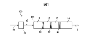
- a first embodiment includes a kneading step of kneading the first component and the second component by an extruder equipped with a kneading zone including a plurality of narrow gap zones in which the gap between the inner wall of the cylinder and the screw is 2 mm or less. I will provide a.
- FIG. 1 is a diagram explaining the steps of the method for producing a resin composition according to the first embodiment.
- the extruder 100 comprises a kneading zone 101 and optionally a melting zone 102 .
- the second component a2 is added to the melt obtained by melting the first component a1 in the melting zone 102 to form a preliminary mixture. and the premix may be fed to the kneading zone 101 .
- the material to be mixed is strongly sheared in the initial melting zone, so that after the first component passes through the melting zone, the second component is applied to the molten first component.
- the component is added from the addition port (side feeder), thermal deterioration of the second component can be suppressed.
- the mixture is kneaded in kneading zone 101 and taken out as resin composition b.
- the kneading zone 101 includes a plurality of narrow gap zones N1, N2, N3 in which the gap between the cylinder inner wall and the screw (also referred to as cylinder gap in the present disclosure) is 2 mm or less.
- the cylinder gap means the gap of the widest channel among the channels through which the material to be mixed can pass from the upstream side to the downstream side of the extruder.
- the gap in the short axis direction of the radial cross section of the screw is defined as the cylinder gap.
- the gap between the screw and the cylinder is the cylinder gap.
- FIG. 1 shows an example in which there are three narrow gap zones, the number of narrow gap zones in the kneading zone may be selected according to the purpose. For example, it may be 10 or less, or 5 or less.
- the cylinder gap [G1] of the narrowest gap zone having the smallest cylinder gap is a narrow gap other than the narrowest gap zone
- the ratio [G1/G2] to the average value [G2] of the cylinder gap of the zone is 0.001 or more, or 0.01 or more, or It is 0.1 or more, and from the viewpoint of suppressing damage to the second component, in one aspect, it is less than 1, or 0.5 or less, or 0.3 or less.
- the average value [G2] means the cylinder clearance value of the zone if there is one zone, and means the arithmetic mean of the cylinder clearance values of the zone if there are two or more.
- the ratio [G1/G3] of [G1] to the cylinder gap [G3] of each of the narrow gap zones other than the narrowest gap zone is, in one aspect, 0.001 or more, or 0.01 or more, or 0.1 or more, and from the viewpoint of suppressing damage to the second component, in one aspect, less than 1, or 0.5 or less, or 0.3 or less be.
- [G1] is preferably 0.001 mm or more, or 0.01 mm or more, or 0.05 mm or more, and preferably 2 mm or less, or 1 mm or less, or 0.5 mm or less.
- [G2] is preferably 0.001 mm or more, or 0.01 mm or more, or 0.05 mm or more, and preferably 2 mm or less, or 1 mm or less, or 0.5 mm or less.
- [G3] is preferably 0.001 mm or more, or 0.01 mm or more, or 0.05 mm or more, and preferably 2 mm or less, or 1 mm or less, or 0.5 mm or less.
- the organic fibers supplied to the extruder have an average fiber length of 1 ⁇ m to 10000 ⁇ m.
- the average fiber length in the present disclosure is a value measured with a scanning electron microscope (SEM) as described below.
- the average fiber length is, in one aspect, 1 ⁇ m or more, or 10 ⁇ m or more, or 50 ⁇ m or more, and in one aspect, 10000 ⁇ m or less, or 1000 ⁇ m or less, or 750 ⁇ m or less, or 600 ⁇ m or less.
- the ratio of [G1] to the average fiber length is preferably 0.001 or more, or 0.01 or more, or 0.1 or more from the viewpoint of suppressing damage to organic fibers, It is preferably 10 or less, 5 or less, or 1 or less from the viewpoint of favorably advancing the miniaturization of organic fibers.
- the organic fibers fed to the extruder form particles with an average particle size of 1 ⁇ m to 10000 ⁇ m.
- the average particle diameter of the particles is 1 ⁇ m or more, or 10 ⁇ m or more, or 50 ⁇ m or more, and in one aspect, it is 10000 ⁇ m or less, or 1000 ⁇ m or less, or 750 ⁇ m or less, or 500 ⁇ m or less.
- the ratio of [G1] to the average particle diameter of the particles is preferably 0.001 or more, or 0.01 or more, or 0.1 or more from the viewpoint of suppressing damage to organic fibers.
- the average particle size in the present disclosure is the d50 particle size measured with a powder tester (for example, powder tester manufactured by Hosokawa Micron Corporation, model number: PT-X).
- the content of the second component in the inflow to each narrow gap zone is determined from the viewpoint of obtaining the desired effect of improving the physical properties of the second component by including the second component in the resin composition at a desired concentration. Therefore, it is preferably 15% by mass or more, or 20% by mass or more, or 30% by mass or more, and from the viewpoint of favorably advancing the refinement of the second component, preferably 90% by mass or less, or 80% by mass % or less, or 70% by mass or less.
- the pressure of the inflow into each narrow gap zone is preferably 0.5 MPa or more, or 1 MPa or more, or 3 MPa or more from the viewpoint of favorably advancing the refinement of the second component. From the viewpoint of suppressing damage, it is preferably 20 MPa or less, 15 MPa or less, or 10 MPa or less. It should be noted that, in one aspect, the pressure of the influent into each narrow gap zone is substantially equal to the pressure of the mixture to be mixed within each narrow gap zone.
- the ratio of the pressure of the effluent from the narrow-gap zone to the pressure of the inflow into the narrow-gap zone is such that increasing the pressure of the influent to the narrow-gap zone causes the refinement of the second component. It is preferably 0.2 or less, or 0.15 or less, or 0.1 or less in terms of being able to proceed well, and suppresses damage to the second component due to sudden pressure changes in the mixture. from the point of view that it is preferably 0.0001 or more, or 0.001 or more, or 0.01 or more. It should be noted that in one aspect, the pressure of the effluent from each narrow gap zone is substantially equal to the mixed pressure in the zone adjacent downstream to each narrow gap zone. It should be noted that the inflow to each zone or the outflow from each zone may be a mixture that enters or exits from each zone. It is not limited to what is provided in advance.
- the pressure of the effluent from the narrow gap zone may in one aspect be 0 MPa or higher, or 0.001 MPa or higher, or 0.01 MPa or higher, and in one aspect 4 MPa or lower, or 2 MPa or lower. , or 1 MPa or less.
- a second embodiment provides a method comprising a kneading step of kneading a first component and a second component with an extruder having a kneading zone including a pressure drop zone.
- the pressure drop zone has an inlet pressure of 0.5 to 20 MPa and a ratio of the pressure of the outlet from the pressure drop zone to the pressure of the inlet to the pressure drop zone of 0. .2 or less.
- the pressure of the inflow into the pressure drop zone is preferably 0.5 MPa or more, or 1 MPa or more, or 3 MPa or more from the viewpoint of favorably advancing the refinement of the second component, and the second component is prevented from being damaged. is preferably 20 MPa or less, or 15 MPa or less, or 10 MPa or less. It should be noted that, in one aspect, the pressure of the inlet to the pressure drop zone is substantially equal to the mixture pressure in the pressure drop zone.
- the content of the second component in the inflow to the pressure drop zone is 15-90% by mass and/or the mixture after passing through the pressure drop zone in the kneading step has more Cold additional polymer is added to cool the mixture.
- the content of the second component in the inflow to the pressure drop zone is 15-90% by weight
- the pressure of the inflow to the pressure drop zone is 0.5-20 MPa
- the ratio of the pressure of the effluent from the pressure drop zone to the pressure of the inflow to the pressure drop zone is less than or equal to 0.2.
- the pressure of the inlet to the pressure drop zone is between 0.5 and 20 MPa and the ratio of the pressure of the outlet from the pressure drop zone to the pressure of the inlet to the pressure drop zone is 0.2 or less. and in the kneading step, the mixture is cooled by adding additional polymer having a lower temperature than the mixture after passing through the pressure drop zone.
- an extruder 200 comprises a kneading zone 201 and optionally a melting zone 202 .
- the second component a2 is added to the melt obtained by melting the first component a1 in the melting zone 202 before the kneading step in the kneading zone 201.
- a further step of obtaining a mixture may be included and a pre-mixture may be supplied to the kneading zone 201 .
- the material to be mixed is strongly sheared in the first melting zone.
- the second When the component is added from the addition port (side feeder), thermal deterioration of the second component can be suppressed.
- the mixture is kneaded in kneading zone 201 and taken out as resin composition b.
- the kneading zone 201 in the second embodiment includes a pressure drop zone D1.
- FIG. 2 shows an example in which there is one pressure drop zone D1, in the second embodiment, the number of pressure drop zones may be selected according to the purpose. 2 or more, or 3 or more, and in one aspect, 10 or less, or 5 or less.
- the pressure drop zone in the second embodiment may, in one aspect, be the narrow gap zone described in the first embodiment.
- the cylinder gap of the narrow gap zone may be the same as exemplified in the first embodiment.
- the pressure drop zone adjusts one or more selected from the group consisting of zone length/cylinder inner diameter ratio, mixture filling rate, temperature, pressure, screw rotation speed, feed amount, resin composition, and space volume fraction of the present disclosure. may be formed by
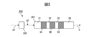
- FIG. 3 is a diagram illustrating steps of a method for producing a resin composition according to the third embodiment.
- the method according to the third embodiment has the following features, it is possible to combine one or more of the features exemplified above for the first or second embodiment except for the features.
- an extruder 300 comprises a kneading zone 301 and optionally a melting zone 302 .
- the melt obtained by melting the first component a1 in the melting zone 202 is fed with the second component a2 by side feeding, for example. to obtain a pre-mixture, and the pre-mixture may be fed to the kneading zone 301 .
- Such an addition mode is preferable from the viewpoint of suppressing thermal deterioration of the second component.
- the mixture is kneaded in kneading zone 301 and taken out as resin composition b.
- the kneading zone 301 includes a plurality of high pressure zones H1, H2, H3 with a pressure of 0.1 MPa or higher.
- FIG. 3 shows an example in which there are three high pressure zones, the number of high pressure zones in the kneading zone may be selected according to the purpose. or less, or 5 or less.
- the pressure [P1] of the highest pressure zone (hereinafter also simply referred to as [P1]) having the highest pressure, the average value of the pressures of the high pressure zones other than the highest pressure zone
- the ratio [P1/P2] to [P2] is greater than 1, or 1.5 or more, or 2 or more, from the viewpoint of favorably advancing the refinement of the second component. From the viewpoint of suppressing the damage of , in one aspect, it is 100 or less, or 50 or less, or 20 or less.
- the average value [P2] means the pressure value of the zone if there is one zone, and means the arithmetic mean of the pressure values of the zone if there are two or more.
- the ratio [P1/P3] of [P1] to the pressure [P3] of each of the high pressure zones other than the highest pressure zone is greater than 1, or It is 1.5 or more, or 2 or more, and from the viewpoint of suppressing damage to the second component, in one aspect, it is 100 or less, or 50 or less, or 20 or less.
- [P1] is 0.5 MPa or more, preferably 1 MPa or more, or 2 MPa or more, and preferably 20 MPa or less, or 15 MPa or less, or 10 MPa or less.
- [P2] is preferably 0.1 MPa or more, or 0.3 MPa or more, or 0.5 MPa or more, and preferably 20 MPa or less, or 15 MPa or less, or 10 MPa or less.
- [P3] is preferably 0.1 MPa or more, or 0.3 MPa or more, or 0.5 MPa or more, and preferably 20 MPa or less, or 15 MPa or less, or 10 MPa or less.
- the zone length/cylinder inner diameter ratio of each of the plurality of high-pressure zones is, in one aspect, 1 or more, 2 or more, or 4 or more, from the viewpoint of favorably advancing the refinement of the second component, and the second In one aspect, it is 30 or less, or 20 or less, or 15 or less, from the viewpoint of suppressing damage to components.
- the pressure of the highest pressure zone is 0.3 MPa or more, or 0.5 MPa or more, or 1 MPa or more from the viewpoint of favorably advancing the refinement of the second component, and damages the second component. From the viewpoint of suppression, in one aspect, it is 50 MPa or less, or 20 MPa or less, or 15 MPa or less.
- the kneading zones 101, 201, 301 may include dispersive mixing zones and distributive mixing zones.
- Narrow gap zones N1, N2, N3, pressure drop zone D1, and high pressure zones H1, H2, H3 are dispersive mixing zones.
- each of the other zones 11, 12, 13, 14, 21, 22, 31, 32, 33, 34 may be dispersive mixing zones or distributive mixing zones.
- the kneading conditions of other zones may be arbitrarily designed to be the same or different from each other as desired.
- the most downstream zone of the kneading zone is a miscellaneous zone (eg, miscellaneous zones 14, 22, 24 in FIGS. 1-3), preferably a distributive mixing zone.
- additional polymer ⁇ 1-3 in the method according to embodiment A, in the kneading zone 101, 201, 301, to the mixture is added an additional polymer of the same type or a different type, preferably the same type as the polymer in the mixture (e.g. side feed).
- the location of addition of additional polymer may be downstream of all narrow gap zones N1, N2, N3 of kneading zone 101 and downstream of pressure drop zone D1 of kneading zone 201. and downstream of all high pressure zones H1, H2, H3 of the kneading zone 301.
- the amount of the additional polymer to be added may be determined according to the kneading conditions, the desired concentration of the second component of the resin composition, and the like. or more, or 30 parts by mass or more, or 50 parts by mass or more, and may be 1000 parts by mass or less, or 500 parts by mass or less, or 400 parts by mass or less, or 300 parts by mass or less.
- the concentration of the second component of the mixture before the addition of the additional polymer is 10 wt% or more, or 15 wt% or more, or 20 wt% or more, or 25 wt% or more, or 30 wt% or more, and / Alternatively, 90% by mass or less, or 80% by mass or less, or 70% by mass or less, or 60% by mass or less, or 50% by mass or less, and the concentration of the second component of the mixture after addition of the additional polymer (one equivalent to the concentration of the second component in the resin composition) is 1% by mass or more, or 2% by mass or more, or 3% by mass or more, or 5% by mass or more, and/or 50% by mass or less. , or 40% by mass or less, or 30% by mass or less, or 20% by mass or less.
- the additional polymer may be cooler than the mixture. That is, in the kneading step, all of the plurality of narrow gap zones according to the first embodiment, or the pressure drop zones according to the second embodiment (if there are multiple, all of them in one aspect), or the third Additional polymer having a lower temperature than the mixture may be added to the mixture after passing through all of the plurality of high pressure zones according to the embodiment of (1) to cool the mixture.
- the temperature of the additional polymer added for cooling is, in one aspect, 0° C. or higher, or 10° C. or higher, or 20° C. or higher, and in one aspect, 300° C. or lower, or 200° C. or lower, or 100° C. or lower. , or 50° C. or less.
- the temperature of the mixture to which the additional polymer is added is, in one aspect, 100° C. or higher, or 150° C. or higher, or 200° C. or higher, and in one aspect, 450° C. or lower, or 400° C. or lower, or 350° C. or lower. .
- the rate of flexural modulus enhancement per unit mass of mixture in each of the high load zones which may be a plurality (i.e., the flexural modulus of the outflow from each zone to the ratio of flexural modulus) is the flexural modulus improvement rate per unit mass of mixture in each zone other than the high-load zone (i.e., the flexural modulus of outflow from each zone to the flexural modulus of inflow into each zone).
- ratio is greater than the maximum value.
- the ratio of the thixotropic index of the outflow from the kneading zone to the thixotropic index of the inflow into the kneading zone is preferably 1 or more from the viewpoint of uniform fine dispersion of the second component by the kneading zone. , or 2 or more, or 3 or more, and preferably 100 or less, or 50 or less, or 10 or less from the viewpoint of suppressing damage to the second component.
- the method according to aspect B of the present disclosure includes a dispersive mixing step of dispersively mixing the first component and the second component in a dispersive mixing zone of the extruder.
- the method according to Aspect B has the following features, but other than this feature, one or more of the features exemplified above with respect to Aspect A can be combined.
- the dispersive mixing zone according to aspect B may comprise a high load zone according to aspect A (more specifically a narrow gap zone, a pressure drop zone or a high pressure zone).
- a method for producing a resin composition containing a first component and a second component comprises a dispersive mixing step of dispersively mixing the first component and the second component in a dispersive mixing zone of an extruder; A first dispersive mixing zone and a second dispersive mixing zone in which at least one of the dispersive mixing zones is selected from the group consisting of zone length/cylinder inner diameter ratio, mixture filling rate, temperature, pressure, and spatial volume fraction is different from each other.
- the second component contains organic fibers, and the mass ratio of components with a diameter of 50 ⁇ m or more in the organic fibers in the inflow to the first dispersive mixing zone is 10% to 90%; A component with a diameter of 50 ⁇ m or more in the organic fiber in the outflow from the first dispersive mixing zone relative to a mass ratio (1a) of a component with a diameter of 50 ⁇ m or more in the organic fiber in the inflow to the first dispersive mixing zone The ratio (1b/1a) of the mass ratio (1b) of is 0 to 0.6, A component with a diameter of 50 ⁇ m or more in the organic fibers in the outflow from the second dispersive mixing zone relative to a mass ratio (2a) of a component with a diameter of 50 ⁇ m or more in the organic fibers in the inflow to the second dispersive mixing zone.
- the [E1] is 1% to 100%, the [E2] is 0% to 10%, the [M1] is 0 GPa to 1 GPa, the [M2] is 0.1 GPa to 20 GPa, and the [E1] Aspects 1 to 4 above, wherein the absolute value of the difference between [E2] is 0.1% to 100%, and the absolute value of the difference between [M1] and [M2] is 0.1 GPa to 20 GPa.
- Method. [6] The method according to any one of aspects 1 to 5, wherein the zone length/cylinder inner diameter ratio of each of the first dispersive-mixing zone and the second dispersive-mixing zone is 1-30.
- a method for producing a resin composition containing a first component and a second component comprises a dispersive mixing step of dispersively mixing the first component and the second component in a dispersive mixing zone of an extruder; In the dispersive mixing zone, by varying one or more selected from the group consisting of zone length/cylinder inner diameter ratio, mixture filling rate, temperature, pressure, and space volume ratio in the cylinder length direction, the mixture advances in the cylinder.
- ⁇ M Flexural modulus change
- the second component contains organic fibers, preferably cellulose fibers, and the organic fibers in the resin composition have an average fiber diameter of 1000 nm or less and an average fiber length/average fiber diameter ratio of 30 or more.
- a method according to any of aspects 1-12. further comprising, prior to the dispersive mixing step, adding the second component to the melt of the first component to obtain a premix, and feeding the premix to the dispersive mixing zone; The method according to any one of aspects 1 to 13 above.
- a region that mainly improves the tensile elongation (also referred to as a tensile elongation improving region in the present disclosure) and a region that mainly improves the tensile elongation
- a region for improving the flexural modulus (also referred to as a flexural modulus improving region in the present disclosure) is provided.
- the coarse agglomerates of the second component can be pulverized, thereby increasing the tensile elongation of the mixture, while pulverizing the coarse agglomerates increases the flexural modulus (i.e., stiffness) of the mixture. contribution to the increase in
- the second component in the flexural modulus enhancing region, can be finely dispersed in the first component, thereby increasing the flexural modulus of the mixture, while fine dispersion increases the tensile elongation of the mixture.
- one of the tensile elongation and the flexural modulus is increased in each of the tensile elongation improving region and the flexural modulus improving region, rather than trying to increase the tensile elongation and the flexural modulus at the same time. Focus on improving. According to the resin composition obtained through such a process, the tensile elongation and flexural modulus are unexpectedly higher than the resin composition obtained through the process of simultaneously increasing the tensile elongation and the flexural modulus. It is possible to achieve both high and stable flexural modulus. The above advantages can be pronounced when the second component comprises organic fibres, especially cellulose fibres. Aspect B more specifically includes the following first and second embodiments.
- FIG. 4 is a diagram for explaining the steps of the method for producing a resin composition according to the first embodiment, and FIG. 5 shows the change behavior of tensile elongation and flexural modulus in the method according to the first embodiment. It is a figure explaining.
- an extruder 400 in a first embodiment, has a dispersive mixing zone 401 .
- Extruder 400 may further have a distributive mixing zone 402 .
- Extruder 400 may also have a melt zone 403 upstream of dispersive mixing zone 401 and/or a melt zone 404 downstream of dispersive mixing zone 401 .
- the method of the present disclosure adds the second component a2 to the melt obtained by melting the first component a1 in the melting zone 403 to form a premix prior to the dispersive mixing step in the dispersive mixing zone 401.
- a premix may be provided to the dispersive mixing zone 401 .
- the second component is added to the molten first component after the resin has passed through the melting zone. When adding from the mouth (side feeder), thermal deterioration of the second component can be suppressed.
- the mixture is dispersively mixed and optionally distributed mixed in an extruder 400 and taken out as a resin composition b.
- the method according to aspect B further comprises adding to the dispersive mixing product after the dispersive mixing step and before the distributive mixing step an additional polymer of the same or different, preferably the same type as the first component in the dispersive mixing product.
- the step of adding to obtain an additional polymer mixture may be further included, and the additional polymer mixture may be fed to the distributive mixing zone.
- additional polymer may be added to the effluent from dispersive mixing zone 401 (eg, by side-feeding additional polymer in melt zone 404 in FIG. 4) before being fed to distributive mixing zone 402 .
- the amount of the additional polymer to be added may be determined according to the kneading conditions, the desired concentration of the second component of the resin composition, etc.
- 10 parts by mass or more with respect to 100 parts by mass of the dispersed mixture product may be 20 parts by weight or more, or 30 parts by weight or more, or 50 parts by weight or more, and may be 1000 parts by weight or less, or 500 parts by weight or less, or 400 parts by weight or less, or 300 parts by weight or less.
- the concentration of the second component of the dispersed mixture product is 10 wt% or more, or 20 wt% or more, or 25 wt% or more, or 30 wt% or more, and/or 80 wt% or less, or 70% by mass or less, or 60% by mass or less, or 50% by mass or less, and the concentration of the second component of the additional polymer mixture (in one aspect, equal to the concentration of the second component in the resin composition) 1% by mass or more, or 2% by mass or more, or 3% by mass or more, or 5% by mass or more, and/or 50% by mass or less, or 40% by mass or less, or 30% by mass or less, or 20% by mass It can be:
- the additional polymer may be cooler than the dispersed mixture product, thereby cooling the dispersed mixture product.
- the temperature of the additional polymer added for cooling is, in one aspect, 0° C. or higher, or 10° C. or higher, or 20° C. or higher, and in one aspect, 300° C. or lower, or 200° C. or lower, or 100° C. or lower. , or 50° C. or less.
- the temperature of the dispersed mixture product to which the additional polymer is added is, in one aspect, 100°C or higher, or 150°C or higher, or 200°C or higher, and in one aspect, 450°C or lower, or 400°C or lower, or 350°C. It is below.
- the dispersive mixing zone 401 comprises a first dispersive mixing zone 41 and a second dispersive mixing zone 42 with different process conditions.
- the first dispersive mixing zone 41 and the second dispersive mixing zone 42 are in direct communication with each other.
- upstream of the first dispersive mixing zone 41, between the first dispersive mixing zone 41 and the second dispersive mixing zone 42, and/or downstream of the second dispersive mixing zone 42, additional dispersive Mixed zones may be present.
- a third dispersive mixing zone (not shown) configured the same as or different from the first dispersive mixing zone 41 or the second dispersive mixing zone 42;
- a configuration can be exemplified in which the effluent from the third dispersive mixing zone is recovered as the resin composition b.
- the process conditions are one or more selected from the group consisting of zone length/cylinder inner diameter ratio, mixture filling rate, temperature, pressure, and spatial volume fraction.
- the above zone length is the total length of the screw elements that make up the dispersive mixing zone and the distributive mixing zone, and depends on the screw configuration.
- the above-mentioned mixture filling rate is the ratio of the actual filling amount (volume basis) of the mixture to the space volume of the extruder, and after suddenly stopping the rotation of the screw and the supply of raw materials, the screw is pulled out and adheres to the screw surface.
- the filled mixture is sampled, weighed, and divided by the density of the mixture to calculate the volume of the filled mixture, followed by dividing the volume of the filled mixture by the spatial volume described below to calculate the mixture fill factor.
- Mixture fill factor is dependent on screw configuration and extrusion conditions.
- the above space volume ratio is calculated by subtracting the screw volume (sum of element volume and shaft volume) from the cylinder volume of the extruder to calculate the space volume, and dividing the space volume by the cylinder volume.
- the spatial volume fraction depends on the screw configuration.
- the increment [M1] of the flexural modulus of the effluent 41b from the first dispersive mixing zone with respect to the flexural modulus of the inflow 41a to the first dispersive mixing zone and the inflow to the second dispersive mixing zone The increment [M2] of the flexural modulus of the effluent 42b from the second dispersive mixing zone with respect to the flexural modulus of 42a satisfies the relationship [M1] ⁇ [M2]. That is, the first dispersive mixing zone is a tensile elongation improving region, and the second dispersive mixing zone is a flexural modulus improving region.
- the first dispersive mixing zone 41 and the second dispersive mixing zone 42 are in communication (in one aspect, the direct communication). Such arrangement is advantageous from the viewpoint of further improving the elastic modulus.
- the first and second dispersive-mixing zones may communicate (in one aspect, direct communication) so that the second dispersive-mixing zone is on the upstream side.
- Such arrangement is advantageous from the viewpoint of further improving elongation.
- the inflow to each zone or the outflow from each zone may be a mixture that enters or exits from each zone. It is not limited to what is provided in advance.
- the mass ratio of the components with a diameter of 50 ⁇ m or more in the organic fibers in the inflow 41a to the first dispersive mixing zone is preferably 10% or more, or It is 20% or more, or 30% or more, or 40% or more, preferably 90% or less, or 80% or less, or 70% or less, or 60% or less. That is, the influent 41a may contain a substantial amount of coarse particles.
- the mass ratio (1a) of the components with a diameter of 50 ⁇ m or more in the organic fibers in the first dispersive mixing zone inflow 41a in the organic fibers in the outflow 41b from the first dispersive mixing zone is preferably 0 or more, or 0.1 or more, or 0.2 or more, and preferably 0.6 or less, or 0 .5 or less, or 0.3 or less.
- coarse particles are pulverized in the first dispersive mixing zone 41, and coarse particles are greatly reduced in the effluent 41b.
- the ratio of the weight ratio (2a) of the 50 ⁇ m or larger diameter component in the organic fibers in the second dispersive mixing zone inflow 42a to the organic fibers in the second dispersive mixing zone effluent 42b is
- the ratio (2b/2a) of the mass ratio (2b) of the component with a diameter of 50 ⁇ m or more is preferably 0.6 or more, or 0.7 or more, or 0.8 or more, and preferably 1 or less, or 0 .9 or less.
- the ratio (2b/2a) is treated as 1 when both the mass ratios (2a) and (2b) are 0%.
- [E1] is preferably 1% or more, or 2% or more, or 3% or more, preferably 100% or less, or 50% or less, or 30% or less
- [E2 ] is preferably 0% or more, preferably 10% or less, or 5% or less, or 3% or less
- [M1] is preferably 0 GPa or more, or 0.1 GPa or more, or 0 .3 GPa or more, preferably 1 GPa or less, or 0.7 GPa or less, or 0.5 GPa or less
- [M2] is preferably 0.1 GPa or more, or 0.5 GPa or more, or 1 GPa or more , preferably 20 GPa or less, or 10 GPa or less, or 5 GPa or less
- the absolute value of the difference between [E1] and [E2] is preferably 0.1% or more, or 1% or more, or 5% or more Yes, preferably 100% or less, or 50% or less, or 30% or less
- the zone length/cylinder inner diameter ratio of each of the first and second dispersive mixing zones is preferably 1 or more, or 3 or more, or 4 or more, and preferably 30 or less, or 20 or less. , or 10 or less.
- the mixture fill factor of each of the first and second dispersive mixing zones is preferably 10% or more, or 50% or more, or 70% or more, preferably 100% or less, or 99%. % or less, or 95% or less.
- the temperature of each of the first and second dispersive mixing zones is preferably 100°C or higher, or 150°C or higher, or 200°C or higher, preferably 400°C or lower, or 350°C or lower. , or 300° C. or less.
- the mixed pressure in each of the first and second dispersive mixing zones is preferably 0 MPa or higher, or 0.1 MPa or higher, or 0.3 MPa or higher, or 1 MPa or higher, preferably 15 MPa. or less, or 10 MPa or less, or 5 MPa or less, or 3 MPa or less.
- the spatial volume fraction of each of the first and second dispersive mixing zones is preferably 10% or more, or 20% or more, or 30% or more, and preferably 70% or less, or 60% or more. % or less, or 50% or less.
- the resin composition dispersed and mixed in the dispersive mixing zone 401 may be introduced into the distributive mixing zone 402 with or without passing through another zone (for example, the melting zone 404) for further distributive mixing.
- Mixing conditions in the distributive mixing zone are not particularly limited, but distributive mixing may be performed by arbitrarily combining kneading disks such as progressive kneading disks and neutral kneading disks.
- FIG. 6 is a diagram for explaining the steps of the method for producing a resin composition according to the second embodiment
- FIG. 7 shows the change behavior of tensile elongation and flexural modulus in the method according to the second embodiment. It is a figure explaining.
- the method according to the second embodiment has the following features, but other than the features, the same procedures and conditions as those described above for the first embodiment may be appropriately employed.
- an extruder 600 has a dispersive mixing zone 601 and may optionally further have a distributive mixing zone 602, a melt zone 603 upstream of the dispersive mixing zone 601, and/or may further include a melt zone 604 downstream of the dispersive mixing zone 601 .
- the second component a2 is added to the melt obtained by melting the first component a1 in the melting zone 603 before the dispersive mixing step in the dispersive mixing zone 601 to form a preliminary mixture. and the premix may be fed to the dispersive mixing zone 601 .
- the mixture is dispersively mixed and optionally distributed mixed in an extruder 600 and taken out as a resin composition b.
- the dispersive mixing zone 601 has a length of in-cylinder travel l of the mixture (i.e., a flow length in the cylinder length direction L as the mixture flows through the dispersive mixing zone 601) due to different process conditions.
- the amount of change in tensile elongation ⁇ E (%) per value (l/d) obtained by dividing the length) (mm) by the cylinder inner diameter d (mm) with respect to the amount of change in flexural modulus ⁇ M (GPa) per l/d
- the ratio [ ⁇ E/ ⁇ M] is varied in the longitudinal direction L of the cylinder.
- the process conditions are one or more selected from the group consisting of zone length/cylinder inner diameter ratio, mixture fill factor, temperature, pressure, and void volume fraction.
- the ratio [ ⁇ E/ ⁇ M] is gradually decreased from upstream to downstream of the cylinder.
- the more upstream side of the cylinder corresponds to the tensile elongation improvement region, and the more downstream side corresponds to the flexural modulus improvement region, which is advantageous in that a resin composition with higher rigidity can be obtained.
- ⁇ E may gradually decrease and ⁇ M may gradually increase from the upstream side to the downstream side of the cylinder.
- ⁇ E is 0.1% or more, or 1% or more, or 10% or more, and 300% or less, or 200% or less, or 100% or less.
- range may be tapered to a range of 0.01% or more, or 0.1% or more, or 0.5% or more, and 10% or less, or 5% or less, or 2% or less, wherein ⁇ M is 0.001 GPa or more, or 0.01 GPa or more, or 0.05 GPa or more, and 10 GPa or less, or 5 GPa or less, or 2 GPa or less, to 0.02 GPa or more, or 0.05 GPa or more, or 0.1 GPa or more and may be gradually increased to a range that is 50 GPa or less, or 10 GPa or less, or 5 GPa or less.
- the ratio [ ⁇ E/ ⁇ M] is gradually increased from upstream to downstream of the cylinder.
- the more upstream side of the cylinder corresponds to the flexural modulus improving region, and the more downstream side corresponds to the tensile elongation improving region, which is advantageous in that a resin composition with higher elongation can be obtained.
- ⁇ E may gradually increase and ⁇ M may gradually decrease from upstream to downstream of the cylinder.
- ⁇ E is 0.01% or more, or 0.1% or more, or 0.5% or more, and 10% or less, or 5% or less, or 2% or less, may be gradually increased to a range of 0.1% or more, or 1% or more, or 10% or more, and 300% or less, or 200% or less, or 100% or less, and ⁇ M is 0 .02 GPa or more, or 0.05 GPa or more, or 0.1 GPa or more, 50 GPa or less, or 10 GPa or less, or 5 GPa or less, to 0.001 GPa or more, or 0.01 GPa or more, or 0.05 GPa or more Yes, and may be gradually decreased to a range of 10 GPa or less, or 5 GPa or less, or 2 GPa or less.
- a method according to aspect C of the present disclosure comprises a dispersive mixing step of dispersively mixing a first component and a second component in a dispersive mixing zone of an extruder to obtain a dispersive mixing product; and a distributive mixing step of distributively mixing at least the dispersive mixing product to obtain a resin composition.
- the method according to Aspect C has the following features, but one or more of the features exemplified above with respect to Aspect A can be combined in addition to these features.
- the dispersive mixing zone according to aspect C may comprise a high load zone according to aspect A (more specifically a narrow gap zone, a pressure drop zone or a high pressure zone).
- a method for producing a resin composition containing a first component and a second component comprising: a dispersive mixing step of dispersively mixing the first component and the second component in a dispersive mixing zone of the extruder to obtain a dispersive mixing product; a distributive mixing step of distributively mixing at least the dispersive mixing product in a distributive mixing zone of an extruder to obtain a resin composition; including The dispersive mixing zone and the distributive mixing zone differ from each other in one or more selected from the group consisting of zone length/cylinder inner diameter ratio, mixture filling rate, temperature, pressure, and spatial volume fraction; Incremental tensile elongation [EA] of effluent from said dispersive mixing zone relative to tensile elongation of influent to said distributive mixing zone and from said distributive mixing zone relative to tensile elongation of influent to said distributive mixing zone The increment of tensile elongation [EB] of the effluent satisfies the relationship
- the [EA] is 1% to 100%, the [EB] is 0% to 10%, the [MA] is 0.1 GPa to 20 GPa, the [MB] is 0 GPa to 1 GPa, [EA] and [ EB] and the difference ([EA] - [EB]) is 0.01% to 100%, and the difference between [MA] and [MB] ([MA] - [MB]) is 0.001GPa to 10GPa.
- a method for producing a resin composition containing a first component and a second component comprising: a dispersive mixing step of dispersively mixing the cellulose fibers and the resin in the dispersive mixing zone of the extruder to obtain a dispersed mixed product; a distributive mixing step of distributively mixing at least the dispersive mixing product in a distributive mixing zone of an extruder to obtain a resin composition; including
- the concentration [CA] of the second component in the dispersive mixing zone is from 10% to 90% by weight
- the concentration [CB] of the second component in the distributive mixing zone is from 1% to 50% by weight
- the ratio [ CA]/[CB] is 2-90.
- FIG. 8 is a diagram explaining steps of a method for producing a resin composition according to one embodiment of the present invention.
- extruder 800 has dispersive mixing zone 801 and distributive mixing zone 802 .
- a distributive mixing zone 802 is positioned downstream of the dispersive mixing zone 801, as shown in FIG.
- the extruder 800 may also have a melt zone 803 upstream from the dispersive mixing zone 801 and/or a melt zone 804 downstream from the dispersive mixing zone 801 and upstream from the distributive mixing zone 802. .
- the second component a2 is added to the melt obtained by melting the first component a1 in the melting zone 803 before the dispersive mixing step in the dispersive mixing zone 801 to obtain a preliminary mixture.
- a further step may be included wherein the premix may be fed to the dispersive mixing zone 801 .
- the material to be mixed is strongly sheared in the initial melting zone, so that after the first component passes through the melting zone, the second component is applied to the molten first component.
- the component is added from the addition port (side feeder), thermal deterioration of the second component can be suppressed.
- the mixture is dispersively mixed and distributed mixed in an extruder 800 and taken out as a resin composition b.
- the method according to aspect C further comprises adding to the dispersive mixing product after the dispersive mixing step and before the distributive mixing step an additional polymer of the same or different, preferably the same type as the first component in the dispersive mixing product.
- the step of adding to obtain an additional polymer mixture may be further included, and the additional polymer mixture may be fed to the distributive mixing zone.
- additional polymer may be added to the effluent from dispersive mixing zone 801 (eg, by side-feeding additional polymer in melt zone 804 in FIG. 8) before being fed to distributive mixing zone 802 .
- the amount of the additional polymer to be added may be determined according to the kneading conditions, the desired concentration of the second component of the resin composition, etc.
- 10 parts by mass or more with respect to 100 parts by mass of the dispersed mixture product may be 20 parts by weight or more, or 30 parts by weight or more, or 50 parts by weight or more, and may be 1000 parts by weight or less, or 500 parts by weight or less, or 400 parts by weight or less, or 300 parts by weight or less.
- the concentration of the second component of the dispersed mixture product is 10 wt% or more, or 20 wt% or more, or 25 wt% or more, or 30 wt% or more, and/or 80 wt% or less, or 70% by mass or less, or 60% by mass or less, or 50% by mass or less, and the concentration of the second component of the additional polymer mixture (in one aspect, equal to the concentration of the second component in the resin composition) 1% by mass or more, or 2% by mass or more, or 3% by mass or more, or 5% by mass or more, and/or 50% by mass or less, or 40% by mass or less, or 30% by mass or less, or 20% by mass It can be:
- the additional polymer may be cooler than the dispersed mixture product, thereby cooling the dispersed mixture product.
- the temperature of the additional polymer added for cooling is, in one aspect, 0° C. or higher, or 10° C. or higher, or 20° C. or higher, and in one aspect, 300° C. or lower, or 200° C. or lower, or 100° C. or lower. , or 50° C. or less.
- the temperature of the dispersed mixture product to which the additional polymer is added is, in one aspect, 100°C or higher, or 150°C or higher, or 200°C or higher, and in one aspect, 450°C or lower, or 400°C or lower, or 350°C. It is below. Aspect C more specifically includes the following first and second embodiments.
- the dispersive mixing zone 801 and the distributive mixing zone 802 differ from each other in process conditions.
- the process conditions are one or more selected from the group consisting of zone length/cylinder inner diameter ratio, mixture fill factor, temperature, pressure, and void volume fraction.
- the above zone length is the total length of the screw elements that make up the dispersive mixing zone and the distributive mixing zone, and depends on the screw configuration.
- the above-mentioned mixture filling rate is the ratio of the actual filling amount (volume basis) of the mixture to the space volume of the extruder, and after suddenly stopping the rotation of the screw and the supply of raw materials, the screw is pulled out and adheres to the screw surface.
- the filled mixture is sampled, weighed, and divided by the density of the mixture to calculate the volume of the filled mixture, followed by dividing the volume of the filled mixture by the spatial volume described below to calculate the mixture fill factor.
- Mixture fill factor is dependent on screw configuration and extrusion conditions.
- the space volume ratio is calculated by subtracting the screw volume (the sum of the element volume and the shaft volume) from the barrel volume of the extruder to calculate the space volume, and then dividing the space volume by the barrel volume.
- the spatial volume fraction depends on the screw configuration.
- the incremental tensile elongation [EA] of the effluent from the dispersive mixing zone 801 relative to the tensile elongation of the influent to the dispersive mixing zone 801 and the tensile elongation of the influent to the distributive mixing zone 802 are
- the incremental tensile elongation [EB] of the outflow from the distributive mixing zone 802 satisfies the relationship [EA]>[EB] and the flexural modulus of the inflow of the dispersive mixing zone 801 from the dispersive mixing zone 801 to the flexural modulus of the inflow of 801 into the dispersive mixing zone and the flexural modulus increment of the outflow from the distributive-mixing zone 802 with respect to the flexural modulus of the inflow into the distributive-mixing zone 802 [MB] is given by [MA] > satisfies the relationship of [MB].
- the inflow to each zone or the outflow from each zone may be a mixture that enters or exits from each zone. It is not limited to what is provided in advance.
- [EA] is preferably 1% or more, or 2% or more, or 3% or more, and preferably 100% or less, or 50% or less, or 30% or less.
- [EB] is preferably 0% or more, or 0.1% or more, or 0.5% or more, and preferably 10% or less, or 5% or less, or 3% or less.
- [MA] is preferably 0.1 GPa or more, or 0.5 GPa or more, or 1 GPa or more, and preferably 20 GPa or less, or 10 GPa or less, or 5 GPa or less.
- [MB] is preferably 0 GPa or more, or 0.1 GPa or more, or 0.3 GPa or more, and preferably 1 GPa or less, or 0.7 GPa or less, or 0.5 GPa or less.
- the difference between [EA] and [EB] is preferably 0.01% or more, or 0.1% or more, or 1% or more, and preferably 100% or less , or 50% or less, or 10% or less.
- the difference between [MA] and [MB] ([MA]-[MB]) is preferably 0.001 GPa or more, or 0.01 GPa or more, or 0.1 GPa or more, preferably 10 GPa or less, or It is 5 GPa or less, or 1 GPa or less.
- the zone length/cylinder inner diameter ratio of each of the dispersive mixing zone 801 and the distributive mixing zone 802 is preferably 1 or more, or 3 or more, or 4 or more, and preferably 30 or less, or 20 or less. , or 10 or less.
- the mixture fill factor of each of the dispersive mixing zone 801 and the distributive mixing zone 802 is preferably 10% or more, or 50% or more, or 70% or more, and preferably 100% or less, or 99% or more. % or less, or 95% or less.
- the temperature of each of the dispersive mixing zone 801 and the distributive mixing zone 802 is preferably 100°C or higher, or 150°C or higher, or 200°C or higher, and preferably 400°C or lower, or 350°C or lower. , or 300° C. or less.
- the mixed pressure in each of the dispersive mixing zone 801 and the distributive mixing zone 802 is preferably 0 MPa or higher, or 0.1 MPa or higher, or 0.3 MPa or higher, or 1 MPa or higher, preferably 15 MPa. or less, or 10 MPa or less, or 5 MPa or less, or 3 MPa or less.
- the spatial volume fraction of each of the dispersive mixing zone 801 and the distributive mixing zone 802 is preferably 10% or more, or 20% or more, or 30% or more, and preferably 70% or less, or 60% or more. % or less, or 50% or less.
- the zone length/cylinder inner diameter ratio of the dispersive mixing zone 801 is 1 or more, or 2 or more, or 5 or more
- the zone length/cylinder inner diameter ratio of the distributive mixing zone 802 is 5 or less, or 2 or less, or 1 or less.
- the mixture pressure is 0.1 MPa or more, or 0.2 MPa or more, or 0.3 MPa or more, or 0.5 MPa or more, or 1 MPa or more, or 3 MPa or more, or 5 MPa or more, or 7 MPa or more. From the viewpoint of suppressing damage to the second component, the mixture pressure may preferably be 20 MPa or less, 15 MPa or less, or 10 MPa or less.
- the area in which high pressure is applied to the material to be mixed can be relatively wide in the dispersive mixing zone 801 and relatively narrow in the distributive mixing zone 802 .
- the region where the mixture pressure is within the above range may be a region where the zone length/cylinder inner diameter ratio of the dispersive mixing zone 801 is 30 or less, 20 or less, or 10 or less.
- the pressure of the mixture to be mixed is 0.3 MPa or more in the region where the zone length/cylinder inner diameter ratio of the dispersive mixing zone is 1 or more and the zone length/cylinder inner diameter ratio of the distributive mixing zone is 5 or less.
- the physical property improvement rate per unit mass of the second component in the mixture is higher in the distributive mixing zone than in the dispersive mixing zone. and big.
- the physical property improvement rate of the dispersive mixing zone is the ratio of the physical properties of the outflow from the dispersive mixing zone to the physical properties of the inflow to the dispersive mixing zone. It is the ratio of the physical properties of the effluent from the distributive mixing zone to the physical properties.
- the physical property is selected from tensile elongation and flexural modulus.
- the ratio of the physical property improvement ratio of the distributive mixing zone to the dispersive mixing zone is preferably more than 1, or 1.2 or more, or 1.5 or more from the above viewpoint, and from the viewpoint of ease of designing process conditions , for example, 100 or less, or 10 or less, or 5 or less.
- the concentration [CA] of the second component in dispersive mixing zone 801 is between 10% and 90% by weight, and the concentration of the second component in distributive mixing zone 802 is The concentration [CB] is 1 mass % to 50 mass %, and the ratio [CA]/[CB] is 2 to 90.
- adding additional polymer to the effluent from dispersive mixing zone 801 e.g., by side-feeding the additional polymer in melt zone 804 of FIG. 8
- adding additional polymer to the effluent from dispersive mixing zone 801 e.g., by side-feeding the additional polymer in melt zone 804 of FIG. 8
- the second component is The concentration can be adjusted within the above range.
- the second component is finely divided in the dispersive mixing zone 801 and the second component in the distributive mixing zone 802. It is possible to improve the second component dispersion state while avoiding damage to the components.
- the concentration [CA] is 10% by mass or more, or 15% by mass or more, or 20% by mass or more from the viewpoint of favorably advancing the refinement of the second component, and damages the second component. from the viewpoint of suppressing, in one aspect, it is 90% by mass or less, or 80% by mass or less, or 70% by mass or less.
- the concentration [CB] is, in one aspect, 1% by mass or more, or 5% by mass or more, or 10% by mass or more. , from the viewpoint of suppressing damage to the second component, in one aspect, it is 50% by mass or less, or 40% by mass or less, or 30% by mass or less.
- the ratio [CA]/[CB] is 2 or more, or 3 or more, or 4 or more from the viewpoint of promoting miniaturization in the dispersive mixing step of the second component and suppressing damage in the distributive mixing step. From the viewpoint of avoiding damage to the second component due to too large a concentration [CA] or limiting the application of the resin composition due to too small a concentration [CB], in one aspect, 90 or less, or 50 or less, or 10 or less.
- the increment [TA] of the thixotropic index of the output from the dispersive mixing zone 801 relative to the thixotropic index of the input to the distributive mixing zone 801 and the distributive mixing zone relative to the thixotropic index of the input to the distributive mixing zone 802 The thixotropic index increment [TB] of the outflow from 802 satisfies the relationship [TA]>[TB].
- [TA]>[TB] is an indicator of preferential refinement of the second component in the dispersive mixing zone 801 over the distributive mixing zone 802 .
- the [TA]/[TB] ratio is preferably greater than 1, or 2 or more, or 3 or more from the viewpoint of preferentially miniaturizing the second component in the dispersive mixing zone 801. It is preferably 100 or less, 50 or less, or 10 or less from the viewpoint of suppressing damage to the second component due to excessive refinement of the second component in .
- a method for measuring the thixotropic index will be described later.
- the increment [TA] is preferably greater than 0.01 and 10 or less, or 0.05-5, or 0.1-2.
- the increment [TB] is preferably from 0.01 to less than 10, or from 0.05 to 5, or from 0.1 to 2.
- the resin composition exiting the kneading zone 101, 201, 301 (for aspect A), the distributive mixing zone 402, 602 (for aspect B), or the distributive mixing zone 802 (for aspect C) b may be extruded out of the extruder in the desired shape.
- pellet form is preferred for ease of post-processing and transportation.
- shape of pellets include round, elliptical, and cylindrical shapes, which vary depending on the cutting method during extrusion.
- the size of round pellets can be exemplified by a diameter of 1 mm or more and 3 mm or less
- the size of cylindrical pellets can be exemplified by a diameter of 1 mm or more and 3 mm or less and a length of 2 mm or more and 10 mm or less.
- the above diameter and length are desirably at least the lower limit, and from the viewpoint of biting into a molding machine in post-processing, they are preferably at most the upper limit.
- the resin composition produced by the methods according to aspects A to C may be molded into various forms such as films, sheets, fibers, plates, powders, and three-dimensional structures.
- molding methods include injection molding, extrusion molding, foam molding, insert molding, in-mold coating molding, and mold molding.
- various extrusion molding methods are suitable for molding sheets, films, fibers, and the like.
- the molding temperature can be appropriately selected depending on the composition of the resin composition and the like. Alternatively, the melting point may be +80° C. or lower, or the melting point +70° C. or lower.
- the resin composition produced by the method according to the present disclosure comprises a first component that is a polymer and organic fibers and/or a second component that is a polymer different from the first component.
- a polymer different from the first component means, in one aspect, a polymer different in molecular structure and/or molecular weight from the first component.
- the polymer in the first component, the organic fiber in the second component, and the polymer in the second component may each be one kind or two or more kinds.
- the polymer in the first component and the polymer in the second component differ from each other in molecular structure and/or molecular weight of at least one polymer constituting them.
- the second component is in one aspect an organic fiber, in one aspect a polymer, and in one aspect a combination of an organic fiber and a polymer. Examples of material components used for producing the resin composition and therefore contained in the resin composition include the following.
- the first component is, in one aspect, a polymer.
- the polymer is appropriately selected according to the purpose of use of the resin composition.
- a crystalline thermoplastic resin having a melting point within the range of 100°C to 350°C, or a glass transition point within the range of 100°C to 250°C. It may be an amorphous thermoplastic resin or the like.
- the polymer include polyolefin-based resins, polyamide-based resins, polyester-based resins, polyacetal-based resins, polyphenylene ether-based resins, polyphenylene sulfide-based resins, and mixtures of two or more of these.
- the melting point of the thermoplastic resin is preferably 140°C or higher, or 150°C or higher, or 160°C or higher, or 170°C or higher, or 180°C or higher. , or 190° C. or higher, or 200° C. or higher, or 210° C. or higher, 220° C. or higher, or 230° C. or higher, or 240° C. or higher, or 245° C. or higher, or 250° C. or higher.
- the melting point of the thermoplastic resin is, for example, 150° C. to 190° C. or 160° C. to 180° C. for relatively low melting point resins (eg, polyolefin resins), and relatively high melting point resins (eg, polyamide resins). 220° C. to 350° C. or 230° C. to 320° C. can be exemplified.
- the melting point refers to the peak top temperature of the endothermic peak that appears when the temperature is raised from 23 ° C. at a rate of 10 ° C./min using a differential scanning calorimeter (DSC). When two or more appear, it refers to the peak top temperature of the endothermic peak on the highest temperature side. Further, in the present disclosure, the glass transition point is the temperature obtained using the dynamic viscoelasticity measuring device as described above.
- a polyolefin-based resin that is preferable as a polymer is a polymer obtained by polymerizing olefins (eg, ⁇ -olefins) or alkenes as monomer units.
- polyolefin-based resins include ethylene-based (co)polymers such as low-density polyethylene (e.g., linear low-density polyethylene), high-density polyethylene, ultra-low-density polyethylene, and ultra-high-molecular-weight polyethylene, polypropylene, and ethylene.
- polypropylene (co)polymers exemplified by propylene copolymers, ethylene-propylene-diene copolymers, ethylene-acrylic acid copolymers, ethylene-methyl methacrylate copolymers, ethylene-glycidyl methacrylate copolymers
- examples thereof include copolymers of ⁇ -olefins such as ethylene represented by coalescence.
- Polypropylene is the most preferred polyolefin resin here.
- polypropylene having a melt mass flow rate (MFR) of 3 g/10 min or more and 30 g/10 min or less measured at 230° C. under a load of 21.2 N in accordance with ISO 1133 is preferred.
- MFR melt mass flow rate
- the lower limit of MFR is more preferably 5 g/10 minutes, still more preferably 6 g/10 minutes, and most preferably 8 g/10 minutes.
- the upper limit is more preferably 25 g/10 minutes, still more preferably 20 g/10 minutes, and most preferably 18 g/10 minutes.
- the MFR desirably does not exceed the above upper limit from the viewpoint of improving the toughness of the composition, and preferably does not fall below the above lower limit from the viewpoint of the fluidity of the composition.
- acid-modified polyolefin resins can also be suitably used in order to increase affinity with cellulose.
- the acid in this case can be appropriately selected from maleic acid, fumaric acid, succinic acid, phthalic acid, their anhydrides, and polycarboxylic acids such as citric acid. Among these, maleic acid or its anhydride is preferable because the modification rate can be easily increased.
- the modification method is not particularly limited, but a method of heating above the melting point in the presence or absence of a peroxide to melt and knead is common.
- the polyolefin resin to be acid-modified all of the polyolefin resins described above can be used, but polypropylene is particularly suitable for use.
- the acid-modified polypropylene may be used alone, it is more preferable to use it in combination with unmodified polypropylene in order to adjust the modification rate of the resin as a whole.
- the ratio of acid-modified polypropylene to all polypropylene at this time is 0.5% by mass to 50% by mass.
- a more preferable lower limit is 1% by mass, still more preferably 2% by mass, still more preferably 3% by mass, particularly preferably 4% by mass, and most preferably 5% by mass.
- a more preferred upper limit is 45% by mass, still more preferably 40% by mass, still more preferably 35% by mass, particularly preferably 30% by mass, and most preferably 20% by mass.
- the lower limit or more is preferable, and in order to maintain the ductility of the resin, the upper limit The following are preferred.
- the melt mass flow rate (MFR) of acid-modified polypropylene is measured at the interface between the first component and the second component (e.g. the interface between cellulose and resin ), it is preferably 50 g/10 minutes or more.
- a more preferred lower limit is 100 g/10 min, even more preferably 150 g/10 min, and most preferably 200 g/10 min. Although there is no particular upper limit, it is 500 g/10 minutes for maintenance of mechanical strength.
- Polyamide resins include polyamide 6, polyamide 11, polyamide 12 obtained by polycondensation reaction of lactams, 1,6-hexanediamine, 2-methyl-1,5-pentanediamine, 1,7-heptanediamine, 2-methyl-1-6-hexanediamine, 1,8-octanediamine, 2-methyl-1,7-heptanediamine, 1,9-nonanediamine, 2-methyl-1,8-octanediamine, 1,10- Diamines such as decanediamine, 1,11-undecanediamine, 1,12-dodecanediamine, m-xylylenediamine, butanedioic acid, pentanedioic acid, hexanedioic acid, heptanedioic acid, octanedioic acid, nonanedioic acid acid, decanedioic acid, benzene-1,2-dicarboxylic acid, benzene-1,3-dicarboxy
- aliphatic polyamides such as polyamide 6, polyamide 11, polyamide 12, polyamide 6,6, polyamide 6,10, polyamide 6,11, polyamide 6,12, polyamide 6,C, polyamide 2M5,C Alicyclic polyamides such as
- the terminal carboxyl group concentration of the polyamide resin is not particularly limited, but is preferably 20 ⁇ mol/g or more, or 25 ⁇ mol/g or more, preferably 150 ⁇ mol/g or less, or 100 ⁇ mol/g. may be:
- the terminal amino group concentration of the polyamide resin is preferably 20 ⁇ mol/g or more, or 30 ⁇ mol/g or more, and preferably 150 ⁇ mol/g or less, or 100 ⁇ mol/g or less.
- the total concentration of the terminal amino group and the terminal carboxyl group of the polyamide resin is not particularly limited, but is preferably 10 ⁇ mol/g or more, or 50 ⁇ mol/g or more, or 100 ⁇ mol/g or more, or 135 ⁇ mol/g. or more, and from the viewpoint of preventing a decrease in viscosity due to an excessively low molecular weight of the resin and suppressing burr generation during molding, it is preferably 500 ⁇ mol/g or less, or 300 ⁇ mol/g or less, or 135 ⁇ mol/g or less, or 100 ⁇ mol/g or less.
- the ratio of amino terminal groups to carboxyl terminal groups ([NH 2 ]/[COOH]) of the polyamide resin is preferably greater than 1.00, or 1.01 or more, or 1.05 or more, or 1.10 or more. is.
- the upper limit of the amino terminal group ratio is not particularly limited, but it may be preferably 10000 or less, or 1000 or less, or 100 or less, or 10 or less from the viewpoint of maintaining good color tone of the resin composition.
- a known method can be used as a method for adjusting the terminal group concentration of the polyamide resin.
- a diamine compound, a monoamine compound, a dicarboxylic acid compound, a monocarboxylic acid compound, an acid anhydride, a monoisocyanate, a monoacid halide, a monoester, a monoalcohol, etc. can be used to obtain a predetermined terminal group concentration during polymerization of the polyamide.
- a method of adding a terminal adjuster that reacts with the terminal group to the polymerization liquid can be used.
- the amino terminal group and carboxyl terminal group concentrations of the polyamide-based resin can be determined from the integrated value of characteristic signals corresponding to each terminal group by 1 H-NMR. Specifically, the method described in JP-A-7-228775 is recommended.
- the polyamide resin preferably has an intrinsic viscosity [ ⁇ ] of 0.6 to 2.0 dL/g, and preferably 0.7 to 1.4 dL/g, measured at 30°C in concentrated sulfuric acid. is more preferred, 0.7 to 1.2 dL/g is even more preferred, and 0.7 to 1.0 dL/g is particularly preferred.
- the use of a polyamide having an intrinsic viscosity within the above range has the advantage of increasing the fluidity of the resin composition in the mold during injection molding and improving the appearance of the molded piece.
- intrinsic viscosity is synonymous with viscosity generally called intrinsic viscosity, and is described, for example, in Polymer Process Engineering (Prentice-Hall, Inc. 1994), pages 291-294. can be measured by
- Polyester-based resins include polyethylene terephthalate (PET), polybutylene terephthalate (PBT), polyethylene naphthalate (PEN), polybutylene succinate (PBS), polybutylene succinate adipate (PBSA), and polybutylene adipate terephthalate (PBAT). , polyhydroxyalkanoic acid (PHA), polylactic acid (PLA), polyarylate (PAR), polycarbonate (PC), and the like. PET, PBS, PBSA, PBT, and PEN are more preferred as the polyester-based resin, and PBS, PBSA, and PBT are even more preferred.
- the terminal groups of the polyester resin can be freely changed depending on the monomer ratio during polymerization and the presence or absence and amount of addition of a terminal stabilizer. More preferably, the ratio ([COOH]/[total terminal groups]) is from 0.30 to 0.95.
- the carboxyl end group ratio lower limit is more preferably 0.35, still more preferably 0.40, and most preferably 0.45.
- the upper limit of the carboxyl terminal group ratio is more preferably 0.90, still more preferably 0.85, and most preferably 0.80.
- the carboxyl terminal group ratio is desirably 0.30 or more from the viewpoint of dispersibility of cellulose in the composition, and desirably 0.95 or less from the viewpoint of the color tone of the resulting composition.
- polyacetal resins homopolyacetal made from formaldehyde and copolyacetal containing trioxane as a main monomer and 1,3-dioxolane as a comonomer component are generally used. From the viewpoint of thermal stability, copolyacetal can be preferably used.
- the amount of comonomer component (eg, 1,3-dioxolane)-derived structure is more preferably in the range of 0.01 to 4 mol %.
- a preferred lower limit for the amount of comonomer component-derived structures is 0.05 mol %, more preferably 0.1 mol %, and even more preferably 0.2 mol %.
- a preferred upper limit is 3.5 mol %, more preferably 3.0 mol %, even more preferably 2.5 mol %, most preferably 2.3 mol %.
- the lower limit be within the above range
- the upper limit be within the above range
- a polymer having a hydrophilic group (eg, one or more selected from a hydroxyl group, an amino group, and a carboxy group) is particularly preferable, for example, from the viewpoint of affinity with cellulose.
- Preferred examples of polymers having hydrophilic groups are selected from the group consisting of acid-modified polyolefin resins, polyacetal resins, polycarbonate resins, polyamide resins, polyester resins, polyphenylene ether resins, and acrylic resins. More than seeds. Among them, polyamide-based resins and maleated polypropylene are preferred.
- the second component is organic fibers and/or polymers.
- the second component is dispersed in the first component by being mixed with the first component, and the physical properties of the resin composition (in one aspect, tensile elongation, flexural modulus, coefficient of thermal expansion , and physical stability, preferably all of these) can be improved over the absence of the second component.
- the amount of the second component relative to 100% by mass of the entire resin composition, or the amount of the second component relative to the total 100% by mass of the first component and the second component is preferably , 0.1% by mass or more, or 0.5% by mass or more, or 1% by mass or more, or 3% by mass or more, preferably 30% by mass or less, or 25% by mass or less, or 20% by mass or less, Or it is 15% by mass or less.
- the amount of the second component is within the above range, it is preferable from the viewpoint of high tensile elongation, high flexural modulus, low coefficient of thermal expansion, and/or good physical property stability. Preferred examples of each of the organic fibers and polymers are described below.
- Organic fibers are fibers composed of organic materials.
- Organic fibers are polymer fibers in one aspect, fibers having hydrogen bond forming structures (e.g. OH structures and/or NH structures) in one aspect, and natural fibers (e.g. cellulose fibers, cellulose fibers) in one aspect. nanocrystal, chitin fiber, chitosan fiber, wool, etc.), and synthetic fiber (e.g., aramid fiber, nylon fiber, acrylic fiber, polyester fiber, vinylon fiber, rayon fiber, polyurethane fiber, etc.). That's it.
- cellulose fiber means cellulose with an L/D of 30 or more
- cellulose nanocrystal means cellulose with an average fiber diameter of 1000 nm or less and an L/D of less than 30.
- the amount of organic fibers relative to 100% by mass of the entire resin composition is preferably 0.1% by mass or more, or 0.5% by mass or more, or 1% by mass or more, or 3% by mass or more. , preferably 30% by mass or less, or 25% by mass or less, or 20% by mass or less, or 15% by mass or less.
- An amount of organic fiber within the above range is preferable from the viewpoint of high tensile elongation, high flexural modulus, low coefficient of thermal expansion, and/or good physical property stability.
- the organic fibers comprise or are cellulose fibers.
- Sources of cellulose fibers include natural cellulose fibers and regenerated cellulose fibers.
- Natural cellulose fibers include wood pulp obtained from wood species (hardwood or softwood), non-wood pulp obtained from non-wood species (bamboo, hemp fiber, bagasse, kenaf, linter, etc.), and refined pulps of these (purified linter, etc.) can be used.
- non-wood pulp cotton-derived pulp including cotton linter pulp, hemp-derived pulp, bagasse-derived pulp, kenaf-derived pulp, bamboo-derived pulp, straw-derived pulp, and the like can be used.
- Cotton-derived pulp, hemp-derived pulp, bagasse-derived pulp, kenaf-derived pulp, bamboo-derived pulp, and straw-derived pulp are cotton lints, cotton linters, hemp-based abaca (e.g., from Ecuador or the Philippines), and zeisal, respectively. , bagasse, kenaf, bamboo, straw, etc., through a refining process such as delignification by digestion, a bleaching process, etc., and a refined pulp as a raw material.
- the cellulose fibers are cellulose nanofibers.
- Cellulose nanofibers are produced, for example, by treating the above-mentioned pulp with hot water at 100° C. or higher, hydrolyzing the hemicellulose portion to make it brittle, and then pulverizing with a high-pressure homogenizer, microfluidizer, ball mill, disc mill, or the like. It can be obtained by fibrillation.
- the number average fiber diameter of the cellulose nanofibers is 2 to 1000 nm, preferably 4 nm or more, or 5 nm or more, or 10 nm or more, or 15 nm or more, or 20 nm or more, or 50 nm or more, or 100 nm or more. , preferably 500 nm or less, or 450 nm or less, or 400 nm or less, or 350 nm or less, or 300 nm or less, or 250 nm or less, or 200 nm or less.
- the number average fiber length/number average fiber diameter ratio (L/D) of cellulose nanofibers may be 30 or more, or 50 or more, or 80 or more, or 100 or more in one embodiment, and in one embodiment, 5000 or less. , or 4000 or less, or 3000 or less.
- the number average fiber diameter (D), number average fiber length (L), and L/D ratio of the cellulose fibers of the present disclosure are measured using a scanning electron microscope (SEM) according to the following procedure. value.
- SEM scanning electron microscope
- An aqueous dispersion of cellulose fibers is substituted with tert-butanol, diluted to 0.001 to 0.1% by mass, and treated with a high-shear homogenizer (for example, IKA, product name "Ultra Turrax T18”) under processing conditions: Dispersed at a rotation speed of 15,000 rpm for 3 minutes, cast on an osmium-evaporated silicon substrate, air-dried, and used as a measurement sample.
- a high-shear homogenizer for example, IKA, product name "Ultra Turrax T18
- the length (L) and diameter (D) of 100 randomly selected fibrous substances in an observation field whose magnification is adjusted so that at least 100 fibrous substances can be observed. is measured and the ratio (L/D) is calculated. Calculate the number average length (L), number average diameter (D), and number average ratio (L/D) for the cellulose fibers.
- the length, diameter, and L/D ratio of the cellulose fibers in the resin composition and the molded product are determined by dissolving the polymer component in an organic or inorganic solvent capable of dissolving the polymer component, separating the cellulose fibers, and adjusting the After thorough washing with a solvent, substitution with tert-butanol to prepare a 0.001 to 0.1% by mass dispersion, and redispersion with a high shear homogenizer (eg, IKA, product name "Ultra Turrax T18"). It can be measured by the method described above.
- a high shear homogenizer eg, IKA, product name "Ultra Turrax T18”
- the crystallinity of the cellulose fibers is preferably 55% or more, or 60% or more, or 70% or more, or 80% or more, from the viewpoint of obtaining a resin composition excellent in heat resistance, mechanical strength and dimensional stability. .
- the degree of crystallinity is in this range, the mechanical properties (heat resistance, strength, dimensional stability) of the cellulose fibers themselves are high. It tends to be more stable.
- a higher crystallinity is preferable, but the preferable upper limit is 99% from the viewpoint of production.
- the cellulose fiber is a cellulose type II crystal (derived from regenerated cellulose)
- cellulose fibers of the present disclosure has relatively high structural mobility, and by dispersing the cellulose fiber in a resin, the linear expansion coefficient is lower, and the strength and elongation during tensile and bending deformation are excellent.
- Cellulose fibers containing cellulose type I crystals or cellulose type II crystals are preferable, and cellulose fibers containing cellulose type I crystals and having a degree of crystallinity of 55% or more are more preferable, since a composition can be obtained.
- the degree of polymerization of the cellulose fiber is preferably 100 or more, more preferably 150 or more, more preferably 200 or more, more preferably 300 or more, more preferably 400 or more, preferably 3500 or less, more preferably 3300. Below, more preferably 3200 or less, more preferably 3100 or less, more preferably 3000 or less.
- the degree of polymerization of the cellulose fibers is preferably not too high, and from the viewpoint of developing mechanical properties, it is desired that the degree of polymerization is not too low.
- the degree of polymerization of cellulose fibers means the average degree of polymerization measured according to the reduction specific viscosity method with a copper ethylenediamine solution described in the confirmation test (3) of "The Japanese Pharmacopoeia 15th Edition (published by Hirokawa Shoten)". .
- the weight average molecular weight (Mw) of the cellulose fibers is 100,000 or more, more preferably 200,000 or more.
- the ratio (Mw/Mn) between the weight average molecular weight and the number average molecular weight (Mn) is 6 or less, preferably 5.4 or less.
- the larger the weight average molecular weight the smaller the number of terminal groups of the cellulose molecule.
- the ratio of the weight average molecular weight to the number average molecular weight (Mw/Mn) represents the width of the molecular weight distribution, the smaller the Mw/Mn, the smaller the number of ends of the cellulose molecules.
- the weight average molecular weight (Mw) of the cellulose fibers may be, for example, 600,000 or less, or 500,000 or less, from the viewpoint of availability of cellulose raw materials.
- the ratio (Mw/Mn) between the weight average molecular weight and the number average molecular weight (Mn) may be, for example, 1.5 or more, or 2 or more from the viewpoint of ease of production of cellulose fibers.
- Mw can be controlled within the above range by selecting a cellulose raw material having an Mw suitable for the purpose, and by appropriately subjecting the cellulose raw material to physical and/or chemical treatments within an appropriate range.
- the Mw/Mn is also within the above range by selecting a cellulose raw material having Mw/Mn according to the purpose, by appropriately performing physical treatment and/or chemical treatment on the cellulose raw material in an appropriate range, etc.
- the physical treatment includes dry or wet grinding such as microfluidizer, ball mill, disk mill, crusher, homomixer, high-pressure homogenizer, and ultrasonic device.
- dry or wet grinding such as microfluidizer, ball mill, disk mill, crusher, homomixer, high-pressure homogenizer, and ultrasonic device.
- mechanical forces such as impact, shear, shear, friction, etc., include cooking, bleaching, acid treatment, regenerated cellulose, and the like.
- the weight-average molecular weight and number-average molecular weight of the cellulose fibers referred to here are obtained by dissolving the cellulose fibers in N,N-dimethylacetamide to which lithium chloride has been added, followed by gel permeation using N,N-dimethylacetamide as a solvent. Value determined by chromatography.
- Methods for controlling the degree of polymerization (that is, the average degree of polymerization) or molecular weight of cellulose fibers include hydrolysis treatment.
- the hydrolysis treatment promotes depolymerization of the amorphous cellulose inside the cellulose, resulting in a decrease in the average degree of polymerization.
- the hydrolysis treatment removes impurities such as hemicellulose and lignin in addition to the amorphous cellulose described above, so that the interior of the fiber becomes porous.
- the step of applying a mechanical shearing force to the cellulose such as during the kneading step described below, the cellulose is easily subjected to mechanical treatment, and the cellulose is easily pulverized.
- Alkali-soluble polysaccharides that can be contained in cellulose fibers include ⁇ -cellulose and ⁇ -cellulose in addition to hemicellulose.
- Alkali-soluble polysaccharides are components obtained as alkali-soluble parts of holocellulose obtained by solvent extraction and chlorine treatment of plants (for example, wood) (that is, components obtained by removing ⁇ -cellulose from holocellulose). It is understood by those skilled in the art.
- Alkali-soluble polysaccharides are polysaccharides containing hydroxyl groups, and have poor heat resistance, causing problems such as decomposition when exposed to heat, yellowing during heat aging, and reduced strength of cellulose fibers. Therefore, it is preferable that the content of alkali-soluble polysaccharides in the cellulose fibers is as low as possible.
- the average content of alkali-soluble polysaccharides in cellulose fibers is preferably 20% by mass or less, or 18% by mass, relative to 100% by mass of cellulose fibers, from the viewpoint of obtaining good dispersibility of cellulose fibers. % or less, or 15 mass % or less, or 12 mass % or less, or 11 mass % or less, or 8 mass % or less. From the viewpoint of ease of production of cellulose fibers, the content may be 1% by mass or more, 2% by mass or more, 3% by mass or more, or 6% by mass or more.
- the average content of alkali-soluble polysaccharides in the cellulose raw material may be 13% by weight or less, or 12% by weight or less, or 11% by weight or less, or 8% by weight or less, and most preferably 0% by weight. %, but it may be, for example, 3% by mass or more, or 6% by mass or more from the viewpoint of availability of the cellulose raw material.
- the average content of alkali-soluble polysaccharides can be obtained by the method described in Non-Patent Document (Wood Science Experiment Manual, edited by Japan Wood Science Society, pp. 92-97, 2000), and the holocellulose content (Wise method) It is obtained by subtracting the ⁇ -cellulose content from This method is understood in the art as a method for measuring the amount of hemicellulose.
- the alkali-soluble polysaccharide content is calculated three times for each sample, and the number average of the calculated alkali-soluble polysaccharide contents is taken as the average alkali-soluble polysaccharide content.
- the average content of acid-insoluble components in the cellulose fibers is preferably 10% by mass or less with respect to 100% by mass of the cellulose fibers, or It is 5% by mass or less, or 3% by mass or less. From the viewpoint of ease of production of cellulose fibers, the content may be 0.1% by mass or more, 0.2% by mass or more, or 0.3% by mass or more.
- the average content of acid-insoluble components is determined by quantifying the acid-insoluble components using the Clason method described in Non-Patent Document (Wood Science Experiment Manual, edited by Japan Wood Research Society, pp. 92-97, 2000). This method is understood in the industry as a method for measuring the amount of lignin. After stirring the sample in a sulfuric acid solution to dissolve cellulose, hemicellulose, etc., the sample was filtered through a glass fiber filter paper, and the obtained residue corresponds to the acid-insoluble component. The acid-insoluble component content is calculated from this acid-insoluble component weight, and the number average of the acid-insoluble component content calculated for the three samples is taken as the acid-insoluble component average content.
- Cellulose fibers may be chemically treated (eg, oxidized or chemically modified with modifiers).
- cellulose is oxidized by 2,2,6,6-tetramethylpiperidine-1-oxyl radicals as shown in Cellulose (1998) 5, 153-164, followed by washing and mechanical fibrillation.
- Micronized cellulose fibers obtained by the method may also be used.
- the cellulose fibers may be cellulose fibers hydrophobized with a hydrophobizing agent (also referred to as chemically modified cellulose fibers in this disclosure). Hydrophobization weakens the hydrogen bonds between cellulose fibers, which contributes to fine dispersion. At the same time, the heat resistance of cellulose fibers improves, and deterioration due to kneading with resin can be suppressed. There is an effect that the fibers are less likely to become starting points of physical property defects. Hydrophobizing agents (also referred to as modifying agents in this disclosure) can be compounds that react with the hydroxyl groups of cellulose and include esterifying agents, etherifying agents, and silylating agents.
- Esterifying agents are particularly preferred.
- hydrophobization is acylation using an esterifying agent.
- Preferred esterifying agents are acid halides, acid anhydrides and carboxylic acid vinyl esters.
- hydrophobization is acetylation.
- these esterification reagents at least one selected from the group consisting of acetic anhydride, propionic anhydride, butyric anhydride, vinyl acetate, vinyl propionate, vinyl butyrate, and acetic acid, especially acetic anhydride and vinyl acetate, It is preferable from the viewpoint of reaction efficiency.
- hydrophobized cellulose nanofibers there are no particular restrictions on the method of refining the natural cellulose raw material to reduce the fiber diameter. Higher efficiency is preferred.
- a cellulose raw material having a cellulose purity of 85% by mass or more with a fibrillation solution containing an aprotic solvent, the cellulose swells in a short period of time, and the cellulose can be swelled with only a small amount of stirring and shearing energy. becomes smaller.
- hydrophobized cellulose nanofibers can be obtained. This method is preferable from the viewpoint of production efficiency and purification efficiency (that is, high cellulose purification of hydrophobized cellulose nanofibers) and physical properties of the resin composition.
- aprotic solvents examples include alkylsulfoxides, alkylamides, pyrrolidones, etc., which can be used alone or in combination of two or more.
- aprotic solvents such as DMSO (29.8), DMF (26.6), DMAc (27.8), NMP (27.3) (numbers in parentheses are donor numbers), especially DMSO can be used to more efficiently produce hydrophobized cellulose nanofibers with a high thermal decomposition initiation temperature.
- DMSO such as DMSO (29.8), DMF (26.6), DMAc (27.8), NMP (27.3) (numbers in parentheses are donor numbers)
- DMSO can be used to more efficiently produce hydrophobized cellulose nanofibers with a high thermal decomposition initiation temperature.
- the degree of hydrophobicity (degree of modification) of cellulose fibers is expressed as the average degree of substitution of hydroxyl groups (the average number of substituted hydroxyl groups per glucose, which is the basic structural unit of cellulose, also known as DS).
- the DS of the chemically modified cellulose fiber is preferably 0.01 or more and 2.0 or less. If the DS is 0.01 or more, a resin composition containing chemically modified cellulose fibers having a high thermal decomposition initiation temperature can be obtained.
- a resin composition containing chemically modified cellulose fibers can be obtained.
- DS is more preferably 0.05 or more, still more preferably 0.1 or more, particularly preferably 0.2 or more, most preferably 0.3 or more, and more preferably 1.8 or less, still more preferably 1.8. 5 or less, particularly preferably 1.2 or less, most preferably 1.0 or less.
- the peak position of the absorption band changes depending on the type of hydrophobizing modification group. From the change in peak position, it is possible to determine which absorption band the peak is based on, and to identify the modifying group. Moreover, the modification rate can be calculated from the peak intensity ratio of the peak derived from the modifying group and the peak derived from the cellulose skeleton.
- the degree of acyl substitution can be calculated from the reflection infrared absorption spectrum of the esterified cellulose fiber.
- the peak of the C ⁇ O absorption band based on the acyl group appears at 1730 cm ⁇ 1
- the peak of the C—O absorption band based on the cellulose backbone chain appears at 1030 cm ⁇ 1 .
- the total signal attributed to carbon C1-C6 derived from the pyranose ring of cellulose appearing in the range of 50 ppm to 110 ppm. It can be obtained by the following formula from the area intensity (Inf) of the signal attributed to one carbon atom derived from the modifying group with respect to the area intensity (Inp).
- DS (Inf) x 6/(Inp)
- the modifying group is an acetyl group
- the 23 ppm signal attributed to --CH 3 may be used.
- the cellulose nanocrystals may be crystalline cellulose obtained by cutting pulp or the like as a raw material and remaining after dissolving the amorphous portion of the cellulose in an acid such as hydrochloric acid or sulfuric acid.
- the length/diameter ratio (L/D ratio) of the cellulose nanocrystals is less than 30 in one embodiment.
- the average diameter of the cellulose nanocrystals is 1000 nm or less, preferably 500 nm or less, or 200 nm or less, and preferably 10 nm or more, or 20 nm or more, or 30 nm or more.
- the above L/D ratio and average diameter are values measured by the same method as the average fiber diameter of cellulose fibers.
- the L/D of the cellulose nanocrystals is less than 30, preferably 25 or less, or 20 or less, or 15 or less, or 10 or less, or 5 or less.
- the lower limit is not particularly limited as long as it exceeds 1.
- Cellulose nanocrystals can improve the tensile elongation of the resin composition.
- the cellulose whiskers may have similar properties (such as native or modified aspects) as described above for cellulose fibers, except for their size.
- the chitin fiber may be a polymer of acetylglucosamine obtained by separating and purifying the shell of a crustacean or the like as a raw material, that is, a fiber containing chitin as a main component.
- the chitosan fiber is a fiber obtained by deacetylating chitin fiber, and may be a fiber containing a polymer of glucosamine, that is, chitosan as a main component.
- the average diameter of the chitin fibers and the chitosan fibers is, in one embodiment, 2 to 1000 nm, preferably 500 nm or less, or 200 nm or less, and preferably 10 nm or more, or 20 nm or more, or 30 nm or more.
- the L/D of chitin fiber and chitosan fiber is respectively 30 or more in one aspect, preferably 50 or more, or 100 or more, and in one aspect, 100,000 or less, or 50,000 or less, or 10,000 or less, or 5,000 may be:
- Aramid fibers are synthetic fibers composed mainly of aromatic polyamide, and are roughly classified into para-aramid fibers and meta-aramid fibers according to the aromatic structure.
- the average diameter of the aramid fibers is in one embodiment 2 to 1000 nm, preferably 500 nm or less, or 200 nm or less, preferably 10 nm or more, or 20 nm or more, or 30 nm or more.
- the L/D of the aramid fiber is 30 or more in one aspect, preferably 50 or more, or 100 or more, and in one aspect, may be 100,000 or less, or 50,000 or less, or 10,000 or less, or 5,000 or less. .
- the fiber length, fiber diameter and L/D of organic fibers other than cellulose fibers are measured in the same manner as cellulose fibers.
- the second component comprises a polymer in one aspect.
- the polymer in the first component and the polymer in the second component differ from each other in molecular structure and/or molecular weight of at least one polymer constituting them.
- Polymers as the second component include, for example, polyolefin resins, polyamide resins, polyester resins, polyacetal resins, polyphenylene sulfide resins, polyvinyl alcohol resins, polyvinylidene chloride resins, polystyrene resins, and polyvinyl chloride.
- polycarbonate-based resin polymethyl methacrylate-based resin, polyurethane-based resin, fluorine-based resin, polyacrylonitrile-based resin, polybutene-based resin, polyimide-based resin, polyarylate-based resin, cellulose-based resin, polyphenylene ether-based resin, elastomer, and modified products thereof (for example, modified products such as maleic anhydride), or may be one or more selected from the group consisting of these.
- Polyphenylene ether has the following general formula (1): (In the formula (1), R 1 , R 2 , R 3 and R 4 are each independently a hydrogen atom, a halogen atom, an alkyl group having 1 to 7 carbon atoms, a phenyl group, a haloalkyl group and an aminoalkyl group. , a hydrocarbonoxy group, or a halohydrocarbonoxy group in which at least two carbon atoms separate a halogen atom and an oxygen atom, and n is an integer of 20 or more. .) It has a structure represented by The use of polyphenylene ether as the second component is advantageous in terms of bending properties of the resin composition.
- the halogen atoms represented by R 1 , R 2 , R 3 and R 4 include fluorine, chlorine and bromine atoms, preferably chlorine and bromine atoms.
- the “alkyl group” represented by R 1 , R 2 , R 3 and R 4 preferably has 1 to 6 carbon atoms, more preferably 1 to 3 carbon atoms, and is linear or branched.
- chain alkyl groups include methyl, ethyl, propyl, isopropyl, butyl, isobutyl, sec-butyl, tert-butyl, pentyl and hexyl. Methyl and ethyl are preferred, and methyl is more preferred.
- the alkyl groups represented by R 1 , R 2 , R 3 and R 4 may be substituted at substitutable positions with one or more substituents.
- substituents include halogen atoms (e.g., fluorine atom, chlorine atom, bromine atom), alkyl groups having 1 to 6 carbon atoms (e.g., methyl, ethyl, propyl, isopropyl, butyl, isobutyl, sec-butyl, tert-butyl, pentyl, hexyl), aryl groups (e.g. phenyl, naphthyl), alkenyl groups (e.g.
- alkynyl groups e.g. ethynyl, 1-propynyl, 2-propynyl
- aralkyl groups e.g, benzyl, phenethyl
- alkoxy groups eg, methoxy, ethoxy
- n in the above formula (1) may be 20 or more, or 100 or more, or 200 or more, and may be 2000 or less, or 1000 or less, or 400 or less.
- the polyphenylene ether is not particularly limited, and known ones may be used.
- 2,6-dimethylphenol and other phenols for example, 2,3,6-trimethylphenol or 2 -methyl-6-butylphenol
- 2,3,6-trimethylphenol or 2 -methyl-6-butylphenol can also be used.
- polyphenylene ethers may be used alone or in combination of two or more.
- the intrinsic viscosity [ ⁇ ] of the polyphenylene ether is preferably 0.1 dl/g or more, or 0.2 dl/g or more, or 0.3 dl/g or more from the viewpoint of obtaining a highly rigid resin composition, and the resin From the viewpoint of imparting good fluidity to the composition, it is preferably 1.0 dl/g or less, or 0.7 dl/g or less, or 0.6 dl/g or less, or 0.5 dl/g or less.
- the intrinsic viscosity is a value measured in chloroform at 25°C.
- the polyphenylene ether may be at least partially acid-modified.
- Acid modification can be achieved by reacting polyphenylene ether with a modifier (eg, ⁇ , ⁇ -unsaturated carboxylic acid and derivatives thereof).
- ⁇ , ⁇ -unsaturated carboxylic acids include (meth)acrylic acid, crotonic acid, isocrotonic acid, furanic acid, pentenoic acid, vinylacetic acid, monobasic acids such as angelic acid, maleic acid, chloromaleic acid, fumaric acid, Dibasic acids such as tetrahydrophthalic acid, itaconic acid, citraconic acid, endocis-bicyclo[2,2,1]hept-5-ene-2,3-dicarboxylic acid (nadic acid), citric acid, aconitic acid, etc. Tribasic acid, etc. can be exemplified.
- Examples of ⁇ , ⁇ -unsaturated carboxylic acid derivatives include acid halides, amides, imides, acid anhydrides, and esters of the ⁇ , ⁇ -unsaturated carboxylic acids described above.
- preferred modifiers include maleic acid, citric acid, itaconic acid, itaconic anhydride and maleic anhydride, more preferably citric acid and maleic anhydride.
- the degree of acid modification of the polyphenylene ether is preferably 0.01% or more, or 0.1% or more, or 0.2% or more, or 0.25% or more, from the viewpoint of finely dispersing the second component. From the viewpoint of obtaining the advantage of using polyphenylene ether, preferably 10% or less, or 5% or less, or 2% or less, or 1% or less, or 0.7% or less, or 0.6% It is below.
- Polyphenylene ethers of the present disclosure may be mixtures of two or more polymers with different degrees of acid modification. In this case, the degree of acid modification of the entire polyphenylene ether in the resin composition is preferably within the above range.
- the degree of acid modification is an addition rate calculated from infrared spectrometry.
- the acidic functional group is derived from maleic anhydride
- a mixture of polyphenylene ether and maleic anhydride was used to create a calibration curve in advance for the maleic acid-derived peak at 1790 cm ⁇ 1 , and then the maleic anhydride-modified polyphenylene ether at 1790 cm ⁇ 1 was calibrated. Calculate the addition rate from the -1 peak intensity.
- a method for acid modification of polyphenylene ether a method of reacting a modifier with a polyphenylene ether in a fluid state (for example, by melting, or by dispersing or dissolving in a solvent), coexisting with a modifier, lowering the glass transition point of the polyphenylene ether or lower.
- a method of reacting powdery polyphenylene ether with a modifying agent at temperature can be exemplified.
- An example of a method of reacting a polyphenylene ether in a fluid state with a modifier is a method of melt-kneading a polyphenylene ether and a modifier with a roll mill, Banbury mixer, extruder, or the like at 250° C. to 350° C.
- a method of dissolving polyphenylene ether in an organic solvent eg, toluene, xylene, decalin, tetralin, etc.
- an organic solvent eg, toluene, xylene, decalin, tetralin, etc.
- a predetermined amount of polyphenylene ether and a modifying agent are added to a stirring device capable of high-speed stirring, and the shear heat generated by high-speed stirring and / or jacket
- the reaction may be performed in the presence of a radical initiator.
- Radical initiators include organic peroxides (benzoyl peroxide, dicumyl peroxide, di-tert-butyl peroxide, tert-butyl cumyl peroxide, cumene hydroperoxide, 2,5-dimethyl-2,5- di-(tert-butylperoxy)hexane, 2,5-dimethyl-2,5-di-(tert-butylperoxy)hexyne-3, etc.), azo compounds (azobisisobutylnitrile, dimethylazoisobutyrate, etc.) ).
- the amount of the radical initiator used may be, for example, 0.01 to 10 parts by mass with respect to 100 parts by mass of polyphenylene ether.
- the polyphenylene ether may be a mixture of polyphenylene ethers with acidic functional groups and polyphenylene ethers without acidic functional groups.
- the mixing ratio of the polyphenylene ether having an acidic functional group and the polyphenylene ether having no acidic functional group is, when the total of both is 100% by mass, from the viewpoint of obtaining the advantages of the polyphenylene ether having an acidic functional group. It is preferably 10% by mass or more, more preferably 20% by mass or more, even more preferably 30% by mass or more, and most preferably 40% by mass or more.
- the upper limit is not particularly limited, and substantially all of the polyphenylene ether may be polyphenylene ether having an acidic functional group.
- the polymer as the second component is an elastomer in one aspect.
- an elastomer is a material (specifically a natural or synthetic polymeric material) that is elastic at room temperature (23° C.). Elastomers are advantageous in terms of improving the toughness and elongation (especially elongation under low temperature environment) of the resin composition.
- elastomers include natural rubber, conjugated diene compound polymers, aromatic compound-conjugated diene copolymers, hydrogenated aromatic compound-conjugated diene copolymers, polyolefins, polyester elastomers, polyurethane elastomers, Examples include polyamide elastomers and elastomers having a core-shell structure. Among these, aromatic compound-conjugated diene copolymers and hydrogenated products thereof, polyolefins, and elastomers having a core-shell structure are preferred from the viewpoint of facilitating the modification reaction of the acidic functional groups described below.
- the aromatic compound-conjugated diene copolymer and its hydrogenated product are more preferably aromatic compound-conjugated diene block copolymer and its hydrogenated product, and the polyolefin is a copolymer of ethylene and ⁇ -olefin. Polymers are more preferred.
- the elastomer is an ethylene- ⁇ olefin copolymer, a block copolymer of an aromatic vinyl compound and a conjugated diene compound, and a hydrogenated product of a block copolymer of an aromatic vinyl compound and a conjugated diene compound. It is one or more selected from the group consisting of
- the aromatic compound-conjugated diene block copolymer is a block composed of a polymer block (A) mainly composed of an aromatic vinyl compound and a polymer block (B) mainly composed of a conjugated diene compound. It is a copolymer.
- Block copolymers in which each block is bonded in any one of AB type, ABA type and ABAB type are preferred from the viewpoint of developing impact strength, and ABA type and ABAB type are more preferred.
- the mass ratio of the aromatic vinyl compound unit and the conjugated diene compound unit in the block copolymer is preferably 10/90 to 70/30. More preferably 15/85 to 55/45, most preferably 20/80 to 45/55. Furthermore, two or more of these compounds having different mass ratios of the aromatic vinyl compound and the conjugated diene compound may be blended.
- the aromatic vinyl compound include styrene, ⁇ -methylstyrene, vinyltoluene and the like, and one or more compounds selected from these are used, with styrene being particularly preferred.
- the conjugated diene compound examples include butadiene, isoprene, piperylene, 1,3-pentadiene and the like, and one or more compounds selected from these are used, but butadiene, isoprene and combinations thereof are preferred. , butadiene is particularly preferred.
- the microstructure of the polybutadiene block portion has a 1,2-vinyl content or a 1,2-vinyl content from the viewpoint of suppressing crystallization of the soft segment.
- the total amount with the 3,4-vinyl content is preferably 5 to 80%, more preferably 10 to 50%, most preferably 15 to 40%, on a molar basis.
- An aromatic compound-conjugated diene block copolymer is a block copolymer composed of a polymer block mainly composed of an aromatic vinyl compound and a polymer block mainly composed of a conjugated diene compound.
- the hydrogenated product of the block copolymer of the aromatic vinyl compound and the conjugated diene compound is obtained by hydrogenating the block copolymer of the aromatic vinyl compound and the conjugated diene compound to obtain a polymer mainly composed of the diene compound.
- a united block in which the aliphatic double bonds are controlled in the range of more than 0% to 100%.
- the hydrogenation rate of the hydrogenated block copolymer is preferably 50% or more, more preferably 80% or more, and most preferably 98% or more, from the viewpoint of suppressing thermal deterioration during processing. From the viewpoint of toughness, it is preferably 50% or less, more preferably 20% or less, and most preferably 0% (that is, a block copolymer of an aromatic vinyl compound and a conjugated diene compound).
- the number average molecular weight (Mn) of the block copolymer of the aromatic vinyl compound and the conjugated diene compound and the hydrogenated product thereof should be from 10,000 to 10,000. 500,000 is preferred and 40,000 to 250,000 is most preferred.
- the number average molecular weight is a value measured with a gel permeation chromatography apparatus using chloroform as a solvent at a measurement temperature of 40° C. and converted to a polystyrene standard.
- aromatic vinyl compound-conjugated diene compound block copolymers have different bond types, different molecular weights, different types of aromatic vinyl compounds, different types of conjugated diene compounds, and 1,2-vinyl content.
- two or more of different total amounts of 1,2-vinyl content and 3,4-vinyl content, different aromatic vinyl compound component contents, different hydrogenation rates, etc. are mixed and used. I don't mind. In mixtures with different hydrogenation rates, the preferred hydrogenation rate of the mixture is as described above.
- an ethylene- ⁇ -olefin copolymer can be suitably used from the viewpoint of developing impact resistance.
- Monomers copolymerizable with ethylene units include propylene, butene-1, pentene-1, 4-methylpentene-1, hexene-1, heptene-1, octene-1, nonene-1, decene-1, and undecene-1.
- copolymers of ethylene and one or more ⁇ -olefins having 3 to 20 carbon atoms more preferably copolymers of ethylene and one or more ⁇ -olefins having 3 to 16 carbon atoms, most preferably ethylene and It is a copolymer with one or more ⁇ -olefins having 3 to 12 carbon atoms.
- the molecular weight of the ethylene- ⁇ -olefin copolymer was measured with a gel permeation chromatography measuring device using 1,2,4-trichlorobenzene as a solvent at 140° C. with a polystyrene standard from the viewpoint of developing impact resistance.
- the calculated number average molecular weight (Mn) is preferably 10,000 or more, more preferably 10,000 to 100,000, still more preferably 20,000 to 60,000.
- the molecular weight distribution (weight average molecular weight/number average molecular weight: Mw/Mn) is preferably 3 or less, more preferably 1.8 to 2.7, from the viewpoint of compatibility between fluidity and impact resistance.
- the preferred ethylene unit content of the ethylene- ⁇ -olefin copolymer is 30 to 95% by mass based on the total amount of the ethylene- ⁇ -olefin copolymer from the viewpoint of handleability during processing.
- ethylene- ⁇ -olefin copolymers are, for example, JP-B-4-12283, JP-A-60-35006, JP-A-60-35007, JP-A-60-35008, It can be produced by the production methods described in JP-A-5-155930, JP-A-3-163088, US Pat. No. 5,272,236, and the like.
- the elastomer having a core-shell structure includes a core-shell type elastomer having a core that is a particulate rubber and a shell that is a glassy graft layer formed on the outside of the core.
- a rubber component for the core butadiene rubber, acrylic rubber, silicone/acrylic composite rubber, and the like can be suitably used.
- the shell glassy polymers such as styrene resin, acrylonitrile-styrene copolymer, and acrylic resin are suitable.
- the first component contains a polyamide
- an elastomer having a core-shell structure having a butadiene rubber core and an acrylic resin shell can be suitably used from the viewpoint of compatibility with the polyamide.
- the elastomer has an acidic functional group.
- that the elastomer has an acidic functional group means that an acidic functional group is added to the molecular skeleton of the elastomer via a chemical bond.
- the acidic functional group means a functional group capable of reacting with a basic functional group, and specific examples include a hydroxyl group, a carboxyl group, a carboxylate group, a sulfo group, an acid anhydride group, and the like. mentioned.
- the addition amount of the acidic functional group in the elastomer is preferably 0.01% by mass based on 100% by mass of the elastomer. Above, it is more preferably 0.1% by mass or more, still more preferably 0.2% by mass or more, preferably 5% by mass or less, more preferably 3% by mass or less, and still more preferably 2% by mass or less.
- the number of acidic functional groups is determined by measuring a calibration curve sample mixed with an acidic substance in advance using an infrared absorption spectrometer, and based on a calibration curve prepared using the characteristic absorption band of the acid. It is a value obtained by measuring a sample.
- elastomers having acidic functional groups include elastomers having a core-shell structure having a layer formed by using acrylic acid or the like as a copolymer component as a shell, ethylene- ⁇ olefin copolymers containing acrylic acid or the like as monomers, polyolefins, aromatic Grafting an ⁇ , ⁇ -unsaturated dicarboxylic acid or a derivative thereof to a group compound-conjugated diene copolymer or an aromatic compound-conjugated diene copolymer hydrogenated product in the presence or absence of a peroxide. and elastomers which are modified products.
- the elastomer is an acid anhydride-modified elastomer.
- polyolefins, aromatic-conjugated diene copolymers, or aromatic-conjugated diene copolymer hydrogenates, in the presence or absence of peroxides, have ⁇ , ⁇ -unsaturation.
- a modified product obtained by grafting a dicarboxylic acid or a derivative thereof is more preferable, and in particular, an ethylene- ⁇ -olefin copolymer or an aromatic compound-conjugated diene block copolymer hydrogenated product is treated in the presence of a peroxide or Modifications grafted in the absence of ⁇ , ⁇ -unsaturated dicarboxylic acids and their derivatives are particularly preferred.
- ⁇ , ⁇ -unsaturated dicarboxylic acids and derivatives thereof include maleic acid, fumaric acid, maleic anhydride, and fumaric anhydride, with maleic anhydride being particularly preferred.
- the elastomer may be a mixture of an elastomer with acidic functional groups and an elastomer without acidic functional groups.
- the elastomer having an acidic functional group contributes to the high toughness and physical property stability of the resin composition when the total of both is 100% by mass. is preferably 10% by mass or more, more preferably 20% by mass or more, even more preferably 30% by mass or more, and most preferably 40% by mass or more.
- the upper limit is not particularly limited, and substantially all elastomers may be elastomers having an acidic functional group, but from the viewpoint of not causing problems with fluidity, it is preferably 80% by mass or less.
- the polymer may form a particulate dispersed phase (dispersed particles) in the resin composition.
- the number average particle size of the dispersed particles is preferably 3 ⁇ m or less, more preferably 2 ⁇ m or less, and most preferably 1 ⁇ m or less.
- the lower limit is not particularly limited, it is, for example, 0.01 ⁇ m. From the viewpoint of high toughness and stability of physical properties, it is preferable to be within the above range.
- the amount of the polymer as the second component with respect to 100% by mass of the entire resin composition is preferably 0.1% by mass or more, or 0.5% by mass or more, or 1% by mass or more, or It is 3% by mass or more, preferably 30% by mass or less, or 25% by mass or less, or 20% by mass or less, or 15% by mass or less.
- the amount of the polymer is within the above range, it is preferable from the viewpoint of high tensile elongation, high flexural modulus, low coefficient of thermal expansion, and/or good physical property stability.
- the resin compositions according to aspects A to C may further contain additional components as necessary in order to improve their performance.
- Additional components include dispersants; filler components other than organic fibers; compatibilizers; plasticizers; polysaccharides such as starches and alginic acid; Inorganic compounds such as metal oxides and metal powders; coloring agents; fragrances; pigments; be done.
- the content of any additional component in the resin composition is appropriately selected within a range that does not impair the desired effect of the present invention, for example, 0.01 to 50% by mass, or 0.1 to 30% by mass. can be
- the dispersant is preferably a compound that can react or interact with the second component.
- the dispersant when the second component has a hydrogen-bond-forming structure (for example, a hydroxyl group), the dispersant is preferably a compound capable of reacting with or hydrogen-bonding with the hydrogen-bond-forming structure.
- Preferred examples of dispersants are one or more selected from the group consisting of cellulose derivatives, polyalkylene oxides, amides and amines.
- the cellulose derivative is a cellulose-based substance and thus has a high affinity with the cellulose. It is preferable because it has a high effect of improving dispersion stability.
- Dispersants having a boiling point higher than that of water are preferred.
- the boiling point higher than that of water refers to a boiling point higher than the boiling point at each pressure in the vapor pressure curve of water (for example, 100° C. under 1 atm).
- the amount of the dispersant with respect to 100 parts by mass of the second component is, from the viewpoint of good dispersion of the second component and network formation between fibers when the second component contains organic fibers, Preferably, it is 1 part by mass or more, or 5 parts by mass or more, or 10 parts by mass or more, or 20 parts by mass or more, and from the viewpoint of reducing variations in performance of the resin composition, preferably 500 parts by mass or less, or 300 parts by mass. Part by mass or less, or 200 parts by mass or less.
- the resin composition obtained by the methods according to aspects A to C may have the following properties.
- the average fiber diameter of the organic fibers in the resin composition is 1000 nm or less, or 500 nm or less, or 450 nm or less, or 400 nm or less, or 350 nm or less, or 300 nm or less, or 250 nm or less, or 200 nm or less, or 150 nm. or 100 nm or less; you can
- the average fiber length/average fiber diameter ratio (L/D) of the organic fibers in the resin composition may be 30 or more, or 50 or more, or 80 or more, or 100 or more. It may be 5000 or less, or 4000 or less, or 3000 or less.
- the second component can be uniformly dispersed.
- the thixotropy index of the resin composition is an index of the uniformity of dispersion of the second component, and the higher the uniformity of dispersion, the larger the thixotropy index. This phenomenon can be pronounced when the second component comprises organic fibers, especially cellulose fibers.
- the thixotropy index of the resin composition is preferably 2 or more, or 3 or more, or 4 or more in terms of good dispersion uniformity of the second component, and from the viewpoint of ease of production of the resin composition, Preferably, it is 10 or less, or 9 or less, or 8 or less.
- the above thixotropy index is obtained by using a dynamic viscoelasticity measuring device, and the melting point of the thermoplastic resin contained in the resin composition (the melting point of the highest temperature when there are multiple types of thermoplastic resins) + 25 ° C. at a shear rate of 10 seconds. It is a value obtained as a ratio of the viscosity at a shear rate of 1 sec -1 to the viscosity at -1 .
- the tensile elongation of the resin composition measured in accordance with ISO527-1 may be 2% or more, or 3% or more, or 5% or more, and from the viewpoint of ease of production of the resin composition , 500% or less, or 300% or less, or 100% or less.
- the flexural modulus of the resin composition measured according to ISO178 may be 1 GPa or more, 2 GPa or more, or 3 GPa or more, and from the viewpoint of ease of production of the resin composition, 20 GPa or less, Or it may be 15 GPa or less, or 10 GPa or less.
- the tensile strength of the resin composition measured according to ISO527-1 may be 10 MPa or more, or 20 MPa or more, or 50 MPa or more, and from the viewpoint of ease of production of the resin composition, 300 MPa or less. , or 250 MPa or less, or 150 MPa or less.
- the linear thermal expansion coefficient of the resin composition measured by thermomechanical analysis (TMA) in accordance with ISO 11359-2 is 140 ppm/K or less, or 100 ppm/K in a temperature range of 20 ° C. to 100 ° C. or less, or 70 ppm/K or less, or 60 ppm/K or less, or 50 ppm/K or less, or 45 ppm/K or less, or 40 ppm/K or less, or 35 ppm/K or less. From a viewpoint, it may be 5 ppm/K or more, or 10 ppm/K or more.
- the resin compositions according to aspects A to C are useful as substitutes for steel plates, fiber-reinforced plastics (eg, carbon-fiber-reinforced plastics, glass-fiber-reinforced plastics, etc.), resin composites containing inorganic fillers, and the like.
- Suitable applications of the resin composition include industrial machine parts, general machine parts, automobile/railway/vehicle/vessel/aerospace parts, electronic/electrical parts, construction/civil engineering materials, household goods, sports/leisure goods, Case members for wind power generation, containers/packaging members, and the like can be exemplified.
- Example A (Example according to Aspect A of the present disclosure) ⁇ Evaluation method ⁇ ⁇ Gap between cylinder inner wall and screw> It was obtained by direct measurement using vernier calipers. Specifically, the gap between the inner wall of the cylinder and the screw at the widest part of the channel of the mixture was measured. For the sealing, the gap between the outer edge of the sealing and the inner wall of the cylinder was measured, and for the kneading disk and the flight, the gap between the outer edge in the minor axis direction and the inner wall of the cylinder was measured.
- ⁇ Average fiber length, average fiber diameter and L/D of the organic fibers used and the organic fibers in the resin composition Dilute the wet cake with tert-butanol to 0.01% by mass, use a high-shear homogenizer (manufactured by IKA, trade name "Ultra Turrax T18"), treatment conditions: rotation speed 25,000 rpm ⁇ 5 minutes Dispersed, Cast on mica, air dried and measured with a high resolution scanning microscope. The measurement is performed by adjusting the magnification so that at least 100 organic fibers are observed, and the length (L), major diameter (D) and ratio thereof of 100 randomly selected organic fibers are obtained, An addition average of 100 organic fibers was calculated.
- a high-shear homogenizer manufactured by IKA, trade name "Ultra Turrax T18”
- the resin component when the polymer is polyamide, the resin component is dissolved in hexafluoroisopropanol. After that, the wet cake obtained by substituting with tert-butanol was used.
- d50 particle size was measured using a powder tester manufactured by Hosokawa Micron Corporation, model number: PT-X.
- a porous sheet having an air resistance of 100 sec/100 ml or less per 10 g/m 2 sheet basis weight was used as a measurement sample.
- an Oken type air resistance tester manufactured by Asahi Seiko Co., Ltd., model EG01
- N,N-dimethylacetamide After separating N,N-dimethylacetamide from the solid content again by centrifugation, 20 mL of N,N-dimethylacetamide was added, and the mixture was gently stirred and allowed to stand for one day. N,N-dimethylacetamide and the solid content are separated by centrifugation, 19.2 g of an N,N-dimethylacetamide solution prepared so that lithium chloride is 8% by mass is added to the solid content, and the mixture is stirred with a stirrer, Dissolution was confirmed visually. The solution in which the organic fibers were dissolved was filtered through a 0.45 ⁇ m filter, and the filtrate was used as a sample for gel permeation chromatography. The apparatus and measurement conditions used are as follows.
- alkali-soluble polysaccharides in cellulose fibers The content of alkali-soluble polysaccharides is obtained from the method described in Non-Patent Document (Wood Science Experiment Manual, edited by Japan Wood Research Society, pp. 92-97, 2000) for cellulose, from the holocellulose content (Wise method) to ⁇ cellulose It was obtained by subtracting the content rate.
- the alkali-soluble polysaccharide content was calculated three times for each sample, and the number average of the calculated alkali-soluble polysaccharide contents was taken as the average alkali-soluble polysaccharide content of cellulose.
- ⁇ Degree of substitution (DS) of cellulose fiber> The infrared spectroscopic spectrum of the porous sheet was measured by the ATR-IR method at 5 points with a Fourier transform infrared spectrophotometer (FT/IR-6200 manufactured by JASCO). Infrared spectral measurement was performed under the following conditions.
- IR index H1730/H1030 (1)
- H1730 and H1030 are absorbances at 1730 cm -1 and 1030 cm -1 (absorption bands of cellulose backbone CO stretching vibration).
- a line connecting 1900 cm ⁇ 1 and 1500 cm ⁇ 1 and a line connecting 800 cm ⁇ 1 and 1500 cm ⁇ 1 are used as baselines, respectively, and the absorbance is defined as the absorbance of this baseline is 0.
- the average degree of substitution at each measurement location was calculated according to the following formula (2) from the IR index, and the average value was taken as DS.
- DS 4.13 ⁇ IR index (2)
- ⁇ Content rate of particles having a diameter of 50 ⁇ m or more in the mixture and in the resin composition A multi-purpose test piece conforming to ISO294-3 was molded from the mixture or resin composition using an injection molding machine under conditions conforming to JIS K6920-2. A sample having a size of about 2 mm square was cut from this test piece, and aggregates were analyzed using an X-CT (X-ray CT device) (Bruker Japan, Skyscan 1272). Measurement conditions are as follows.
- Tube voltage 40kV Tube current: 100 ⁇ A Pixel resolution: 1.2 ⁇ m Number of detector pixels: 2452 x 1640 pixels Accumulation times: 4 times Measurement angle step: 0.2 degrees Scan range: 0 to 180 degrees The data after measurement was smoothed by applying a Kuwabara filter over 2 pixels in the 3D direction to improve image quality. .
- the 3D data thus obtained were subjected to automatic binarization by the triangle method to extract pixels of aggregates only.
- the content of particles with a diameter of 50 ⁇ m or more (% by volume) is calculated, and the content of particles with a diameter of 50 ⁇ m or more (% by volume) is calculated from the amount of organic fibers in the mixture or resin composition.
- the value obtained by dividing by the total content (% by volume) was regarded as the content (% by mass) of particles having a diameter of 50 ⁇ m or more in the organic fibers.
- ⁇ Particle size of dispersed phase in resin composition The particle size of the dispersed phase was measured by observing the cross section of the resin composition using a scanning electron microscope.
- Dyeing of the styrene-based thermoplastic elastomer was carried out by impregnating it with an aqueous solution of ruthenium tetroxide.
- Dyeing of the polyamide resin was carried out by impregnating it with an aqueous solution of phosphotungstic acid.
- PA6 Polyamide 6
- PP Polypropylene
- POM Polyacetal
- CNF-A Commercially available Celish KY100G (manufactured by Daicel Finechem) was used as the CNF-A cake.
- CNF-B acetylated CNF 1 part by mass of cotton linter pulp was stirred at room temperature for 1 hour at 500 rpm in 30 parts by mass of dimethyl sulfoxide (DMSO) using a uniaxial stirrer (DKV-1 ⁇ 125 mm dissolver manufactured by Aimex). Subsequently, it is fed to a bead mill (NVM-1.5 manufactured by Imex Co., Ltd.) with a hose pump, and circulated only with DMSO for 180 minutes to obtain a fine cellulose fiber slurry having a solid content of 3.2% by mass Slurry S1 (DMSO solvent ).
- DMSO dimethyl sulfoxide
- the rotation speed of the bead mill was 2500 rpm
- the peripheral speed was 12 m/s
- the beads used were made of zirconia, ⁇ 2.0 mm
- the filling rate was 70% (the slit gap of the bead mill was 0.6 mm).
- the temperature of the slurry was controlled at 40° C. by a chiller in order to absorb heat generated by friction.
- CNF-C (CNF with disc refiner treatment) 3 parts by mass of cotton linter pulp was immersed in 27 parts by mass of water and heat-treated at 130° C. for 4 hours in an autoclave. The resulting swollen pulp was washed with water to obtain purified pulp (30 parts by mass) containing water. Subsequently, 170 parts by mass of water was added to 30 parts by mass of purified pulp containing water and dispersed in water (solid content: 1.5% by mass). Using a pressurized DISK system, the aqueous dispersion was beaten for 20 minutes with a clearance between discs of 1 mm. Then, it was concentrated to a solid content of 10% by mass using a dehydrator to obtain a CNF-C cake (aqueous solvent).
- CNF-D CNF-C further fibrillated with a high-pressure homogenizer
- the CNF-C cake was thoroughly beaten under conditions in which the clearance was reduced to a level close to zero to obtain a beaten water dispersion (solid concentration: 1.5% by mass).
- the resulting beaten water dispersion was directly subjected to a high-pressure homogenizer (NSO15H manufactured by Nilo Soavi (Italy)) under an operating pressure of 100 MPa for 15 times to obtain a cellulose fiber slurry (solid concentration: 1.5 mass). %) was obtained.
- NSO15H manufactured by Nilo Soavi (Italy)
- CNF-E acetylated CNF It was produced in the same manner as CNF-B, except that the reaction time was 60 minutes. A porous sheet was produced from this cake, and the degree of acyl substitution (DS) was found to be 0.5.
- Ceorus FD-301 manufactured by Asahi Kasei Corp. was used.
- Binfis Efo-08002 (manufactured by Sugino Machine) was used.
- Table 1 shows the characteristics of organic fibers.
- Screws 1-6 were designed with high load zone 1, high load zone 2, high load zone 3, and distributive mixing zones arranged as described in Table 2.
- a kneading element consisting of a diverted flight screw, notched screw, kneading disc, eccentric multi-start disc, or eccentric multi-start screw is arranged, and downstream a seal ring with a predetermined gap. was designed to dam up the mixture.
- the distributive mixing zone was arranged in the cylinder 11 with two neutral kneading discs followed by one counterclockwise screw.
- Example A1 A resin composition was produced by preparing a dried cellulose fiber and mixing the dried cellulose fiber with a resin according to the following procedure.
- a dispersant was added to a cellulose fiber cake (10% by mass of solid content) in an amount of 43 parts by mass per 100 parts by mass of cellulose solid content, and stirred well to obtain a cellulose fiber cake containing a dispersant.
- These raw materials were put into a drying apparatus and dried at a predetermined shear rate, degree of pressure reduction, and heating temperature (jacket temperature or hot air temperature). Measure the moisture content using an infrared heating moisture meter (MX-50 (manufactured by A&D)), and dry the time when the moisture content is 7% by mass or less (solid content mass 93% or more). End point.
- the conditions are as follows.
- Planetary mixer (PM) Equipment Planetary mixer manufactured by Kodaira Seisakusho Co., Ltd. (model number: ACM-5LVT: hook type) Conditions: The pressure was reduced to -90 kPa with a vacuum pump while stirring at a jacket temperature of 60°C and 307 rpm. Vacuum drying was performed until the product temperature reached 50°C. As the clearance, the minimum distance between the hook blade (diameter 100 mm) and the jacket was measured. The drying time under these conditions was 180 minutes. For the drying temperature, the surface temperature of the jacket was measured at three points, and the average value was taken.
- Polyamide 6 was added to 4.86 kg/h of the dispersed mixture by side feeding at 15.14 kg/h, and then heated and melt-kneaded in a distribution mixing zone to obtain a resin composition.
- the obtained resin composition was processed into pellets by a pelletizer.
- the extrusion characteristics when the screen mesh was clogged within 1 hour from the start of extruder operation during extrusion processing, the operation stability was rated as "poor", and when the screen mesh was not clogged, the operation stability was rated as "good”.
- Examples A2 to A19, Comparative Examples A1 to A3 A resin composition was produced in the same manner as in Example A1 except that the composition of the resin composition and the setting conditions of the extruder were changed as shown in Tables 3 to 5, and various evaluations were performed. The results are shown in Tables 3-5.
- Example B (Example according to Aspect B of the present disclosure) ⁇ Evaluation method ⁇ ⁇ Gap between cylinder inner wall and screw> It was measured in the same manner as in Example A.
- Space volume ratio The space volume was calculated by subtracting the screw volume (total of the element volume and shaft volume) from the cylinder volume of the extruder, and the space volume ratio was calculated by dividing the space volume by the cylinder volume.
- the cylinder 14 was provided with a vent port in the upper part of the cylinder so that vacuum suction could be performed, and vacuum suction was carried out.
- a 50 mesh screen mesh was installed between the die adapter and the die head.
- Screws 1-5 were designed with a first dispersive mixing zone, a second dispersive mixing zone, and a distributive mixing zone arranged as described in Table 6.
- a kneading element consisting of a diverted flight screw, a notched screw, a kneading disk, an eccentric multi-threaded disk, or an eccentric multi-threaded screw is arranged in the first half, A seal ring and/or a counterclockwise screw were combined in the latter half to retain the mixture.
- the distributive mixing zone was arranged in cylinder 11 with two neutral kneading discs followed by one counterclockwise screw.
- Example B1 A resin composition was produced by preparing a dried cellulose fiber and mixing the dried cellulose fiber with a resin according to the following procedure.
- Planetary mixer (PM) Equipment Planetary mixer manufactured by Kodaira Seisakusho Co., Ltd. (model number: ACM-5LVT: hook type) Conditions: The pressure was reduced to -90 kPa with a vacuum pump while stirring at a jacket temperature of 60°C and 307 rpm. Vacuum drying was performed until the product temperature reached 50°C. As the clearance, the minimum distance between the hook blade (diameter 100 mm) and the jacket was measured. The drying time under these conditions was 180 minutes. For the drying temperature, the surface temperature of the jacket was measured at three points, and the average value was taken.
- Polyamide 6 was added to 4.86 kg/h of the second dispersion mixture by side feeding at 15.14 kg/h, and then heated and melt-kneaded in a distribution mixing zone to obtain a resin composition.
- the obtained resin composition was processed into pellets by a pelletizer.
- the extrusion characteristics when the screen mesh was clogged within 1 hour from the start of extruder operation during extrusion processing, the operation stability was rated as "poor", and when the screen mesh was not clogged, the operation stability was rated as "good”.
- Examples B2 to B7, Comparative Example B1 A resin composition was produced in the same manner as in Example B1 except that the composition of the resin composition and the setting conditions of the extruder were changed as shown in Table 7, and various evaluations were performed. Table 7 shows the results.
- Example C (Example according to Aspect C of the present disclosure) ⁇ Evaluation method ⁇ ⁇ Gap between cylinder inner wall and screw> It was measured in the same manner as in Example A.
- Space volume ratio The space volume was calculated by subtracting the screw volume (the sum of the element volume and the shaft volume) from the barrel volume of the extruder, and the space volume ratio was calculated by dividing the space volume by the barrel volume.
- ⁇ Physical property improvement rate per unit mass of cellulose fibers in the mixture (flexural modulus improvement rate)> The concentration of cellulose fibers in the mixture was obtained from the ratio of feed amounts to the extruder during extrusion, and the property improvement rate per unit mass of cellulose fibers in the mixture was calculated according to the following formula. (flexural modulus of mixture - flexural modulus of base resin)/cellulose fiber concentration (% by mass)
- Screws 1-5 were designed with zones 1 and 2 arranged as described in Table 8.
- Zone 1 of screw 1 is the dispersive mixing zone and includes a kneading element consisting of either a split flight screw, a notched screw, a kneading disc, an eccentric multi-start disc, or an eccentric multi-start screw, and sealing rings and/or counterclockwise
- the design consisted of multiple kneading zones combined with retention elements consisting of screws.
- Zone 2 of screws 1-5 was the distributive mixing zone, with cylinder 11 having two neutral kneading discs followed by one counter-clockwise screw.
- Zone 1 of screw 2 was a distributive mixing zone and was designed with a combination of single and/or multiple kneading discs, single and/or multiple counter-clockwise screws.
- Zone 1 of screw 3 is a dispersive mixing zone, and was designed to have one more kneading zone than screw 1.
- Table 8 shows the zone length/cylinder inner diameter ratio and space volume ratio for each screw configuration.
- Example C1 A resin composition was produced by preparing a dried cellulose fiber and mixing the dried cellulose fiber with a polymer according to the following procedures.
- Planetary mixer (PM) Device Planetary mixer manufactured by Kodaira Seisakusho Co., Ltd. (model number: ACM-5LVT: hook type) Conditions: The pressure was reduced to -90 kPa with a vacuum pump while stirring at a jacket temperature of 60°C and 307 rpm. Vacuum drying was performed until the product temperature reached 50°C. As the clearance, the minimum distance between the hook blade (diameter 100 mm) and the jacket was measured. The drying time under these conditions was 180 minutes. For the drying temperature, the surface temperature of the jacket was measured at three points, and the average value was taken.
- Polyamide 6 was added to 4.86 kg/h of the dispersed mixture by side feeding at 15.14 kg/h, and then heated and melt-kneaded in a distribution mixing zone to obtain a resin composition.
- the obtained resin composition was processed into pellets by a pelletizer.
- the extrusion characteristics when the screen mesh was clogged within 1 hour after starting the operation of the extruder during extrusion processing, the operation stability was rated as "poor", and when the screen mesh was not clogged, the operation stability was rated as "good”.
- Examples C2 to C9 Comparative Example C1
- a resin composition was produced in the same manner as in Example C1 except that the composition of the resin composition and the setting conditions of the extruder were changed as shown in Tables 9 and 10, and various evaluations were performed. Results are shown in Tables 9 and 10.
- the resin composition obtained by the method for producing the resin composition of the present disclosure can be used for industrial machine parts, general machine parts, automobile/railway/vehicle/vessel/aerospace-related parts, electronic/electrical parts, construction/civil engineering materials, living It can be suitably applied to a wide range of uses such as articles, sports/leisure goods, housing members for wind power generation, containers/packaging members, and the like.
Landscapes
- Chemical & Material Sciences (AREA)
- Engineering & Computer Science (AREA)
- Health & Medical Sciences (AREA)
- Chemical Kinetics & Catalysis (AREA)
- Medicinal Chemistry (AREA)
- Polymers & Plastics (AREA)
- Organic Chemistry (AREA)
- Mechanical Engineering (AREA)
- Materials Engineering (AREA)
- Manufacturing & Machinery (AREA)
- Life Sciences & Earth Sciences (AREA)
- Wood Science & Technology (AREA)
- Processing And Handling Of Plastics And Other Materials For Molding In General (AREA)
- Processes Of Treating Macromolecular Substances (AREA)
- Reinforced Plastic Materials (AREA)
- Compositions Of Macromolecular Compounds (AREA)
Priority Applications (7)
| Application Number | Priority Date | Filing Date | Title |
|---|---|---|---|
| CN202510202650.2A CN120059240A (zh) | 2021-02-03 | 2022-02-03 | 树脂组合物的制造方法 |
| US18/275,605 US20240117127A1 (en) | 2021-02-03 | 2022-02-03 | Method for Producing Resin Composition |
| CN202280011357.2A CN116867839B (zh) | 2021-02-03 | 2022-02-03 | 树脂组合物的制造方法 |
| JP2022579611A JP7579365B2 (ja) | 2021-02-03 | 2022-02-03 | 樹脂組成物の製造方法 |
| EP22749799.7A EP4289887B8 (en) | 2021-02-03 | 2022-02-03 | Method for producing resin composition |
| JP2024188360A JP2025010219A (ja) | 2021-02-03 | 2024-10-25 | 樹脂組成物の製造方法 |
| US19/287,560 US20250353974A1 (en) | 2021-02-03 | 2025-07-31 | Method for Producing Resin Composition |
Applications Claiming Priority (6)
| Application Number | Priority Date | Filing Date | Title |
|---|---|---|---|
| JP2021016022 | 2021-02-03 | ||
| JP2021-016020 | 2021-02-03 | ||
| JP2021016005 | 2021-02-03 | ||
| JP2021-016022 | 2021-02-03 | ||
| JP2021-016005 | 2021-02-03 | ||
| JP2021016020 | 2021-02-03 |
Related Child Applications (2)
| Application Number | Title | Priority Date | Filing Date |
|---|---|---|---|
| US18/275,605 A-371-Of-International US20240117127A1 (en) | 2021-02-03 | 2022-02-03 | Method for Producing Resin Composition |
| US19/287,560 Division US20250353974A1 (en) | 2021-02-03 | 2025-07-31 | Method for Producing Resin Composition |
Publications (1)
| Publication Number | Publication Date |
|---|---|
| WO2022168928A1 true WO2022168928A1 (ja) | 2022-08-11 |
Family
ID=82741602
Family Applications (1)
| Application Number | Title | Priority Date | Filing Date |
|---|---|---|---|
| PCT/JP2022/004323 Ceased WO2022168928A1 (ja) | 2021-02-03 | 2022-02-03 | 樹脂組成物の製造方法 |
Country Status (5)
| Country | Link |
|---|---|
| US (2) | US20240117127A1 (https=) |
| EP (1) | EP4289887B8 (https=) |
| JP (2) | JP7579365B2 (https=) |
| CN (2) | CN120059240A (https=) |
| WO (1) | WO2022168928A1 (https=) |
Cited By (2)
| Publication number | Priority date | Publication date | Assignee | Title |
|---|---|---|---|---|
| JPWO2023234220A1 (https=) * | 2022-06-01 | 2023-12-07 | ||
| WO2024014397A1 (ja) * | 2022-07-15 | 2024-01-18 | 株式会社ユポ・コーポレーション | 熱可塑性樹脂組成物の製造方法、及び混練機 |
Families Citing this family (1)
| Publication number | Priority date | Publication date | Assignee | Title |
|---|---|---|---|---|
| EP4493376A1 (en) * | 2022-03-18 | 2025-01-22 | Société des Produits Nestlé S.A. | A method for producing a compound comprising a polyhydroxyalcanoate and cellulose |
Citations (22)
| Publication number | Priority date | Publication date | Assignee | Title |
|---|---|---|---|---|
| JPS6035008A (ja) | 1983-06-06 | 1985-02-22 | エクソン・リサ−チ・アンド・エンジニアリング・カンパニ− | 幅広い分子量分布を有するポリエチレンの製造方法及びその触媒 |
| JPS6035006A (ja) | 1983-06-06 | 1985-02-22 | エクソン・リサ−チ・アンド・エンジニアリング・カンパニ− | 反応器ブレンドポリオレフインの製造方法及びその触媒 |
| JPS6035007A (ja) | 1983-06-06 | 1985-02-22 | エクソン・リサ−チ・アンド・エンジニアリング・カンパニ− | ポリオレフインの密度及び分子量を調節するための方法と触媒 |
| JPH03163088A (ja) | 1989-08-31 | 1991-07-15 | Dow Chem Co:The | 第4族金属配位錯体 |
| JPH0412283B2 (https=) | 1981-07-09 | 1992-03-04 | Hoechst Ag | |
| JPH05155930A (ja) | 1991-05-31 | 1993-06-22 | Mitsui Petrochem Ind Ltd | オレフィン重合用触媒およびオレフィンの重合方法 |
| US5272236A (en) | 1991-10-15 | 1993-12-21 | The Dow Chemical Company | Elastic substantially linear olefin polymers |
| JPH07228775A (ja) | 1994-02-17 | 1995-08-29 | Kuraray Co Ltd | 難燃性ポリアミド組成物 |
| JP2004142444A (ja) * | 2002-10-03 | 2004-05-20 | Mitsubishi Gas Chem Co Inc | ポリアミド複合材料の製造方法 |
| JP2004330610A (ja) * | 2003-05-07 | 2004-11-25 | Asahi Kasei Chemicals Corp | 粉体供給装置及びその方法 |
| JP2005035134A (ja) * | 2003-07-18 | 2005-02-10 | Toray Ind Inc | 樹脂組成物の製造方法 |
| JP2007015382A (ja) * | 2005-07-05 | 2007-01-25 | Johns Manville Internatl Inc | 長繊維強化製品を作製する方法およびシステムおよびそれによって得られた製品 |
| JP2011255652A (ja) * | 2010-06-11 | 2011-12-22 | Asahi Kasei Chemicals Corp | ポリフェニレンエーテル樹脂組成物の製造方法 |
| JP2013127040A (ja) * | 2011-12-19 | 2013-06-27 | Sumitomo Chemical Co Ltd | 熱可塑性エラストマー組成物を製造する方法 |
| JP2015227053A (ja) * | 2014-05-08 | 2015-12-17 | 東芝機械株式会社 | 押出機用スクリュ並びに押出機および押出方法 |
| JP2016203578A (ja) * | 2015-04-28 | 2016-12-08 | 東芝機械株式会社 | 押出機用スクリュ並びに押出機および押出方法 |
| JP2016203576A (ja) * | 2015-04-28 | 2016-12-08 | 東芝機械株式会社 | 押出機用スクリュ並びに押出機および押出方法 |
| JP2017066206A (ja) * | 2015-09-28 | 2017-04-06 | 旭化成株式会社 | ポリフェニレンエーテル系樹脂組成物の製造方法 |
| JP2018048227A (ja) * | 2016-09-20 | 2018-03-29 | 旭化成株式会社 | 熱可塑性樹脂組成物の製造方法 |
| JP2018177965A (ja) * | 2017-04-13 | 2018-11-15 | パナソニックIpマネジメント株式会社 | セルロースを含む複合材料の製造方法 |
| JP2020147006A (ja) * | 2019-03-15 | 2020-09-17 | 旭化成株式会社 | サイドフィーダー、押出機、および熱可塑性樹脂組成物の製造方法 |
| JP2020147007A (ja) * | 2019-03-15 | 2020-09-17 | 旭化成株式会社 | 樹脂組成物の製造方法 |
Family Cites Families (16)
| Publication number | Priority date | Publication date | Assignee | Title |
|---|---|---|---|---|
| US4006209A (en) * | 1975-02-10 | 1977-02-01 | Egan Machinery Company | Method for additive feeding |
| JPS59167240A (ja) * | 1983-03-14 | 1984-09-20 | Chisso Corp | 有機フイラ−を配合された熱可塑性樹脂組成物の成形物の製法及びそのための装置 |
| EP1075377B1 (en) * | 1998-05-07 | 2003-10-01 | Ato Bv | Process and apparatus for continuously manufacturing composites of polymer and cellulosic fibres |
| US6280667B1 (en) * | 1999-04-19 | 2001-08-28 | Andersen Corporation | Process for making thermoplastic-biofiber composite materials and articles including a poly(vinylchloride) component |
| US20060264544A1 (en) * | 2005-05-17 | 2006-11-23 | Arnold Lustiger | Cloth-like fiber reinforced polypropylene compositions and method of making thereof |
| US8211341B2 (en) * | 2007-11-16 | 2012-07-03 | Exxonmobil Research And Engineering Company | Fiber pellets method of making, and use in making fiber reinforced polypropylene composites |
| EP2511323A1 (en) * | 2011-04-12 | 2012-10-17 | Södra Skogsägarna Ekonomiska Förening | Composite and a process for making such composite |
| JP2012236906A (ja) | 2011-05-11 | 2012-12-06 | Nissan Motor Co Ltd | 樹脂組成物 |
| US9169397B2 (en) | 2011-06-22 | 2015-10-27 | Kankyokeieisogokenkyusho Co., Inc. | Manufacturing method for resin composition containing fine paper powder |
| JP2014051088A (ja) * | 2012-08-09 | 2014-03-20 | Toray Ind Inc | 熱可塑性樹脂組成物の溶融混練方法 |
| KR102161076B1 (ko) * | 2013-07-10 | 2020-09-29 | 미쯔비시 가스 케미칼 컴파니, 인코포레이티드 | 폴리아미드 수지의 제조방법 |
| JP6807179B2 (ja) * | 2016-07-13 | 2021-01-06 | 大阪瓦斯株式会社 | 樹脂組成物及びそれを用いた複合樹脂組成物、これらの製造方法並びに複合体 |
| KR102070374B1 (ko) * | 2016-12-28 | 2020-01-29 | 아사히 가세이 가부시키가이샤 | 셀룰로오스 함유 수지 조성물 및 셀룰로오스 제제 |
| US11992973B2 (en) * | 2017-09-26 | 2024-05-28 | The Japan Steel Works, Ltd. | Kneading method for fiber-reinforced thermoplastic resin, plasticizing device, and extruding machine |
| JP7142586B2 (ja) | 2019-02-06 | 2022-09-27 | 株式会社スギノマシン | セルロース繊維乾燥体、セルロース繊維樹脂複合体、成形体 |
| WO2021251431A1 (ja) * | 2020-06-09 | 2021-12-16 | 旭化成株式会社 | 射出成形体の製造方法、並びに射出成形機用のノズル及びノズル付射出ユニット |
-
2022
- 2022-02-03 CN CN202510202650.2A patent/CN120059240A/zh active Pending
- 2022-02-03 WO PCT/JP2022/004323 patent/WO2022168928A1/ja not_active Ceased
- 2022-02-03 EP EP22749799.7A patent/EP4289887B8/en active Active
- 2022-02-03 CN CN202280011357.2A patent/CN116867839B/zh active Active
- 2022-02-03 JP JP2022579611A patent/JP7579365B2/ja active Active
- 2022-02-03 US US18/275,605 patent/US20240117127A1/en not_active Abandoned
-
2024
- 2024-10-25 JP JP2024188360A patent/JP2025010219A/ja active Pending
-
2025
- 2025-07-31 US US19/287,560 patent/US20250353974A1/en active Pending
Patent Citations (22)
| Publication number | Priority date | Publication date | Assignee | Title |
|---|---|---|---|---|
| JPH0412283B2 (https=) | 1981-07-09 | 1992-03-04 | Hoechst Ag | |
| JPS6035008A (ja) | 1983-06-06 | 1985-02-22 | エクソン・リサ−チ・アンド・エンジニアリング・カンパニ− | 幅広い分子量分布を有するポリエチレンの製造方法及びその触媒 |
| JPS6035006A (ja) | 1983-06-06 | 1985-02-22 | エクソン・リサ−チ・アンド・エンジニアリング・カンパニ− | 反応器ブレンドポリオレフインの製造方法及びその触媒 |
| JPS6035007A (ja) | 1983-06-06 | 1985-02-22 | エクソン・リサ−チ・アンド・エンジニアリング・カンパニ− | ポリオレフインの密度及び分子量を調節するための方法と触媒 |
| JPH03163088A (ja) | 1989-08-31 | 1991-07-15 | Dow Chem Co:The | 第4族金属配位錯体 |
| JPH05155930A (ja) | 1991-05-31 | 1993-06-22 | Mitsui Petrochem Ind Ltd | オレフィン重合用触媒およびオレフィンの重合方法 |
| US5272236A (en) | 1991-10-15 | 1993-12-21 | The Dow Chemical Company | Elastic substantially linear olefin polymers |
| JPH07228775A (ja) | 1994-02-17 | 1995-08-29 | Kuraray Co Ltd | 難燃性ポリアミド組成物 |
| JP2004142444A (ja) * | 2002-10-03 | 2004-05-20 | Mitsubishi Gas Chem Co Inc | ポリアミド複合材料の製造方法 |
| JP2004330610A (ja) * | 2003-05-07 | 2004-11-25 | Asahi Kasei Chemicals Corp | 粉体供給装置及びその方法 |
| JP2005035134A (ja) * | 2003-07-18 | 2005-02-10 | Toray Ind Inc | 樹脂組成物の製造方法 |
| JP2007015382A (ja) * | 2005-07-05 | 2007-01-25 | Johns Manville Internatl Inc | 長繊維強化製品を作製する方法およびシステムおよびそれによって得られた製品 |
| JP2011255652A (ja) * | 2010-06-11 | 2011-12-22 | Asahi Kasei Chemicals Corp | ポリフェニレンエーテル樹脂組成物の製造方法 |
| JP2013127040A (ja) * | 2011-12-19 | 2013-06-27 | Sumitomo Chemical Co Ltd | 熱可塑性エラストマー組成物を製造する方法 |
| JP2015227053A (ja) * | 2014-05-08 | 2015-12-17 | 東芝機械株式会社 | 押出機用スクリュ並びに押出機および押出方法 |
| JP2016203578A (ja) * | 2015-04-28 | 2016-12-08 | 東芝機械株式会社 | 押出機用スクリュ並びに押出機および押出方法 |
| JP2016203576A (ja) * | 2015-04-28 | 2016-12-08 | 東芝機械株式会社 | 押出機用スクリュ並びに押出機および押出方法 |
| JP2017066206A (ja) * | 2015-09-28 | 2017-04-06 | 旭化成株式会社 | ポリフェニレンエーテル系樹脂組成物の製造方法 |
| JP2018048227A (ja) * | 2016-09-20 | 2018-03-29 | 旭化成株式会社 | 熱可塑性樹脂組成物の製造方法 |
| JP2018177965A (ja) * | 2017-04-13 | 2018-11-15 | パナソニックIpマネジメント株式会社 | セルロースを含む複合材料の製造方法 |
| JP2020147006A (ja) * | 2019-03-15 | 2020-09-17 | 旭化成株式会社 | サイドフィーダー、押出機、および熱可塑性樹脂組成物の製造方法 |
| JP2020147007A (ja) * | 2019-03-15 | 2020-09-17 | 旭化成株式会社 | 樹脂組成物の製造方法 |
Non-Patent Citations (3)
| Title |
|---|
| "Mokushitsu Kagaku Jikken Manual", 2000, THE JAPAN WOOD RESEARCH SOCIETY, pages: 92 - 97 |
| "Polymer Process Engineering", 1994, PRENTICE-HALL, INC, pages: 291 - 294 |
| CELLULOSE, vol. 5, 1998, pages 153 - 164 |
Cited By (4)
| Publication number | Priority date | Publication date | Assignee | Title |
|---|---|---|---|---|
| JPWO2023234220A1 (https=) * | 2022-06-01 | 2023-12-07 | ||
| WO2023234220A1 (ja) * | 2022-06-01 | 2023-12-07 | ポリプラスチックス株式会社 | 熱可塑性樹脂組成物の製造方法 |
| JP7792513B2 (ja) | 2022-06-01 | 2025-12-25 | ポリプラスチックス株式会社 | 熱可塑性樹脂組成物の製造方法 |
| WO2024014397A1 (ja) * | 2022-07-15 | 2024-01-18 | 株式会社ユポ・コーポレーション | 熱可塑性樹脂組成物の製造方法、及び混練機 |
Also Published As
| Publication number | Publication date |
|---|---|
| US20250353974A1 (en) | 2025-11-20 |
| US20240117127A1 (en) | 2024-04-11 |
| JP2025010219A (ja) | 2025-01-20 |
| JPWO2022168928A1 (https=) | 2022-08-11 |
| CN120059240A (zh) | 2025-05-30 |
| CN116867839A (zh) | 2023-10-10 |
| EP4289887B8 (en) | 2026-04-08 |
| EP4289887A4 (en) | 2024-04-17 |
| EP4289887A1 (en) | 2023-12-13 |
| JP7579365B2 (ja) | 2024-11-07 |
| CN116867839B (zh) | 2025-03-18 |
| EP4289887B1 (en) | 2026-01-14 |
| EP4289887C0 (en) | 2026-01-14 |
Similar Documents
| Publication | Publication Date | Title |
|---|---|---|
| CN114555710B (zh) | 聚酰胺-纤维素树脂组合物 | |
| JP6896946B2 (ja) | 複合粒子及び樹脂組成物 | |
| JP2025010219A (ja) | 樹脂組成物の製造方法 | |
| CN112204095B (zh) | 包含经化学修饰的纤维素微细纤维的高耐热性树脂复合体 | |
| JP6775160B2 (ja) | 疎水化セルロース系繊維用の解繊助剤、それを使用する樹脂組成物の製造方法並びに成形体 | |
| CN108779261A (zh) | 含有酰化修饰微纤化植物纤维的母料 | |
| JP2025116033A (ja) | セルロース繊維乾燥体及びその製造方法、並びに樹脂複合体の製造方法 | |
| JP7411378B2 (ja) | セルロース樹脂組成物 | |
| JP7231756B2 (ja) | セルロース微細繊維強化ポリアミド樹脂成形体 | |
| JP2025116035A (ja) | セルロース繊維乾燥体及びその製造方法、並びに樹脂複合体の製造方法 | |
| JP2021187885A (ja) | セルロース樹脂組成物及びその製造方法 | |
| CN114585666A (zh) | 纤维素复合体的制造方法、纤维素复合体/树脂组合物的制造方法、纤维素复合体、以及纤维素复合体/树脂组合物 | |
| JP7333510B2 (ja) | 繊維強化樹脂組成物及びその製造方法、並びに成形体 | |
| WO2022260175A1 (ja) | 樹脂組成物及びその製造方法 | |
| WO2021172407A1 (ja) | 解繊性が改良された繊維強化樹脂組成物及びその製造方法、並びに成形体及び解繊剤 | |
| JP7850563B2 (ja) | セルロース微細繊維分散液の濃縮物の製造方法、及び樹脂組成物の製造方法 | |
| JP7343703B2 (ja) | 射出成形体の製造方法、並びに射出成形機用のノズル及びノズル付射出ユニット | |
| JP2023177265A (ja) | 樹脂組成物及び成形体 | |
| JP7731677B2 (ja) | 高靭性ポリアミド-セルロース樹脂組成物 | |
| JP7342142B2 (ja) | セルロース樹脂組成物 | |
| WO2025033466A1 (ja) | 3dプリンター造形物及びその製造方法 | |
| WO2022215756A1 (ja) | ポリアセタール樹脂組成物及びその製造方法 | |
| JP2025135274A (ja) | 樹脂組成物及びその製造方法、3dプリント用造形材料、並びに造形物 | |
| JP2022128430A (ja) | エステル化セルロースナノファイバー及び樹脂組成物の製造方法 | |
| JP2022171138A (ja) | 樹脂組成物及びその製造方法 |
Legal Events
| Date | Code | Title | Description |
|---|---|---|---|
| 121 | Ep: the epo has been informed by wipo that ep was designated in this application |
Ref document number: 22749799 Country of ref document: EP Kind code of ref document: A1 |
|
| ENP | Entry into the national phase |
Ref document number: 2022579611 Country of ref document: JP Kind code of ref document: A |
|
| WWE | Wipo information: entry into national phase |
Ref document number: 202280011357.2 Country of ref document: CN |
|
| NENP | Non-entry into the national phase |
Ref country code: DE |
|
| ENP | Entry into the national phase |
Ref document number: 2022749799 Country of ref document: EP Effective date: 20230904 |
|
| WWG | Wipo information: grant in national office |
Ref document number: 202280011357.2 Country of ref document: CN |
|
| WWG | Wipo information: grant in national office |
Ref document number: 2022749799 Country of ref document: EP |