WO2022168928A1 - Method for producing resin composition - Google Patents
Method for producing resin composition Download PDFInfo
- Publication number
- WO2022168928A1 WO2022168928A1 PCT/JP2022/004323 JP2022004323W WO2022168928A1 WO 2022168928 A1 WO2022168928 A1 WO 2022168928A1 JP 2022004323 W JP2022004323 W JP 2022004323W WO 2022168928 A1 WO2022168928 A1 WO 2022168928A1
- Authority
- WO
- WIPO (PCT)
- Prior art keywords
- component
- zone
- less
- mixing zone
- dispersive mixing
- Prior art date
Links
- 239000011342 resin composition Substances 0.000 title claims abstract description 185
- 238000004519 manufacturing process Methods 0.000 title claims abstract description 56
- 238000000034 method Methods 0.000 claims abstract description 208
- 238000004898 kneading Methods 0.000 claims abstract description 132
- 238000002156 mixing Methods 0.000 claims description 493
- 239000000203 mixture Substances 0.000 claims description 200
- 239000000835 fiber Substances 0.000 claims description 169
- 229920000642 polymer Polymers 0.000 claims description 135
- 229920003043 Cellulose fiber Polymers 0.000 claims description 116
- 239000002245 particle Substances 0.000 claims description 29
- 238000011049 filling Methods 0.000 claims description 27
- 230000008859 change Effects 0.000 claims description 24
- 239000000155 melt Substances 0.000 claims description 19
- 230000008569 process Effects 0.000 claims description 17
- 230000006872 improvement Effects 0.000 claims description 16
- 229920002678 cellulose Polymers 0.000 description 91
- 239000001913 cellulose Substances 0.000 description 91
- -1 sheets Substances 0.000 description 64
- 229920005989 resin Polymers 0.000 description 55
- 239000011347 resin Substances 0.000 description 55
- 239000000047 product Substances 0.000 description 48
- 238000002844 melting Methods 0.000 description 43
- 230000008018 melting Effects 0.000 description 43
- 229920001955 polyphenylene ether Polymers 0.000 description 38
- 229920001971 elastomer Polymers 0.000 description 34
- 239000000806 elastomer Substances 0.000 description 31
- 239000006185 dispersion Substances 0.000 description 28
- 125000000524 functional group Chemical group 0.000 description 25
- 230000000704 physical effect Effects 0.000 description 25
- 230000002378 acidificating effect Effects 0.000 description 24
- 229920002647 polyamide Polymers 0.000 description 23
- 239000007787 solid Substances 0.000 description 23
- 229920001577 copolymer Polymers 0.000 description 22
- 229920002554 vinyl polymer Polymers 0.000 description 22
- 239000002994 raw material Substances 0.000 description 20
- 239000002253 acid Substances 0.000 description 19
- 229920001282 polysaccharide Polymers 0.000 description 19
- 239000005017 polysaccharide Substances 0.000 description 19
- 150000004804 polysaccharides Chemical class 0.000 description 19
- 239000004952 Polyamide Substances 0.000 description 18
- 238000001125 extrusion Methods 0.000 description 18
- 229920001400 block copolymer Polymers 0.000 description 17
- 238000005259 measurement Methods 0.000 description 17
- 238000011144 upstream manufacturing Methods 0.000 description 17
- XLYOFNOQVPJJNP-UHFFFAOYSA-N water Substances O XLYOFNOQVPJJNP-UHFFFAOYSA-N 0.000 description 17
- 239000000463 material Substances 0.000 description 16
- 229920006122 polyamide resin Polymers 0.000 description 16
- 238000010521 absorption reaction Methods 0.000 description 15
- IAZDPXIOMUYVGZ-UHFFFAOYSA-N Dimethylsulphoxide Chemical compound CS(C)=O IAZDPXIOMUYVGZ-UHFFFAOYSA-N 0.000 description 14
- 229920002292 Nylon 6 Polymers 0.000 description 14
- 239000002270 dispersing agent Substances 0.000 description 14
- 230000009974 thixotropic effect Effects 0.000 description 14
- 239000004711 α-olefin Substances 0.000 description 14
- 239000004743 Polypropylene Substances 0.000 description 13
- 238000010586 diagram Methods 0.000 description 13
- 230000001965 increasing effect Effects 0.000 description 13
- 230000004048 modification Effects 0.000 description 13
- 238000012986 modification Methods 0.000 description 13
- 238000000465 moulding Methods 0.000 description 13
- 229920001155 polypropylene Polymers 0.000 description 13
- 238000011282 treatment Methods 0.000 description 13
- DKGAVHZHDRPRBM-UHFFFAOYSA-N Tert-Butanol Chemical group CC(C)(C)O DKGAVHZHDRPRBM-UHFFFAOYSA-N 0.000 description 12
- 239000003795 chemical substances by application Substances 0.000 description 12
- KRKNYBCHXYNGOX-UHFFFAOYSA-N citric acid Chemical compound OC(=O)CC(O)(C(O)=O)CC(O)=O KRKNYBCHXYNGOX-UHFFFAOYSA-N 0.000 description 12
- 238000006116 polymerization reaction Methods 0.000 description 12
- PPBRXRYQALVLMV-UHFFFAOYSA-N Styrene Chemical compound C=CC1=CC=CC=C1 PPBRXRYQALVLMV-UHFFFAOYSA-N 0.000 description 11
- 125000003178 carboxy group Chemical group [H]OC(*)=O 0.000 description 11
- 229920005672 polyolefin resin Polymers 0.000 description 11
- 238000012360 testing method Methods 0.000 description 11
- KAKZBPTYRLMSJV-UHFFFAOYSA-N Butadiene Chemical compound C=CC=C KAKZBPTYRLMSJV-UHFFFAOYSA-N 0.000 description 10
- 238000009826 distribution Methods 0.000 description 10
- 229920001661 Chitosan Polymers 0.000 description 9
- VGGSQFUCUMXWEO-UHFFFAOYSA-N Ethene Chemical compound C=C VGGSQFUCUMXWEO-UHFFFAOYSA-N 0.000 description 9
- 239000005977 Ethylene Substances 0.000 description 9
- FXHOOIRPVKKKFG-UHFFFAOYSA-N N,N-Dimethylacetamide Chemical compound CN(C)C(C)=O FXHOOIRPVKKKFG-UHFFFAOYSA-N 0.000 description 9
- 150000001491 aromatic compounds Chemical class 0.000 description 9
- 238000005452 bending Methods 0.000 description 9
- 238000001035 drying Methods 0.000 description 9
- 230000000694 effects Effects 0.000 description 9
- 238000010438 heat treatment Methods 0.000 description 9
- FPYJFEHAWHCUMM-UHFFFAOYSA-N maleic anhydride Chemical compound O=C1OC(=O)C=C1 FPYJFEHAWHCUMM-UHFFFAOYSA-N 0.000 description 9
- 239000003607 modifier Substances 0.000 description 9
- 239000002159 nanocrystal Substances 0.000 description 9
- 239000002121 nanofiber Substances 0.000 description 9
- 239000002904 solvent Substances 0.000 description 9
- 238000006467 substitution reaction Methods 0.000 description 9
- VZCYOOQTPOCHFL-UHFFFAOYSA-N trans-butenedioic acid Natural products OC(=O)C=CC(O)=O VZCYOOQTPOCHFL-UHFFFAOYSA-N 0.000 description 9
- 239000002023 wood Substances 0.000 description 9
- 229920000089 Cyclic olefin copolymer Polymers 0.000 description 8
- 125000004432 carbon atom Chemical group C* 0.000 description 8
- 150000001875 compounds Chemical class 0.000 description 8
- 238000001816 cooling Methods 0.000 description 8
- 239000013078 crystal Substances 0.000 description 8
- 230000006866 deterioration Effects 0.000 description 8
- 239000000178 monomer Substances 0.000 description 8
- 229920002959 polymer blend Polymers 0.000 description 8
- 229920006324 polyoxymethylene Polymers 0.000 description 8
- 229920002101 Chitin Polymers 0.000 description 7
- 229920000742 Cotton Polymers 0.000 description 7
- 229930182556 Polyacetal Natural products 0.000 description 7
- OFOBLEOULBTSOW-UHFFFAOYSA-N Propanedioic acid Natural products OC(=O)CC(O)=O OFOBLEOULBTSOW-UHFFFAOYSA-N 0.000 description 7
- 229920006231 aramid fiber Polymers 0.000 description 7
- 125000002887 hydroxy group Chemical group [H]O* 0.000 description 7
- 239000008188 pellet Substances 0.000 description 7
- 229920001225 polyester resin Polymers 0.000 description 7
- 238000012545 processing Methods 0.000 description 7
- 239000002002 slurry Substances 0.000 description 7
- 239000000126 substance Substances 0.000 description 7
- 229920005992 thermoplastic resin Polymers 0.000 description 7
- WFDIJRYMOXRFFG-UHFFFAOYSA-N Acetic anhydride Chemical compound CC(=O)OC(C)=O WFDIJRYMOXRFFG-UHFFFAOYSA-N 0.000 description 6
- CSCPPACGZOOCGX-UHFFFAOYSA-N Acetone Chemical compound CC(C)=O CSCPPACGZOOCGX-UHFFFAOYSA-N 0.000 description 6
- VZCYOOQTPOCHFL-OWOJBTEDSA-N Fumaric acid Chemical compound OC(=O)\C=C\C(O)=O VZCYOOQTPOCHFL-OWOJBTEDSA-N 0.000 description 6
- RRHGJUQNOFWUDK-UHFFFAOYSA-N Isoprene Chemical compound CC(=C)C=C RRHGJUQNOFWUDK-UHFFFAOYSA-N 0.000 description 6
- 125000002252 acyl group Chemical group 0.000 description 6
- 238000004891 communication Methods 0.000 description 6
- 239000011258 core-shell material Substances 0.000 description 6
- 238000011156 evaluation Methods 0.000 description 6
- 239000000945 filler Substances 0.000 description 6
- 230000009477 glass transition Effects 0.000 description 6
- 238000001746 injection moulding Methods 0.000 description 6
- KWGKDLIKAYFUFQ-UHFFFAOYSA-M lithium chloride Chemical compound [Li+].[Cl-] KWGKDLIKAYFUFQ-UHFFFAOYSA-M 0.000 description 6
- VZCYOOQTPOCHFL-UPHRSURJSA-N maleic acid Chemical compound OC(=O)\C=C/C(O)=O VZCYOOQTPOCHFL-UPHRSURJSA-N 0.000 description 6
- 239000011976 maleic acid Substances 0.000 description 6
- 229920000098 polyolefin Polymers 0.000 description 6
- 238000003756 stirring Methods 0.000 description 6
- 229920002488 Hemicellulose Polymers 0.000 description 5
- 125000000217 alkyl group Chemical group 0.000 description 5
- 239000004760 aramid Substances 0.000 description 5
- 125000003118 aryl group Chemical group 0.000 description 5
- 230000008901 benefit Effects 0.000 description 5
- 238000011088 calibration curve Methods 0.000 description 5
- 150000001993 dienes Chemical class 0.000 description 5
- 125000005843 halogen group Chemical group 0.000 description 5
- 239000000843 powder Substances 0.000 description 5
- 239000000243 solution Substances 0.000 description 5
- QAOWNCQODCNURD-UHFFFAOYSA-N sulfuric acid Substances OS(O)(=O)=O QAOWNCQODCNURD-UHFFFAOYSA-N 0.000 description 5
- QQOMQLYQAXGHSU-UHFFFAOYSA-N 2,3,6-Trimethylphenol Chemical compound CC1=CC=C(C)C(O)=C1C QQOMQLYQAXGHSU-UHFFFAOYSA-N 0.000 description 4
- NXXYKOUNUYWIHA-UHFFFAOYSA-N 2,6-Dimethylphenol Chemical compound CC1=CC=CC(C)=C1O NXXYKOUNUYWIHA-UHFFFAOYSA-N 0.000 description 4
- 241000609240 Ambelania acida Species 0.000 description 4
- 235000017166 Bambusa arundinacea Nutrition 0.000 description 4
- 235000017491 Bambusa tulda Nutrition 0.000 description 4
- 241001330002 Bambuseae Species 0.000 description 4
- 244000025254 Cannabis sativa Species 0.000 description 4
- 235000012766 Cannabis sativa ssp. sativa var. sativa Nutrition 0.000 description 4
- 235000012765 Cannabis sativa ssp. sativa var. spontanea Nutrition 0.000 description 4
- HEDRZPFGACZZDS-UHFFFAOYSA-N Chloroform Chemical compound ClC(Cl)Cl HEDRZPFGACZZDS-UHFFFAOYSA-N 0.000 description 4
- 240000000797 Hibiscus cannabinus Species 0.000 description 4
- 235000015334 Phyllostachys viridis Nutrition 0.000 description 4
- XTXRWKRVRITETP-UHFFFAOYSA-N Vinyl acetate Chemical compound CC(=O)OC=C XTXRWKRVRITETP-UHFFFAOYSA-N 0.000 description 4
- 239000000010 aprotic solvent Substances 0.000 description 4
- 239000010905 bagasse Substances 0.000 description 4
- 239000011425 bamboo Substances 0.000 description 4
- 239000011324 bead Substances 0.000 description 4
- 238000009835 boiling Methods 0.000 description 4
- 235000009120 camo Nutrition 0.000 description 4
- 206010061592 cardiac fibrillation Diseases 0.000 description 4
- 238000005119 centrifugation Methods 0.000 description 4
- 235000005607 chanvre indien Nutrition 0.000 description 4
- 229910052801 chlorine Inorganic materials 0.000 description 4
- 239000011362 coarse particle Substances 0.000 description 4
- 230000002600 fibrillogenic effect Effects 0.000 description 4
- 239000011487 hemp Substances 0.000 description 4
- 229910052739 hydrogen Inorganic materials 0.000 description 4
- 239000001257 hydrogen Substances 0.000 description 4
- 238000005984 hydrogenation reaction Methods 0.000 description 4
- 125000002496 methyl group Chemical group [H]C([H])([H])* 0.000 description 4
- 230000007935 neutral effect Effects 0.000 description 4
- 150000002978 peroxides Chemical class 0.000 description 4
- XNGIFLGASWRNHJ-UHFFFAOYSA-N phthalic acid Chemical compound OC(=O)C1=CC=CC=C1C(O)=O XNGIFLGASWRNHJ-UHFFFAOYSA-N 0.000 description 4
- 229920009537 polybutylene succinate adipate Polymers 0.000 description 4
- 239000004630 polybutylene succinate adipate Substances 0.000 description 4
- 229920001707 polybutylene terephthalate Polymers 0.000 description 4
- 230000009467 reduction Effects 0.000 description 4
- 238000005979 thermal decomposition reaction Methods 0.000 description 4
- 150000007934 α,β-unsaturated carboxylic acids Chemical class 0.000 description 4
- PBKONEOXTCPAFI-UHFFFAOYSA-N 1,2,4-trichlorobenzene Chemical compound ClC1=CC=C(Cl)C(Cl)=C1 PBKONEOXTCPAFI-UHFFFAOYSA-N 0.000 description 3
- QTBSBXVTEAMEQO-UHFFFAOYSA-N Acetic acid Chemical compound CC(O)=O QTBSBXVTEAMEQO-UHFFFAOYSA-N 0.000 description 3
- 229920000178 Acrylic resin Polymers 0.000 description 3
- 239000004925 Acrylic resin Substances 0.000 description 3
- ZAMOUSCENKQFHK-UHFFFAOYSA-N Chlorine atom Chemical compound [Cl] ZAMOUSCENKQFHK-UHFFFAOYSA-N 0.000 description 3
- WSFSSNUMVMOOMR-UHFFFAOYSA-N Formaldehyde Chemical compound O=C WSFSSNUMVMOOMR-UHFFFAOYSA-N 0.000 description 3
- UFHFLCQGNIYNRP-UHFFFAOYSA-N Hydrogen Chemical compound [H][H] UFHFLCQGNIYNRP-UHFFFAOYSA-N 0.000 description 3
- 229920002302 Nylon 6,6 Polymers 0.000 description 3
- 239000005062 Polybutadiene Substances 0.000 description 3
- 229920001131 Pulp (paper) Polymers 0.000 description 3
- KDYFGRWQOYBRFD-UHFFFAOYSA-N Succinic acid Natural products OC(=O)CCC(O)=O KDYFGRWQOYBRFD-UHFFFAOYSA-N 0.000 description 3
- YXFVVABEGXRONW-UHFFFAOYSA-N Toluene Chemical compound CC1=CC=CC=C1 YXFVVABEGXRONW-UHFFFAOYSA-N 0.000 description 3
- 238000002835 absorbance Methods 0.000 description 3
- 238000000862 absorption spectrum Methods 0.000 description 3
- 150000008065 acid anhydrides Chemical class 0.000 description 3
- 150000007513 acids Chemical class 0.000 description 3
- NIXOWILDQLNWCW-UHFFFAOYSA-N acrylic acid group Chemical group C(C=C)(=O)O NIXOWILDQLNWCW-UHFFFAOYSA-N 0.000 description 3
- 229910052782 aluminium Inorganic materials 0.000 description 3
- XAGFODPZIPBFFR-UHFFFAOYSA-N aluminium Chemical compound [Al] XAGFODPZIPBFFR-UHFFFAOYSA-N 0.000 description 3
- 125000003277 amino group Chemical group 0.000 description 3
- 150000008064 anhydrides Chemical class 0.000 description 3
- 238000006243 chemical reaction Methods 0.000 description 3
- 239000000460 chlorine Substances 0.000 description 3
- 230000000052 comparative effect Effects 0.000 description 3
- 238000010276 construction Methods 0.000 description 3
- 238000005520 cutting process Methods 0.000 description 3
- 230000003247 decreasing effect Effects 0.000 description 3
- 150000001991 dicarboxylic acids Chemical class 0.000 description 3
- 125000001495 ethyl group Chemical group [H]C([H])([H])C([H])([H])* 0.000 description 3
- 238000002474 experimental method Methods 0.000 description 3
- 229910052731 fluorine Inorganic materials 0.000 description 3
- 239000001530 fumaric acid Substances 0.000 description 3
- 238000005227 gel permeation chromatography Methods 0.000 description 3
- 150000004820 halides Chemical class 0.000 description 3
- 230000007062 hydrolysis Effects 0.000 description 3
- 238000006460 hydrolysis reaction Methods 0.000 description 3
- 239000003999 initiator Substances 0.000 description 3
- 230000000977 initiatory effect Effects 0.000 description 3
- 229920001230 polyarylate Polymers 0.000 description 3
- 229920002857 polybutadiene Polymers 0.000 description 3
- 229920002961 polybutylene succinate Polymers 0.000 description 3
- 239000004631 polybutylene succinate Substances 0.000 description 3
- 239000004645 polyester resin Substances 0.000 description 3
- 125000002924 primary amino group Chemical group [H]N([H])* 0.000 description 3
- 239000004627 regenerated cellulose Substances 0.000 description 3
- 239000005060 rubber Substances 0.000 description 3
- 238000007789 sealing Methods 0.000 description 3
- 239000010902 straw Substances 0.000 description 3
- CXWXQJXEFPUFDZ-UHFFFAOYSA-N tetralin Chemical compound C1=CC=C2CCCCC2=C1 CXWXQJXEFPUFDZ-UHFFFAOYSA-N 0.000 description 3
- 238000001291 vacuum drying Methods 0.000 description 3
- 238000005406 washing Methods 0.000 description 3
- PMJHHCWVYXUKFD-SNAWJCMRSA-N (E)-1,3-pentadiene Chemical group C\C=C\C=C PMJHHCWVYXUKFD-SNAWJCMRSA-N 0.000 description 2
- WNXJIVFYUVYPPR-UHFFFAOYSA-N 1,3-dioxolane Chemical compound C1COCO1 WNXJIVFYUVYPPR-UHFFFAOYSA-N 0.000 description 2
- VXNZUUAINFGPBY-UHFFFAOYSA-N 1-Butene Chemical compound CCC=C VXNZUUAINFGPBY-UHFFFAOYSA-N 0.000 description 2
- DCTOHCCUXLBQMS-UHFFFAOYSA-N 1-undecene Chemical compound CCCCCCCCCC=C DCTOHCCUXLBQMS-UHFFFAOYSA-N 0.000 description 2
- SMZOUWXMTYCWNB-UHFFFAOYSA-N 2-(2-methoxy-5-methylphenyl)ethanamine Chemical compound COC1=CC=C(C)C=C1CCN SMZOUWXMTYCWNB-UHFFFAOYSA-N 0.000 description 2
- JAHNSTQSQJOJLO-UHFFFAOYSA-N 2-(3-fluorophenyl)-1h-imidazole Chemical compound FC1=CC=CC(C=2NC=CN=2)=C1 JAHNSTQSQJOJLO-UHFFFAOYSA-N 0.000 description 2
- IUVCFHHAEHNCFT-INIZCTEOSA-N 2-[(1s)-1-[4-amino-3-(3-fluoro-4-propan-2-yloxyphenyl)pyrazolo[3,4-d]pyrimidin-1-yl]ethyl]-6-fluoro-3-(3-fluorophenyl)chromen-4-one Chemical compound C1=C(F)C(OC(C)C)=CC=C1C(C1=C(N)N=CN=C11)=NN1[C@@H](C)C1=C(C=2C=C(F)C=CC=2)C(=O)C2=CC(F)=CC=C2O1 IUVCFHHAEHNCFT-INIZCTEOSA-N 0.000 description 2
- YVHUUEPYEDOELM-UHFFFAOYSA-N 2-ethylpropanedioic acid;piperidin-1-id-2-ylmethylazanide;platinum(2+) Chemical compound [Pt+2].[NH-]CC1CCCC[N-]1.CCC(C(O)=O)C(O)=O YVHUUEPYEDOELM-UHFFFAOYSA-N 0.000 description 2
- OFNISBHGPNMTMS-UHFFFAOYSA-N 3-methylideneoxolane-2,5-dione Chemical compound C=C1CC(=O)OC1=O OFNISBHGPNMTMS-UHFFFAOYSA-N 0.000 description 2
- HRPVXLWXLXDGHG-UHFFFAOYSA-N Acrylamide Chemical compound NC(=O)C=C HRPVXLWXLXDGHG-UHFFFAOYSA-N 0.000 description 2
- NIXOWILDQLNWCW-UHFFFAOYSA-M Acrylate Chemical compound [O-]C(=O)C=C NIXOWILDQLNWCW-UHFFFAOYSA-M 0.000 description 2
- VVJKKWFAADXIJK-UHFFFAOYSA-N Allylamine Chemical compound NCC=C VVJKKWFAADXIJK-UHFFFAOYSA-N 0.000 description 2
- YCKRFDGAMUMZLT-UHFFFAOYSA-N Fluorine atom Chemical compound [F] YCKRFDGAMUMZLT-UHFFFAOYSA-N 0.000 description 2
- VEXZGXHMUGYJMC-UHFFFAOYSA-N Hydrochloric acid Chemical compound Cl VEXZGXHMUGYJMC-UHFFFAOYSA-N 0.000 description 2
- BAPJBEWLBFYGME-UHFFFAOYSA-N Methyl acrylate Chemical compound COC(=O)C=C BAPJBEWLBFYGME-UHFFFAOYSA-N 0.000 description 2
- 229920000571 Nylon 11 Polymers 0.000 description 2
- 229920000299 Nylon 12 Polymers 0.000 description 2
- 229920000572 Nylon 6/12 Polymers 0.000 description 2
- 239000004734 Polyphenylene sulfide Substances 0.000 description 2
- 239000004793 Polystyrene Substances 0.000 description 2
- UIIMBOGNXHQVGW-UHFFFAOYSA-M Sodium bicarbonate Chemical compound [Na+].OC([O-])=O UIIMBOGNXHQVGW-UHFFFAOYSA-M 0.000 description 2
- KKEYFWRCBNTPAC-UHFFFAOYSA-N Terephthalic acid Chemical compound OC(=O)C1=CC=C(C(O)=O)C=C1 KKEYFWRCBNTPAC-UHFFFAOYSA-N 0.000 description 2
- 238000002441 X-ray diffraction Methods 0.000 description 2
- MCMNRKCIXSYSNV-UHFFFAOYSA-N Zirconium dioxide Chemical compound O=[Zr]=O MCMNRKCIXSYSNV-UHFFFAOYSA-N 0.000 description 2
- WNLRTRBMVRJNCN-UHFFFAOYSA-N adipic acid Chemical compound OC(=O)CCCCC(O)=O WNLRTRBMVRJNCN-UHFFFAOYSA-N 0.000 description 2
- 230000032683 aging Effects 0.000 description 2
- 150000001336 alkenes Chemical class 0.000 description 2
- 150000001408 amides Chemical class 0.000 description 2
- 238000004458 analytical method Methods 0.000 description 2
- 239000007864 aqueous solution Substances 0.000 description 2
- 239000003125 aqueous solvent Substances 0.000 description 2
- 229920003235 aromatic polyamide Polymers 0.000 description 2
- 238000004061 bleaching Methods 0.000 description 2
- 125000001246 bromo group Chemical group Br* 0.000 description 2
- 125000000484 butyl group Chemical group [H]C([*])([H])C([H])([H])C([H])([H])C([H])([H])[H] 0.000 description 2
- 229910052799 carbon Inorganic materials 0.000 description 2
- 239000003153 chemical reaction reagent Substances 0.000 description 2
- HNEGQIOMVPPMNR-IHWYPQMZSA-N citraconic acid Chemical compound OC(=O)C(/C)=C\C(O)=O HNEGQIOMVPPMNR-IHWYPQMZSA-N 0.000 description 2
- 239000002131 composite material Substances 0.000 description 2
- ZSWFCLXCOIISFI-UHFFFAOYSA-N cyclopentadiene Chemical compound C1C=CC=C1 ZSWFCLXCOIISFI-UHFFFAOYSA-N 0.000 description 2
- NNBZCPXTIHJBJL-UHFFFAOYSA-N decalin Chemical compound C1CCCC2CCCCC21 NNBZCPXTIHJBJL-UHFFFAOYSA-N 0.000 description 2
- 230000001419 dependent effect Effects 0.000 description 2
- 238000013461 design Methods 0.000 description 2
- 238000004043 dyeing Methods 0.000 description 2
- 239000012530 fluid Substances 0.000 description 2
- 239000011737 fluorine Substances 0.000 description 2
- JFCQEDHGNNZCLN-UHFFFAOYSA-N glutaric acid Chemical compound OC(=O)CCCC(O)=O JFCQEDHGNNZCLN-UHFFFAOYSA-N 0.000 description 2
- 125000004051 hexyl group Chemical group [H]C([H])([H])C([H])([H])C([H])([H])C([H])([H])C([H])([H])C([H])([H])* 0.000 description 2
- 238000009775 high-speed stirring Methods 0.000 description 2
- 125000000959 isobutyl group Chemical group [H]C([H])([H])C([H])(C([H])([H])[H])C([H])([H])* 0.000 description 2
- 125000001449 isopropyl group Chemical group [H]C([H])([H])C([H])(*)C([H])([H])[H] 0.000 description 2
- 229920005610 lignin Polymers 0.000 description 2
- 230000014759 maintenance of location Effects 0.000 description 2
- LVHBHZANLOWSRM-UHFFFAOYSA-N methylenebutanedioic acid Natural products OC(=O)CC(=C)C(O)=O LVHBHZANLOWSRM-UHFFFAOYSA-N 0.000 description 2
- BDJRBEYXGGNYIS-UHFFFAOYSA-N nonanedioic acid Chemical compound OC(=O)CCCCCCCC(O)=O BDJRBEYXGGNYIS-UHFFFAOYSA-N 0.000 description 2
- 239000003960 organic solvent Substances 0.000 description 2
- 238000004806 packaging method and process Methods 0.000 description 2
- 125000001147 pentyl group Chemical group C(CCCC)* 0.000 description 2
- 125000001997 phenyl group Chemical group [H]C1=C([H])C([H])=C(*)C([H])=C1[H] 0.000 description 2
- WLJVNTCWHIRURA-UHFFFAOYSA-N pimelic acid Chemical compound OC(=O)CCCCCC(O)=O WLJVNTCWHIRURA-UHFFFAOYSA-N 0.000 description 2
- PMJHHCWVYXUKFD-UHFFFAOYSA-N piperylene Natural products CC=CC=C PMJHHCWVYXUKFD-UHFFFAOYSA-N 0.000 description 2
- 239000004629 polybutylene adipate terephthalate Substances 0.000 description 2
- 229920000515 polycarbonate Polymers 0.000 description 2
- 239000004417 polycarbonate Substances 0.000 description 2
- 229920000728 polyester Polymers 0.000 description 2
- 239000011112 polyethylene naphthalate Substances 0.000 description 2
- 229920000139 polyethylene terephthalate Polymers 0.000 description 2
- 239000005020 polyethylene terephthalate Substances 0.000 description 2
- 229920000069 polyphenylene sulfide Polymers 0.000 description 2
- 229920001451 polypropylene glycol Polymers 0.000 description 2
- 229920002223 polystyrene Polymers 0.000 description 2
- 238000012805 post-processing Methods 0.000 description 2
- 238000010248 power generation Methods 0.000 description 2
- 125000001436 propyl group Chemical group [H]C([*])([H])C([H])([H])C([H])([H])[H] 0.000 description 2
- QQONPFPTGQHPMA-UHFFFAOYSA-N propylene Natural products CC=C QQONPFPTGQHPMA-UHFFFAOYSA-N 0.000 description 2
- 238000010298 pulverizing process Methods 0.000 description 2
- 238000000746 purification Methods 0.000 description 2
- 238000007670 refining Methods 0.000 description 2
- 238000011160 research Methods 0.000 description 2
- CXMXRPHRNRROMY-UHFFFAOYSA-N sebacic acid Chemical compound OC(=O)CCCCCCCCC(O)=O CXMXRPHRNRROMY-UHFFFAOYSA-N 0.000 description 2
- 125000002914 sec-butyl group Chemical group [H]C([H])([H])C([H])([H])C([H])(*)C([H])([H])[H] 0.000 description 2
- 238000010008 shearing Methods 0.000 description 2
- 238000000371 solid-state nuclear magnetic resonance spectroscopy Methods 0.000 description 2
- 241000894007 species Species 0.000 description 2
- 229920001935 styrene-ethylene-butadiene-styrene Polymers 0.000 description 2
- TYFQFVWCELRYAO-UHFFFAOYSA-N suberic acid Chemical compound OC(=O)CCCCCCC(O)=O TYFQFVWCELRYAO-UHFFFAOYSA-N 0.000 description 2
- 125000001424 substituent group Chemical group 0.000 description 2
- 229920002994 synthetic fiber Polymers 0.000 description 2
- 239000012209 synthetic fiber Substances 0.000 description 2
- 125000000999 tert-butyl group Chemical group [H]C([H])([H])C(*)(C([H])([H])[H])C([H])([H])[H] 0.000 description 2
- LDHQCZJRKDOVOX-UHFFFAOYSA-N trans-crotonic acid Natural products CC=CC(O)=O LDHQCZJRKDOVOX-UHFFFAOYSA-N 0.000 description 2
- 125000000391 vinyl group Chemical group [H]C([*])=C([H])[H] 0.000 description 2
- 239000011800 void material Substances 0.000 description 2
- 238000004736 wide-angle X-ray diffraction Methods 0.000 description 2
- KNDQHSIWLOJIGP-UMRXKNAASA-N (3ar,4s,7r,7as)-rel-3a,4,7,7a-tetrahydro-4,7-methanoisobenzofuran-1,3-dione Chemical compound O=C1OC(=O)[C@@H]2[C@H]1[C@]1([H])C=C[C@@]2([H])C1 KNDQHSIWLOJIGP-UMRXKNAASA-N 0.000 description 1
- PRBHEGAFLDMLAL-GQCTYLIASA-N (4e)-hexa-1,4-diene Chemical compound C\C=C\CC=C PRBHEGAFLDMLAL-GQCTYLIASA-N 0.000 description 1
- 239000001124 (E)-prop-1-ene-1,2,3-tricarboxylic acid Substances 0.000 description 1
- 229920002818 (Hydroxyethyl)methacrylate Polymers 0.000 description 1
- ZQHJVIHCDHJVII-OWOJBTEDSA-N (e)-2-chlorobut-2-enedioic acid Chemical compound OC(=O)\C=C(\Cl)C(O)=O ZQHJVIHCDHJVII-OWOJBTEDSA-N 0.000 description 1
- BYEAHWXPCBROCE-UHFFFAOYSA-N 1,1,1,3,3,3-hexafluoropropan-2-ol Chemical compound FC(F)(F)C(O)C(F)(F)F BYEAHWXPCBROCE-UHFFFAOYSA-N 0.000 description 1
- PXGZQGDTEZPERC-UHFFFAOYSA-N 1,4-cyclohexanedicarboxylic acid Chemical compound OC(=O)C1CCC(C(O)=O)CC1 PXGZQGDTEZPERC-UHFFFAOYSA-N 0.000 description 1
- PWGJDPKCLMLPJW-UHFFFAOYSA-N 1,8-diaminooctane Chemical compound NCCCCCCCCN PWGJDPKCLMLPJW-UHFFFAOYSA-N 0.000 description 1
- VQOXUMQBYILCKR-UHFFFAOYSA-N 1-Tridecene Chemical compound CCCCCCCCCCCC=C VQOXUMQBYILCKR-UHFFFAOYSA-N 0.000 description 1
- AFFLGGQVNFXPEV-UHFFFAOYSA-N 1-decene Chemical compound CCCCCCCCC=C AFFLGGQVNFXPEV-UHFFFAOYSA-N 0.000 description 1
- CRSBERNSMYQZNG-UHFFFAOYSA-N 1-dodecene Chemical compound CCCCCCCCCCC=C CRSBERNSMYQZNG-UHFFFAOYSA-N 0.000 description 1
- GQEZCXVZFLOKMC-UHFFFAOYSA-N 1-hexadecene Chemical compound CCCCCCCCCCCCCCC=C GQEZCXVZFLOKMC-UHFFFAOYSA-N 0.000 description 1
- LIKMAJRDDDTEIG-UHFFFAOYSA-N 1-hexene Chemical compound CCCCC=C LIKMAJRDDDTEIG-UHFFFAOYSA-N 0.000 description 1
- HIDBROSJWZYGSZ-UHFFFAOYSA-N 1-phenylpyrrole-2,5-dione Chemical compound O=C1C=CC(=O)N1C1=CC=CC=C1 HIDBROSJWZYGSZ-UHFFFAOYSA-N 0.000 description 1
- 125000006017 1-propenyl group Chemical group 0.000 description 1
- 125000000530 1-propynyl group Chemical group [H]C([H])([H])C#C* 0.000 description 1
- HFDVRLIODXPAHB-UHFFFAOYSA-N 1-tetradecene Chemical compound CCCCCCCCCCCCC=C HFDVRLIODXPAHB-UHFFFAOYSA-N 0.000 description 1
- 238000005160 1H NMR spectroscopy Methods 0.000 description 1
- ODBCKCWTWALFKM-UHFFFAOYSA-N 2,5-bis(tert-butylperoxy)-2,5-dimethylhex-3-yne Chemical compound CC(C)(C)OOC(C)(C)C#CC(C)(C)OOC(C)(C)C ODBCKCWTWALFKM-UHFFFAOYSA-N 0.000 description 1
- DMWVYCCGCQPJEA-UHFFFAOYSA-N 2,5-bis(tert-butylperoxy)-2,5-dimethylhexane Chemical compound CC(C)(C)OOC(C)(C)CCC(C)(C)OOC(C)(C)C DMWVYCCGCQPJEA-UHFFFAOYSA-N 0.000 description 1
- XMNIXWIUMCBBBL-UHFFFAOYSA-N 2-(2-phenylpropan-2-ylperoxy)propan-2-ylbenzene Chemical compound C=1C=CC=CC=1C(C)(C)OOC(C)(C)C1=CC=CC=C1 XMNIXWIUMCBBBL-UHFFFAOYSA-N 0.000 description 1
- MSWZFWKMSRAUBD-IVMDWMLBSA-N 2-amino-2-deoxy-D-glucopyranose Chemical compound N[C@H]1C(O)O[C@H](CO)[C@@H](O)[C@@H]1O MSWZFWKMSRAUBD-IVMDWMLBSA-N 0.000 description 1
- XDRAKJQFCQVBMP-UHFFFAOYSA-N 2-but-2-enyl-3-methylbutanedioic acid Chemical compound CC=CCC(C(O)=O)C(C)C(O)=O XDRAKJQFCQVBMP-UHFFFAOYSA-N 0.000 description 1
- KUNNUNBSGQSGDY-UHFFFAOYSA-N 2-butyl-6-methylphenol Chemical compound CCCCC1=CC=CC(C)=C1O KUNNUNBSGQSGDY-UHFFFAOYSA-N 0.000 description 1
- KRDXTHSSNCTAGY-UHFFFAOYSA-N 2-cyclohexylpyrrolidine Chemical compound C1CCNC1C1CCCCC1 KRDXTHSSNCTAGY-UHFFFAOYSA-N 0.000 description 1
- SMNDYUVBFMFKNZ-UHFFFAOYSA-N 2-furoic acid Chemical compound OC(=O)C1=CC=CO1 SMNDYUVBFMFKNZ-UHFFFAOYSA-N 0.000 description 1
- OGJZJWVBRMAQBR-UHFFFAOYSA-N 2-methylheptane-1,7-diamine Chemical compound NCC(C)CCCCCN OGJZJWVBRMAQBR-UHFFFAOYSA-N 0.000 description 1
- GAGWMWLBYJPFDD-UHFFFAOYSA-N 2-methyloctane-1,8-diamine Chemical compound NCC(C)CCCCCCN GAGWMWLBYJPFDD-UHFFFAOYSA-N 0.000 description 1
- JZUHIOJYCPIVLQ-UHFFFAOYSA-N 2-methylpentane-1,5-diamine Chemical compound NCC(C)CCCN JZUHIOJYCPIVLQ-UHFFFAOYSA-N 0.000 description 1
- 125000000094 2-phenylethyl group Chemical group [H]C1=C([H])C([H])=C(C([H])=C1[H])C([H])([H])C([H])([H])* 0.000 description 1
- 125000003903 2-propenyl group Chemical group [H]C([*])([H])C([H])=C([H])[H] 0.000 description 1
- 125000001494 2-propynyl group Chemical group [H]C#CC([H])([H])* 0.000 description 1
- SYIUWAVTBADRJG-UHFFFAOYSA-N 2H-pyran-2,6(3H)-dione Chemical compound O=C1CC=CC(=O)O1 SYIUWAVTBADRJG-UHFFFAOYSA-N 0.000 description 1
- FRIBMENBGGCKPD-UHFFFAOYSA-N 3-(2,3-dimethoxyphenyl)prop-2-enal Chemical compound COC1=CC=CC(C=CC=O)=C1OC FRIBMENBGGCKPD-UHFFFAOYSA-N 0.000 description 1
- AYKYXWQEBUNJCN-UHFFFAOYSA-N 3-methylfuran-2,5-dione Chemical compound CC1=CC(=O)OC1=O AYKYXWQEBUNJCN-UHFFFAOYSA-N 0.000 description 1
- LBSXSAXOLABXMF-UHFFFAOYSA-N 4-Vinylaniline Chemical compound NC1=CC=C(C=C)C=C1 LBSXSAXOLABXMF-UHFFFAOYSA-N 0.000 description 1
- WSSSPWUEQFSQQG-UHFFFAOYSA-N 4-methyl-1-pentene Chemical compound CC(C)CC=C WSSSPWUEQFSQQG-UHFFFAOYSA-N 0.000 description 1
- 229920002972 Acrylic fiber Polymers 0.000 description 1
- NLHHRLWOUZZQLW-UHFFFAOYSA-N Acrylonitrile Chemical compound C=CC#N NLHHRLWOUZZQLW-UHFFFAOYSA-N 0.000 description 1
- 229920001817 Agar Polymers 0.000 description 1
- 239000004953 Aliphatic polyamide Substances 0.000 description 1
- UIERETOOQGIECD-UHFFFAOYSA-N Angelic acid Natural products CC=C(C)C(O)=O UIERETOOQGIECD-UHFFFAOYSA-N 0.000 description 1
- 239000004342 Benzoyl peroxide Substances 0.000 description 1
- OMPJBNCRMGITSC-UHFFFAOYSA-N Benzoylperoxide Chemical compound C=1C=CC=CC=1C(=O)OOC(=O)C1=CC=CC=C1 OMPJBNCRMGITSC-UHFFFAOYSA-N 0.000 description 1
- 239000004135 Bone phosphate Substances 0.000 description 1
- WKBOTKDWSSQWDR-UHFFFAOYSA-N Bromine atom Chemical group [Br] WKBOTKDWSSQWDR-UHFFFAOYSA-N 0.000 description 1
- OKTJSMMVPCPJKN-UHFFFAOYSA-N Carbon Chemical compound [C] OKTJSMMVPCPJKN-UHFFFAOYSA-N 0.000 description 1
- VEXZGXHMUGYJMC-UHFFFAOYSA-M Chloride anion Chemical compound [Cl-] VEXZGXHMUGYJMC-UHFFFAOYSA-M 0.000 description 1
- 241000238424 Crustacea Species 0.000 description 1
- 241000196324 Embryophyta Species 0.000 description 1
- 229920002430 Fibre-reinforced plastic Polymers 0.000 description 1
- 238000005033 Fourier transform infrared spectroscopy Methods 0.000 description 1
- WQZGKKKJIJFFOK-GASJEMHNSA-N Glucose Natural products OC[C@H]1OC(O)[C@H](O)[C@@H](O)[C@@H]1O WQZGKKKJIJFFOK-GASJEMHNSA-N 0.000 description 1
- 244000043261 Hevea brasiliensis Species 0.000 description 1
- WOBHKFSMXKNTIM-UHFFFAOYSA-N Hydroxyethyl methacrylate Chemical compound CC(=C)C(=O)OCCO WOBHKFSMXKNTIM-UHFFFAOYSA-N 0.000 description 1
- 238000004566 IR spectroscopy Methods 0.000 description 1
- VQTUBCCKSQIDNK-UHFFFAOYSA-N Isobutene Chemical group CC(C)=C VQTUBCCKSQIDNK-UHFFFAOYSA-N 0.000 description 1
- DUKURNFHYQXCJG-UHFFFAOYSA-N Lewis A pentasaccharide Natural products OC1C(O)C(O)C(C)OC1OC1C(OC2C(C(O)C(O)C(CO)O2)O)C(NC(C)=O)C(OC2C(C(OC3C(OC(O)C(O)C3O)CO)OC(CO)C2O)O)OC1CO DUKURNFHYQXCJG-UHFFFAOYSA-N 0.000 description 1
- PEEHTFAAVSWFBL-UHFFFAOYSA-N Maleimide Chemical compound O=C1NC(=O)C=C1 PEEHTFAAVSWFBL-UHFFFAOYSA-N 0.000 description 1
- CERQOIWHTDAKMF-UHFFFAOYSA-M Methacrylate Chemical compound CC(=C)C([O-])=O CERQOIWHTDAKMF-UHFFFAOYSA-M 0.000 description 1
- CERQOIWHTDAKMF-UHFFFAOYSA-N Methacrylic acid Chemical compound CC(=C)C(O)=O CERQOIWHTDAKMF-UHFFFAOYSA-N 0.000 description 1
- 240000000907 Musa textilis Species 0.000 description 1
- OVRNDRQMDRJTHS-FMDGEEDCSA-N N-acetyl-beta-D-glucosamine Chemical compound CC(=O)N[C@H]1[C@H](O)O[C@H](CO)[C@@H](O)[C@@H]1O OVRNDRQMDRJTHS-FMDGEEDCSA-N 0.000 description 1
- GHAZCVNUKKZTLG-UHFFFAOYSA-N N-ethyl-succinimide Natural products CCN1C(=O)CCC1=O GHAZCVNUKKZTLG-UHFFFAOYSA-N 0.000 description 1
- HDFGOPSGAURCEO-UHFFFAOYSA-N N-ethylmaleimide Chemical compound CCN1C(=O)C=CC1=O HDFGOPSGAURCEO-UHFFFAOYSA-N 0.000 description 1
- 229920000305 Nylon 6,10 Polymers 0.000 description 1
- CTQNGGLPUBDAKN-UHFFFAOYSA-N O-Xylene Chemical compound CC1=CC=CC=C1C CTQNGGLPUBDAKN-UHFFFAOYSA-N 0.000 description 1
- 239000004698 Polyethylene Substances 0.000 description 1
- 239000004642 Polyimide Substances 0.000 description 1
- 239000004372 Polyvinyl alcohol Substances 0.000 description 1
- 229920001328 Polyvinylidene chloride Polymers 0.000 description 1
- 229920001218 Pullulan Polymers 0.000 description 1
- 239000004373 Pullulan Substances 0.000 description 1
- 229920000297 Rayon Polymers 0.000 description 1
- XUIMIQQOPSSXEZ-UHFFFAOYSA-N Silicon Chemical compound [Si] XUIMIQQOPSSXEZ-UHFFFAOYSA-N 0.000 description 1
- 229920002472 Starch Polymers 0.000 description 1
- 229910000831 Steel Inorganic materials 0.000 description 1
- 239000004699 Ultra-high molecular weight polyethylene Substances 0.000 description 1
- 229920002978 Vinylon Polymers 0.000 description 1
- FDLQZKYLHJJBHD-UHFFFAOYSA-N [3-(aminomethyl)phenyl]methanamine Chemical compound NCC1=CC=CC(CN)=C1 FDLQZKYLHJJBHD-UHFFFAOYSA-N 0.000 description 1
- 238000009825 accumulation Methods 0.000 description 1
- 125000002777 acetyl group Chemical group [H]C([H])([H])C(*)=O 0.000 description 1
- 230000021736 acetylation Effects 0.000 description 1
- 238000006640 acetylation reaction Methods 0.000 description 1
- 125000004018 acid anhydride group Chemical group 0.000 description 1
- 238000010306 acid treatment Methods 0.000 description 1
- 229940091181 aconitic acid Drugs 0.000 description 1
- 229920000800 acrylic rubber Polymers 0.000 description 1
- 229920001893 acrylonitrile styrene Polymers 0.000 description 1
- 230000009471 action Effects 0.000 description 1
- 230000010933 acylation Effects 0.000 description 1
- 238000005917 acylation reaction Methods 0.000 description 1
- 238000011276 addition treatment Methods 0.000 description 1
- 229960000250 adipic acid Drugs 0.000 description 1
- 235000011037 adipic acid Nutrition 0.000 description 1
- 239000008272 agar Substances 0.000 description 1
- 238000005054 agglomeration Methods 0.000 description 1
- 230000002776 aggregation Effects 0.000 description 1
- 239000000783 alginic acid Substances 0.000 description 1
- 229920000615 alginic acid Polymers 0.000 description 1
- 229960001126 alginic acid Drugs 0.000 description 1
- 235000010443 alginic acid Nutrition 0.000 description 1
- 150000004781 alginic acids Chemical class 0.000 description 1
- 125000002723 alicyclic group Chemical group 0.000 description 1
- 125000001931 aliphatic group Chemical group 0.000 description 1
- 229920003231 aliphatic polyamide Polymers 0.000 description 1
- 125000003342 alkenyl group Chemical group 0.000 description 1
- 125000003545 alkoxy group Chemical group 0.000 description 1
- 125000005360 alkyl sulfoxide group Chemical group 0.000 description 1
- 125000000304 alkynyl group Chemical group 0.000 description 1
- 239000000956 alloy Substances 0.000 description 1
- 229910045601 alloy Inorganic materials 0.000 description 1
- YIYBQIKDCADOSF-UHFFFAOYSA-N alpha-Butylen-alpha-carbonsaeure Natural products CCC=CC(O)=O YIYBQIKDCADOSF-UHFFFAOYSA-N 0.000 description 1
- XYLMUPLGERFSHI-UHFFFAOYSA-N alpha-Methylstyrene Chemical compound CC(=C)C1=CC=CC=C1 XYLMUPLGERFSHI-UHFFFAOYSA-N 0.000 description 1
- HSFWRNGVRCDJHI-UHFFFAOYSA-N alpha-acetylene Natural products C#C HSFWRNGVRCDJHI-UHFFFAOYSA-N 0.000 description 1
- 150000001412 amines Chemical class 0.000 description 1
- 125000004103 aminoalkyl group Chemical group 0.000 description 1
- UIERETOOQGIECD-ARJAWSKDSA-N angelic acid Chemical compound C\C=C(\C)C(O)=O UIERETOOQGIECD-ARJAWSKDSA-N 0.000 description 1
- 125000003710 aryl alkyl group Chemical group 0.000 description 1
- 229960002255 azelaic acid Drugs 0.000 description 1
- 235000019400 benzoyl peroxide Nutrition 0.000 description 1
- 125000001797 benzyl group Chemical group [H]C1=C([H])C([H])=C(C([H])=C1[H])C([H])([H])* 0.000 description 1
- MSWZFWKMSRAUBD-UHFFFAOYSA-N beta-D-galactosamine Natural products NC1C(O)OC(CO)C(O)C1O MSWZFWKMSRAUBD-UHFFFAOYSA-N 0.000 description 1
- NIDNOXCRFUCAKQ-UHFFFAOYSA-N bicyclo[2.2.1]hept-5-ene-2,3-dicarboxylic acid Chemical compound C1C2C=CC1C(C(=O)O)C2C(O)=O NIDNOXCRFUCAKQ-UHFFFAOYSA-N 0.000 description 1
- 230000015572 biosynthetic process Effects 0.000 description 1
- MLVSWIXRZNPEKF-UPHRSURJSA-N bis(oxiran-2-ylmethyl) (z)-but-2-enedioate Chemical compound C1OC1COC(=O)\C=C/C(=O)OCC1CO1 MLVSWIXRZNPEKF-UPHRSURJSA-N 0.000 description 1
- PVEOYINWKBTPIZ-UHFFFAOYSA-N but-3-enoic acid Chemical compound OC(=O)CC=C PVEOYINWKBTPIZ-UHFFFAOYSA-N 0.000 description 1
- KDYFGRWQOYBRFD-NUQCWPJISA-N butanedioic acid Chemical compound O[14C](=O)CC[14C](O)=O KDYFGRWQOYBRFD-NUQCWPJISA-N 0.000 description 1
- YHASWHZGWUONAO-UHFFFAOYSA-N butanoyl butanoate Chemical compound CCCC(=O)OC(=O)CCC YHASWHZGWUONAO-UHFFFAOYSA-N 0.000 description 1
- 150000001721 carbon Chemical group 0.000 description 1
- 239000004918 carbon fiber reinforced polymer Substances 0.000 description 1
- 150000007942 carboxylates Chemical group 0.000 description 1
- 238000007385 chemical modification Methods 0.000 description 1
- 125000001309 chloro group Chemical group Cl* 0.000 description 1
- 238000004587 chromatography analysis Methods 0.000 description 1
- GTZCVFVGUGFEME-IWQZZHSRSA-N cis-aconitic acid Chemical compound OC(=O)C\C(C(O)=O)=C\C(O)=O GTZCVFVGUGFEME-IWQZZHSRSA-N 0.000 description 1
- 229940018560 citraconate Drugs 0.000 description 1
- 229940018557 citraconic acid Drugs 0.000 description 1
- 229920006026 co-polymeric resin Polymers 0.000 description 1
- 238000004581 coalescence Methods 0.000 description 1
- 239000011248 coating agent Substances 0.000 description 1
- 238000000576 coating method Methods 0.000 description 1
- 239000003086 colorant Substances 0.000 description 1
- 239000000805 composite resin Substances 0.000 description 1
- 239000012141 concentrate Substances 0.000 description 1
- 238000012790 confirmation Methods 0.000 description 1
- 238000010411 cooking Methods 0.000 description 1
- AQEDFGUKQJUMBV-UHFFFAOYSA-N copper;ethane-1,2-diamine Chemical compound [Cu].NCCN AQEDFGUKQJUMBV-UHFFFAOYSA-N 0.000 description 1
- LDHQCZJRKDOVOX-NSCUHMNNSA-N crotonic acid Chemical compound C\C=C\C(O)=O LDHQCZJRKDOVOX-NSCUHMNNSA-N 0.000 description 1
- 229920006038 crystalline resin Polymers 0.000 description 1
- 238000002425 crystallisation Methods 0.000 description 1
- 230000008025 crystallization Effects 0.000 description 1
- IFDVQVHZEKPUSC-UHFFFAOYSA-N cyclohex-3-ene-1,2-dicarboxylic acid Chemical compound OC(=O)C1CCC=CC1C(O)=O IFDVQVHZEKPUSC-UHFFFAOYSA-N 0.000 description 1
- XBZSBBLNHFMTEB-UHFFFAOYSA-N cyclohexane-1,3-dicarboxylic acid Chemical compound OC(=O)C1CCCC(C(O)=O)C1 XBZSBBLNHFMTEB-UHFFFAOYSA-N 0.000 description 1
- 230000000850 deacetylating effect Effects 0.000 description 1
- 238000000354 decomposition reaction Methods 0.000 description 1
- 230000007547 defect Effects 0.000 description 1
- LSXWFXONGKSEMY-UHFFFAOYSA-N di-tert-butyl peroxide Chemical compound CC(C)(C)OOC(C)(C)C LSXWFXONGKSEMY-UHFFFAOYSA-N 0.000 description 1
- 229910003460 diamond Inorganic materials 0.000 description 1
- 239000010432 diamond Substances 0.000 description 1
- 150000001990 dicarboxylic acid derivatives Chemical class 0.000 description 1
- ZEFVHSWKYCYFFL-UHFFFAOYSA-N diethyl 2-methylidenebutanedioate Chemical compound CCOC(=O)CC(=C)C(=O)OCC ZEFVHSWKYCYFFL-UHFFFAOYSA-N 0.000 description 1
- 230000029087 digestion Effects 0.000 description 1
- LDCRTTXIJACKKU-ARJAWSKDSA-N dimethyl maleate Chemical compound COC(=O)\C=C/C(=O)OC LDCRTTXIJACKKU-ARJAWSKDSA-N 0.000 description 1
- 238000004090 dissolution Methods 0.000 description 1
- QFTYSVGGYOXFRQ-UHFFFAOYSA-N dodecane-1,12-diamine Chemical compound NCCCCCCCCCCCCN QFTYSVGGYOXFRQ-UHFFFAOYSA-N 0.000 description 1
- 238000009837 dry grinding Methods 0.000 description 1
- 239000003480 eluent Substances 0.000 description 1
- 230000002708 enhancing effect Effects 0.000 description 1
- 230000007613 environmental effect Effects 0.000 description 1
- 230000032050 esterification Effects 0.000 description 1
- 238000005886 esterification reaction Methods 0.000 description 1
- 150000002148 esters Chemical class 0.000 description 1
- MEGHWIAOTJPCHQ-UHFFFAOYSA-N ethenyl butanoate Chemical compound CCCC(=O)OC=C MEGHWIAOTJPCHQ-UHFFFAOYSA-N 0.000 description 1
- UIWXSTHGICQLQT-UHFFFAOYSA-N ethenyl propanoate Chemical compound CCC(=O)OC=C UIWXSTHGICQLQT-UHFFFAOYSA-N 0.000 description 1
- 229920006242 ethylene acrylic acid copolymer Polymers 0.000 description 1
- 229920005680 ethylene-methyl methacrylate copolymer Polymers 0.000 description 1
- 125000002534 ethynyl group Chemical group [H]C#C* 0.000 description 1
- 230000001747 exhibiting effect Effects 0.000 description 1
- 239000011151 fibre-reinforced plastic Substances 0.000 description 1
- 239000011152 fibreglass Substances 0.000 description 1
- 239000000706 filtrate Substances 0.000 description 1
- 125000001153 fluoro group Chemical group F* 0.000 description 1
- 238000010097 foam moulding Methods 0.000 description 1
- 239000003205 fragrance Substances 0.000 description 1
- NKHAVTQWNUWKEO-UHFFFAOYSA-N fumaric acid monomethyl ester Natural products COC(=O)C=CC(O)=O NKHAVTQWNUWKEO-UHFFFAOYSA-N 0.000 description 1
- 239000000499 gel Substances 0.000 description 1
- 239000003365 glass fiber Substances 0.000 description 1
- 229960002442 glucosamine Drugs 0.000 description 1
- 239000008103 glucose Substances 0.000 description 1
- 125000003055 glycidyl group Chemical group C(C1CO1)* 0.000 description 1
- VOZRXNHHFUQHIL-UHFFFAOYSA-N glycidyl methacrylate Chemical compound CC(=C)C(=O)OCC1CO1 VOZRXNHHFUQHIL-UHFFFAOYSA-N 0.000 description 1
- 230000005484 gravity Effects 0.000 description 1
- 125000001188 haloalkyl group Chemical group 0.000 description 1
- 239000011121 hardwood Substances 0.000 description 1
- PWSKHLMYTZNYKO-UHFFFAOYSA-N heptane-1,7-diamine Chemical compound NCCCCCCCN PWSKHLMYTZNYKO-UHFFFAOYSA-N 0.000 description 1
- NAQMVNRVTILPCV-UHFFFAOYSA-N hexane-1,6-diamine Chemical compound NCCCCCCN NAQMVNRVTILPCV-UHFFFAOYSA-N 0.000 description 1
- 229920001903 high density polyethylene Polymers 0.000 description 1
- 239000004700 high-density polyethylene Substances 0.000 description 1
- 125000004435 hydrogen atom Chemical group [H]* 0.000 description 1
- 230000003301 hydrolyzing effect Effects 0.000 description 1
- 150000003949 imides Chemical class 0.000 description 1
- 239000012535 impurity Substances 0.000 description 1
- 238000002329 infrared spectrum Methods 0.000 description 1
- 239000004615 ingredient Substances 0.000 description 1
- 150000002484 inorganic compounds Chemical class 0.000 description 1
- 229910003475 inorganic filler Inorganic materials 0.000 description 1
- 239000011256 inorganic filler Substances 0.000 description 1
- 229910010272 inorganic material Inorganic materials 0.000 description 1
- 229910001867 inorganic solvent Inorganic materials 0.000 description 1
- 239000003049 inorganic solvent Substances 0.000 description 1
- LDHQCZJRKDOVOX-IHWYPQMZSA-N isocrotonic acid Chemical compound C\C=C/C(O)=O LDHQCZJRKDOVOX-IHWYPQMZSA-N 0.000 description 1
- QQVIHTHCMHWDBS-UHFFFAOYSA-N isophthalic acid Chemical compound OC(=O)C1=CC=CC(C(O)=O)=C1 QQVIHTHCMHWDBS-UHFFFAOYSA-N 0.000 description 1
- 150000003951 lactams Chemical class 0.000 description 1
- 229920000092 linear low density polyethylene Polymers 0.000 description 1
- 239000004707 linear low-density polyethylene Substances 0.000 description 1
- 239000007788 liquid Substances 0.000 description 1
- 229920001684 low density polyethylene Polymers 0.000 description 1
- 239000004702 low-density polyethylene Substances 0.000 description 1
- 238000012423 maintenance Methods 0.000 description 1
- 238000000691 measurement method Methods 0.000 description 1
- 230000007246 mechanism Effects 0.000 description 1
- 229910052751 metal Inorganic materials 0.000 description 1
- 239000002184 metal Substances 0.000 description 1
- 229910044991 metal oxide Inorganic materials 0.000 description 1
- 150000004706 metal oxides Chemical class 0.000 description 1
- 238000010327 methods by industry Methods 0.000 description 1
- NKHAVTQWNUWKEO-IHWYPQMZSA-N methyl hydrogen fumarate Chemical compound COC(=O)\C=C/C(O)=O NKHAVTQWNUWKEO-IHWYPQMZSA-N 0.000 description 1
- 239000010445 mica Substances 0.000 description 1
- 229910052618 mica group Inorganic materials 0.000 description 1
- 238000002715 modification method Methods 0.000 description 1
- 238000006011 modification reaction Methods 0.000 description 1
- 238000012544 monitoring process Methods 0.000 description 1
- 229950006780 n-acetylglucosamine Drugs 0.000 description 1
- SEEYREPSKCQBBF-UHFFFAOYSA-N n-methylmaleimide Chemical compound CN1C(=O)C=CC1=O SEEYREPSKCQBBF-UHFFFAOYSA-N 0.000 description 1
- 125000001624 naphthyl group Chemical group 0.000 description 1
- 229920003052 natural elastomer Polymers 0.000 description 1
- 229920001194 natural rubber Polymers 0.000 description 1
- SXJVFQLYZSNZBT-UHFFFAOYSA-N nonane-1,9-diamine Chemical compound NCCCCCCCCCN SXJVFQLYZSNZBT-UHFFFAOYSA-N 0.000 description 1
- 229920001778 nylon Polymers 0.000 description 1
- CCCMONHAUSKTEQ-UHFFFAOYSA-N octadec-1-ene Chemical compound CCCCCCCCCCCCCCCCC=C CCCMONHAUSKTEQ-UHFFFAOYSA-N 0.000 description 1
- 238000005457 optimization Methods 0.000 description 1
- 239000011368 organic material Substances 0.000 description 1
- 150000001451 organic peroxides Chemical class 0.000 description 1
- RPQRDASANLAFCM-UHFFFAOYSA-N oxiran-2-ylmethyl prop-2-enoate Chemical compound C=CC(=O)OCC1CO1 RPQRDASANLAFCM-UHFFFAOYSA-N 0.000 description 1
- 125000004430 oxygen atom Chemical group O* 0.000 description 1
- PJLHTVIBELQURV-UHFFFAOYSA-N pentadecene Natural products CCCCCCCCCCCCCC=C PJLHTVIBELQURV-UHFFFAOYSA-N 0.000 description 1
- YWAKXRMUMFPDSH-UHFFFAOYSA-N pentene Chemical compound CCCC=C YWAKXRMUMFPDSH-UHFFFAOYSA-N 0.000 description 1
- 230000002093 peripheral effect Effects 0.000 description 1
- 230000035699 permeability Effects 0.000 description 1
- 150000002989 phenols Chemical class 0.000 description 1
- IYDGMDWEHDFVQI-UHFFFAOYSA-N phosphoric acid;trioxotungsten Chemical compound O=[W](=O)=O.O=[W](=O)=O.O=[W](=O)=O.O=[W](=O)=O.O=[W](=O)=O.O=[W](=O)=O.O=[W](=O)=O.O=[W](=O)=O.O=[W](=O)=O.O=[W](=O)=O.O=[W](=O)=O.O=[W](=O)=O.OP(O)(O)=O IYDGMDWEHDFVQI-UHFFFAOYSA-N 0.000 description 1
- 239000000049 pigment Substances 0.000 description 1
- 239000004014 plasticizer Substances 0.000 description 1
- 229920000233 poly(alkylene oxides) Polymers 0.000 description 1
- 229920003207 poly(ethylene-2,6-naphthalate) Polymers 0.000 description 1
- 229920003229 poly(methyl methacrylate) Polymers 0.000 description 1
- 229920000058 polyacrylate Polymers 0.000 description 1
- 229920002239 polyacrylonitrile Polymers 0.000 description 1
- 229920001083 polybutene Polymers 0.000 description 1
- 229920005668 polycarbonate resin Polymers 0.000 description 1
- 239000004431 polycarbonate resin Substances 0.000 description 1
- 238000006068 polycondensation reaction Methods 0.000 description 1
- 229920000573 polyethylene Polymers 0.000 description 1
- 229920001721 polyimide Polymers 0.000 description 1
- 239000004626 polylactic acid Substances 0.000 description 1
- 229920005594 polymer fiber Polymers 0.000 description 1
- 230000000379 polymerizing effect Effects 0.000 description 1
- 239000004926 polymethyl methacrylate Substances 0.000 description 1
- 229920013636 polyphenyl ether polymer Polymers 0.000 description 1
- 229920005606 polypropylene copolymer Polymers 0.000 description 1
- 229920001296 polysiloxane Polymers 0.000 description 1
- 229920005990 polystyrene resin Polymers 0.000 description 1
- 229920002635 polyurethane Polymers 0.000 description 1
- 239000004814 polyurethane Substances 0.000 description 1
- 229920003225 polyurethane elastomer Polymers 0.000 description 1
- 229920006306 polyurethane fiber Polymers 0.000 description 1
- 229920002451 polyvinyl alcohol Polymers 0.000 description 1
- 239000004800 polyvinyl chloride Substances 0.000 description 1
- 229920000915 polyvinyl chloride Polymers 0.000 description 1
- 239000005033 polyvinylidene chloride Substances 0.000 description 1
- 238000002360 preparation method Methods 0.000 description 1
- 238000004886 process control Methods 0.000 description 1
- 230000000750 progressive effect Effects 0.000 description 1
- 230000001737 promoting effect Effects 0.000 description 1
- SCUZVMOVTVSBLE-UHFFFAOYSA-N prop-2-enenitrile;styrene Chemical compound C=CC#N.C=CC1=CC=CC=C1 SCUZVMOVTVSBLE-UHFFFAOYSA-N 0.000 description 1
- HJWLCRVIBGQPNF-UHFFFAOYSA-N prop-2-enylbenzene Chemical compound C=CCC1=CC=CC=C1 HJWLCRVIBGQPNF-UHFFFAOYSA-N 0.000 description 1
- WYVAMUWZEOHJOQ-UHFFFAOYSA-N propionic anhydride Chemical compound CCC(=O)OC(=O)CC WYVAMUWZEOHJOQ-UHFFFAOYSA-N 0.000 description 1
- 125000004805 propylene group Chemical group [H]C([H])([H])C([H])([*:1])C([H])([H])[*:2] 0.000 description 1
- 235000019423 pullulan Nutrition 0.000 description 1
- 150000003214 pyranose derivatives Chemical group 0.000 description 1
- 150000004040 pyrrolidinones Chemical class 0.000 description 1
- 230000005855 radiation Effects 0.000 description 1
- 239000002964 rayon Substances 0.000 description 1
- 230000035484 reaction time Effects 0.000 description 1
- 229910001927 ruthenium tetroxide Inorganic materials 0.000 description 1
- 238000005070 sampling Methods 0.000 description 1
- 229910052710 silicon Inorganic materials 0.000 description 1
- 239000010703 silicon Substances 0.000 description 1
- 229910000030 sodium bicarbonate Inorganic materials 0.000 description 1
- 235000017557 sodium bicarbonate Nutrition 0.000 description 1
- 239000011122 softwood Substances 0.000 description 1
- 238000000638 solvent extraction Methods 0.000 description 1
- 230000003595 spectral effect Effects 0.000 description 1
- 238000001228 spectrum Methods 0.000 description 1
- 239000003381 stabilizer Substances 0.000 description 1
- 235000019698 starch Nutrition 0.000 description 1
- 239000010959 steel Substances 0.000 description 1
- 150000003440 styrenes Chemical class 0.000 description 1
- 239000000758 substrate Substances 0.000 description 1
- 229960005137 succinic acid Drugs 0.000 description 1
- 125000000020 sulfo group Chemical group O=S(=O)([*])O[H] 0.000 description 1
- 230000001629 suppression Effects 0.000 description 1
- UFDHBDMSHIXOKF-UHFFFAOYSA-N tetrahydrophthalic acid Natural products OC(=O)C1=C(C(O)=O)CCCC1 UFDHBDMSHIXOKF-UHFFFAOYSA-N 0.000 description 1
- 230000000930 thermomechanical effect Effects 0.000 description 1
- 229920002725 thermoplastic elastomer Polymers 0.000 description 1
- GTZCVFVGUGFEME-UHFFFAOYSA-N trans-aconitic acid Natural products OC(=O)CC(C(O)=O)=CC(O)=O GTZCVFVGUGFEME-UHFFFAOYSA-N 0.000 description 1
- YIYBQIKDCADOSF-ONEGZZNKSA-N trans-pent-2-enoic acid Chemical compound CC\C=C\C(O)=O YIYBQIKDCADOSF-ONEGZZNKSA-N 0.000 description 1
- 238000012546 transfer Methods 0.000 description 1
- KQBSGRWMSNFIPG-UHFFFAOYSA-N trioxane Chemical compound C1COOOC1 KQBSGRWMSNFIPG-UHFFFAOYSA-N 0.000 description 1
- 229920000785 ultra high molecular weight polyethylene Polymers 0.000 description 1
- 229920001862 ultra low molecular weight polyethylene Polymers 0.000 description 1
- KLNPWTHGTVSSEU-UHFFFAOYSA-N undecane-1,11-diamine Chemical compound NCCCCCCCCCCCN KLNPWTHGTVSSEU-UHFFFAOYSA-N 0.000 description 1
- PXXNTAGJWPJAGM-UHFFFAOYSA-N vertaline Natural products C1C2C=3C=C(OC)C(OC)=CC=3OC(C=C3)=CC=C3CCC(=O)OC1CC1N2CCCC1 PXXNTAGJWPJAGM-UHFFFAOYSA-N 0.000 description 1
- 229920001567 vinyl ester resin Polymers 0.000 description 1
- 238000005303 weighing Methods 0.000 description 1
- 238000001238 wet grinding Methods 0.000 description 1
- 210000002268 wool Anatomy 0.000 description 1
- 239000008096 xylene Substances 0.000 description 1
- 238000004383 yellowing Methods 0.000 description 1
Images


Classifications
-
- B—PERFORMING OPERATIONS; TRANSPORTING
- B29—WORKING OF PLASTICS; WORKING OF SUBSTANCES IN A PLASTIC STATE IN GENERAL
- B29B—PREPARATION OR PRETREATMENT OF THE MATERIAL TO BE SHAPED; MAKING GRANULES OR PREFORMS; RECOVERY OF PLASTICS OR OTHER CONSTITUENTS OF WASTE MATERIAL CONTAINING PLASTICS
- B29B7/00—Mixing; Kneading
- B29B7/30—Mixing; Kneading continuous, with mechanical mixing or kneading devices
- B29B7/34—Mixing; Kneading continuous, with mechanical mixing or kneading devices with movable mixing or kneading devices
- B29B7/38—Mixing; Kneading continuous, with mechanical mixing or kneading devices with movable mixing or kneading devices rotary
- B29B7/40—Mixing; Kneading continuous, with mechanical mixing or kneading devices with movable mixing or kneading devices rotary with single shaft
- B29B7/42—Mixing; Kneading continuous, with mechanical mixing or kneading devices with movable mixing or kneading devices rotary with single shaft with screw or helix
- B29B7/428—Parts or accessories, e.g. casings, feeding or discharging means
-
- C—CHEMISTRY; METALLURGY
- C08—ORGANIC MACROMOLECULAR COMPOUNDS; THEIR PREPARATION OR CHEMICAL WORKING-UP; COMPOSITIONS BASED THEREON
- C08J—WORKING-UP; GENERAL PROCESSES OF COMPOUNDING; AFTER-TREATMENT NOT COVERED BY SUBCLASSES C08B, C08C, C08F, C08G or C08H
- C08J3/00—Processes of treating or compounding macromolecular substances
- C08J3/20—Compounding polymers with additives, e.g. colouring
- C08J3/205—Compounding polymers with additives, e.g. colouring in the presence of a continuous liquid phase
- C08J3/21—Compounding polymers with additives, e.g. colouring in the presence of a continuous liquid phase the polymer being premixed with a liquid phase
- C08J3/215—Compounding polymers with additives, e.g. colouring in the presence of a continuous liquid phase the polymer being premixed with a liquid phase at least one additive being also premixed with a liquid phase
-
- B—PERFORMING OPERATIONS; TRANSPORTING
- B29—WORKING OF PLASTICS; WORKING OF SUBSTANCES IN A PLASTIC STATE IN GENERAL
- B29B—PREPARATION OR PRETREATMENT OF THE MATERIAL TO BE SHAPED; MAKING GRANULES OR PREFORMS; RECOVERY OF PLASTICS OR OTHER CONSTITUENTS OF WASTE MATERIAL CONTAINING PLASTICS
- B29B7/00—Mixing; Kneading
- B29B7/30—Mixing; Kneading continuous, with mechanical mixing or kneading devices
- B29B7/34—Mixing; Kneading continuous, with mechanical mixing or kneading devices with movable mixing or kneading devices
- B29B7/38—Mixing; Kneading continuous, with mechanical mixing or kneading devices with movable mixing or kneading devices rotary
- B29B7/46—Mixing; Kneading continuous, with mechanical mixing or kneading devices with movable mixing or kneading devices rotary with more than one shaft
- B29B7/48—Mixing; Kneading continuous, with mechanical mixing or kneading devices with movable mixing or kneading devices rotary with more than one shaft with intermeshing devices, e.g. screws
- B29B7/488—Parts, e.g. casings, sealings; Accessories, e.g. flow controlling or throttling devices
-
- B—PERFORMING OPERATIONS; TRANSPORTING
- B29—WORKING OF PLASTICS; WORKING OF SUBSTANCES IN A PLASTIC STATE IN GENERAL
- B29B—PREPARATION OR PRETREATMENT OF THE MATERIAL TO BE SHAPED; MAKING GRANULES OR PREFORMS; RECOVERY OF PLASTICS OR OTHER CONSTITUENTS OF WASTE MATERIAL CONTAINING PLASTICS
- B29B7/00—Mixing; Kneading
- B29B7/30—Mixing; Kneading continuous, with mechanical mixing or kneading devices
- B29B7/58—Component parts, details or accessories; Auxiliary operations
- B29B7/72—Measuring, controlling or regulating
- B29B7/726—Measuring properties of mixture, e.g. temperature or density
-
- B—PERFORMING OPERATIONS; TRANSPORTING
- B29—WORKING OF PLASTICS; WORKING OF SUBSTANCES IN A PLASTIC STATE IN GENERAL
- B29B—PREPARATION OR PRETREATMENT OF THE MATERIAL TO BE SHAPED; MAKING GRANULES OR PREFORMS; RECOVERY OF PLASTICS OR OTHER CONSTITUENTS OF WASTE MATERIAL CONTAINING PLASTICS
- B29B7/00—Mixing; Kneading
- B29B7/80—Component parts, details or accessories; Auxiliary operations
- B29B7/88—Adding charges, i.e. additives
- B29B7/90—Fillers or reinforcements, e.g. fibres
- B29B7/92—Wood chips or wood fibres
-
- B—PERFORMING OPERATIONS; TRANSPORTING
- B29—WORKING OF PLASTICS; WORKING OF SUBSTANCES IN A PLASTIC STATE IN GENERAL
- B29B—PREPARATION OR PRETREATMENT OF THE MATERIAL TO BE SHAPED; MAKING GRANULES OR PREFORMS; RECOVERY OF PLASTICS OR OTHER CONSTITUENTS OF WASTE MATERIAL CONTAINING PLASTICS
- B29B9/00—Making granules
- B29B9/12—Making granules characterised by structure or composition
- B29B9/14—Making granules characterised by structure or composition fibre-reinforced
-
- B—PERFORMING OPERATIONS; TRANSPORTING
- B29—WORKING OF PLASTICS; WORKING OF SUBSTANCES IN A PLASTIC STATE IN GENERAL
- B29B—PREPARATION OR PRETREATMENT OF THE MATERIAL TO BE SHAPED; MAKING GRANULES OR PREFORMS; RECOVERY OF PLASTICS OR OTHER CONSTITUENTS OF WASTE MATERIAL CONTAINING PLASTICS
- B29B9/00—Making granules
- B29B9/16—Auxiliary treatment of granules
-
- B—PERFORMING OPERATIONS; TRANSPORTING
- B29—WORKING OF PLASTICS; WORKING OF SUBSTANCES IN A PLASTIC STATE IN GENERAL
- B29C—SHAPING OR JOINING OF PLASTICS; SHAPING OF MATERIAL IN A PLASTIC STATE, NOT OTHERWISE PROVIDED FOR; AFTER-TREATMENT OF THE SHAPED PRODUCTS, e.g. REPAIRING
- B29C48/00—Extrusion moulding, i.e. expressing the moulding material through a die or nozzle which imparts the desired form; Apparatus therefor
- B29C48/25—Component parts, details or accessories; Auxiliary operations
- B29C48/36—Means for plasticising or homogenising the moulding material or forcing it through the nozzle or die
- B29C48/395—Means for plasticising or homogenising the moulding material or forcing it through the nozzle or die using screws surrounded by a cooperating barrel, e.g. single screw extruders
- B29C48/40—Means for plasticising or homogenising the moulding material or forcing it through the nozzle or die using screws surrounded by a cooperating barrel, e.g. single screw extruders using two or more parallel screws or at least two parallel non-intermeshing screws, e.g. twin screw extruders
-
- B—PERFORMING OPERATIONS; TRANSPORTING
- B29—WORKING OF PLASTICS; WORKING OF SUBSTANCES IN A PLASTIC STATE IN GENERAL
- B29C—SHAPING OR JOINING OF PLASTICS; SHAPING OF MATERIAL IN A PLASTIC STATE, NOT OTHERWISE PROVIDED FOR; AFTER-TREATMENT OF THE SHAPED PRODUCTS, e.g. REPAIRING
- B29C48/00—Extrusion moulding, i.e. expressing the moulding material through a die or nozzle which imparts the desired form; Apparatus therefor
- B29C48/25—Component parts, details or accessories; Auxiliary operations
- B29C48/36—Means for plasticising or homogenising the moulding material or forcing it through the nozzle or die
- B29C48/50—Details of extruders
- B29C48/505—Screws
- B29C48/67—Screws having incorporated mixing devices not provided for in groups B29C48/52 - B29C48/66
-
- C—CHEMISTRY; METALLURGY
- C08—ORGANIC MACROMOLECULAR COMPOUNDS; THEIR PREPARATION OR CHEMICAL WORKING-UP; COMPOSITIONS BASED THEREON
- C08J—WORKING-UP; GENERAL PROCESSES OF COMPOUNDING; AFTER-TREATMENT NOT COVERED BY SUBCLASSES C08B, C08C, C08F, C08G or C08H
- C08J3/00—Processes of treating or compounding macromolecular substances
- C08J3/20—Compounding polymers with additives, e.g. colouring
- C08J3/201—Pre-melted polymers
-
- C—CHEMISTRY; METALLURGY
- C08—ORGANIC MACROMOLECULAR COMPOUNDS; THEIR PREPARATION OR CHEMICAL WORKING-UP; COMPOSITIONS BASED THEREON
- C08J—WORKING-UP; GENERAL PROCESSES OF COMPOUNDING; AFTER-TREATMENT NOT COVERED BY SUBCLASSES C08B, C08C, C08F, C08G or C08H
- C08J5/00—Manufacture of articles or shaped materials containing macromolecular substances
- C08J5/04—Reinforcing macromolecular compounds with loose or coherent fibrous material
- C08J5/045—Reinforcing macromolecular compounds with loose or coherent fibrous material with vegetable or animal fibrous material
-
- C—CHEMISTRY; METALLURGY
- C08—ORGANIC MACROMOLECULAR COMPOUNDS; THEIR PREPARATION OR CHEMICAL WORKING-UP; COMPOSITIONS BASED THEREON
- C08J—WORKING-UP; GENERAL PROCESSES OF COMPOUNDING; AFTER-TREATMENT NOT COVERED BY SUBCLASSES C08B, C08C, C08F, C08G or C08H
- C08J5/00—Manufacture of articles or shaped materials containing macromolecular substances
- C08J5/04—Reinforcing macromolecular compounds with loose or coherent fibrous material
- C08J5/046—Reinforcing macromolecular compounds with loose or coherent fibrous material with synthetic macromolecular fibrous material
-
- C—CHEMISTRY; METALLURGY
- C08—ORGANIC MACROMOLECULAR COMPOUNDS; THEIR PREPARATION OR CHEMICAL WORKING-UP; COMPOSITIONS BASED THEREON
- C08L—COMPOSITIONS OF MACROMOLECULAR COMPOUNDS
- C08L23/00—Compositions of homopolymers or copolymers of unsaturated aliphatic hydrocarbons having only one carbon-to-carbon double bond; Compositions of derivatives of such polymers
- C08L23/02—Compositions of homopolymers or copolymers of unsaturated aliphatic hydrocarbons having only one carbon-to-carbon double bond; Compositions of derivatives of such polymers not modified by chemical after-treatment
- C08L23/10—Homopolymers or copolymers of propene
- C08L23/12—Polypropene
-
- C—CHEMISTRY; METALLURGY
- C08—ORGANIC MACROMOLECULAR COMPOUNDS; THEIR PREPARATION OR CHEMICAL WORKING-UP; COMPOSITIONS BASED THEREON
- C08L—COMPOSITIONS OF MACROMOLECULAR COMPOUNDS
- C08L59/00—Compositions of polyacetals; Compositions of derivatives of polyacetals
- C08L59/02—Polyacetals containing polyoxymethylene sequences only
-
- C—CHEMISTRY; METALLURGY
- C08—ORGANIC MACROMOLECULAR COMPOUNDS; THEIR PREPARATION OR CHEMICAL WORKING-UP; COMPOSITIONS BASED THEREON
- C08L—COMPOSITIONS OF MACROMOLECULAR COMPOUNDS
- C08L77/00—Compositions of polyamides obtained by reactions forming a carboxylic amide link in the main chain; Compositions of derivatives of such polymers
- C08L77/02—Polyamides derived from omega-amino carboxylic acids or from lactams thereof
-
- B—PERFORMING OPERATIONS; TRANSPORTING
- B29—WORKING OF PLASTICS; WORKING OF SUBSTANCES IN A PLASTIC STATE IN GENERAL
- B29B—PREPARATION OR PRETREATMENT OF THE MATERIAL TO BE SHAPED; MAKING GRANULES OR PREFORMS; RECOVERY OF PLASTICS OR OTHER CONSTITUENTS OF WASTE MATERIAL CONTAINING PLASTICS
- B29B9/00—Making granules
- B29B9/02—Making granules by dividing preformed material
- B29B9/06—Making granules by dividing preformed material in the form of filamentary material, e.g. combined with extrusion
-
- C—CHEMISTRY; METALLURGY
- C08—ORGANIC MACROMOLECULAR COMPOUNDS; THEIR PREPARATION OR CHEMICAL WORKING-UP; COMPOSITIONS BASED THEREON
- C08J—WORKING-UP; GENERAL PROCESSES OF COMPOUNDING; AFTER-TREATMENT NOT COVERED BY SUBCLASSES C08B, C08C, C08F, C08G or C08H
- C08J2323/00—Characterised by the use of homopolymers or copolymers of unsaturated aliphatic hydrocarbons having only one carbon-to-carbon double bond; Derivatives of such polymers
- C08J2323/02—Characterised by the use of homopolymers or copolymers of unsaturated aliphatic hydrocarbons having only one carbon-to-carbon double bond; Derivatives of such polymers not modified by chemical after treatment
- C08J2323/10—Homopolymers or copolymers of propene
- C08J2323/12—Polypropene
-
- C—CHEMISTRY; METALLURGY
- C08—ORGANIC MACROMOLECULAR COMPOUNDS; THEIR PREPARATION OR CHEMICAL WORKING-UP; COMPOSITIONS BASED THEREON
- C08J—WORKING-UP; GENERAL PROCESSES OF COMPOUNDING; AFTER-TREATMENT NOT COVERED BY SUBCLASSES C08B, C08C, C08F, C08G or C08H
- C08J2329/00—Characterised by the use of homopolymers or copolymers of compounds having one or more unsaturated aliphatic radicals, each having only one carbon-to-carbon double bond, and at least one being terminated by an alcohol, ether, aldehydo, ketonic, acetal, or ketal radical; Hydrolysed polymers of esters of unsaturated alcohols with saturated carboxylic acids; Derivatives of such polymer
- C08J2329/14—Homopolymers or copolymers of acetals or ketals obtained by polymerisation of unsaturated acetals or ketals or by after-treatment of polymers of unsaturated alcohols
-
- C—CHEMISTRY; METALLURGY
- C08—ORGANIC MACROMOLECULAR COMPOUNDS; THEIR PREPARATION OR CHEMICAL WORKING-UP; COMPOSITIONS BASED THEREON
- C08J—WORKING-UP; GENERAL PROCESSES OF COMPOUNDING; AFTER-TREATMENT NOT COVERED BY SUBCLASSES C08B, C08C, C08F, C08G or C08H
- C08J2359/00—Characterised by the use of polyacetals containing polyoxymethylene sequences only
-
- C—CHEMISTRY; METALLURGY
- C08—ORGANIC MACROMOLECULAR COMPOUNDS; THEIR PREPARATION OR CHEMICAL WORKING-UP; COMPOSITIONS BASED THEREON
- C08J—WORKING-UP; GENERAL PROCESSES OF COMPOUNDING; AFTER-TREATMENT NOT COVERED BY SUBCLASSES C08B, C08C, C08F, C08G or C08H
- C08J2377/00—Characterised by the use of polyamides obtained by reactions forming a carboxylic amide link in the main chain; Derivatives of such polymers
- C08J2377/02—Polyamides derived from omega-amino carboxylic acids or from lactams thereof
-
- C—CHEMISTRY; METALLURGY
- C08—ORGANIC MACROMOLECULAR COMPOUNDS; THEIR PREPARATION OR CHEMICAL WORKING-UP; COMPOSITIONS BASED THEREON
- C08J—WORKING-UP; GENERAL PROCESSES OF COMPOUNDING; AFTER-TREATMENT NOT COVERED BY SUBCLASSES C08B, C08C, C08F, C08G or C08H
- C08J2401/00—Characterised by the use of cellulose, modified cellulose or cellulose derivatives
- C08J2401/02—Cellulose; Modified cellulose
-
- C—CHEMISTRY; METALLURGY
- C08—ORGANIC MACROMOLECULAR COMPOUNDS; THEIR PREPARATION OR CHEMICAL WORKING-UP; COMPOSITIONS BASED THEREON
- C08J—WORKING-UP; GENERAL PROCESSES OF COMPOUNDING; AFTER-TREATMENT NOT COVERED BY SUBCLASSES C08B, C08C, C08F, C08G or C08H
- C08J2405/00—Characterised by the use of polysaccharides or of their derivatives not provided for in groups C08J2401/00 or C08J2403/00
- C08J2405/08—Chitin; Chondroitin sulfate; Hyaluronic acid; Derivatives thereof
-
- C—CHEMISTRY; METALLURGY
- C08—ORGANIC MACROMOLECULAR COMPOUNDS; THEIR PREPARATION OR CHEMICAL WORKING-UP; COMPOSITIONS BASED THEREON
- C08J—WORKING-UP; GENERAL PROCESSES OF COMPOUNDING; AFTER-TREATMENT NOT COVERED BY SUBCLASSES C08B, C08C, C08F, C08G or C08H
- C08J2477/00—Characterised by the use of polyamides obtained by reactions forming a carboxylic amide link in the main chain; Derivatives of such polymers
- C08J2477/06—Polyamides derived from polyamines and polycarboxylic acids
Definitions
- the present invention relates to a method for producing a resin composition.
- Thermoplastic resins are light and have excellent processing characteristics, so they are widely used in various fields such as automobile parts, electrical and electronic parts, office equipment housings, and precision parts. is often insufficient, composites are generally used in which a filler is dispersed in a polymer continuous phase or a polymer dispersed phase is formed.
- organic fibers such as cellulose fibers as the filler has been studied.
- Cellulose fiber is a material that has a low environmental load, has a low specific gravity, and can have an excellent effect of improving the physical properties of the resin composition. Therefore, it is used as a filler for environmentally friendly resin compositions. Promising.
- organic fibers such as cellulose fibers well in polymers (resins).
- organic fibers and a resin are melt-kneaded using an extruder, the intended effect of improving physical properties may not be imparted to the resin composition depending on the kneading conditions.
- the desired effect of improving physical properties may not be obtained depending on the kneading conditions.
- Patent Document 1 describes a method for producing a resin composition in which the resin pressures in the kneading zone and the full flight zone satisfy a specific relationship in the production of a polyamide resin composition using a twin-screw extruder. be described.
- Patent Document 1 The method described in Patent Document 1 is intended to obtain a molded article excellent in retention stability, heat aging resistance, surface appearance, etc., but fillers such as organic fibers such as cellulose fibers and / or polymer dispersions In a resin composition containing a phase, no attention is paid to a method for exhibiting the effect of improving physical properties by the filler and/or the dispersed phase to the intended extent.
- Resin compositions containing organic fibers such as cellulose fibers and/or polymer dispersed phases are used in various applications such as automobiles because of their advantageous properties depending on the material composition (e.g., lightness and dimensional stability of cellulose fibers). Application to the use of is being considered.
- One aspect of the present invention is a resin capable of solving the above problems and forming a molded article having excellent tensile elongation and / or rigidity, more preferably a molded article having both high and stable tensile elongation and rigidity. It is an object of the present invention to provide a method for producing a composition.
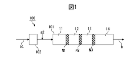
- the method includes a kneading step of kneading the first component and the second component by an extruder having a kneading zone including a plurality of narrow gap zones with a gap between the inner wall of the cylinder and the screw of 2 mm or less.
- the ratio of the gap [G1] of the narrowest gap zone, which has the smallest gap among the plurality of narrow gap zones, to the average value [G2] of the gaps of the narrow gap zones other than the narrowest gap zone [G1/G2] is 0.001 or more and less than 1.
- [3] The ratio of the gap [G1] of the narrowest gap zone having the smallest gap among the plurality of narrow gap zones to the gap [G3] of each of the narrow gap zones other than the narrowest gap zone [ G1/G3] is 0.001 or more and less than 1.
- the second component comprises an organic fiber;
- the organic fibers supplied to the extruder have an average fiber length of 1 ⁇ m to 10000 ⁇ m, Any of the above aspects 1 to 3, wherein the ratio of the gap [G1] of the narrowest gap zone, which has the smallest gap among the plurality of narrow gap zones, to the average fiber length is 0.001 to 10.
- the second component comprises an organic fiber;
- the organic fibers supplied to the extruder form particles with an average particle size of 1 ⁇ m to 10000 ⁇ m, Any one of the above aspects 1 to 4, wherein the ratio of the gap [G1] of the narrowest gap zone having the smallest gap among the plurality of narrow gap zones to the average particle size is 0.001 to 10.
- the method comprises a kneading step of kneading the first component and the second component with an extruder having a kneading zone including a pressure drop zone,
- the pressure drop zone has an inlet pressure of 0.5 to 20 MPa, and a ratio of the pressure of the outlet from the pressure drop zone to the pressure of the inlet to the pressure drop zone. 0.2 or less,
- a method wherein the content of said second component in the influent to said pressure drop zone is between 15 and 90% by weight.
- a method for producing a resin composition containing a first component and a second component the first component is a polymer, the second component is an organic fiber, a polymer different from the first component, or a combination thereof;
- the method comprises a kneading step of kneading the first component and the second component with an extruder having a kneading zone including a pressure drop zone,
- the pressure drop zone has an inlet pressure of 0.5 to 20 MPa, and a ratio of the pressure of the outlet from the pressure drop zone to the pressure of the inlet to the pressure drop zone.
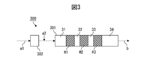
- the method includes a kneading step of kneading the first component and the second component by an extruder equipped with a kneading zone including a plurality of high pressure zones with a pressure of 0.1 MPa or more,
- the pressure [P1] of the highest pressure zone having the maximum pressure among the plurality of high pressure zones is 0.5 MPa or more, and the pressure [P1] is an average of the pressures of the high pressure zones other than the highest pressure zone.
- the method wherein the ratio [P1/P2] to the value [P2] is greater than 1 and 100 or less.
- the method according to aspect 12 wherein the ratio [P1/P3] of the pressure [P1] to the pressure [P3] of each of the high pressure zones other than the highest pressure zone is more than 1 and 100 or less.
- the method according to aspect 12 or 13 wherein the zone length/cylinder inner diameter ratio of each of the plurality of high pressure zones is 1-30.
- Any one of aspects 12 to 14 above, wherein the ratio of the zone length/cylinder inner diameter ratio of the highest pressure zone to the zone length/cylinder inner diameter ratio of each of the high pressure zones other than the highest pressure zone is 1 or more. described method.
- the method comprises a dispersive mixing step of dispersively mixing the first component and the second component in a dispersive mixing zone of an extruder;
- the method comprises a dispersive mixing step of dispersively mixing the first component and the second component in a dispersive mixing zone of an extruder; In the dispersive mixing zone, by varying one or more selected from the group consisting of zone length/cylinder inner diameter ratio, mixture filling rate, temperature, pressure, and space volume fraction in the cylinder length direction, the mixture advances in the cylinder.
- ⁇ M (GPa) per 1/d of tensile elongation change ⁇ E (%) per value (l/d) obtained by dividing length l (mm) by cylinder inner diameter d (mm) A method in which the ratio [ ⁇ E/ ⁇ M] to is varied in the cylinder length direction.
- the concentration [CA] of the second component in the dispersive mixing zone is 10% to 90% by mass, the concentration [CB] of the second component in the distributive mixing zone is 1% to 50% by mass,
- the method, wherein the ratio [CA]/[CB] is 2-90.
- the method comprises a dispersive mixing step of dispersively mixing the first component and the second component in a dispersive mixing zone of an extruder;
- the method comprises a dispersive mixing step of dispersively mixing the first component and the second component in a dispersive mixing zone of an extruder; In the dispersive mixing zone, by varying one or more selected from the group consisting of zone length/cylinder inner diameter ratio, mixture filling rate, temperature, pressure, and space volume fraction in the cylinder length direction, the mixture advances in the cylinder.
- the method comprising: a dispersive mixing step of dispersively mixing the first component and the second component in a dispersive mixing zone of the extruder to obtain a dispersive mixing product; a distributive mixing step of distributively mixing at least the dispersive mixing product in a distributive mixing zone of an extruder to obtain a resin composition; including The dispersive mixing zone and the distributive mixing zone differ from each other in one or more selected from the group consisting of zone length/cylinder inner diameter ratio, mixture filling rate, temperature, pressure, and spatial volume fraction; incremental tensile elongation [EA] of effluent from said dispersive mixing zone relative to tensile elongation of influent to said distributive mixing zone and from said distributive mixing zone relative to tensile elongation of influent to said distributive mixing zone The increment of tensile elongation [EB] of the effluent satisfies the relationship [EA] > [EB], increment of the flexural modulus of the outflow from the
- the method comprising: a dispersive mixing step of dispersively mixing the first component and the second component in a dispersive mixing zone of the extruder to obtain a dispersive mixing product; a distributive mixing step of distributively mixing at least the dispersive mixing product in a distributive mixing zone of an extruder to obtain a resin composition; including
- the concentration [CA] of the second component in the dispersive mixing zone is 10% to 90% by mass, the concentration [CB] of the second component in the distributive mixing zone is 1% to 50% by mass, 21.
- a method for producing a resin composition capable of forming a molded article having excellent tensile elongation and/or rigidity, more preferably a molded article having both high tensile elongation and rigidity and stably. can be provided.
- FIG. 2 is a diagram illustrating the steps of the method for producing a resin composition according to the first embodiment of Aspect A of the present invention.
- FIG. 4 is a diagram illustrating steps of a method for producing a resin composition according to a second embodiment of Aspect A of the present invention.
- FIG. 4 is a diagram illustrating steps of a method for producing a resin composition according to a third embodiment of Aspect A of the present invention.
- FIG. 2 is a diagram illustrating the steps of the method for producing a resin composition according to the first embodiment of Aspect B of the present invention.
- FIG. 4 is a diagram illustrating change behavior of tensile elongation and flexural modulus in the method according to the first embodiment of Aspect B of the present invention.
- FIG. 4 is a diagram illustrating steps of a method for producing a resin composition according to a second embodiment of Aspect B of the present invention.
- FIG. 10 is a diagram illustrating change behavior of tensile elongation and bending elastic modulus in the method according to the second embodiment of Aspect B of the present invention.
- FIG. 4 is a diagram illustrating steps of a method for producing a resin composition according to Aspect C of the present invention.
- present embodiments Exemplary embodiments of the present invention (hereinafter abbreviated as "present embodiments") will be described below, but the present invention is in no way limited to these embodiments.
- characteristic values of the present disclosure are values measured by the method described in the [Examples] section of the present disclosure or a method understood to be equivalent thereto by those skilled in the art.
- One aspect of the present disclosure provides a method for producing a resin composition containing a first component and a second component.
- the first component is a polymer and the second component is an organic fiber, polymer, or a combination thereof.
- the polymer in the second component is different than the first component.
- the first component constitutes the continuous phase in the resin composition.
- the organic fibers that the second component may contain are dispersed throughout the first component in the resin composition.
- the polymer that the second component may contain is present as a dispersed phase in the continuous phase of the first component in the resin composition.
- the method of the present disclosure includes a kneading step of kneading the first component and the second component by an extruder equipped with a kneading zone.
- a kneading step of kneading the first component and the second component by an extruder equipped with a kneading zone.
- the kneading conditions be designed so as not to impose an excessive load on the second component, which is necessary for the refinement of the second component.
- the first component and the second component are kneaded in a kneading zone controlled to specific kneading conditions.
- a partial area within the kneading zone is a zone where a large force is applied to the mixture.
- a region that mainly improves the tensile elongation and a region that mainly improves the bending and a region for improving the modulus of elasticity in the dispersive mixing zone, among the tensile elongation and the flexural modulus of the mixture, a region that mainly improves the tensile elongation and a region that mainly improves the bending and a region for improving the modulus of elasticity.
- dispersive mixing means a form of mixing that involves a substantial size change of the second component (disintegration of aggregates, cutting, fibrillation, etc.), and distributive mixing refers to the mixing of the second component. It means a mixed form in which the state of dispersion in the first component changes while the second component does not change substantially in size.
- a substantial size change is a size change of 30% or more relative to 100% of the original size in at least one size index.
- the second component is uniformly finely dispersed in the first component while avoiding damage to the second component due to the contribution of the unique kneading form as described above. It is possible to
- the second component is added to the first in the form of a dry mass or a slurry (e.g., an aqueous dispersion). may be melt-kneaded with the components of In a preferred embodiment, the second component is fed to the extruder in dry form.
- the heating temperature throughout melt-kneading is preferably above the glass transition point of the first component but not significantly above the glass transition point and/or melting point.
- the glass transition point is measured at an applied frequency of 10 Hz while increasing the temperature from 23 ° C. at a rate of 2 ° C./min using a dynamic viscoelasticity measuring device. is the peak top temperature of the peak at which the loss elastic modulus is maximized. When two or more loss modulus peaks appear, the peak top temperature of the peak on the highest temperature side is indicated.
- the melting point refers to the peak top temperature of the endothermic peak that appears when the temperature is raised from 23 ° C. at a rate of 10 ° C./min using a differential scanning calorimeter (DSC). When two or more appear, it indicates the peak top temperature of the endothermic peak on the highest temperature side.
- DSC differential scanning calorimeter
- the moisture content of the polymer to be melt-kneaded is preferably 0.2% by mass or less, 0.1% by mass or less, or 0.07% by mass or less.
- the moisture content may be, for example, 0.001% by mass or more from the viewpoint of ease of process control.
- a single-screw extruder or a twin-screw extruder may be used for melt-kneading, and the twin-screw extruder is preferable for controlling the dispersibility of the second component.
- L/D obtained by dividing the cylinder length (L) of the extruder by the screw diameter (D) is preferably 40 or more, particularly preferably 50 or more.
- the screw rotation speed during kneading is preferably in the range of 100 to 800 rpm, more preferably in the range of 150 to 600 rpm. These will vary depending on the screw design.
- Each screw in the cylinder of the extruder is optimized by combining an elliptical two-wing screw-shaped full-flight screw, a kneading element called a kneading disk, and the like.
- the screw element may have notches or flow diverting structures.
- a damming structure called a seal ring may also be arranged in the screw construction.
- the screw cross section may be composed of multiple cross sections such as 0, 1, 2, 3, and 4 threads. Moreover, these screw cross sections may have an eccentric shape.
- a partial region in the kneading zone is a zone where a large force is applied to the mixture (also referred to as a high load zone in the present disclosure) (more specifically, a narrow gap zone described later, pressure drop zone or high pressure zone).
- a high load zone in the present disclosure
- the high-load zone achieves refinement of the second component that can greatly contribute to improving the desired physical properties of the resin composition, while the other zone , the mixing conditions can be moderated to minimize the forces on the second component to avoid damage to the second component.
- the second component can be uniformly finely dispersed in the first component while avoiding damage to the second component, so in one aspect, the tensile elongation and / or It is possible to produce a resin composition capable of forming a molded article having excellent flexural modulus, more preferably a molded article having high and stable both tensile elongation and flexural modulus.
- Aspect A more specifically includes the following first to third embodiments.
- a first embodiment includes a kneading step of kneading the first component and the second component by an extruder equipped with a kneading zone including a plurality of narrow gap zones in which the gap between the inner wall of the cylinder and the screw is 2 mm or less. I will provide a.
- FIG. 1 is a diagram explaining the steps of the method for producing a resin composition according to the first embodiment.
- the extruder 100 comprises a kneading zone 101 and optionally a melting zone 102 .
- the second component a2 is added to the melt obtained by melting the first component a1 in the melting zone 102 to form a preliminary mixture. and the premix may be fed to the kneading zone 101 .
- the material to be mixed is strongly sheared in the initial melting zone, so that after the first component passes through the melting zone, the second component is applied to the molten first component.
- the component is added from the addition port (side feeder), thermal deterioration of the second component can be suppressed.
- the mixture is kneaded in kneading zone 101 and taken out as resin composition b.
- the kneading zone 101 includes a plurality of narrow gap zones N1, N2, N3 in which the gap between the cylinder inner wall and the screw (also referred to as cylinder gap in the present disclosure) is 2 mm or less.
- the cylinder gap means the gap of the widest channel among the channels through which the material to be mixed can pass from the upstream side to the downstream side of the extruder.
- the gap in the short axis direction of the radial cross section of the screw is defined as the cylinder gap.
- the gap between the screw and the cylinder is the cylinder gap.
- FIG. 1 shows an example in which there are three narrow gap zones, the number of narrow gap zones in the kneading zone may be selected according to the purpose. For example, it may be 10 or less, or 5 or less.
- the cylinder gap [G1] of the narrowest gap zone having the smallest cylinder gap is a narrow gap other than the narrowest gap zone
- the ratio [G1/G2] to the average value [G2] of the cylinder gap of the zone is 0.001 or more, or 0.01 or more, or It is 0.1 or more, and from the viewpoint of suppressing damage to the second component, in one aspect, it is less than 1, or 0.5 or less, or 0.3 or less.
- the average value [G2] means the cylinder clearance value of the zone if there is one zone, and means the arithmetic mean of the cylinder clearance values of the zone if there are two or more.
- the ratio [G1/G3] of [G1] to the cylinder gap [G3] of each of the narrow gap zones other than the narrowest gap zone is, in one aspect, 0.001 or more, or 0.01 or more, or 0.1 or more, and from the viewpoint of suppressing damage to the second component, in one aspect, less than 1, or 0.5 or less, or 0.3 or less be.
- [G1] is preferably 0.001 mm or more, or 0.01 mm or more, or 0.05 mm or more, and preferably 2 mm or less, or 1 mm or less, or 0.5 mm or less.
- [G2] is preferably 0.001 mm or more, or 0.01 mm or more, or 0.05 mm or more, and preferably 2 mm or less, or 1 mm or less, or 0.5 mm or less.
- [G3] is preferably 0.001 mm or more, or 0.01 mm or more, or 0.05 mm or more, and preferably 2 mm or less, or 1 mm or less, or 0.5 mm or less.
- the organic fibers supplied to the extruder have an average fiber length of 1 ⁇ m to 10000 ⁇ m.
- the average fiber length in the present disclosure is a value measured with a scanning electron microscope (SEM) as described below.
- the average fiber length is, in one aspect, 1 ⁇ m or more, or 10 ⁇ m or more, or 50 ⁇ m or more, and in one aspect, 10000 ⁇ m or less, or 1000 ⁇ m or less, or 750 ⁇ m or less, or 600 ⁇ m or less.
- the ratio of [G1] to the average fiber length is preferably 0.001 or more, or 0.01 or more, or 0.1 or more from the viewpoint of suppressing damage to organic fibers, It is preferably 10 or less, 5 or less, or 1 or less from the viewpoint of favorably advancing the miniaturization of organic fibers.
- the organic fibers fed to the extruder form particles with an average particle size of 1 ⁇ m to 10000 ⁇ m.
- the average particle diameter of the particles is 1 ⁇ m or more, or 10 ⁇ m or more, or 50 ⁇ m or more, and in one aspect, it is 10000 ⁇ m or less, or 1000 ⁇ m or less, or 750 ⁇ m or less, or 500 ⁇ m or less.
- the ratio of [G1] to the average particle diameter of the particles is preferably 0.001 or more, or 0.01 or more, or 0.1 or more from the viewpoint of suppressing damage to organic fibers.
- the average particle size in the present disclosure is the d50 particle size measured with a powder tester (for example, powder tester manufactured by Hosokawa Micron Corporation, model number: PT-X).
- the content of the second component in the inflow to each narrow gap zone is determined from the viewpoint of obtaining the desired effect of improving the physical properties of the second component by including the second component in the resin composition at a desired concentration. Therefore, it is preferably 15% by mass or more, or 20% by mass or more, or 30% by mass or more, and from the viewpoint of favorably advancing the refinement of the second component, preferably 90% by mass or less, or 80% by mass % or less, or 70% by mass or less.
- the pressure of the inflow into each narrow gap zone is preferably 0.5 MPa or more, or 1 MPa or more, or 3 MPa or more from the viewpoint of favorably advancing the refinement of the second component. From the viewpoint of suppressing damage, it is preferably 20 MPa or less, 15 MPa or less, or 10 MPa or less. It should be noted that, in one aspect, the pressure of the influent into each narrow gap zone is substantially equal to the pressure of the mixture to be mixed within each narrow gap zone.
- the ratio of the pressure of the effluent from the narrow-gap zone to the pressure of the inflow into the narrow-gap zone is such that increasing the pressure of the influent to the narrow-gap zone causes the refinement of the second component. It is preferably 0.2 or less, or 0.15 or less, or 0.1 or less in terms of being able to proceed well, and suppresses damage to the second component due to sudden pressure changes in the mixture. from the point of view that it is preferably 0.0001 or more, or 0.001 or more, or 0.01 or more. It should be noted that in one aspect, the pressure of the effluent from each narrow gap zone is substantially equal to the mixed pressure in the zone adjacent downstream to each narrow gap zone. It should be noted that the inflow to each zone or the outflow from each zone may be a mixture that enters or exits from each zone. It is not limited to what is provided in advance.
- the pressure of the effluent from the narrow gap zone may in one aspect be 0 MPa or higher, or 0.001 MPa or higher, or 0.01 MPa or higher, and in one aspect 4 MPa or lower, or 2 MPa or lower. , or 1 MPa or less.
- a second embodiment provides a method comprising a kneading step of kneading a first component and a second component with an extruder having a kneading zone including a pressure drop zone.
- the pressure drop zone has an inlet pressure of 0.5 to 20 MPa and a ratio of the pressure of the outlet from the pressure drop zone to the pressure of the inlet to the pressure drop zone of 0. .2 or less.
- the pressure of the inflow into the pressure drop zone is preferably 0.5 MPa or more, or 1 MPa or more, or 3 MPa or more from the viewpoint of favorably advancing the refinement of the second component, and the second component is prevented from being damaged. is preferably 20 MPa or less, or 15 MPa or less, or 10 MPa or less. It should be noted that, in one aspect, the pressure of the inlet to the pressure drop zone is substantially equal to the mixture pressure in the pressure drop zone.
- the content of the second component in the inflow to the pressure drop zone is 15-90% by mass and/or the mixture after passing through the pressure drop zone in the kneading step has more Cold additional polymer is added to cool the mixture.
- the content of the second component in the inflow to the pressure drop zone is 15-90% by weight
- the pressure of the inflow to the pressure drop zone is 0.5-20 MPa
- the ratio of the pressure of the effluent from the pressure drop zone to the pressure of the inflow to the pressure drop zone is less than or equal to 0.2.
- the pressure of the inlet to the pressure drop zone is between 0.5 and 20 MPa and the ratio of the pressure of the outlet from the pressure drop zone to the pressure of the inlet to the pressure drop zone is 0.2 or less. and in the kneading step, the mixture is cooled by adding additional polymer having a lower temperature than the mixture after passing through the pressure drop zone.
- an extruder 200 comprises a kneading zone 201 and optionally a melting zone 202 .
- the second component a2 is added to the melt obtained by melting the first component a1 in the melting zone 202 before the kneading step in the kneading zone 201.
- a further step of obtaining a mixture may be included and a pre-mixture may be supplied to the kneading zone 201 .
- the material to be mixed is strongly sheared in the first melting zone.
- the second When the component is added from the addition port (side feeder), thermal deterioration of the second component can be suppressed.
- the mixture is kneaded in kneading zone 201 and taken out as resin composition b.
- the kneading zone 201 in the second embodiment includes a pressure drop zone D1.
- FIG. 2 shows an example in which there is one pressure drop zone D1, in the second embodiment, the number of pressure drop zones may be selected according to the purpose. 2 or more, or 3 or more, and in one aspect, 10 or less, or 5 or less.
- the pressure drop zone in the second embodiment may, in one aspect, be the narrow gap zone described in the first embodiment.
- the cylinder gap of the narrow gap zone may be the same as exemplified in the first embodiment.
- the pressure drop zone adjusts one or more selected from the group consisting of zone length/cylinder inner diameter ratio, mixture filling rate, temperature, pressure, screw rotation speed, feed amount, resin composition, and space volume fraction of the present disclosure. may be formed by
- FIG. 3 is a diagram illustrating steps of a method for producing a resin composition according to the third embodiment.
- the method according to the third embodiment has the following features, it is possible to combine one or more of the features exemplified above for the first or second embodiment except for the features.
- an extruder 300 comprises a kneading zone 301 and optionally a melting zone 302 .
- the melt obtained by melting the first component a1 in the melting zone 202 is fed with the second component a2 by side feeding, for example. to obtain a pre-mixture, and the pre-mixture may be fed to the kneading zone 301 .
- Such an addition mode is preferable from the viewpoint of suppressing thermal deterioration of the second component.
- the mixture is kneaded in kneading zone 301 and taken out as resin composition b.
- the kneading zone 301 includes a plurality of high pressure zones H1, H2, H3 with a pressure of 0.1 MPa or higher.
- FIG. 3 shows an example in which there are three high pressure zones, the number of high pressure zones in the kneading zone may be selected according to the purpose. or less, or 5 or less.
- the pressure [P1] of the highest pressure zone (hereinafter also simply referred to as [P1]) having the highest pressure, the average value of the pressures of the high pressure zones other than the highest pressure zone
- the ratio [P1/P2] to [P2] is greater than 1, or 1.5 or more, or 2 or more, from the viewpoint of favorably advancing the refinement of the second component. From the viewpoint of suppressing the damage of , in one aspect, it is 100 or less, or 50 or less, or 20 or less.
- the average value [P2] means the pressure value of the zone if there is one zone, and means the arithmetic mean of the pressure values of the zone if there are two or more.
- the ratio [P1/P3] of [P1] to the pressure [P3] of each of the high pressure zones other than the highest pressure zone is greater than 1, or It is 1.5 or more, or 2 or more, and from the viewpoint of suppressing damage to the second component, in one aspect, it is 100 or less, or 50 or less, or 20 or less.
- [P1] is 0.5 MPa or more, preferably 1 MPa or more, or 2 MPa or more, and preferably 20 MPa or less, or 15 MPa or less, or 10 MPa or less.
- [P2] is preferably 0.1 MPa or more, or 0.3 MPa or more, or 0.5 MPa or more, and preferably 20 MPa or less, or 15 MPa or less, or 10 MPa or less.
- [P3] is preferably 0.1 MPa or more, or 0.3 MPa or more, or 0.5 MPa or more, and preferably 20 MPa or less, or 15 MPa or less, or 10 MPa or less.
- the zone length/cylinder inner diameter ratio of each of the plurality of high-pressure zones is, in one aspect, 1 or more, 2 or more, or 4 or more, from the viewpoint of favorably advancing the refinement of the second component, and the second In one aspect, it is 30 or less, or 20 or less, or 15 or less, from the viewpoint of suppressing damage to components.
- the pressure of the highest pressure zone is 0.3 MPa or more, or 0.5 MPa or more, or 1 MPa or more from the viewpoint of favorably advancing the refinement of the second component, and damages the second component. From the viewpoint of suppression, in one aspect, it is 50 MPa or less, or 20 MPa or less, or 15 MPa or less.
- the kneading zones 101, 201, 301 may include dispersive mixing zones and distributive mixing zones.
- Narrow gap zones N1, N2, N3, pressure drop zone D1, and high pressure zones H1, H2, H3 are dispersive mixing zones.
- each of the other zones 11, 12, 13, 14, 21, 22, 31, 32, 33, 34 may be dispersive mixing zones or distributive mixing zones.
- the kneading conditions of other zones may be arbitrarily designed to be the same or different from each other as desired.
- the most downstream zone of the kneading zone is a miscellaneous zone (eg, miscellaneous zones 14, 22, 24 in FIGS. 1-3), preferably a distributive mixing zone.
- additional polymer ⁇ 1-3 in the method according to embodiment A, in the kneading zone 101, 201, 301, to the mixture is added an additional polymer of the same type or a different type, preferably the same type as the polymer in the mixture (e.g. side feed).
- the location of addition of additional polymer may be downstream of all narrow gap zones N1, N2, N3 of kneading zone 101 and downstream of pressure drop zone D1 of kneading zone 201. and downstream of all high pressure zones H1, H2, H3 of the kneading zone 301.
- the amount of the additional polymer to be added may be determined according to the kneading conditions, the desired concentration of the second component of the resin composition, and the like. or more, or 30 parts by mass or more, or 50 parts by mass or more, and may be 1000 parts by mass or less, or 500 parts by mass or less, or 400 parts by mass or less, or 300 parts by mass or less.
- the concentration of the second component of the mixture before the addition of the additional polymer is 10 wt% or more, or 15 wt% or more, or 20 wt% or more, or 25 wt% or more, or 30 wt% or more, and / Alternatively, 90% by mass or less, or 80% by mass or less, or 70% by mass or less, or 60% by mass or less, or 50% by mass or less, and the concentration of the second component of the mixture after addition of the additional polymer (one equivalent to the concentration of the second component in the resin composition) is 1% by mass or more, or 2% by mass or more, or 3% by mass or more, or 5% by mass or more, and/or 50% by mass or less. , or 40% by mass or less, or 30% by mass or less, or 20% by mass or less.
- the additional polymer may be cooler than the mixture. That is, in the kneading step, all of the plurality of narrow gap zones according to the first embodiment, or the pressure drop zones according to the second embodiment (if there are multiple, all of them in one aspect), or the third Additional polymer having a lower temperature than the mixture may be added to the mixture after passing through all of the plurality of high pressure zones according to the embodiment of (1) to cool the mixture.
- the temperature of the additional polymer added for cooling is, in one aspect, 0° C. or higher, or 10° C. or higher, or 20° C. or higher, and in one aspect, 300° C. or lower, or 200° C. or lower, or 100° C. or lower. , or 50° C. or less.
- the temperature of the mixture to which the additional polymer is added is, in one aspect, 100° C. or higher, or 150° C. or higher, or 200° C. or higher, and in one aspect, 450° C. or lower, or 400° C. or lower, or 350° C. or lower. .
- the rate of flexural modulus enhancement per unit mass of mixture in each of the high load zones which may be a plurality (i.e., the flexural modulus of the outflow from each zone to the ratio of flexural modulus) is the flexural modulus improvement rate per unit mass of mixture in each zone other than the high-load zone (i.e., the flexural modulus of outflow from each zone to the flexural modulus of inflow into each zone).
- ratio is greater than the maximum value.
- the ratio of the thixotropic index of the outflow from the kneading zone to the thixotropic index of the inflow into the kneading zone is preferably 1 or more from the viewpoint of uniform fine dispersion of the second component by the kneading zone. , or 2 or more, or 3 or more, and preferably 100 or less, or 50 or less, or 10 or less from the viewpoint of suppressing damage to the second component.
- the method according to aspect B of the present disclosure includes a dispersive mixing step of dispersively mixing the first component and the second component in a dispersive mixing zone of the extruder.
- the method according to Aspect B has the following features, but other than this feature, one or more of the features exemplified above with respect to Aspect A can be combined.
- the dispersive mixing zone according to aspect B may comprise a high load zone according to aspect A (more specifically a narrow gap zone, a pressure drop zone or a high pressure zone).
- a method for producing a resin composition containing a first component and a second component comprises a dispersive mixing step of dispersively mixing the first component and the second component in a dispersive mixing zone of an extruder; A first dispersive mixing zone and a second dispersive mixing zone in which at least one of the dispersive mixing zones is selected from the group consisting of zone length/cylinder inner diameter ratio, mixture filling rate, temperature, pressure, and spatial volume fraction is different from each other.
- the second component contains organic fibers, and the mass ratio of components with a diameter of 50 ⁇ m or more in the organic fibers in the inflow to the first dispersive mixing zone is 10% to 90%; A component with a diameter of 50 ⁇ m or more in the organic fiber in the outflow from the first dispersive mixing zone relative to a mass ratio (1a) of a component with a diameter of 50 ⁇ m or more in the organic fiber in the inflow to the first dispersive mixing zone The ratio (1b/1a) of the mass ratio (1b) of is 0 to 0.6, A component with a diameter of 50 ⁇ m or more in the organic fibers in the outflow from the second dispersive mixing zone relative to a mass ratio (2a) of a component with a diameter of 50 ⁇ m or more in the organic fibers in the inflow to the second dispersive mixing zone.
- the [E1] is 1% to 100%, the [E2] is 0% to 10%, the [M1] is 0 GPa to 1 GPa, the [M2] is 0.1 GPa to 20 GPa, and the [E1] Aspects 1 to 4 above, wherein the absolute value of the difference between [E2] is 0.1% to 100%, and the absolute value of the difference between [M1] and [M2] is 0.1 GPa to 20 GPa.
- Method. [6] The method according to any one of aspects 1 to 5, wherein the zone length/cylinder inner diameter ratio of each of the first dispersive-mixing zone and the second dispersive-mixing zone is 1-30.
- a method for producing a resin composition containing a first component and a second component comprises a dispersive mixing step of dispersively mixing the first component and the second component in a dispersive mixing zone of an extruder; In the dispersive mixing zone, by varying one or more selected from the group consisting of zone length/cylinder inner diameter ratio, mixture filling rate, temperature, pressure, and space volume ratio in the cylinder length direction, the mixture advances in the cylinder.
- ⁇ M Flexural modulus change
- the second component contains organic fibers, preferably cellulose fibers, and the organic fibers in the resin composition have an average fiber diameter of 1000 nm or less and an average fiber length/average fiber diameter ratio of 30 or more.
- a method according to any of aspects 1-12. further comprising, prior to the dispersive mixing step, adding the second component to the melt of the first component to obtain a premix, and feeding the premix to the dispersive mixing zone; The method according to any one of aspects 1 to 13 above.
- a region that mainly improves the tensile elongation (also referred to as a tensile elongation improving region in the present disclosure) and a region that mainly improves the tensile elongation
- a region for improving the flexural modulus (also referred to as a flexural modulus improving region in the present disclosure) is provided.
- the coarse agglomerates of the second component can be pulverized, thereby increasing the tensile elongation of the mixture, while pulverizing the coarse agglomerates increases the flexural modulus (i.e., stiffness) of the mixture. contribution to the increase in
- the second component in the flexural modulus enhancing region, can be finely dispersed in the first component, thereby increasing the flexural modulus of the mixture, while fine dispersion increases the tensile elongation of the mixture.
- one of the tensile elongation and the flexural modulus is increased in each of the tensile elongation improving region and the flexural modulus improving region, rather than trying to increase the tensile elongation and the flexural modulus at the same time. Focus on improving. According to the resin composition obtained through such a process, the tensile elongation and flexural modulus are unexpectedly higher than the resin composition obtained through the process of simultaneously increasing the tensile elongation and the flexural modulus. It is possible to achieve both high and stable flexural modulus. The above advantages can be pronounced when the second component comprises organic fibres, especially cellulose fibres. Aspect B more specifically includes the following first and second embodiments.
- FIG. 4 is a diagram for explaining the steps of the method for producing a resin composition according to the first embodiment, and FIG. 5 shows the change behavior of tensile elongation and flexural modulus in the method according to the first embodiment. It is a figure explaining.
- an extruder 400 in a first embodiment, has a dispersive mixing zone 401 .
- Extruder 400 may further have a distributive mixing zone 402 .
- Extruder 400 may also have a melt zone 403 upstream of dispersive mixing zone 401 and/or a melt zone 404 downstream of dispersive mixing zone 401 .
- the method of the present disclosure adds the second component a2 to the melt obtained by melting the first component a1 in the melting zone 403 to form a premix prior to the dispersive mixing step in the dispersive mixing zone 401.
- a premix may be provided to the dispersive mixing zone 401 .
- the second component is added to the molten first component after the resin has passed through the melting zone. When adding from the mouth (side feeder), thermal deterioration of the second component can be suppressed.
- the mixture is dispersively mixed and optionally distributed mixed in an extruder 400 and taken out as a resin composition b.
- the method according to aspect B further comprises adding to the dispersive mixing product after the dispersive mixing step and before the distributive mixing step an additional polymer of the same or different, preferably the same type as the first component in the dispersive mixing product.
- the step of adding to obtain an additional polymer mixture may be further included, and the additional polymer mixture may be fed to the distributive mixing zone.
- additional polymer may be added to the effluent from dispersive mixing zone 401 (eg, by side-feeding additional polymer in melt zone 404 in FIG. 4) before being fed to distributive mixing zone 402 .
- the amount of the additional polymer to be added may be determined according to the kneading conditions, the desired concentration of the second component of the resin composition, etc.
- 10 parts by mass or more with respect to 100 parts by mass of the dispersed mixture product may be 20 parts by weight or more, or 30 parts by weight or more, or 50 parts by weight or more, and may be 1000 parts by weight or less, or 500 parts by weight or less, or 400 parts by weight or less, or 300 parts by weight or less.
- the concentration of the second component of the dispersed mixture product is 10 wt% or more, or 20 wt% or more, or 25 wt% or more, or 30 wt% or more, and/or 80 wt% or less, or 70% by mass or less, or 60% by mass or less, or 50% by mass or less, and the concentration of the second component of the additional polymer mixture (in one aspect, equal to the concentration of the second component in the resin composition) 1% by mass or more, or 2% by mass or more, or 3% by mass or more, or 5% by mass or more, and/or 50% by mass or less, or 40% by mass or less, or 30% by mass or less, or 20% by mass It can be:
- the additional polymer may be cooler than the dispersed mixture product, thereby cooling the dispersed mixture product.
- the temperature of the additional polymer added for cooling is, in one aspect, 0° C. or higher, or 10° C. or higher, or 20° C. or higher, and in one aspect, 300° C. or lower, or 200° C. or lower, or 100° C. or lower. , or 50° C. or less.
- the temperature of the dispersed mixture product to which the additional polymer is added is, in one aspect, 100°C or higher, or 150°C or higher, or 200°C or higher, and in one aspect, 450°C or lower, or 400°C or lower, or 350°C. It is below.
- the dispersive mixing zone 401 comprises a first dispersive mixing zone 41 and a second dispersive mixing zone 42 with different process conditions.
- the first dispersive mixing zone 41 and the second dispersive mixing zone 42 are in direct communication with each other.
- upstream of the first dispersive mixing zone 41, between the first dispersive mixing zone 41 and the second dispersive mixing zone 42, and/or downstream of the second dispersive mixing zone 42, additional dispersive Mixed zones may be present.
- a third dispersive mixing zone (not shown) configured the same as or different from the first dispersive mixing zone 41 or the second dispersive mixing zone 42;
- a configuration can be exemplified in which the effluent from the third dispersive mixing zone is recovered as the resin composition b.
- the process conditions are one or more selected from the group consisting of zone length/cylinder inner diameter ratio, mixture filling rate, temperature, pressure, and spatial volume fraction.
- the above zone length is the total length of the screw elements that make up the dispersive mixing zone and the distributive mixing zone, and depends on the screw configuration.
- the above-mentioned mixture filling rate is the ratio of the actual filling amount (volume basis) of the mixture to the space volume of the extruder, and after suddenly stopping the rotation of the screw and the supply of raw materials, the screw is pulled out and adheres to the screw surface.
- the filled mixture is sampled, weighed, and divided by the density of the mixture to calculate the volume of the filled mixture, followed by dividing the volume of the filled mixture by the spatial volume described below to calculate the mixture fill factor.
- Mixture fill factor is dependent on screw configuration and extrusion conditions.
- the above space volume ratio is calculated by subtracting the screw volume (sum of element volume and shaft volume) from the cylinder volume of the extruder to calculate the space volume, and dividing the space volume by the cylinder volume.
- the spatial volume fraction depends on the screw configuration.
- the increment [M1] of the flexural modulus of the effluent 41b from the first dispersive mixing zone with respect to the flexural modulus of the inflow 41a to the first dispersive mixing zone and the inflow to the second dispersive mixing zone The increment [M2] of the flexural modulus of the effluent 42b from the second dispersive mixing zone with respect to the flexural modulus of 42a satisfies the relationship [M1] ⁇ [M2]. That is, the first dispersive mixing zone is a tensile elongation improving region, and the second dispersive mixing zone is a flexural modulus improving region.
- the first dispersive mixing zone 41 and the second dispersive mixing zone 42 are in communication (in one aspect, the direct communication). Such arrangement is advantageous from the viewpoint of further improving the elastic modulus.
- the first and second dispersive-mixing zones may communicate (in one aspect, direct communication) so that the second dispersive-mixing zone is on the upstream side.
- Such arrangement is advantageous from the viewpoint of further improving elongation.
- the inflow to each zone or the outflow from each zone may be a mixture that enters or exits from each zone. It is not limited to what is provided in advance.
- the mass ratio of the components with a diameter of 50 ⁇ m or more in the organic fibers in the inflow 41a to the first dispersive mixing zone is preferably 10% or more, or It is 20% or more, or 30% or more, or 40% or more, preferably 90% or less, or 80% or less, or 70% or less, or 60% or less. That is, the influent 41a may contain a substantial amount of coarse particles.
- the mass ratio (1a) of the components with a diameter of 50 ⁇ m or more in the organic fibers in the first dispersive mixing zone inflow 41a in the organic fibers in the outflow 41b from the first dispersive mixing zone is preferably 0 or more, or 0.1 or more, or 0.2 or more, and preferably 0.6 or less, or 0 .5 or less, or 0.3 or less.
- coarse particles are pulverized in the first dispersive mixing zone 41, and coarse particles are greatly reduced in the effluent 41b.
- the ratio of the weight ratio (2a) of the 50 ⁇ m or larger diameter component in the organic fibers in the second dispersive mixing zone inflow 42a to the organic fibers in the second dispersive mixing zone effluent 42b is
- the ratio (2b/2a) of the mass ratio (2b) of the component with a diameter of 50 ⁇ m or more is preferably 0.6 or more, or 0.7 or more, or 0.8 or more, and preferably 1 or less, or 0 .9 or less.
- the ratio (2b/2a) is treated as 1 when both the mass ratios (2a) and (2b) are 0%.
- [E1] is preferably 1% or more, or 2% or more, or 3% or more, preferably 100% or less, or 50% or less, or 30% or less
- [E2 ] is preferably 0% or more, preferably 10% or less, or 5% or less, or 3% or less
- [M1] is preferably 0 GPa or more, or 0.1 GPa or more, or 0 .3 GPa or more, preferably 1 GPa or less, or 0.7 GPa or less, or 0.5 GPa or less
- [M2] is preferably 0.1 GPa or more, or 0.5 GPa or more, or 1 GPa or more , preferably 20 GPa or less, or 10 GPa or less, or 5 GPa or less
- the absolute value of the difference between [E1] and [E2] is preferably 0.1% or more, or 1% or more, or 5% or more Yes, preferably 100% or less, or 50% or less, or 30% or less
- the zone length/cylinder inner diameter ratio of each of the first and second dispersive mixing zones is preferably 1 or more, or 3 or more, or 4 or more, and preferably 30 or less, or 20 or less. , or 10 or less.
- the mixture fill factor of each of the first and second dispersive mixing zones is preferably 10% or more, or 50% or more, or 70% or more, preferably 100% or less, or 99%. % or less, or 95% or less.
- the temperature of each of the first and second dispersive mixing zones is preferably 100°C or higher, or 150°C or higher, or 200°C or higher, preferably 400°C or lower, or 350°C or lower. , or 300° C. or less.
- the mixed pressure in each of the first and second dispersive mixing zones is preferably 0 MPa or higher, or 0.1 MPa or higher, or 0.3 MPa or higher, or 1 MPa or higher, preferably 15 MPa. or less, or 10 MPa or less, or 5 MPa or less, or 3 MPa or less.
- the spatial volume fraction of each of the first and second dispersive mixing zones is preferably 10% or more, or 20% or more, or 30% or more, and preferably 70% or less, or 60% or more. % or less, or 50% or less.
- the resin composition dispersed and mixed in the dispersive mixing zone 401 may be introduced into the distributive mixing zone 402 with or without passing through another zone (for example, the melting zone 404) for further distributive mixing.
- Mixing conditions in the distributive mixing zone are not particularly limited, but distributive mixing may be performed by arbitrarily combining kneading disks such as progressive kneading disks and neutral kneading disks.
- FIG. 6 is a diagram for explaining the steps of the method for producing a resin composition according to the second embodiment
- FIG. 7 shows the change behavior of tensile elongation and flexural modulus in the method according to the second embodiment. It is a figure explaining.
- the method according to the second embodiment has the following features, but other than the features, the same procedures and conditions as those described above for the first embodiment may be appropriately employed.
- an extruder 600 has a dispersive mixing zone 601 and may optionally further have a distributive mixing zone 602, a melt zone 603 upstream of the dispersive mixing zone 601, and/or may further include a melt zone 604 downstream of the dispersive mixing zone 601 .
- the second component a2 is added to the melt obtained by melting the first component a1 in the melting zone 603 before the dispersive mixing step in the dispersive mixing zone 601 to form a preliminary mixture. and the premix may be fed to the dispersive mixing zone 601 .
- the mixture is dispersively mixed and optionally distributed mixed in an extruder 600 and taken out as a resin composition b.
- the dispersive mixing zone 601 has a length of in-cylinder travel l of the mixture (i.e., a flow length in the cylinder length direction L as the mixture flows through the dispersive mixing zone 601) due to different process conditions.
- the amount of change in tensile elongation ⁇ E (%) per value (l/d) obtained by dividing the length) (mm) by the cylinder inner diameter d (mm) with respect to the amount of change in flexural modulus ⁇ M (GPa) per l/d
- the ratio [ ⁇ E/ ⁇ M] is varied in the longitudinal direction L of the cylinder.
- the process conditions are one or more selected from the group consisting of zone length/cylinder inner diameter ratio, mixture fill factor, temperature, pressure, and void volume fraction.
- the ratio [ ⁇ E/ ⁇ M] is gradually decreased from upstream to downstream of the cylinder.
- the more upstream side of the cylinder corresponds to the tensile elongation improvement region, and the more downstream side corresponds to the flexural modulus improvement region, which is advantageous in that a resin composition with higher rigidity can be obtained.
- ⁇ E may gradually decrease and ⁇ M may gradually increase from the upstream side to the downstream side of the cylinder.
- ⁇ E is 0.1% or more, or 1% or more, or 10% or more, and 300% or less, or 200% or less, or 100% or less.
- range may be tapered to a range of 0.01% or more, or 0.1% or more, or 0.5% or more, and 10% or less, or 5% or less, or 2% or less, wherein ⁇ M is 0.001 GPa or more, or 0.01 GPa or more, or 0.05 GPa or more, and 10 GPa or less, or 5 GPa or less, or 2 GPa or less, to 0.02 GPa or more, or 0.05 GPa or more, or 0.1 GPa or more and may be gradually increased to a range that is 50 GPa or less, or 10 GPa or less, or 5 GPa or less.
- the ratio [ ⁇ E/ ⁇ M] is gradually increased from upstream to downstream of the cylinder.
- the more upstream side of the cylinder corresponds to the flexural modulus improving region, and the more downstream side corresponds to the tensile elongation improving region, which is advantageous in that a resin composition with higher elongation can be obtained.
- ⁇ E may gradually increase and ⁇ M may gradually decrease from upstream to downstream of the cylinder.
- ⁇ E is 0.01% or more, or 0.1% or more, or 0.5% or more, and 10% or less, or 5% or less, or 2% or less, may be gradually increased to a range of 0.1% or more, or 1% or more, or 10% or more, and 300% or less, or 200% or less, or 100% or less, and ⁇ M is 0 .02 GPa or more, or 0.05 GPa or more, or 0.1 GPa or more, 50 GPa or less, or 10 GPa or less, or 5 GPa or less, to 0.001 GPa or more, or 0.01 GPa or more, or 0.05 GPa or more Yes, and may be gradually decreased to a range of 10 GPa or less, or 5 GPa or less, or 2 GPa or less.
- a method according to aspect C of the present disclosure comprises a dispersive mixing step of dispersively mixing a first component and a second component in a dispersive mixing zone of an extruder to obtain a dispersive mixing product; and a distributive mixing step of distributively mixing at least the dispersive mixing product to obtain a resin composition.
- the method according to Aspect C has the following features, but one or more of the features exemplified above with respect to Aspect A can be combined in addition to these features.
- the dispersive mixing zone according to aspect C may comprise a high load zone according to aspect A (more specifically a narrow gap zone, a pressure drop zone or a high pressure zone).
- a method for producing a resin composition containing a first component and a second component comprising: a dispersive mixing step of dispersively mixing the first component and the second component in a dispersive mixing zone of the extruder to obtain a dispersive mixing product; a distributive mixing step of distributively mixing at least the dispersive mixing product in a distributive mixing zone of an extruder to obtain a resin composition; including The dispersive mixing zone and the distributive mixing zone differ from each other in one or more selected from the group consisting of zone length/cylinder inner diameter ratio, mixture filling rate, temperature, pressure, and spatial volume fraction; Incremental tensile elongation [EA] of effluent from said dispersive mixing zone relative to tensile elongation of influent to said distributive mixing zone and from said distributive mixing zone relative to tensile elongation of influent to said distributive mixing zone The increment of tensile elongation [EB] of the effluent satisfies the relationship
- the [EA] is 1% to 100%, the [EB] is 0% to 10%, the [MA] is 0.1 GPa to 20 GPa, the [MB] is 0 GPa to 1 GPa, [EA] and [ EB] and the difference ([EA] - [EB]) is 0.01% to 100%, and the difference between [MA] and [MB] ([MA] - [MB]) is 0.001GPa to 10GPa.
- a method for producing a resin composition containing a first component and a second component comprising: a dispersive mixing step of dispersively mixing the cellulose fibers and the resin in the dispersive mixing zone of the extruder to obtain a dispersed mixed product; a distributive mixing step of distributively mixing at least the dispersive mixing product in a distributive mixing zone of an extruder to obtain a resin composition; including
- the concentration [CA] of the second component in the dispersive mixing zone is from 10% to 90% by weight
- the concentration [CB] of the second component in the distributive mixing zone is from 1% to 50% by weight
- the ratio [ CA]/[CB] is 2-90.
- FIG. 8 is a diagram explaining steps of a method for producing a resin composition according to one embodiment of the present invention.
- extruder 800 has dispersive mixing zone 801 and distributive mixing zone 802 .
- a distributive mixing zone 802 is positioned downstream of the dispersive mixing zone 801, as shown in FIG.
- the extruder 800 may also have a melt zone 803 upstream from the dispersive mixing zone 801 and/or a melt zone 804 downstream from the dispersive mixing zone 801 and upstream from the distributive mixing zone 802. .
- the second component a2 is added to the melt obtained by melting the first component a1 in the melting zone 803 before the dispersive mixing step in the dispersive mixing zone 801 to obtain a preliminary mixture.
- a further step may be included wherein the premix may be fed to the dispersive mixing zone 801 .
- the material to be mixed is strongly sheared in the initial melting zone, so that after the first component passes through the melting zone, the second component is applied to the molten first component.
- the component is added from the addition port (side feeder), thermal deterioration of the second component can be suppressed.
- the mixture is dispersively mixed and distributed mixed in an extruder 800 and taken out as a resin composition b.
- the method according to aspect C further comprises adding to the dispersive mixing product after the dispersive mixing step and before the distributive mixing step an additional polymer of the same or different, preferably the same type as the first component in the dispersive mixing product.
- the step of adding to obtain an additional polymer mixture may be further included, and the additional polymer mixture may be fed to the distributive mixing zone.
- additional polymer may be added to the effluent from dispersive mixing zone 801 (eg, by side-feeding additional polymer in melt zone 804 in FIG. 8) before being fed to distributive mixing zone 802 .
- the amount of the additional polymer to be added may be determined according to the kneading conditions, the desired concentration of the second component of the resin composition, etc.
- 10 parts by mass or more with respect to 100 parts by mass of the dispersed mixture product may be 20 parts by weight or more, or 30 parts by weight or more, or 50 parts by weight or more, and may be 1000 parts by weight or less, or 500 parts by weight or less, or 400 parts by weight or less, or 300 parts by weight or less.
- the concentration of the second component of the dispersed mixture product is 10 wt% or more, or 20 wt% or more, or 25 wt% or more, or 30 wt% or more, and/or 80 wt% or less, or 70% by mass or less, or 60% by mass or less, or 50% by mass or less, and the concentration of the second component of the additional polymer mixture (in one aspect, equal to the concentration of the second component in the resin composition) 1% by mass or more, or 2% by mass or more, or 3% by mass or more, or 5% by mass or more, and/or 50% by mass or less, or 40% by mass or less, or 30% by mass or less, or 20% by mass It can be:
- the additional polymer may be cooler than the dispersed mixture product, thereby cooling the dispersed mixture product.
- the temperature of the additional polymer added for cooling is, in one aspect, 0° C. or higher, or 10° C. or higher, or 20° C. or higher, and in one aspect, 300° C. or lower, or 200° C. or lower, or 100° C. or lower. , or 50° C. or less.
- the temperature of the dispersed mixture product to which the additional polymer is added is, in one aspect, 100°C or higher, or 150°C or higher, or 200°C or higher, and in one aspect, 450°C or lower, or 400°C or lower, or 350°C. It is below. Aspect C more specifically includes the following first and second embodiments.
- the dispersive mixing zone 801 and the distributive mixing zone 802 differ from each other in process conditions.
- the process conditions are one or more selected from the group consisting of zone length/cylinder inner diameter ratio, mixture fill factor, temperature, pressure, and void volume fraction.
- the above zone length is the total length of the screw elements that make up the dispersive mixing zone and the distributive mixing zone, and depends on the screw configuration.
- the above-mentioned mixture filling rate is the ratio of the actual filling amount (volume basis) of the mixture to the space volume of the extruder, and after suddenly stopping the rotation of the screw and the supply of raw materials, the screw is pulled out and adheres to the screw surface.
- the filled mixture is sampled, weighed, and divided by the density of the mixture to calculate the volume of the filled mixture, followed by dividing the volume of the filled mixture by the spatial volume described below to calculate the mixture fill factor.
- Mixture fill factor is dependent on screw configuration and extrusion conditions.
- the space volume ratio is calculated by subtracting the screw volume (the sum of the element volume and the shaft volume) from the barrel volume of the extruder to calculate the space volume, and then dividing the space volume by the barrel volume.
- the spatial volume fraction depends on the screw configuration.
- the incremental tensile elongation [EA] of the effluent from the dispersive mixing zone 801 relative to the tensile elongation of the influent to the dispersive mixing zone 801 and the tensile elongation of the influent to the distributive mixing zone 802 are
- the incremental tensile elongation [EB] of the outflow from the distributive mixing zone 802 satisfies the relationship [EA]>[EB] and the flexural modulus of the inflow of the dispersive mixing zone 801 from the dispersive mixing zone 801 to the flexural modulus of the inflow of 801 into the dispersive mixing zone and the flexural modulus increment of the outflow from the distributive-mixing zone 802 with respect to the flexural modulus of the inflow into the distributive-mixing zone 802 [MB] is given by [MA] > satisfies the relationship of [MB].
- the inflow to each zone or the outflow from each zone may be a mixture that enters or exits from each zone. It is not limited to what is provided in advance.
- [EA] is preferably 1% or more, or 2% or more, or 3% or more, and preferably 100% or less, or 50% or less, or 30% or less.
- [EB] is preferably 0% or more, or 0.1% or more, or 0.5% or more, and preferably 10% or less, or 5% or less, or 3% or less.
- [MA] is preferably 0.1 GPa or more, or 0.5 GPa or more, or 1 GPa or more, and preferably 20 GPa or less, or 10 GPa or less, or 5 GPa or less.
- [MB] is preferably 0 GPa or more, or 0.1 GPa or more, or 0.3 GPa or more, and preferably 1 GPa or less, or 0.7 GPa or less, or 0.5 GPa or less.
- the difference between [EA] and [EB] is preferably 0.01% or more, or 0.1% or more, or 1% or more, and preferably 100% or less , or 50% or less, or 10% or less.
- the difference between [MA] and [MB] ([MA]-[MB]) is preferably 0.001 GPa or more, or 0.01 GPa or more, or 0.1 GPa or more, preferably 10 GPa or less, or It is 5 GPa or less, or 1 GPa or less.
- the zone length/cylinder inner diameter ratio of each of the dispersive mixing zone 801 and the distributive mixing zone 802 is preferably 1 or more, or 3 or more, or 4 or more, and preferably 30 or less, or 20 or less. , or 10 or less.
- the mixture fill factor of each of the dispersive mixing zone 801 and the distributive mixing zone 802 is preferably 10% or more, or 50% or more, or 70% or more, and preferably 100% or less, or 99% or more. % or less, or 95% or less.
- the temperature of each of the dispersive mixing zone 801 and the distributive mixing zone 802 is preferably 100°C or higher, or 150°C or higher, or 200°C or higher, and preferably 400°C or lower, or 350°C or lower. , or 300° C. or less.
- the mixed pressure in each of the dispersive mixing zone 801 and the distributive mixing zone 802 is preferably 0 MPa or higher, or 0.1 MPa or higher, or 0.3 MPa or higher, or 1 MPa or higher, preferably 15 MPa. or less, or 10 MPa or less, or 5 MPa or less, or 3 MPa or less.
- the spatial volume fraction of each of the dispersive mixing zone 801 and the distributive mixing zone 802 is preferably 10% or more, or 20% or more, or 30% or more, and preferably 70% or less, or 60% or more. % or less, or 50% or less.
- the zone length/cylinder inner diameter ratio of the dispersive mixing zone 801 is 1 or more, or 2 or more, or 5 or more
- the zone length/cylinder inner diameter ratio of the distributive mixing zone 802 is 5 or less, or 2 or less, or 1 or less.
- the mixture pressure is 0.1 MPa or more, or 0.2 MPa or more, or 0.3 MPa or more, or 0.5 MPa or more, or 1 MPa or more, or 3 MPa or more, or 5 MPa or more, or 7 MPa or more. From the viewpoint of suppressing damage to the second component, the mixture pressure may preferably be 20 MPa or less, 15 MPa or less, or 10 MPa or less.
- the area in which high pressure is applied to the material to be mixed can be relatively wide in the dispersive mixing zone 801 and relatively narrow in the distributive mixing zone 802 .
- the region where the mixture pressure is within the above range may be a region where the zone length/cylinder inner diameter ratio of the dispersive mixing zone 801 is 30 or less, 20 or less, or 10 or less.
- the pressure of the mixture to be mixed is 0.3 MPa or more in the region where the zone length/cylinder inner diameter ratio of the dispersive mixing zone is 1 or more and the zone length/cylinder inner diameter ratio of the distributive mixing zone is 5 or less.
- the physical property improvement rate per unit mass of the second component in the mixture is higher in the distributive mixing zone than in the dispersive mixing zone. and big.
- the physical property improvement rate of the dispersive mixing zone is the ratio of the physical properties of the outflow from the dispersive mixing zone to the physical properties of the inflow to the dispersive mixing zone. It is the ratio of the physical properties of the effluent from the distributive mixing zone to the physical properties.
- the physical property is selected from tensile elongation and flexural modulus.
- the ratio of the physical property improvement ratio of the distributive mixing zone to the dispersive mixing zone is preferably more than 1, or 1.2 or more, or 1.5 or more from the above viewpoint, and from the viewpoint of ease of designing process conditions , for example, 100 or less, or 10 or less, or 5 or less.
- the concentration [CA] of the second component in dispersive mixing zone 801 is between 10% and 90% by weight, and the concentration of the second component in distributive mixing zone 802 is The concentration [CB] is 1 mass % to 50 mass %, and the ratio [CA]/[CB] is 2 to 90.
- adding additional polymer to the effluent from dispersive mixing zone 801 e.g., by side-feeding the additional polymer in melt zone 804 of FIG. 8
- adding additional polymer to the effluent from dispersive mixing zone 801 e.g., by side-feeding the additional polymer in melt zone 804 of FIG. 8
- the second component is The concentration can be adjusted within the above range.
- the second component is finely divided in the dispersive mixing zone 801 and the second component in the distributive mixing zone 802. It is possible to improve the second component dispersion state while avoiding damage to the components.
- the concentration [CA] is 10% by mass or more, or 15% by mass or more, or 20% by mass or more from the viewpoint of favorably advancing the refinement of the second component, and damages the second component. from the viewpoint of suppressing, in one aspect, it is 90% by mass or less, or 80% by mass or less, or 70% by mass or less.
- the concentration [CB] is, in one aspect, 1% by mass or more, or 5% by mass or more, or 10% by mass or more. , from the viewpoint of suppressing damage to the second component, in one aspect, it is 50% by mass or less, or 40% by mass or less, or 30% by mass or less.
- the ratio [CA]/[CB] is 2 or more, or 3 or more, or 4 or more from the viewpoint of promoting miniaturization in the dispersive mixing step of the second component and suppressing damage in the distributive mixing step. From the viewpoint of avoiding damage to the second component due to too large a concentration [CA] or limiting the application of the resin composition due to too small a concentration [CB], in one aspect, 90 or less, or 50 or less, or 10 or less.
- the increment [TA] of the thixotropic index of the output from the dispersive mixing zone 801 relative to the thixotropic index of the input to the distributive mixing zone 801 and the distributive mixing zone relative to the thixotropic index of the input to the distributive mixing zone 802 The thixotropic index increment [TB] of the outflow from 802 satisfies the relationship [TA]>[TB].
- [TA]>[TB] is an indicator of preferential refinement of the second component in the dispersive mixing zone 801 over the distributive mixing zone 802 .
- the [TA]/[TB] ratio is preferably greater than 1, or 2 or more, or 3 or more from the viewpoint of preferentially miniaturizing the second component in the dispersive mixing zone 801. It is preferably 100 or less, 50 or less, or 10 or less from the viewpoint of suppressing damage to the second component due to excessive refinement of the second component in .
- a method for measuring the thixotropic index will be described later.
- the increment [TA] is preferably greater than 0.01 and 10 or less, or 0.05-5, or 0.1-2.
- the increment [TB] is preferably from 0.01 to less than 10, or from 0.05 to 5, or from 0.1 to 2.
- the resin composition exiting the kneading zone 101, 201, 301 (for aspect A), the distributive mixing zone 402, 602 (for aspect B), or the distributive mixing zone 802 (for aspect C) b may be extruded out of the extruder in the desired shape.
- pellet form is preferred for ease of post-processing and transportation.
- shape of pellets include round, elliptical, and cylindrical shapes, which vary depending on the cutting method during extrusion.
- the size of round pellets can be exemplified by a diameter of 1 mm or more and 3 mm or less
- the size of cylindrical pellets can be exemplified by a diameter of 1 mm or more and 3 mm or less and a length of 2 mm or more and 10 mm or less.
- the above diameter and length are desirably at least the lower limit, and from the viewpoint of biting into a molding machine in post-processing, they are preferably at most the upper limit.
- the resin composition produced by the methods according to aspects A to C may be molded into various forms such as films, sheets, fibers, plates, powders, and three-dimensional structures.
- molding methods include injection molding, extrusion molding, foam molding, insert molding, in-mold coating molding, and mold molding.
- various extrusion molding methods are suitable for molding sheets, films, fibers, and the like.
- the molding temperature can be appropriately selected depending on the composition of the resin composition and the like. Alternatively, the melting point may be +80° C. or lower, or the melting point +70° C. or lower.
- the resin composition produced by the method according to the present disclosure comprises a first component that is a polymer and organic fibers and/or a second component that is a polymer different from the first component.
- a polymer different from the first component means, in one aspect, a polymer different in molecular structure and/or molecular weight from the first component.
- the polymer in the first component, the organic fiber in the second component, and the polymer in the second component may each be one kind or two or more kinds.
- the polymer in the first component and the polymer in the second component differ from each other in molecular structure and/or molecular weight of at least one polymer constituting them.
- the second component is in one aspect an organic fiber, in one aspect a polymer, and in one aspect a combination of an organic fiber and a polymer. Examples of material components used for producing the resin composition and therefore contained in the resin composition include the following.
- the first component is, in one aspect, a polymer.
- the polymer is appropriately selected according to the purpose of use of the resin composition.
- a crystalline thermoplastic resin having a melting point within the range of 100°C to 350°C, or a glass transition point within the range of 100°C to 250°C. It may be an amorphous thermoplastic resin or the like.
- the polymer include polyolefin-based resins, polyamide-based resins, polyester-based resins, polyacetal-based resins, polyphenylene ether-based resins, polyphenylene sulfide-based resins, and mixtures of two or more of these.
- the melting point of the thermoplastic resin is preferably 140°C or higher, or 150°C or higher, or 160°C or higher, or 170°C or higher, or 180°C or higher. , or 190° C. or higher, or 200° C. or higher, or 210° C. or higher, 220° C. or higher, or 230° C. or higher, or 240° C. or higher, or 245° C. or higher, or 250° C. or higher.
- the melting point of the thermoplastic resin is, for example, 150° C. to 190° C. or 160° C. to 180° C. for relatively low melting point resins (eg, polyolefin resins), and relatively high melting point resins (eg, polyamide resins). 220° C. to 350° C. or 230° C. to 320° C. can be exemplified.
- the melting point refers to the peak top temperature of the endothermic peak that appears when the temperature is raised from 23 ° C. at a rate of 10 ° C./min using a differential scanning calorimeter (DSC). When two or more appear, it refers to the peak top temperature of the endothermic peak on the highest temperature side. Further, in the present disclosure, the glass transition point is the temperature obtained using the dynamic viscoelasticity measuring device as described above.
- a polyolefin-based resin that is preferable as a polymer is a polymer obtained by polymerizing olefins (eg, ⁇ -olefins) or alkenes as monomer units.
- polyolefin-based resins include ethylene-based (co)polymers such as low-density polyethylene (e.g., linear low-density polyethylene), high-density polyethylene, ultra-low-density polyethylene, and ultra-high-molecular-weight polyethylene, polypropylene, and ethylene.
- polypropylene (co)polymers exemplified by propylene copolymers, ethylene-propylene-diene copolymers, ethylene-acrylic acid copolymers, ethylene-methyl methacrylate copolymers, ethylene-glycidyl methacrylate copolymers
- examples thereof include copolymers of ⁇ -olefins such as ethylene represented by coalescence.
- Polypropylene is the most preferred polyolefin resin here.
- polypropylene having a melt mass flow rate (MFR) of 3 g/10 min or more and 30 g/10 min or less measured at 230° C. under a load of 21.2 N in accordance with ISO 1133 is preferred.
- MFR melt mass flow rate
- the lower limit of MFR is more preferably 5 g/10 minutes, still more preferably 6 g/10 minutes, and most preferably 8 g/10 minutes.
- the upper limit is more preferably 25 g/10 minutes, still more preferably 20 g/10 minutes, and most preferably 18 g/10 minutes.
- the MFR desirably does not exceed the above upper limit from the viewpoint of improving the toughness of the composition, and preferably does not fall below the above lower limit from the viewpoint of the fluidity of the composition.
- acid-modified polyolefin resins can also be suitably used in order to increase affinity with cellulose.
- the acid in this case can be appropriately selected from maleic acid, fumaric acid, succinic acid, phthalic acid, their anhydrides, and polycarboxylic acids such as citric acid. Among these, maleic acid or its anhydride is preferable because the modification rate can be easily increased.
- the modification method is not particularly limited, but a method of heating above the melting point in the presence or absence of a peroxide to melt and knead is common.
- the polyolefin resin to be acid-modified all of the polyolefin resins described above can be used, but polypropylene is particularly suitable for use.
- the acid-modified polypropylene may be used alone, it is more preferable to use it in combination with unmodified polypropylene in order to adjust the modification rate of the resin as a whole.
- the ratio of acid-modified polypropylene to all polypropylene at this time is 0.5% by mass to 50% by mass.
- a more preferable lower limit is 1% by mass, still more preferably 2% by mass, still more preferably 3% by mass, particularly preferably 4% by mass, and most preferably 5% by mass.
- a more preferred upper limit is 45% by mass, still more preferably 40% by mass, still more preferably 35% by mass, particularly preferably 30% by mass, and most preferably 20% by mass.
- the lower limit or more is preferable, and in order to maintain the ductility of the resin, the upper limit The following are preferred.
- the melt mass flow rate (MFR) of acid-modified polypropylene is measured at the interface between the first component and the second component (e.g. the interface between cellulose and resin ), it is preferably 50 g/10 minutes or more.
- a more preferred lower limit is 100 g/10 min, even more preferably 150 g/10 min, and most preferably 200 g/10 min. Although there is no particular upper limit, it is 500 g/10 minutes for maintenance of mechanical strength.
- Polyamide resins include polyamide 6, polyamide 11, polyamide 12 obtained by polycondensation reaction of lactams, 1,6-hexanediamine, 2-methyl-1,5-pentanediamine, 1,7-heptanediamine, 2-methyl-1-6-hexanediamine, 1,8-octanediamine, 2-methyl-1,7-heptanediamine, 1,9-nonanediamine, 2-methyl-1,8-octanediamine, 1,10- Diamines such as decanediamine, 1,11-undecanediamine, 1,12-dodecanediamine, m-xylylenediamine, butanedioic acid, pentanedioic acid, hexanedioic acid, heptanedioic acid, octanedioic acid, nonanedioic acid acid, decanedioic acid, benzene-1,2-dicarboxylic acid, benzene-1,3-dicarboxy
- aliphatic polyamides such as polyamide 6, polyamide 11, polyamide 12, polyamide 6,6, polyamide 6,10, polyamide 6,11, polyamide 6,12, polyamide 6,C, polyamide 2M5,C Alicyclic polyamides such as
- the terminal carboxyl group concentration of the polyamide resin is not particularly limited, but is preferably 20 ⁇ mol/g or more, or 25 ⁇ mol/g or more, preferably 150 ⁇ mol/g or less, or 100 ⁇ mol/g. may be:
- the terminal amino group concentration of the polyamide resin is preferably 20 ⁇ mol/g or more, or 30 ⁇ mol/g or more, and preferably 150 ⁇ mol/g or less, or 100 ⁇ mol/g or less.
- the total concentration of the terminal amino group and the terminal carboxyl group of the polyamide resin is not particularly limited, but is preferably 10 ⁇ mol/g or more, or 50 ⁇ mol/g or more, or 100 ⁇ mol/g or more, or 135 ⁇ mol/g. or more, and from the viewpoint of preventing a decrease in viscosity due to an excessively low molecular weight of the resin and suppressing burr generation during molding, it is preferably 500 ⁇ mol/g or less, or 300 ⁇ mol/g or less, or 135 ⁇ mol/g or less, or 100 ⁇ mol/g or less.
- the ratio of amino terminal groups to carboxyl terminal groups ([NH 2 ]/[COOH]) of the polyamide resin is preferably greater than 1.00, or 1.01 or more, or 1.05 or more, or 1.10 or more. is.
- the upper limit of the amino terminal group ratio is not particularly limited, but it may be preferably 10000 or less, or 1000 or less, or 100 or less, or 10 or less from the viewpoint of maintaining good color tone of the resin composition.
- a known method can be used as a method for adjusting the terminal group concentration of the polyamide resin.
- a diamine compound, a monoamine compound, a dicarboxylic acid compound, a monocarboxylic acid compound, an acid anhydride, a monoisocyanate, a monoacid halide, a monoester, a monoalcohol, etc. can be used to obtain a predetermined terminal group concentration during polymerization of the polyamide.
- a method of adding a terminal adjuster that reacts with the terminal group to the polymerization liquid can be used.
- the amino terminal group and carboxyl terminal group concentrations of the polyamide-based resin can be determined from the integrated value of characteristic signals corresponding to each terminal group by 1 H-NMR. Specifically, the method described in JP-A-7-228775 is recommended.
- the polyamide resin preferably has an intrinsic viscosity [ ⁇ ] of 0.6 to 2.0 dL/g, and preferably 0.7 to 1.4 dL/g, measured at 30°C in concentrated sulfuric acid. is more preferred, 0.7 to 1.2 dL/g is even more preferred, and 0.7 to 1.0 dL/g is particularly preferred.
- the use of a polyamide having an intrinsic viscosity within the above range has the advantage of increasing the fluidity of the resin composition in the mold during injection molding and improving the appearance of the molded piece.
- intrinsic viscosity is synonymous with viscosity generally called intrinsic viscosity, and is described, for example, in Polymer Process Engineering (Prentice-Hall, Inc. 1994), pages 291-294. can be measured by
- Polyester-based resins include polyethylene terephthalate (PET), polybutylene terephthalate (PBT), polyethylene naphthalate (PEN), polybutylene succinate (PBS), polybutylene succinate adipate (PBSA), and polybutylene adipate terephthalate (PBAT). , polyhydroxyalkanoic acid (PHA), polylactic acid (PLA), polyarylate (PAR), polycarbonate (PC), and the like. PET, PBS, PBSA, PBT, and PEN are more preferred as the polyester-based resin, and PBS, PBSA, and PBT are even more preferred.
- the terminal groups of the polyester resin can be freely changed depending on the monomer ratio during polymerization and the presence or absence and amount of addition of a terminal stabilizer. More preferably, the ratio ([COOH]/[total terminal groups]) is from 0.30 to 0.95.
- the carboxyl end group ratio lower limit is more preferably 0.35, still more preferably 0.40, and most preferably 0.45.
- the upper limit of the carboxyl terminal group ratio is more preferably 0.90, still more preferably 0.85, and most preferably 0.80.
- the carboxyl terminal group ratio is desirably 0.30 or more from the viewpoint of dispersibility of cellulose in the composition, and desirably 0.95 or less from the viewpoint of the color tone of the resulting composition.
- polyacetal resins homopolyacetal made from formaldehyde and copolyacetal containing trioxane as a main monomer and 1,3-dioxolane as a comonomer component are generally used. From the viewpoint of thermal stability, copolyacetal can be preferably used.
- the amount of comonomer component (eg, 1,3-dioxolane)-derived structure is more preferably in the range of 0.01 to 4 mol %.
- a preferred lower limit for the amount of comonomer component-derived structures is 0.05 mol %, more preferably 0.1 mol %, and even more preferably 0.2 mol %.
- a preferred upper limit is 3.5 mol %, more preferably 3.0 mol %, even more preferably 2.5 mol %, most preferably 2.3 mol %.
- the lower limit be within the above range
- the upper limit be within the above range
- a polymer having a hydrophilic group (eg, one or more selected from a hydroxyl group, an amino group, and a carboxy group) is particularly preferable, for example, from the viewpoint of affinity with cellulose.
- Preferred examples of polymers having hydrophilic groups are selected from the group consisting of acid-modified polyolefin resins, polyacetal resins, polycarbonate resins, polyamide resins, polyester resins, polyphenylene ether resins, and acrylic resins. More than seeds. Among them, polyamide-based resins and maleated polypropylene are preferred.
- the second component is organic fibers and/or polymers.
- the second component is dispersed in the first component by being mixed with the first component, and the physical properties of the resin composition (in one aspect, tensile elongation, flexural modulus, coefficient of thermal expansion , and physical stability, preferably all of these) can be improved over the absence of the second component.
- the amount of the second component relative to 100% by mass of the entire resin composition, or the amount of the second component relative to the total 100% by mass of the first component and the second component is preferably , 0.1% by mass or more, or 0.5% by mass or more, or 1% by mass or more, or 3% by mass or more, preferably 30% by mass or less, or 25% by mass or less, or 20% by mass or less, Or it is 15% by mass or less.
- the amount of the second component is within the above range, it is preferable from the viewpoint of high tensile elongation, high flexural modulus, low coefficient of thermal expansion, and/or good physical property stability. Preferred examples of each of the organic fibers and polymers are described below.
- Organic fibers are fibers composed of organic materials.
- Organic fibers are polymer fibers in one aspect, fibers having hydrogen bond forming structures (e.g. OH structures and/or NH structures) in one aspect, and natural fibers (e.g. cellulose fibers, cellulose fibers) in one aspect. nanocrystal, chitin fiber, chitosan fiber, wool, etc.), and synthetic fiber (e.g., aramid fiber, nylon fiber, acrylic fiber, polyester fiber, vinylon fiber, rayon fiber, polyurethane fiber, etc.). That's it.
- cellulose fiber means cellulose with an L/D of 30 or more
- cellulose nanocrystal means cellulose with an average fiber diameter of 1000 nm or less and an L/D of less than 30.
- the amount of organic fibers relative to 100% by mass of the entire resin composition is preferably 0.1% by mass or more, or 0.5% by mass or more, or 1% by mass or more, or 3% by mass or more. , preferably 30% by mass or less, or 25% by mass or less, or 20% by mass or less, or 15% by mass or less.
- An amount of organic fiber within the above range is preferable from the viewpoint of high tensile elongation, high flexural modulus, low coefficient of thermal expansion, and/or good physical property stability.
- the organic fibers comprise or are cellulose fibers.
- Sources of cellulose fibers include natural cellulose fibers and regenerated cellulose fibers.
- Natural cellulose fibers include wood pulp obtained from wood species (hardwood or softwood), non-wood pulp obtained from non-wood species (bamboo, hemp fiber, bagasse, kenaf, linter, etc.), and refined pulps of these (purified linter, etc.) can be used.
- non-wood pulp cotton-derived pulp including cotton linter pulp, hemp-derived pulp, bagasse-derived pulp, kenaf-derived pulp, bamboo-derived pulp, straw-derived pulp, and the like can be used.
- Cotton-derived pulp, hemp-derived pulp, bagasse-derived pulp, kenaf-derived pulp, bamboo-derived pulp, and straw-derived pulp are cotton lints, cotton linters, hemp-based abaca (e.g., from Ecuador or the Philippines), and zeisal, respectively. , bagasse, kenaf, bamboo, straw, etc., through a refining process such as delignification by digestion, a bleaching process, etc., and a refined pulp as a raw material.
- the cellulose fibers are cellulose nanofibers.
- Cellulose nanofibers are produced, for example, by treating the above-mentioned pulp with hot water at 100° C. or higher, hydrolyzing the hemicellulose portion to make it brittle, and then pulverizing with a high-pressure homogenizer, microfluidizer, ball mill, disc mill, or the like. It can be obtained by fibrillation.
- the number average fiber diameter of the cellulose nanofibers is 2 to 1000 nm, preferably 4 nm or more, or 5 nm or more, or 10 nm or more, or 15 nm or more, or 20 nm or more, or 50 nm or more, or 100 nm or more. , preferably 500 nm or less, or 450 nm or less, or 400 nm or less, or 350 nm or less, or 300 nm or less, or 250 nm or less, or 200 nm or less.
- the number average fiber length/number average fiber diameter ratio (L/D) of cellulose nanofibers may be 30 or more, or 50 or more, or 80 or more, or 100 or more in one embodiment, and in one embodiment, 5000 or less. , or 4000 or less, or 3000 or less.
- the number average fiber diameter (D), number average fiber length (L), and L/D ratio of the cellulose fibers of the present disclosure are measured using a scanning electron microscope (SEM) according to the following procedure. value.
- SEM scanning electron microscope
- An aqueous dispersion of cellulose fibers is substituted with tert-butanol, diluted to 0.001 to 0.1% by mass, and treated with a high-shear homogenizer (for example, IKA, product name "Ultra Turrax T18”) under processing conditions: Dispersed at a rotation speed of 15,000 rpm for 3 minutes, cast on an osmium-evaporated silicon substrate, air-dried, and used as a measurement sample.
- a high-shear homogenizer for example, IKA, product name "Ultra Turrax T18
- the length (L) and diameter (D) of 100 randomly selected fibrous substances in an observation field whose magnification is adjusted so that at least 100 fibrous substances can be observed. is measured and the ratio (L/D) is calculated. Calculate the number average length (L), number average diameter (D), and number average ratio (L/D) for the cellulose fibers.
- the length, diameter, and L/D ratio of the cellulose fibers in the resin composition and the molded product are determined by dissolving the polymer component in an organic or inorganic solvent capable of dissolving the polymer component, separating the cellulose fibers, and adjusting the After thorough washing with a solvent, substitution with tert-butanol to prepare a 0.001 to 0.1% by mass dispersion, and redispersion with a high shear homogenizer (eg, IKA, product name "Ultra Turrax T18"). It can be measured by the method described above.
- a high shear homogenizer eg, IKA, product name "Ultra Turrax T18”
- the crystallinity of the cellulose fibers is preferably 55% or more, or 60% or more, or 70% or more, or 80% or more, from the viewpoint of obtaining a resin composition excellent in heat resistance, mechanical strength and dimensional stability. .
- the degree of crystallinity is in this range, the mechanical properties (heat resistance, strength, dimensional stability) of the cellulose fibers themselves are high. It tends to be more stable.
- a higher crystallinity is preferable, but the preferable upper limit is 99% from the viewpoint of production.
- the cellulose fiber is a cellulose type II crystal (derived from regenerated cellulose)
- cellulose fibers of the present disclosure has relatively high structural mobility, and by dispersing the cellulose fiber in a resin, the linear expansion coefficient is lower, and the strength and elongation during tensile and bending deformation are excellent.
- Cellulose fibers containing cellulose type I crystals or cellulose type II crystals are preferable, and cellulose fibers containing cellulose type I crystals and having a degree of crystallinity of 55% or more are more preferable, since a composition can be obtained.
- the degree of polymerization of the cellulose fiber is preferably 100 or more, more preferably 150 or more, more preferably 200 or more, more preferably 300 or more, more preferably 400 or more, preferably 3500 or less, more preferably 3300. Below, more preferably 3200 or less, more preferably 3100 or less, more preferably 3000 or less.
- the degree of polymerization of the cellulose fibers is preferably not too high, and from the viewpoint of developing mechanical properties, it is desired that the degree of polymerization is not too low.
- the degree of polymerization of cellulose fibers means the average degree of polymerization measured according to the reduction specific viscosity method with a copper ethylenediamine solution described in the confirmation test (3) of "The Japanese Pharmacopoeia 15th Edition (published by Hirokawa Shoten)". .
- the weight average molecular weight (Mw) of the cellulose fibers is 100,000 or more, more preferably 200,000 or more.
- the ratio (Mw/Mn) between the weight average molecular weight and the number average molecular weight (Mn) is 6 or less, preferably 5.4 or less.
- the larger the weight average molecular weight the smaller the number of terminal groups of the cellulose molecule.
- the ratio of the weight average molecular weight to the number average molecular weight (Mw/Mn) represents the width of the molecular weight distribution, the smaller the Mw/Mn, the smaller the number of ends of the cellulose molecules.
- the weight average molecular weight (Mw) of the cellulose fibers may be, for example, 600,000 or less, or 500,000 or less, from the viewpoint of availability of cellulose raw materials.
- the ratio (Mw/Mn) between the weight average molecular weight and the number average molecular weight (Mn) may be, for example, 1.5 or more, or 2 or more from the viewpoint of ease of production of cellulose fibers.
- Mw can be controlled within the above range by selecting a cellulose raw material having an Mw suitable for the purpose, and by appropriately subjecting the cellulose raw material to physical and/or chemical treatments within an appropriate range.
- the Mw/Mn is also within the above range by selecting a cellulose raw material having Mw/Mn according to the purpose, by appropriately performing physical treatment and/or chemical treatment on the cellulose raw material in an appropriate range, etc.
- the physical treatment includes dry or wet grinding such as microfluidizer, ball mill, disk mill, crusher, homomixer, high-pressure homogenizer, and ultrasonic device.
- dry or wet grinding such as microfluidizer, ball mill, disk mill, crusher, homomixer, high-pressure homogenizer, and ultrasonic device.
- mechanical forces such as impact, shear, shear, friction, etc., include cooking, bleaching, acid treatment, regenerated cellulose, and the like.
- the weight-average molecular weight and number-average molecular weight of the cellulose fibers referred to here are obtained by dissolving the cellulose fibers in N,N-dimethylacetamide to which lithium chloride has been added, followed by gel permeation using N,N-dimethylacetamide as a solvent. Value determined by chromatography.
- Methods for controlling the degree of polymerization (that is, the average degree of polymerization) or molecular weight of cellulose fibers include hydrolysis treatment.
- the hydrolysis treatment promotes depolymerization of the amorphous cellulose inside the cellulose, resulting in a decrease in the average degree of polymerization.
- the hydrolysis treatment removes impurities such as hemicellulose and lignin in addition to the amorphous cellulose described above, so that the interior of the fiber becomes porous.
- the step of applying a mechanical shearing force to the cellulose such as during the kneading step described below, the cellulose is easily subjected to mechanical treatment, and the cellulose is easily pulverized.
- Alkali-soluble polysaccharides that can be contained in cellulose fibers include ⁇ -cellulose and ⁇ -cellulose in addition to hemicellulose.
- Alkali-soluble polysaccharides are components obtained as alkali-soluble parts of holocellulose obtained by solvent extraction and chlorine treatment of plants (for example, wood) (that is, components obtained by removing ⁇ -cellulose from holocellulose). It is understood by those skilled in the art.
- Alkali-soluble polysaccharides are polysaccharides containing hydroxyl groups, and have poor heat resistance, causing problems such as decomposition when exposed to heat, yellowing during heat aging, and reduced strength of cellulose fibers. Therefore, it is preferable that the content of alkali-soluble polysaccharides in the cellulose fibers is as low as possible.
- the average content of alkali-soluble polysaccharides in cellulose fibers is preferably 20% by mass or less, or 18% by mass, relative to 100% by mass of cellulose fibers, from the viewpoint of obtaining good dispersibility of cellulose fibers. % or less, or 15 mass % or less, or 12 mass % or less, or 11 mass % or less, or 8 mass % or less. From the viewpoint of ease of production of cellulose fibers, the content may be 1% by mass or more, 2% by mass or more, 3% by mass or more, or 6% by mass or more.
- the average content of alkali-soluble polysaccharides in the cellulose raw material may be 13% by weight or less, or 12% by weight or less, or 11% by weight or less, or 8% by weight or less, and most preferably 0% by weight. %, but it may be, for example, 3% by mass or more, or 6% by mass or more from the viewpoint of availability of the cellulose raw material.
- the average content of alkali-soluble polysaccharides can be obtained by the method described in Non-Patent Document (Wood Science Experiment Manual, edited by Japan Wood Science Society, pp. 92-97, 2000), and the holocellulose content (Wise method) It is obtained by subtracting the ⁇ -cellulose content from This method is understood in the art as a method for measuring the amount of hemicellulose.
- the alkali-soluble polysaccharide content is calculated three times for each sample, and the number average of the calculated alkali-soluble polysaccharide contents is taken as the average alkali-soluble polysaccharide content.
- the average content of acid-insoluble components in the cellulose fibers is preferably 10% by mass or less with respect to 100% by mass of the cellulose fibers, or It is 5% by mass or less, or 3% by mass or less. From the viewpoint of ease of production of cellulose fibers, the content may be 0.1% by mass or more, 0.2% by mass or more, or 0.3% by mass or more.
- the average content of acid-insoluble components is determined by quantifying the acid-insoluble components using the Clason method described in Non-Patent Document (Wood Science Experiment Manual, edited by Japan Wood Research Society, pp. 92-97, 2000). This method is understood in the industry as a method for measuring the amount of lignin. After stirring the sample in a sulfuric acid solution to dissolve cellulose, hemicellulose, etc., the sample was filtered through a glass fiber filter paper, and the obtained residue corresponds to the acid-insoluble component. The acid-insoluble component content is calculated from this acid-insoluble component weight, and the number average of the acid-insoluble component content calculated for the three samples is taken as the acid-insoluble component average content.
- Cellulose fibers may be chemically treated (eg, oxidized or chemically modified with modifiers).
- cellulose is oxidized by 2,2,6,6-tetramethylpiperidine-1-oxyl radicals as shown in Cellulose (1998) 5, 153-164, followed by washing and mechanical fibrillation.
- Micronized cellulose fibers obtained by the method may also be used.
- the cellulose fibers may be cellulose fibers hydrophobized with a hydrophobizing agent (also referred to as chemically modified cellulose fibers in this disclosure). Hydrophobization weakens the hydrogen bonds between cellulose fibers, which contributes to fine dispersion. At the same time, the heat resistance of cellulose fibers improves, and deterioration due to kneading with resin can be suppressed. There is an effect that the fibers are less likely to become starting points of physical property defects. Hydrophobizing agents (also referred to as modifying agents in this disclosure) can be compounds that react with the hydroxyl groups of cellulose and include esterifying agents, etherifying agents, and silylating agents.
- Esterifying agents are particularly preferred.
- hydrophobization is acylation using an esterifying agent.
- Preferred esterifying agents are acid halides, acid anhydrides and carboxylic acid vinyl esters.
- hydrophobization is acetylation.
- these esterification reagents at least one selected from the group consisting of acetic anhydride, propionic anhydride, butyric anhydride, vinyl acetate, vinyl propionate, vinyl butyrate, and acetic acid, especially acetic anhydride and vinyl acetate, It is preferable from the viewpoint of reaction efficiency.
- hydrophobized cellulose nanofibers there are no particular restrictions on the method of refining the natural cellulose raw material to reduce the fiber diameter. Higher efficiency is preferred.
- a cellulose raw material having a cellulose purity of 85% by mass or more with a fibrillation solution containing an aprotic solvent, the cellulose swells in a short period of time, and the cellulose can be swelled with only a small amount of stirring and shearing energy. becomes smaller.
- hydrophobized cellulose nanofibers can be obtained. This method is preferable from the viewpoint of production efficiency and purification efficiency (that is, high cellulose purification of hydrophobized cellulose nanofibers) and physical properties of the resin composition.
- aprotic solvents examples include alkylsulfoxides, alkylamides, pyrrolidones, etc., which can be used alone or in combination of two or more.
- aprotic solvents such as DMSO (29.8), DMF (26.6), DMAc (27.8), NMP (27.3) (numbers in parentheses are donor numbers), especially DMSO can be used to more efficiently produce hydrophobized cellulose nanofibers with a high thermal decomposition initiation temperature.
- DMSO such as DMSO (29.8), DMF (26.6), DMAc (27.8), NMP (27.3) (numbers in parentheses are donor numbers)
- DMSO can be used to more efficiently produce hydrophobized cellulose nanofibers with a high thermal decomposition initiation temperature.
- the degree of hydrophobicity (degree of modification) of cellulose fibers is expressed as the average degree of substitution of hydroxyl groups (the average number of substituted hydroxyl groups per glucose, which is the basic structural unit of cellulose, also known as DS).
- the DS of the chemically modified cellulose fiber is preferably 0.01 or more and 2.0 or less. If the DS is 0.01 or more, a resin composition containing chemically modified cellulose fibers having a high thermal decomposition initiation temperature can be obtained.
- a resin composition containing chemically modified cellulose fibers can be obtained.
- DS is more preferably 0.05 or more, still more preferably 0.1 or more, particularly preferably 0.2 or more, most preferably 0.3 or more, and more preferably 1.8 or less, still more preferably 1.8. 5 or less, particularly preferably 1.2 or less, most preferably 1.0 or less.
- the peak position of the absorption band changes depending on the type of hydrophobizing modification group. From the change in peak position, it is possible to determine which absorption band the peak is based on, and to identify the modifying group. Moreover, the modification rate can be calculated from the peak intensity ratio of the peak derived from the modifying group and the peak derived from the cellulose skeleton.
- the degree of acyl substitution can be calculated from the reflection infrared absorption spectrum of the esterified cellulose fiber.
- the peak of the C ⁇ O absorption band based on the acyl group appears at 1730 cm ⁇ 1
- the peak of the C—O absorption band based on the cellulose backbone chain appears at 1030 cm ⁇ 1 .
- the total signal attributed to carbon C1-C6 derived from the pyranose ring of cellulose appearing in the range of 50 ppm to 110 ppm. It can be obtained by the following formula from the area intensity (Inf) of the signal attributed to one carbon atom derived from the modifying group with respect to the area intensity (Inp).
- DS (Inf) x 6/(Inp)
- the modifying group is an acetyl group
- the 23 ppm signal attributed to --CH 3 may be used.
- the cellulose nanocrystals may be crystalline cellulose obtained by cutting pulp or the like as a raw material and remaining after dissolving the amorphous portion of the cellulose in an acid such as hydrochloric acid or sulfuric acid.
- the length/diameter ratio (L/D ratio) of the cellulose nanocrystals is less than 30 in one embodiment.
- the average diameter of the cellulose nanocrystals is 1000 nm or less, preferably 500 nm or less, or 200 nm or less, and preferably 10 nm or more, or 20 nm or more, or 30 nm or more.
- the above L/D ratio and average diameter are values measured by the same method as the average fiber diameter of cellulose fibers.
- the L/D of the cellulose nanocrystals is less than 30, preferably 25 or less, or 20 or less, or 15 or less, or 10 or less, or 5 or less.
- the lower limit is not particularly limited as long as it exceeds 1.
- Cellulose nanocrystals can improve the tensile elongation of the resin composition.
- the cellulose whiskers may have similar properties (such as native or modified aspects) as described above for cellulose fibers, except for their size.
- the chitin fiber may be a polymer of acetylglucosamine obtained by separating and purifying the shell of a crustacean or the like as a raw material, that is, a fiber containing chitin as a main component.
- the chitosan fiber is a fiber obtained by deacetylating chitin fiber, and may be a fiber containing a polymer of glucosamine, that is, chitosan as a main component.
- the average diameter of the chitin fibers and the chitosan fibers is, in one embodiment, 2 to 1000 nm, preferably 500 nm or less, or 200 nm or less, and preferably 10 nm or more, or 20 nm or more, or 30 nm or more.
- the L/D of chitin fiber and chitosan fiber is respectively 30 or more in one aspect, preferably 50 or more, or 100 or more, and in one aspect, 100,000 or less, or 50,000 or less, or 10,000 or less, or 5,000 may be:
- Aramid fibers are synthetic fibers composed mainly of aromatic polyamide, and are roughly classified into para-aramid fibers and meta-aramid fibers according to the aromatic structure.
- the average diameter of the aramid fibers is in one embodiment 2 to 1000 nm, preferably 500 nm or less, or 200 nm or less, preferably 10 nm or more, or 20 nm or more, or 30 nm or more.
- the L/D of the aramid fiber is 30 or more in one aspect, preferably 50 or more, or 100 or more, and in one aspect, may be 100,000 or less, or 50,000 or less, or 10,000 or less, or 5,000 or less. .
- the fiber length, fiber diameter and L/D of organic fibers other than cellulose fibers are measured in the same manner as cellulose fibers.
- the second component comprises a polymer in one aspect.
- the polymer in the first component and the polymer in the second component differ from each other in molecular structure and/or molecular weight of at least one polymer constituting them.
- Polymers as the second component include, for example, polyolefin resins, polyamide resins, polyester resins, polyacetal resins, polyphenylene sulfide resins, polyvinyl alcohol resins, polyvinylidene chloride resins, polystyrene resins, and polyvinyl chloride.
- polycarbonate-based resin polymethyl methacrylate-based resin, polyurethane-based resin, fluorine-based resin, polyacrylonitrile-based resin, polybutene-based resin, polyimide-based resin, polyarylate-based resin, cellulose-based resin, polyphenylene ether-based resin, elastomer, and modified products thereof (for example, modified products such as maleic anhydride), or may be one or more selected from the group consisting of these.
- Polyphenylene ether has the following general formula (1): (In the formula (1), R 1 , R 2 , R 3 and R 4 are each independently a hydrogen atom, a halogen atom, an alkyl group having 1 to 7 carbon atoms, a phenyl group, a haloalkyl group and an aminoalkyl group. , a hydrocarbonoxy group, or a halohydrocarbonoxy group in which at least two carbon atoms separate a halogen atom and an oxygen atom, and n is an integer of 20 or more. .) It has a structure represented by The use of polyphenylene ether as the second component is advantageous in terms of bending properties of the resin composition.
- the halogen atoms represented by R 1 , R 2 , R 3 and R 4 include fluorine, chlorine and bromine atoms, preferably chlorine and bromine atoms.
- the “alkyl group” represented by R 1 , R 2 , R 3 and R 4 preferably has 1 to 6 carbon atoms, more preferably 1 to 3 carbon atoms, and is linear or branched.
- chain alkyl groups include methyl, ethyl, propyl, isopropyl, butyl, isobutyl, sec-butyl, tert-butyl, pentyl and hexyl. Methyl and ethyl are preferred, and methyl is more preferred.
- the alkyl groups represented by R 1 , R 2 , R 3 and R 4 may be substituted at substitutable positions with one or more substituents.
- substituents include halogen atoms (e.g., fluorine atom, chlorine atom, bromine atom), alkyl groups having 1 to 6 carbon atoms (e.g., methyl, ethyl, propyl, isopropyl, butyl, isobutyl, sec-butyl, tert-butyl, pentyl, hexyl), aryl groups (e.g. phenyl, naphthyl), alkenyl groups (e.g.
- alkynyl groups e.g. ethynyl, 1-propynyl, 2-propynyl
- aralkyl groups e.g, benzyl, phenethyl
- alkoxy groups eg, methoxy, ethoxy
- n in the above formula (1) may be 20 or more, or 100 or more, or 200 or more, and may be 2000 or less, or 1000 or less, or 400 or less.
- the polyphenylene ether is not particularly limited, and known ones may be used.
- 2,6-dimethylphenol and other phenols for example, 2,3,6-trimethylphenol or 2 -methyl-6-butylphenol
- 2,3,6-trimethylphenol or 2 -methyl-6-butylphenol can also be used.
- polyphenylene ethers may be used alone or in combination of two or more.
- the intrinsic viscosity [ ⁇ ] of the polyphenylene ether is preferably 0.1 dl/g or more, or 0.2 dl/g or more, or 0.3 dl/g or more from the viewpoint of obtaining a highly rigid resin composition, and the resin From the viewpoint of imparting good fluidity to the composition, it is preferably 1.0 dl/g or less, or 0.7 dl/g or less, or 0.6 dl/g or less, or 0.5 dl/g or less.
- the intrinsic viscosity is a value measured in chloroform at 25°C.
- the polyphenylene ether may be at least partially acid-modified.
- Acid modification can be achieved by reacting polyphenylene ether with a modifier (eg, ⁇ , ⁇ -unsaturated carboxylic acid and derivatives thereof).
- ⁇ , ⁇ -unsaturated carboxylic acids include (meth)acrylic acid, crotonic acid, isocrotonic acid, furanic acid, pentenoic acid, vinylacetic acid, monobasic acids such as angelic acid, maleic acid, chloromaleic acid, fumaric acid, Dibasic acids such as tetrahydrophthalic acid, itaconic acid, citraconic acid, endocis-bicyclo[2,2,1]hept-5-ene-2,3-dicarboxylic acid (nadic acid), citric acid, aconitic acid, etc. Tribasic acid, etc. can be exemplified.
- Examples of ⁇ , ⁇ -unsaturated carboxylic acid derivatives include acid halides, amides, imides, acid anhydrides, and esters of the ⁇ , ⁇ -unsaturated carboxylic acids described above.
- preferred modifiers include maleic acid, citric acid, itaconic acid, itaconic anhydride and maleic anhydride, more preferably citric acid and maleic anhydride.
- the degree of acid modification of the polyphenylene ether is preferably 0.01% or more, or 0.1% or more, or 0.2% or more, or 0.25% or more, from the viewpoint of finely dispersing the second component. From the viewpoint of obtaining the advantage of using polyphenylene ether, preferably 10% or less, or 5% or less, or 2% or less, or 1% or less, or 0.7% or less, or 0.6% It is below.
- Polyphenylene ethers of the present disclosure may be mixtures of two or more polymers with different degrees of acid modification. In this case, the degree of acid modification of the entire polyphenylene ether in the resin composition is preferably within the above range.
- the degree of acid modification is an addition rate calculated from infrared spectrometry.
- the acidic functional group is derived from maleic anhydride
- a mixture of polyphenylene ether and maleic anhydride was used to create a calibration curve in advance for the maleic acid-derived peak at 1790 cm ⁇ 1 , and then the maleic anhydride-modified polyphenylene ether at 1790 cm ⁇ 1 was calibrated. Calculate the addition rate from the -1 peak intensity.
- a method for acid modification of polyphenylene ether a method of reacting a modifier with a polyphenylene ether in a fluid state (for example, by melting, or by dispersing or dissolving in a solvent), coexisting with a modifier, lowering the glass transition point of the polyphenylene ether or lower.
- a method of reacting powdery polyphenylene ether with a modifying agent at temperature can be exemplified.
- An example of a method of reacting a polyphenylene ether in a fluid state with a modifier is a method of melt-kneading a polyphenylene ether and a modifier with a roll mill, Banbury mixer, extruder, or the like at 250° C. to 350° C.
- a method of dissolving polyphenylene ether in an organic solvent eg, toluene, xylene, decalin, tetralin, etc.
- an organic solvent eg, toluene, xylene, decalin, tetralin, etc.
- a predetermined amount of polyphenylene ether and a modifying agent are added to a stirring device capable of high-speed stirring, and the shear heat generated by high-speed stirring and / or jacket
- the reaction may be performed in the presence of a radical initiator.
- Radical initiators include organic peroxides (benzoyl peroxide, dicumyl peroxide, di-tert-butyl peroxide, tert-butyl cumyl peroxide, cumene hydroperoxide, 2,5-dimethyl-2,5- di-(tert-butylperoxy)hexane, 2,5-dimethyl-2,5-di-(tert-butylperoxy)hexyne-3, etc.), azo compounds (azobisisobutylnitrile, dimethylazoisobutyrate, etc.) ).
- the amount of the radical initiator used may be, for example, 0.01 to 10 parts by mass with respect to 100 parts by mass of polyphenylene ether.
- the polyphenylene ether may be a mixture of polyphenylene ethers with acidic functional groups and polyphenylene ethers without acidic functional groups.
- the mixing ratio of the polyphenylene ether having an acidic functional group and the polyphenylene ether having no acidic functional group is, when the total of both is 100% by mass, from the viewpoint of obtaining the advantages of the polyphenylene ether having an acidic functional group. It is preferably 10% by mass or more, more preferably 20% by mass or more, even more preferably 30% by mass or more, and most preferably 40% by mass or more.
- the upper limit is not particularly limited, and substantially all of the polyphenylene ether may be polyphenylene ether having an acidic functional group.
- the polymer as the second component is an elastomer in one aspect.
- an elastomer is a material (specifically a natural or synthetic polymeric material) that is elastic at room temperature (23° C.). Elastomers are advantageous in terms of improving the toughness and elongation (especially elongation under low temperature environment) of the resin composition.
- elastomers include natural rubber, conjugated diene compound polymers, aromatic compound-conjugated diene copolymers, hydrogenated aromatic compound-conjugated diene copolymers, polyolefins, polyester elastomers, polyurethane elastomers, Examples include polyamide elastomers and elastomers having a core-shell structure. Among these, aromatic compound-conjugated diene copolymers and hydrogenated products thereof, polyolefins, and elastomers having a core-shell structure are preferred from the viewpoint of facilitating the modification reaction of the acidic functional groups described below.
- the aromatic compound-conjugated diene copolymer and its hydrogenated product are more preferably aromatic compound-conjugated diene block copolymer and its hydrogenated product, and the polyolefin is a copolymer of ethylene and ⁇ -olefin. Polymers are more preferred.
- the elastomer is an ethylene- ⁇ olefin copolymer, a block copolymer of an aromatic vinyl compound and a conjugated diene compound, and a hydrogenated product of a block copolymer of an aromatic vinyl compound and a conjugated diene compound. It is one or more selected from the group consisting of
- the aromatic compound-conjugated diene block copolymer is a block composed of a polymer block (A) mainly composed of an aromatic vinyl compound and a polymer block (B) mainly composed of a conjugated diene compound. It is a copolymer.
- Block copolymers in which each block is bonded in any one of AB type, ABA type and ABAB type are preferred from the viewpoint of developing impact strength, and ABA type and ABAB type are more preferred.
- the mass ratio of the aromatic vinyl compound unit and the conjugated diene compound unit in the block copolymer is preferably 10/90 to 70/30. More preferably 15/85 to 55/45, most preferably 20/80 to 45/55. Furthermore, two or more of these compounds having different mass ratios of the aromatic vinyl compound and the conjugated diene compound may be blended.
- the aromatic vinyl compound include styrene, ⁇ -methylstyrene, vinyltoluene and the like, and one or more compounds selected from these are used, with styrene being particularly preferred.
- the conjugated diene compound examples include butadiene, isoprene, piperylene, 1,3-pentadiene and the like, and one or more compounds selected from these are used, but butadiene, isoprene and combinations thereof are preferred. , butadiene is particularly preferred.
- the microstructure of the polybutadiene block portion has a 1,2-vinyl content or a 1,2-vinyl content from the viewpoint of suppressing crystallization of the soft segment.
- the total amount with the 3,4-vinyl content is preferably 5 to 80%, more preferably 10 to 50%, most preferably 15 to 40%, on a molar basis.
- An aromatic compound-conjugated diene block copolymer is a block copolymer composed of a polymer block mainly composed of an aromatic vinyl compound and a polymer block mainly composed of a conjugated diene compound.
- the hydrogenated product of the block copolymer of the aromatic vinyl compound and the conjugated diene compound is obtained by hydrogenating the block copolymer of the aromatic vinyl compound and the conjugated diene compound to obtain a polymer mainly composed of the diene compound.
- a united block in which the aliphatic double bonds are controlled in the range of more than 0% to 100%.
- the hydrogenation rate of the hydrogenated block copolymer is preferably 50% or more, more preferably 80% or more, and most preferably 98% or more, from the viewpoint of suppressing thermal deterioration during processing. From the viewpoint of toughness, it is preferably 50% or less, more preferably 20% or less, and most preferably 0% (that is, a block copolymer of an aromatic vinyl compound and a conjugated diene compound).
- the number average molecular weight (Mn) of the block copolymer of the aromatic vinyl compound and the conjugated diene compound and the hydrogenated product thereof should be from 10,000 to 10,000. 500,000 is preferred and 40,000 to 250,000 is most preferred.
- the number average molecular weight is a value measured with a gel permeation chromatography apparatus using chloroform as a solvent at a measurement temperature of 40° C. and converted to a polystyrene standard.
- aromatic vinyl compound-conjugated diene compound block copolymers have different bond types, different molecular weights, different types of aromatic vinyl compounds, different types of conjugated diene compounds, and 1,2-vinyl content.
- two or more of different total amounts of 1,2-vinyl content and 3,4-vinyl content, different aromatic vinyl compound component contents, different hydrogenation rates, etc. are mixed and used. I don't mind. In mixtures with different hydrogenation rates, the preferred hydrogenation rate of the mixture is as described above.
- an ethylene- ⁇ -olefin copolymer can be suitably used from the viewpoint of developing impact resistance.
- Monomers copolymerizable with ethylene units include propylene, butene-1, pentene-1, 4-methylpentene-1, hexene-1, heptene-1, octene-1, nonene-1, decene-1, and undecene-1.
- copolymers of ethylene and one or more ⁇ -olefins having 3 to 20 carbon atoms more preferably copolymers of ethylene and one or more ⁇ -olefins having 3 to 16 carbon atoms, most preferably ethylene and It is a copolymer with one or more ⁇ -olefins having 3 to 12 carbon atoms.
- the molecular weight of the ethylene- ⁇ -olefin copolymer was measured with a gel permeation chromatography measuring device using 1,2,4-trichlorobenzene as a solvent at 140° C. with a polystyrene standard from the viewpoint of developing impact resistance.
- the calculated number average molecular weight (Mn) is preferably 10,000 or more, more preferably 10,000 to 100,000, still more preferably 20,000 to 60,000.
- the molecular weight distribution (weight average molecular weight/number average molecular weight: Mw/Mn) is preferably 3 or less, more preferably 1.8 to 2.7, from the viewpoint of compatibility between fluidity and impact resistance.
- the preferred ethylene unit content of the ethylene- ⁇ -olefin copolymer is 30 to 95% by mass based on the total amount of the ethylene- ⁇ -olefin copolymer from the viewpoint of handleability during processing.
- ethylene- ⁇ -olefin copolymers are, for example, JP-B-4-12283, JP-A-60-35006, JP-A-60-35007, JP-A-60-35008, It can be produced by the production methods described in JP-A-5-155930, JP-A-3-163088, US Pat. No. 5,272,236, and the like.
- the elastomer having a core-shell structure includes a core-shell type elastomer having a core that is a particulate rubber and a shell that is a glassy graft layer formed on the outside of the core.
- a rubber component for the core butadiene rubber, acrylic rubber, silicone/acrylic composite rubber, and the like can be suitably used.
- the shell glassy polymers such as styrene resin, acrylonitrile-styrene copolymer, and acrylic resin are suitable.
- the first component contains a polyamide
- an elastomer having a core-shell structure having a butadiene rubber core and an acrylic resin shell can be suitably used from the viewpoint of compatibility with the polyamide.
- the elastomer has an acidic functional group.
- that the elastomer has an acidic functional group means that an acidic functional group is added to the molecular skeleton of the elastomer via a chemical bond.
- the acidic functional group means a functional group capable of reacting with a basic functional group, and specific examples include a hydroxyl group, a carboxyl group, a carboxylate group, a sulfo group, an acid anhydride group, and the like. mentioned.
- the addition amount of the acidic functional group in the elastomer is preferably 0.01% by mass based on 100% by mass of the elastomer. Above, it is more preferably 0.1% by mass or more, still more preferably 0.2% by mass or more, preferably 5% by mass or less, more preferably 3% by mass or less, and still more preferably 2% by mass or less.
- the number of acidic functional groups is determined by measuring a calibration curve sample mixed with an acidic substance in advance using an infrared absorption spectrometer, and based on a calibration curve prepared using the characteristic absorption band of the acid. It is a value obtained by measuring a sample.
- elastomers having acidic functional groups include elastomers having a core-shell structure having a layer formed by using acrylic acid or the like as a copolymer component as a shell, ethylene- ⁇ olefin copolymers containing acrylic acid or the like as monomers, polyolefins, aromatic Grafting an ⁇ , ⁇ -unsaturated dicarboxylic acid or a derivative thereof to a group compound-conjugated diene copolymer or an aromatic compound-conjugated diene copolymer hydrogenated product in the presence or absence of a peroxide. and elastomers which are modified products.
- the elastomer is an acid anhydride-modified elastomer.
- polyolefins, aromatic-conjugated diene copolymers, or aromatic-conjugated diene copolymer hydrogenates, in the presence or absence of peroxides, have ⁇ , ⁇ -unsaturation.
- a modified product obtained by grafting a dicarboxylic acid or a derivative thereof is more preferable, and in particular, an ethylene- ⁇ -olefin copolymer or an aromatic compound-conjugated diene block copolymer hydrogenated product is treated in the presence of a peroxide or Modifications grafted in the absence of ⁇ , ⁇ -unsaturated dicarboxylic acids and their derivatives are particularly preferred.
- ⁇ , ⁇ -unsaturated dicarboxylic acids and derivatives thereof include maleic acid, fumaric acid, maleic anhydride, and fumaric anhydride, with maleic anhydride being particularly preferred.
- the elastomer may be a mixture of an elastomer with acidic functional groups and an elastomer without acidic functional groups.
- the elastomer having an acidic functional group contributes to the high toughness and physical property stability of the resin composition when the total of both is 100% by mass. is preferably 10% by mass or more, more preferably 20% by mass or more, even more preferably 30% by mass or more, and most preferably 40% by mass or more.
- the upper limit is not particularly limited, and substantially all elastomers may be elastomers having an acidic functional group, but from the viewpoint of not causing problems with fluidity, it is preferably 80% by mass or less.
- the polymer may form a particulate dispersed phase (dispersed particles) in the resin composition.
- the number average particle size of the dispersed particles is preferably 3 ⁇ m or less, more preferably 2 ⁇ m or less, and most preferably 1 ⁇ m or less.
- the lower limit is not particularly limited, it is, for example, 0.01 ⁇ m. From the viewpoint of high toughness and stability of physical properties, it is preferable to be within the above range.
- the amount of the polymer as the second component with respect to 100% by mass of the entire resin composition is preferably 0.1% by mass or more, or 0.5% by mass or more, or 1% by mass or more, or It is 3% by mass or more, preferably 30% by mass or less, or 25% by mass or less, or 20% by mass or less, or 15% by mass or less.
- the amount of the polymer is within the above range, it is preferable from the viewpoint of high tensile elongation, high flexural modulus, low coefficient of thermal expansion, and/or good physical property stability.
- the resin compositions according to aspects A to C may further contain additional components as necessary in order to improve their performance.
- Additional components include dispersants; filler components other than organic fibers; compatibilizers; plasticizers; polysaccharides such as starches and alginic acid; Inorganic compounds such as metal oxides and metal powders; coloring agents; fragrances; pigments; be done.
- the content of any additional component in the resin composition is appropriately selected within a range that does not impair the desired effect of the present invention, for example, 0.01 to 50% by mass, or 0.1 to 30% by mass. can be
- the dispersant is preferably a compound that can react or interact with the second component.
- the dispersant when the second component has a hydrogen-bond-forming structure (for example, a hydroxyl group), the dispersant is preferably a compound capable of reacting with or hydrogen-bonding with the hydrogen-bond-forming structure.
- Preferred examples of dispersants are one or more selected from the group consisting of cellulose derivatives, polyalkylene oxides, amides and amines.
- the cellulose derivative is a cellulose-based substance and thus has a high affinity with the cellulose. It is preferable because it has a high effect of improving dispersion stability.
- Dispersants having a boiling point higher than that of water are preferred.
- the boiling point higher than that of water refers to a boiling point higher than the boiling point at each pressure in the vapor pressure curve of water (for example, 100° C. under 1 atm).
- the amount of the dispersant with respect to 100 parts by mass of the second component is, from the viewpoint of good dispersion of the second component and network formation between fibers when the second component contains organic fibers, Preferably, it is 1 part by mass or more, or 5 parts by mass or more, or 10 parts by mass or more, or 20 parts by mass or more, and from the viewpoint of reducing variations in performance of the resin composition, preferably 500 parts by mass or less, or 300 parts by mass. Part by mass or less, or 200 parts by mass or less.
- the resin composition obtained by the methods according to aspects A to C may have the following properties.
- the average fiber diameter of the organic fibers in the resin composition is 1000 nm or less, or 500 nm or less, or 450 nm or less, or 400 nm or less, or 350 nm or less, or 300 nm or less, or 250 nm or less, or 200 nm or less, or 150 nm. or 100 nm or less; you can
- the average fiber length/average fiber diameter ratio (L/D) of the organic fibers in the resin composition may be 30 or more, or 50 or more, or 80 or more, or 100 or more. It may be 5000 or less, or 4000 or less, or 3000 or less.
- the second component can be uniformly dispersed.
- the thixotropy index of the resin composition is an index of the uniformity of dispersion of the second component, and the higher the uniformity of dispersion, the larger the thixotropy index. This phenomenon can be pronounced when the second component comprises organic fibers, especially cellulose fibers.
- the thixotropy index of the resin composition is preferably 2 or more, or 3 or more, or 4 or more in terms of good dispersion uniformity of the second component, and from the viewpoint of ease of production of the resin composition, Preferably, it is 10 or less, or 9 or less, or 8 or less.
- the above thixotropy index is obtained by using a dynamic viscoelasticity measuring device, and the melting point of the thermoplastic resin contained in the resin composition (the melting point of the highest temperature when there are multiple types of thermoplastic resins) + 25 ° C. at a shear rate of 10 seconds. It is a value obtained as a ratio of the viscosity at a shear rate of 1 sec -1 to the viscosity at -1 .
- the tensile elongation of the resin composition measured in accordance with ISO527-1 may be 2% or more, or 3% or more, or 5% or more, and from the viewpoint of ease of production of the resin composition , 500% or less, or 300% or less, or 100% or less.
- the flexural modulus of the resin composition measured according to ISO178 may be 1 GPa or more, 2 GPa or more, or 3 GPa or more, and from the viewpoint of ease of production of the resin composition, 20 GPa or less, Or it may be 15 GPa or less, or 10 GPa or less.
- the tensile strength of the resin composition measured according to ISO527-1 may be 10 MPa or more, or 20 MPa or more, or 50 MPa or more, and from the viewpoint of ease of production of the resin composition, 300 MPa or less. , or 250 MPa or less, or 150 MPa or less.
- the linear thermal expansion coefficient of the resin composition measured by thermomechanical analysis (TMA) in accordance with ISO 11359-2 is 140 ppm/K or less, or 100 ppm/K in a temperature range of 20 ° C. to 100 ° C. or less, or 70 ppm/K or less, or 60 ppm/K or less, or 50 ppm/K or less, or 45 ppm/K or less, or 40 ppm/K or less, or 35 ppm/K or less. From a viewpoint, it may be 5 ppm/K or more, or 10 ppm/K or more.
- the resin compositions according to aspects A to C are useful as substitutes for steel plates, fiber-reinforced plastics (eg, carbon-fiber-reinforced plastics, glass-fiber-reinforced plastics, etc.), resin composites containing inorganic fillers, and the like.
- Suitable applications of the resin composition include industrial machine parts, general machine parts, automobile/railway/vehicle/vessel/aerospace parts, electronic/electrical parts, construction/civil engineering materials, household goods, sports/leisure goods, Case members for wind power generation, containers/packaging members, and the like can be exemplified.
- Example A (Example according to Aspect A of the present disclosure) ⁇ Evaluation method ⁇ ⁇ Gap between cylinder inner wall and screw> It was obtained by direct measurement using vernier calipers. Specifically, the gap between the inner wall of the cylinder and the screw at the widest part of the channel of the mixture was measured. For the sealing, the gap between the outer edge of the sealing and the inner wall of the cylinder was measured, and for the kneading disk and the flight, the gap between the outer edge in the minor axis direction and the inner wall of the cylinder was measured.
- ⁇ Average fiber length, average fiber diameter and L/D of the organic fibers used and the organic fibers in the resin composition Dilute the wet cake with tert-butanol to 0.01% by mass, use a high-shear homogenizer (manufactured by IKA, trade name "Ultra Turrax T18"), treatment conditions: rotation speed 25,000 rpm ⁇ 5 minutes Dispersed, Cast on mica, air dried and measured with a high resolution scanning microscope. The measurement is performed by adjusting the magnification so that at least 100 organic fibers are observed, and the length (L), major diameter (D) and ratio thereof of 100 randomly selected organic fibers are obtained, An addition average of 100 organic fibers was calculated.
- a high-shear homogenizer manufactured by IKA, trade name "Ultra Turrax T18”
- the resin component when the polymer is polyamide, the resin component is dissolved in hexafluoroisopropanol. After that, the wet cake obtained by substituting with tert-butanol was used.
- d50 particle size was measured using a powder tester manufactured by Hosokawa Micron Corporation, model number: PT-X.
- a porous sheet having an air resistance of 100 sec/100 ml or less per 10 g/m 2 sheet basis weight was used as a measurement sample.
- an Oken type air resistance tester manufactured by Asahi Seiko Co., Ltd., model EG01
- N,N-dimethylacetamide After separating N,N-dimethylacetamide from the solid content again by centrifugation, 20 mL of N,N-dimethylacetamide was added, and the mixture was gently stirred and allowed to stand for one day. N,N-dimethylacetamide and the solid content are separated by centrifugation, 19.2 g of an N,N-dimethylacetamide solution prepared so that lithium chloride is 8% by mass is added to the solid content, and the mixture is stirred with a stirrer, Dissolution was confirmed visually. The solution in which the organic fibers were dissolved was filtered through a 0.45 ⁇ m filter, and the filtrate was used as a sample for gel permeation chromatography. The apparatus and measurement conditions used are as follows.
- alkali-soluble polysaccharides in cellulose fibers The content of alkali-soluble polysaccharides is obtained from the method described in Non-Patent Document (Wood Science Experiment Manual, edited by Japan Wood Research Society, pp. 92-97, 2000) for cellulose, from the holocellulose content (Wise method) to ⁇ cellulose It was obtained by subtracting the content rate.
- the alkali-soluble polysaccharide content was calculated three times for each sample, and the number average of the calculated alkali-soluble polysaccharide contents was taken as the average alkali-soluble polysaccharide content of cellulose.
- ⁇ Degree of substitution (DS) of cellulose fiber> The infrared spectroscopic spectrum of the porous sheet was measured by the ATR-IR method at 5 points with a Fourier transform infrared spectrophotometer (FT/IR-6200 manufactured by JASCO). Infrared spectral measurement was performed under the following conditions.
- IR index H1730/H1030 (1)
- H1730 and H1030 are absorbances at 1730 cm -1 and 1030 cm -1 (absorption bands of cellulose backbone CO stretching vibration).
- a line connecting 1900 cm ⁇ 1 and 1500 cm ⁇ 1 and a line connecting 800 cm ⁇ 1 and 1500 cm ⁇ 1 are used as baselines, respectively, and the absorbance is defined as the absorbance of this baseline is 0.
- the average degree of substitution at each measurement location was calculated according to the following formula (2) from the IR index, and the average value was taken as DS.
- DS 4.13 ⁇ IR index (2)
- ⁇ Content rate of particles having a diameter of 50 ⁇ m or more in the mixture and in the resin composition A multi-purpose test piece conforming to ISO294-3 was molded from the mixture or resin composition using an injection molding machine under conditions conforming to JIS K6920-2. A sample having a size of about 2 mm square was cut from this test piece, and aggregates were analyzed using an X-CT (X-ray CT device) (Bruker Japan, Skyscan 1272). Measurement conditions are as follows.
- Tube voltage 40kV Tube current: 100 ⁇ A Pixel resolution: 1.2 ⁇ m Number of detector pixels: 2452 x 1640 pixels Accumulation times: 4 times Measurement angle step: 0.2 degrees Scan range: 0 to 180 degrees The data after measurement was smoothed by applying a Kuwabara filter over 2 pixels in the 3D direction to improve image quality. .
- the 3D data thus obtained were subjected to automatic binarization by the triangle method to extract pixels of aggregates only.
- the content of particles with a diameter of 50 ⁇ m or more (% by volume) is calculated, and the content of particles with a diameter of 50 ⁇ m or more (% by volume) is calculated from the amount of organic fibers in the mixture or resin composition.
- the value obtained by dividing by the total content (% by volume) was regarded as the content (% by mass) of particles having a diameter of 50 ⁇ m or more in the organic fibers.
- ⁇ Particle size of dispersed phase in resin composition The particle size of the dispersed phase was measured by observing the cross section of the resin composition using a scanning electron microscope.
- Dyeing of the styrene-based thermoplastic elastomer was carried out by impregnating it with an aqueous solution of ruthenium tetroxide.
- Dyeing of the polyamide resin was carried out by impregnating it with an aqueous solution of phosphotungstic acid.
- PA6 Polyamide 6
- PP Polypropylene
- POM Polyacetal
- CNF-A Commercially available Celish KY100G (manufactured by Daicel Finechem) was used as the CNF-A cake.
- CNF-B acetylated CNF 1 part by mass of cotton linter pulp was stirred at room temperature for 1 hour at 500 rpm in 30 parts by mass of dimethyl sulfoxide (DMSO) using a uniaxial stirrer (DKV-1 ⁇ 125 mm dissolver manufactured by Aimex). Subsequently, it is fed to a bead mill (NVM-1.5 manufactured by Imex Co., Ltd.) with a hose pump, and circulated only with DMSO for 180 minutes to obtain a fine cellulose fiber slurry having a solid content of 3.2% by mass Slurry S1 (DMSO solvent ).
- DMSO dimethyl sulfoxide
- the rotation speed of the bead mill was 2500 rpm
- the peripheral speed was 12 m/s
- the beads used were made of zirconia, ⁇ 2.0 mm
- the filling rate was 70% (the slit gap of the bead mill was 0.6 mm).
- the temperature of the slurry was controlled at 40° C. by a chiller in order to absorb heat generated by friction.
- CNF-C (CNF with disc refiner treatment) 3 parts by mass of cotton linter pulp was immersed in 27 parts by mass of water and heat-treated at 130° C. for 4 hours in an autoclave. The resulting swollen pulp was washed with water to obtain purified pulp (30 parts by mass) containing water. Subsequently, 170 parts by mass of water was added to 30 parts by mass of purified pulp containing water and dispersed in water (solid content: 1.5% by mass). Using a pressurized DISK system, the aqueous dispersion was beaten for 20 minutes with a clearance between discs of 1 mm. Then, it was concentrated to a solid content of 10% by mass using a dehydrator to obtain a CNF-C cake (aqueous solvent).
- CNF-D CNF-C further fibrillated with a high-pressure homogenizer
- the CNF-C cake was thoroughly beaten under conditions in which the clearance was reduced to a level close to zero to obtain a beaten water dispersion (solid concentration: 1.5% by mass).
- the resulting beaten water dispersion was directly subjected to a high-pressure homogenizer (NSO15H manufactured by Nilo Soavi (Italy)) under an operating pressure of 100 MPa for 15 times to obtain a cellulose fiber slurry (solid concentration: 1.5 mass). %) was obtained.
- NSO15H manufactured by Nilo Soavi (Italy)
- CNF-E acetylated CNF It was produced in the same manner as CNF-B, except that the reaction time was 60 minutes. A porous sheet was produced from this cake, and the degree of acyl substitution (DS) was found to be 0.5.
- Ceorus FD-301 manufactured by Asahi Kasei Corp. was used.
- Binfis Efo-08002 (manufactured by Sugino Machine) was used.
- Table 1 shows the characteristics of organic fibers.
- Screws 1-6 were designed with high load zone 1, high load zone 2, high load zone 3, and distributive mixing zones arranged as described in Table 2.
- a kneading element consisting of a diverted flight screw, notched screw, kneading disc, eccentric multi-start disc, or eccentric multi-start screw is arranged, and downstream a seal ring with a predetermined gap. was designed to dam up the mixture.
- the distributive mixing zone was arranged in the cylinder 11 with two neutral kneading discs followed by one counterclockwise screw.
- Example A1 A resin composition was produced by preparing a dried cellulose fiber and mixing the dried cellulose fiber with a resin according to the following procedure.
- a dispersant was added to a cellulose fiber cake (10% by mass of solid content) in an amount of 43 parts by mass per 100 parts by mass of cellulose solid content, and stirred well to obtain a cellulose fiber cake containing a dispersant.
- These raw materials were put into a drying apparatus and dried at a predetermined shear rate, degree of pressure reduction, and heating temperature (jacket temperature or hot air temperature). Measure the moisture content using an infrared heating moisture meter (MX-50 (manufactured by A&D)), and dry the time when the moisture content is 7% by mass or less (solid content mass 93% or more). End point.
- the conditions are as follows.
- Planetary mixer (PM) Equipment Planetary mixer manufactured by Kodaira Seisakusho Co., Ltd. (model number: ACM-5LVT: hook type) Conditions: The pressure was reduced to -90 kPa with a vacuum pump while stirring at a jacket temperature of 60°C and 307 rpm. Vacuum drying was performed until the product temperature reached 50°C. As the clearance, the minimum distance between the hook blade (diameter 100 mm) and the jacket was measured. The drying time under these conditions was 180 minutes. For the drying temperature, the surface temperature of the jacket was measured at three points, and the average value was taken.
- Polyamide 6 was added to 4.86 kg/h of the dispersed mixture by side feeding at 15.14 kg/h, and then heated and melt-kneaded in a distribution mixing zone to obtain a resin composition.
- the obtained resin composition was processed into pellets by a pelletizer.
- the extrusion characteristics when the screen mesh was clogged within 1 hour from the start of extruder operation during extrusion processing, the operation stability was rated as "poor", and when the screen mesh was not clogged, the operation stability was rated as "good”.
- Examples A2 to A19, Comparative Examples A1 to A3 A resin composition was produced in the same manner as in Example A1 except that the composition of the resin composition and the setting conditions of the extruder were changed as shown in Tables 3 to 5, and various evaluations were performed. The results are shown in Tables 3-5.
- Example B (Example according to Aspect B of the present disclosure) ⁇ Evaluation method ⁇ ⁇ Gap between cylinder inner wall and screw> It was measured in the same manner as in Example A.
- Space volume ratio The space volume was calculated by subtracting the screw volume (total of the element volume and shaft volume) from the cylinder volume of the extruder, and the space volume ratio was calculated by dividing the space volume by the cylinder volume.
- the cylinder 14 was provided with a vent port in the upper part of the cylinder so that vacuum suction could be performed, and vacuum suction was carried out.
- a 50 mesh screen mesh was installed between the die adapter and the die head.
- Screws 1-5 were designed with a first dispersive mixing zone, a second dispersive mixing zone, and a distributive mixing zone arranged as described in Table 6.
- a kneading element consisting of a diverted flight screw, a notched screw, a kneading disk, an eccentric multi-threaded disk, or an eccentric multi-threaded screw is arranged in the first half, A seal ring and/or a counterclockwise screw were combined in the latter half to retain the mixture.
- the distributive mixing zone was arranged in cylinder 11 with two neutral kneading discs followed by one counterclockwise screw.
- Example B1 A resin composition was produced by preparing a dried cellulose fiber and mixing the dried cellulose fiber with a resin according to the following procedure.
- Planetary mixer (PM) Equipment Planetary mixer manufactured by Kodaira Seisakusho Co., Ltd. (model number: ACM-5LVT: hook type) Conditions: The pressure was reduced to -90 kPa with a vacuum pump while stirring at a jacket temperature of 60°C and 307 rpm. Vacuum drying was performed until the product temperature reached 50°C. As the clearance, the minimum distance between the hook blade (diameter 100 mm) and the jacket was measured. The drying time under these conditions was 180 minutes. For the drying temperature, the surface temperature of the jacket was measured at three points, and the average value was taken.
- Polyamide 6 was added to 4.86 kg/h of the second dispersion mixture by side feeding at 15.14 kg/h, and then heated and melt-kneaded in a distribution mixing zone to obtain a resin composition.
- the obtained resin composition was processed into pellets by a pelletizer.
- the extrusion characteristics when the screen mesh was clogged within 1 hour from the start of extruder operation during extrusion processing, the operation stability was rated as "poor", and when the screen mesh was not clogged, the operation stability was rated as "good”.
- Examples B2 to B7, Comparative Example B1 A resin composition was produced in the same manner as in Example B1 except that the composition of the resin composition and the setting conditions of the extruder were changed as shown in Table 7, and various evaluations were performed. Table 7 shows the results.
- Example C (Example according to Aspect C of the present disclosure) ⁇ Evaluation method ⁇ ⁇ Gap between cylinder inner wall and screw> It was measured in the same manner as in Example A.
- Space volume ratio The space volume was calculated by subtracting the screw volume (the sum of the element volume and the shaft volume) from the barrel volume of the extruder, and the space volume ratio was calculated by dividing the space volume by the barrel volume.
- ⁇ Physical property improvement rate per unit mass of cellulose fibers in the mixture (flexural modulus improvement rate)> The concentration of cellulose fibers in the mixture was obtained from the ratio of feed amounts to the extruder during extrusion, and the property improvement rate per unit mass of cellulose fibers in the mixture was calculated according to the following formula. (flexural modulus of mixture - flexural modulus of base resin)/cellulose fiber concentration (% by mass)
- Screws 1-5 were designed with zones 1 and 2 arranged as described in Table 8.
- Zone 1 of screw 1 is the dispersive mixing zone and includes a kneading element consisting of either a split flight screw, a notched screw, a kneading disc, an eccentric multi-start disc, or an eccentric multi-start screw, and sealing rings and/or counterclockwise
- the design consisted of multiple kneading zones combined with retention elements consisting of screws.
- Zone 2 of screws 1-5 was the distributive mixing zone, with cylinder 11 having two neutral kneading discs followed by one counter-clockwise screw.
- Zone 1 of screw 2 was a distributive mixing zone and was designed with a combination of single and/or multiple kneading discs, single and/or multiple counter-clockwise screws.
- Zone 1 of screw 3 is a dispersive mixing zone, and was designed to have one more kneading zone than screw 1.
- Table 8 shows the zone length/cylinder inner diameter ratio and space volume ratio for each screw configuration.
- Example C1 A resin composition was produced by preparing a dried cellulose fiber and mixing the dried cellulose fiber with a polymer according to the following procedures.
- Planetary mixer (PM) Device Planetary mixer manufactured by Kodaira Seisakusho Co., Ltd. (model number: ACM-5LVT: hook type) Conditions: The pressure was reduced to -90 kPa with a vacuum pump while stirring at a jacket temperature of 60°C and 307 rpm. Vacuum drying was performed until the product temperature reached 50°C. As the clearance, the minimum distance between the hook blade (diameter 100 mm) and the jacket was measured. The drying time under these conditions was 180 minutes. For the drying temperature, the surface temperature of the jacket was measured at three points, and the average value was taken.
- Polyamide 6 was added to 4.86 kg/h of the dispersed mixture by side feeding at 15.14 kg/h, and then heated and melt-kneaded in a distribution mixing zone to obtain a resin composition.
- the obtained resin composition was processed into pellets by a pelletizer.
- the extrusion characteristics when the screen mesh was clogged within 1 hour after starting the operation of the extruder during extrusion processing, the operation stability was rated as "poor", and when the screen mesh was not clogged, the operation stability was rated as "good”.
- Examples C2 to C9 Comparative Example C1
- a resin composition was produced in the same manner as in Example C1 except that the composition of the resin composition and the setting conditions of the extruder were changed as shown in Tables 9 and 10, and various evaluations were performed. Results are shown in Tables 9 and 10.
- the resin composition obtained by the method for producing the resin composition of the present disclosure can be used for industrial machine parts, general machine parts, automobile/railway/vehicle/vessel/aerospace-related parts, electronic/electrical parts, construction/civil engineering materials, living It can be suitably applied to a wide range of uses such as articles, sports/leisure goods, housing members for wind power generation, containers/packaging members, and the like.
Abstract
Description
[1] 第1の成分と第2の成分とを含む樹脂組成物の製造方法であって、
前記第1の成分は、ポリマーであり、
前記第2の成分は、有機繊維、前記第1の成分と異なるポリマー、又はこれらの組合せであり、
前記方法は、シリンダー内壁とスクリューとの間隙が2mm以下の複数の狭間隙ゾーンを含む混練ゾーンを備える押出機によって第1の成分と第2の成分とを混練する混練工程を含む、方法。
[2] 前記複数の狭間隙ゾーンのうち前記間隙が最小である最狭間隙ゾーンの前記間隙[G1]の、前記最狭間隙ゾーン以外の狭間隙ゾーンの前記間隙の平均値[G2]に対する比[G1/G2]が、0.001以上1未満である、上記態様1に記載の方法。
[3] 前記複数の狭間隙ゾーンのうち前記間隙が最小である最狭間隙ゾーンの前記間隙[G1]の、前記最狭間隙ゾーン以外の狭間隙ゾーンの各々の前記間隙[G3]に対する比[G1/G3]が、0.001以上1未満である、上記態様1又は2に記載の方法。
[4] 前記第2の成分が有機繊維を含み、
前記押出機に供給される前記有機繊維が平均繊維長1μm~10000μmを有し、
前記複数の狭間隙ゾーンのうち前記間隙が最小である最狭間隙ゾーンの前記間隙[G1]の、前記平均繊維長に対する比が、0.001~10である、上記態様1~3のいずれかに記載の方法。
[5] 前記第2の成分が有機繊維を含み、
前記押出機に供給される前記有機繊維が平均粒子径1μm~10000μmの粒子を形成しており、
前記複数の狭間隙ゾーンのうち前記間隙が最小である最狭間隙ゾーンの前記間隙[G1]の、前記平均粒子径に対する比が、0.001~10である、上記態様1~4のいずれかに記載の方法。
[6] 前記複数の狭間隙ゾーンの各々における混合物単位質量当たりの曲げ弾性率向上率が、前記狭間隙ゾーン以外の各ゾーンにおける混合物単位質量当たりの曲げ弾性率の最大値よりも大きい、上記態様1~5のいずれかに記載の方法。
[7] 前記狭間隙ゾーンの各々について、
前記狭間隙ゾーンへの流入物の圧力が0.5~20MPaであり、且つ
前記狭間隙ゾーンへの流入物の圧力に対する前記狭間隙ゾーンからの流出物の圧力の比率が0.2以下である、上記態様1~6のいずれかに記載の方法。
[8] 前記狭間隙ゾーンの各々について、前記狭間隙ゾーンへの流入物の前記第2の成分の含有率が、15~90質量%である、上記態様1~7のいずれかに記載の方法。
[9] 前記混練工程において、前記複数の狭間隙ゾーンを通過した後の混合物に混合物よりも低温の追加ポリマーを添加して前記混合物を冷却する、上記態様1~8のいずれかに記載の方法。
[10] 第1の成分と第2の成分とを含む樹脂組成物の製造方法であって、
前記第1の成分は、ポリマーであり、
前記第2の成分は、有機繊維、前記第1の成分と異なるポリマー、又はこれらの組合せであり、
前記方法は、圧力降下ゾーンを含む混練ゾーンを備える押出機によって第1の成分と第2の成分とを混練する混練工程を含み、
前記圧力降下ゾーンは、前記圧力降下ゾーンへの流入物の圧力が0.5~20MPaであり、且つ前記圧力降下ゾーンへの流入物の圧力に対する前記圧力降下ゾーンからの流出物の圧力の比率が0.2以下である部位であり、
前記圧力降下ゾーンへの流入物の前記第2の成分の含有率が15~90質量%である
、方法。
[11] 第1の成分と第2の成分とを含む樹脂組成物の製造方法であって、
前記第1の成分は、ポリマーであり、
前記第2の成分は、有機繊維、前記第1の成分と異なるポリマー、又はこれらの組合せであり、
前記方法は、圧力降下ゾーンを含む混練ゾーンを備える押出機によって第1の成分と第2の成分とを混練する混練工程を含み、
前記圧力降下ゾーンは、前記圧力降下ゾーンへの流入物の圧力が0.5~20MPaであり、且つ前記圧力降下ゾーンへの流入物の圧力に対する前記圧力降下ゾーンからの流出物の圧力の比率が0.2以下である部位であり、
前記混練工程において、前記圧力降下ゾーンを通過した後の混合物に前記混合物よりも低温の追加ポリマーを添加して前記混合物を冷却する、方法。
[12] 第1の成分と第2の成分とを含む樹脂組成物の製造方法であって、
前記第1の成分は、ポリマーであり、
前記第2の成分は、有機繊維、前記第1の成分と異なるポリマー、又はこれらの組合せであり、
前記方法は、圧力が0.1MPa以上の複数の高圧ゾーンを含む混練ゾーンを備える押出機によって第1の成分と第2の成分とを混練する混練工程を含み、
前記複数の高圧ゾーンのうち前記圧力が最大である最高圧ゾーンの前記圧力[P1]が0.5MPa以上であり、前記圧力[P1]の、前記最高圧ゾーン以外の高圧ゾーンの前記圧力の平均値[P2]に対する比[P1/P2]が、1超100以下である、方法。
[13] 前記最高圧ゾーン以外の高圧ゾーンの各々の前記圧力[P3]に対する前記圧力[P1]の比[P1/P3]が、1超100以下である、上記態様12に記載の方法。
[14] 前記複数の高圧ゾーンの各々のゾーン長/シリンダー内径比が、1~30である、上記態様12又は13に記載の方法。
[15] 前記最高圧ゾーン以外の高圧ゾーンの各々のゾーン長/シリンダー内径比に対する前記最高圧ゾーンのゾーン長/シリンダー内径比の比が、1以上である、上記態様12~14のいずれかに記載の方法。
[16] 前記複数の高圧ゾーンの各々における混合物単位質量当たりの曲げ弾性率向上率が、前記高圧ゾーン以外の各ゾーンにおける混合物単位質量当たりの曲げ弾性率の最大値よりも大きい、上記態様12~15のいずれかに記載の方法。
[17] 前記高圧ゾーンの各々について、
前記高圧ゾーンへの流入物の圧力が0.5~20MPaであり、且つ
前記高圧ゾーンへの流入物の圧力に対する前記高圧ゾーンからの流出物の圧力の比率が0.2以下である、上記態様12~16のいずれかに記載の方法。
[18] 前記高圧ゾーンの各々について、前記高圧ゾーンへの流入物の前記第2の成分の含有率が、15~90質量%である、上記態様12~17のいずれかに記載の方法。
[19] 前記混練工程において、前記複数の高圧ゾーンの全てを通過した後の混合物に前記混合物よりも低温の追加ポリマーを添加して前記混合物を冷却する、上記態様12~18のいずれかに記載の方法。
[20] 前記混練工程の前に、前記第1の成分の溶融物に前記第2の成分を添加して予備混合物を得る工程を更に含み、前記予備混合物を前記混練ゾーンに供給する、上記態様1~19のいずれかに記載の方法。
[21] 第1の成分と第2の成分とを含む樹脂組成物の製造方法であって、
前記第1の成分は、ポリマーであり、
前記第2の成分は、有機繊維、前記第1の成分と異なるポリマー、又はこれらの組合せであり、
前記方法が、押出機の分散混合ゾーンにおいて第1の成分と第2の成分とを分散混合する分散混合工程を含み、
前記分散混合ゾーンが、ゾーン長/シリンダー内径比、混合物充填率、温度、圧力、及び空間体積率からなる群から選択される1つ以上が互いに異なる第1の分散混合ゾーンと第2の分散混合ゾーンとを備え、
前記第1の分散混合ゾーンへの流入物の引張伸度に対する前記第1の分散混合ゾーンからの流出物の引張伸度の増分[E1]と、前記第2の分散混合ゾーンへの流入物の引張伸度に対する前記第2の分散混合ゾーンからの流出物の引張伸度の増分[E2]とが、[E1]>[E2]の関係を満たし、
前記第1の分散混合ゾーンへの流入物の曲げ弾性率に対する前記第1の分散混合ゾーンからの流出物の曲げ弾性率の増分[M1]と、前記第2の分散混合ゾーンへの流入物の曲げ弾性率に対する前記第2の分散混合ゾーンからの流出物の曲げ弾性率の増分[M2]とが、[M1]<[M2]の関係を満たす、方法。
[22] 第1の成分と第2の成分とを含む樹脂組成物の製造方法であって、
前記第1の成分は、ポリマーであり、
前記第2の成分は、有機繊維、前記第1の成分と異なるポリマー、又はこれらの組合せであり、
前記方法が、押出機の分散混合ゾーンにおいて第1の成分と第2の成分とを分散混合する分散混合工程を含み、
前記分散混合ゾーンにおいて、ゾーン長/シリンダー内径比、混合物充填率、温度、圧力、及び空間体積率からなる群から選択される1つ以上をシリンダー長方向において異ならせることによって、混合物のシリンダー内進行長さl(mm)をシリンダー内径d(mm)で除した値(l/d)当たりの引張伸度変化量ΔE(%)の、前記l/d当たりの曲げ弾性率変化量ΔM(GPa)に対する比[ΔE/ΔM]を、シリンダー長方向において変化させる、方法。
[23] 第1の成分と第2の成分とを含む樹脂組成物の製造方法であって、
前記第1の成分は、ポリマーであり、
前記第2の成分は、有機繊維、前記第1の成分と異なるポリマー、又はこれらの組合せであり、
前記方法が、
押出機の分散混合ゾーンにおいて第1の成分と第2の成分とを分散混合して分散混合生成物を得る分散混合工程と、
押出機の分配混合ゾーンにおいて少なくとも前記分散混合生成物を分配混合して樹脂組成物を得る分配混合工程と、
を含み、
前記分散混合ゾーンと前記分配混合ゾーンとは、ゾーン長/シリンダー内径比、混合物充填率、温度、圧力、及び空間体積率からなる群から選択される1つ以上において互いに異なっており、
前記分散混合ゾーンへの流入物の引張伸度に対する前記分散混合ゾーンからの流出物の引張伸度の増分[EA]と、前記分配混合ゾーンへの流入物の引張伸度に対する前記分配混合ゾーンからの流出物の引張伸度の増分[EB]とが、[EA]>[EB]の関係を満たし、
前記分散混合ゾーンへの流入物の曲げ弾性率に対する前記分散混合ゾーンからの流出物の曲げ弾性率の増分[MA]と、前記分配混合ゾーンへの流入物の曲げ弾性率に対する前記分配混合ゾーンからの流出物の曲げ弾性率の増分[MB]とが、[MA]>[MB]の関係を満たす、方法。
[24] 第1の成分と第2の成分とを含む樹脂組成物の製造方法であって、
前記第1の成分は、ポリマーであり、
前記第2の成分は、有機繊維、前記第1の成分と異なるポリマー、又はこれらの組合せであり、
前記方法が、
押出機の分散混合ゾーンにおいて第1の成分と第2の成分とを分散混合して分散混合生成物を得る分散混合工程と、
押出機の分配混合ゾーンにおいて少なくとも前記分散混合生成物を分配混合して樹脂組成物を得る分配混合工程と、
を含み、
分散混合ゾーンにおける前記第2の成分の濃度[CA]が10質量%~90質量%であり、分配混合ゾーンにおける前記第2の成分の濃度[CB]が1質量%~50質量%であり、比[CA]/[CB]が2~90である、方法。
[25] 前記方法が、押出機の分散混合ゾーンにおいて第1の成分と第2の成分とを分散混合する分散混合工程を含み、
前記分散混合ゾーンが、ゾーン長/シリンダー内径比、混合物充填率、温度、圧力、及び空間体積率からなる群から選択される1つ以上が互いに異なる第1の分散混合ゾーンと第2の分散混合ゾーンとを備え、
前記第1の分散混合ゾーンへの流入物の引張伸度に対する前記第1の分散混合ゾーンからの流出物の引張伸度の増分[E1]と、前記第2の分散混合ゾーンへの流入物の引張伸度に対する前記第2の分散混合ゾーンからの流出物の引張伸度の増分[E2]とが、[E1]>[E2]の関係を満たし、
前記第1の分散混合ゾーンへの流入物の曲げ弾性率に対する前記第1の分散混合ゾーンからの流出物の曲げ弾性率の増分[M1]と、前記第2の分散混合ゾーンへの流入物の曲げ弾性率に対する前記第2の分散混合ゾーンからの流出物の曲げ弾性率の増分[M2]とが、[M1]<[M2]の関係を満たす、上記態様1~20のいずれかに記載の方法。
[26] 前記方法が、押出機の分散混合ゾーンにおいて第1の成分と第2の成分とを分散混合する分散混合工程を含み、
前記分散混合ゾーンにおいて、ゾーン長/シリンダー内径比、混合物充填率、温度、圧力、及び空間体積率からなる群から選択される1つ以上をシリンダー長方向において異ならせることによって、混合物のシリンダー内進行長さl(mm)をシリンダー内径d(mm)で除した値(l/d)当たりの引張伸度変化量ΔE(%)の、前記l/d当たりの曲げ弾性率変化量ΔM(GPa)に対する比[ΔE/ΔM]を、シリンダー長方向において変化させる、上記態様1~20のいずれかに記載の方法。
[27] 前記方法が、
押出機の分散混合ゾーンにおいて第1の成分と第2の成分とを分散混合して分散混合生成物を得る分散混合工程と、
押出機の分配混合ゾーンにおいて少なくとも前記分散混合生成物を分配混合して樹脂組成物を得る分配混合工程と、
を含み、
前記分散混合ゾーンと前記分配混合ゾーンとは、ゾーン長/シリンダー内径比、混合物充填率、温度、圧力、及び空間体積率からなる群から選択される1つ以上において互いに異なっており、
前記分散混合ゾーンへの流入物の引張伸度に対する前記分散混合ゾーンからの流出物の引張伸度の増分[EA]と、前記分配混合ゾーンへの流入物の引張伸度に対する前記分配混合ゾーンからの流出物の引張伸度の増分[EB]とが、[EA]>[EB]の関係を満たし、
前記分散混合ゾーンへの流入物の曲げ弾性率に対する前記分散混合ゾーンからの流出物の曲げ弾性率の増分[MA]と、前記分配混合ゾーンへの流入物の曲げ弾性率に対する前記分配混合ゾーンからの流出物の曲げ弾性率の増分[MB]とが、[MA]>[MB]の関係を満たす、上記態様1~20のいずれかに記載の方法。
[28] 前記方法が、
押出機の分散混合ゾーンにおいて第1の成分と第2の成分とを分散混合して分散混合生成物を得る分散混合工程と、
押出機の分配混合ゾーンにおいて少なくとも前記分散混合生成物を分配混合して樹脂組成物を得る分配混合工程と、
を含み、
分散混合ゾーンにおける前記第2の成分の濃度[CA]が10質量%~90質量%であり、分配混合ゾーンにおける前記第2の成分の濃度[CB]が1質量%~50質量%であり、比[CA]/[CB]が2~90である、上記態様1~20のいずれかに記載の方法。
[29] 前記分散混合工程の前に、前記第1の成分の溶融物に前記第2の成分を添加して予備混合物を得る工程を更に含み、前記予備混合物を前記分散混合ゾーンに供給する、上記態様21~28のいずれかに記載の方法。
[30] 前記第2の成分が有機繊維を含む、上記態様1~29のいずれかに記載の方法。
[31] 前記有機繊維がセルロース繊維である、上記態様30に記載の方法。
[32] 前記樹脂組成物中の有機繊維が、平均繊維径1000nm以下、及び平均繊維長/平均繊維径比30以上を有する、上記態様30又は31に記載の方法。
[33] 前記有機繊維を乾燥体の形態で押出機に供給する、上記態様30~32のいずれかに記載の方法。 The present disclosure includes the following aspects.
[1] A method for producing a resin composition containing a first component and a second component,
the first component is a polymer,
the second component is an organic fiber, a polymer different from the first component, or a combination thereof;
The method includes a kneading step of kneading the first component and the second component by an extruder having a kneading zone including a plurality of narrow gap zones with a gap between the inner wall of the cylinder and the screw of 2 mm or less.
[2] The ratio of the gap [G1] of the narrowest gap zone, which has the smallest gap among the plurality of narrow gap zones, to the average value [G2] of the gaps of the narrow gap zones other than the narrowest gap zone [G1/G2] is 0.001 or more and less than 1. The method according to aspect 1 above.
[3] The ratio of the gap [G1] of the narrowest gap zone having the smallest gap among the plurality of narrow gap zones to the gap [G3] of each of the narrow gap zones other than the narrowest gap zone [ G1/G3] is 0.001 or more and less than 1. The method according to aspect 1 or 2 above.
[4] the second component comprises an organic fiber;
The organic fibers supplied to the extruder have an average fiber length of 1 μm to 10000 μm,
Any of the above aspects 1 to 3, wherein the ratio of the gap [G1] of the narrowest gap zone, which has the smallest gap among the plurality of narrow gap zones, to the average fiber length is 0.001 to 10. The method described in .
[5] the second component comprises an organic fiber;
The organic fibers supplied to the extruder form particles with an average particle size of 1 μm to 10000 μm,
Any one of the above aspects 1 to 4, wherein the ratio of the gap [G1] of the narrowest gap zone having the smallest gap among the plurality of narrow gap zones to the average particle size is 0.001 to 10. The method described in .
[6] The aspect described above, wherein the flexural modulus improvement rate per unit mass of the mixture in each of the plurality of narrow gap zones is greater than the maximum value of the flexural modulus per unit mass of the mixture in each zone other than the narrow gap zones. The method according to any one of 1 to 5.
[7] for each of said narrow gap zones,
The pressure of the inflow to the narrow gap zone is 0.5 to 20 MPa, and the ratio of the pressure of the outflow from the narrow gap zone to the pressure of the inflow to the narrow gap zone is 0.2 or less. , the method according to any one of aspects 1 to 6 above.
[8] The method according to any one of the above aspects 1 to 7, wherein for each of the narrow gap zones, the content of the second component in the influent to the narrow gap zone is 15 to 90% by mass. .
[9] The method according to any one of the above aspects 1 to 8, wherein in the kneading step, an additional polymer having a temperature lower than that of the mixture is added to the mixture after passing through the plurality of narrow gap zones to cool the mixture. .
[10] A method for producing a resin composition containing a first component and a second component,
the first component is a polymer,
the second component is an organic fiber, a polymer different from the first component, or a combination thereof;
The method comprises a kneading step of kneading the first component and the second component with an extruder having a kneading zone including a pressure drop zone,
The pressure drop zone has an inlet pressure of 0.5 to 20 MPa, and a ratio of the pressure of the outlet from the pressure drop zone to the pressure of the inlet to the pressure drop zone. 0.2 or less,
A method wherein the content of said second component in the influent to said pressure drop zone is between 15 and 90% by weight.
[11] A method for producing a resin composition containing a first component and a second component,
the first component is a polymer,
the second component is an organic fiber, a polymer different from the first component, or a combination thereof;
The method comprises a kneading step of kneading the first component and the second component with an extruder having a kneading zone including a pressure drop zone,
The pressure drop zone has an inlet pressure of 0.5 to 20 MPa, and a ratio of the pressure of the outlet from the pressure drop zone to the pressure of the inlet to the pressure drop zone. 0.2 or less,
wherein, in said kneading step, additional polymer having a lower temperature than said mixture is added to said mixture after passing through said pressure drop zone to cool said mixture.
[12] A method for producing a resin composition containing a first component and a second component,
the first component is a polymer,
the second component is an organic fiber, a polymer different from the first component, or a combination thereof;
The method includes a kneading step of kneading the first component and the second component by an extruder equipped with a kneading zone including a plurality of high pressure zones with a pressure of 0.1 MPa or more,
The pressure [P1] of the highest pressure zone having the maximum pressure among the plurality of high pressure zones is 0.5 MPa or more, and the pressure [P1] is an average of the pressures of the high pressure zones other than the highest pressure zone. The method, wherein the ratio [P1/P2] to the value [P2] is greater than 1 and 100 or less.
[13] The method according to
[14] The method according to
[15] Any one of
[16]
[17] for each of said high pressure zones,
The above embodiment, wherein the pressure of the inflow to the high pressure zone is 0.5 to 20 MPa, and the ratio of the pressure of the outflow from the high pressure zone to the pressure of the inflow to the high pressure zone is 0.2 or less. The method according to any one of 12-16.
18. A method according to any one of
[19] Any one of the
[20] The above aspect, further comprising the step of adding the second component to the melt of the first component to obtain a premix before the kneading step, and supplying the premix to the kneading zone. 19. The method according to any one of 1 to 19.
[21] A method for producing a resin composition containing a first component and a second component,
the first component is a polymer,
the second component is an organic fiber, a polymer different from the first component, or a combination thereof;
The method comprises a dispersive mixing step of dispersively mixing the first component and the second component in a dispersive mixing zone of an extruder;
A first dispersive mixing zone and a second dispersive mixing zone in which one or more of the dispersive mixing zones are selected from the group consisting of zone length/cylinder inner diameter ratio, mixture filling rate, temperature, pressure, and spatial volume fraction are different from each other. zone and
The incremental tensile elongation of the effluent from the first dispersive mixing zone relative to the tensile elongation of the influent to the first dispersive mixing zone [E1] and the inflow to the second dispersive mixing zone The increment [E2] of the tensile elongation of the effluent from the second dispersive mixing zone with respect to the tensile elongation satisfies the relationship [E1]>[E2],
The flexural modulus increment of the effluent from the first dispersive mixing zone relative to the flexural modulus of the inflow to the first dispersive mixing zone [M1] and the flexural modulus of the inflow to the second dispersive mixing zone and wherein the flexural modulus increment [M2] of the effluent from the second dispersive mixing zone relative to the flexural modulus satisfies the relationship [M1]<[M2].
[22] A method for producing a resin composition containing a first component and a second component,
the first component is a polymer,
the second component is an organic fiber, a polymer different from the first component, or a combination thereof;
The method comprises a dispersive mixing step of dispersively mixing the first component and the second component in a dispersive mixing zone of an extruder;
In the dispersive mixing zone, by varying one or more selected from the group consisting of zone length/cylinder inner diameter ratio, mixture filling rate, temperature, pressure, and space volume fraction in the cylinder length direction, the mixture advances in the cylinder. Flexural modulus change ΔM (GPa) per 1/d of tensile elongation change ΔE (%) per value (l/d) obtained by dividing length l (mm) by cylinder inner diameter d (mm) A method in which the ratio [ΔE/ΔM] to is varied in the cylinder length direction.
[23] A method for producing a resin composition containing a first component and a second component,
the first component is a polymer,
the second component is an organic fiber, a polymer different from the first component, or a combination thereof;
said method comprising:
a dispersive mixing step of dispersively mixing the first component and the second component in a dispersive mixing zone of the extruder to obtain a dispersive mixing product;
a distributive mixing step of distributively mixing at least the dispersive mixing product in a distributive mixing zone of an extruder to obtain a resin composition;
including
The dispersive mixing zone and the distributive mixing zone differ from each other in one or more selected from the group consisting of zone length/cylinder inner diameter ratio, mixture filling rate, temperature, pressure, and spatial volume fraction;
incremental tensile elongation [EA] of effluent from said dispersive mixing zone relative to tensile elongation of influent to said distributive mixing zone and from said distributive mixing zone relative to tensile elongation of influent to said distributive mixing zone The increment of tensile elongation [EB] of the effluent satisfies the relationship [EA] > [EB],
increment of the flexural modulus of the outflow from the dispersive mixing zone to the flexural modulus of the inflow to the dispersive mixing zone and from the distributive mixing zone to the flexural modulus of the inflow to the distributive mixing zone and the incremental flexural modulus [MB] of the effluent satisfies the relationship [MA]>[MB].
[24] A method for producing a resin composition containing a first component and a second component,
the first component is a polymer,
the second component is an organic fiber, a polymer different from the first component, or a combination thereof;
said method comprising:
a dispersive mixing step of dispersively mixing the first component and the second component in a dispersive mixing zone of the extruder to obtain a dispersive mixing product;
a distributive mixing step of distributively mixing at least the dispersive mixing product in a distributive mixing zone of an extruder to obtain a resin composition;
including
The concentration [CA] of the second component in the dispersive mixing zone is 10% to 90% by mass, the concentration [CB] of the second component in the distributive mixing zone is 1% to 50% by mass, The method, wherein the ratio [CA]/[CB] is 2-90.
[25] The method comprises a dispersive mixing step of dispersively mixing the first component and the second component in a dispersive mixing zone of an extruder;
A first dispersive mixing zone and a second dispersive mixing zone in which one or more of the dispersive mixing zones are selected from the group consisting of zone length/cylinder inner diameter ratio, mixture filling rate, temperature, pressure, and spatial volume fraction are different from each other. zone and
The incremental tensile elongation of the effluent from the first dispersive mixing zone relative to the tensile elongation of the influent to the first dispersive mixing zone [E1] and the inflow to the second dispersive mixing zone The increment [E2] of the tensile elongation of the effluent from the second dispersive mixing zone with respect to the tensile elongation satisfies the relationship [E1]>[E2],
The flexural modulus increment of the effluent from the first dispersive mixing zone relative to the flexural modulus of the inflow to the first dispersive mixing zone [M1] and the flexural modulus of the inflow to the second
[26] the method comprises a dispersive mixing step of dispersively mixing the first component and the second component in a dispersive mixing zone of an extruder;
In the dispersive mixing zone, by varying one or more selected from the group consisting of zone length/cylinder inner diameter ratio, mixture filling rate, temperature, pressure, and space volume fraction in the cylinder length direction, the mixture advances in the cylinder. Flexural modulus change ΔM (GPa) per 1/d of tensile elongation change ΔE (%) per value (l/d) obtained by dividing length l (mm) by cylinder inner diameter d (mm) 21. The method according to any one of the above aspects 1 to 20, wherein the ratio [ΔE/ΔM] to , is varied in the cylinder length direction.
[27] the method comprising:
a dispersive mixing step of dispersively mixing the first component and the second component in a dispersive mixing zone of the extruder to obtain a dispersive mixing product;
a distributive mixing step of distributively mixing at least the dispersive mixing product in a distributive mixing zone of an extruder to obtain a resin composition;
including
The dispersive mixing zone and the distributive mixing zone differ from each other in one or more selected from the group consisting of zone length/cylinder inner diameter ratio, mixture filling rate, temperature, pressure, and spatial volume fraction;
incremental tensile elongation [EA] of effluent from said dispersive mixing zone relative to tensile elongation of influent to said distributive mixing zone and from said distributive mixing zone relative to tensile elongation of influent to said distributive mixing zone The increment of tensile elongation [EB] of the effluent satisfies the relationship [EA] > [EB],
increment of the flexural modulus of the outflow from the dispersive mixing zone to the flexural modulus of the inflow to the dispersive mixing zone and from the distributive mixing zone to the flexural modulus of the inflow to the
[28] the method comprising:
a dispersive mixing step of dispersively mixing the first component and the second component in a dispersive mixing zone of the extruder to obtain a dispersive mixing product;
a distributive mixing step of distributively mixing at least the dispersive mixing product in a distributive mixing zone of an extruder to obtain a resin composition;
including
The concentration [CA] of the second component in the dispersive mixing zone is 10% to 90% by mass, the concentration [CB] of the second component in the distributive mixing zone is 1% to 50% by mass, 21. The method according to any of the above aspects 1-20, wherein the ratio [CA]/[CB] is 2-90.
[29] further comprising, prior to the dispersive mixing step, adding the second component to the melt of the first component to obtain a premix, and feeding the premix to the dispersive mixing zone; 29. The method of any of aspects 21-28 above.
[30] The method of any of the above aspects 1-29, wherein the second component comprises organic fibers.
[31] The method of Aspect 30 above, wherein the organic fibers are cellulose fibers.
[32] The method according to
[33] The method according to any one of the above aspects 30 to 32, wherein the organic fiber is supplied to the extruder in a dry form.
また、本開示の例示の実施形態である後述の態様Bの方法においては、分散混合ゾーン内に、混合物の引張伸度及び曲げ弾性率のうち、主として引張伸度を向上させる領域と、主として曲げ弾性率を向上させる領域とを設ける。
また、本開示の例示の実施形態である後述の態様Cの方法においては、特定の態様で第1の成分と第2の成分とを分散混合及び分配混合する。
なお本開示で、分散混合とは、第2の成分の実質的なサイズ変化(凝集塊の崩壊、切断、解繊等)を伴う混合形態を意味し、分配混合とは、第2の成分の第1の成分中での分散状態が変化する一方第2の成分の実質的なサイズ変化を伴わない混合形態を意味する。一態様において、実質的なサイズ変化とは、少なくとも1つのサイズ指標における、元のサイズ100%に対して30%以上のサイズ変化である。
本開示の一態様に係る方法によれば、上記のような特異な混練形態の寄与によって、第2の成分の損傷を回避しつつ当該第2の成分を第1の成分中に均一に微分散させることが可能である。 For example, in the method of Aspect A described below, which is an exemplary embodiment of the present disclosure, a partial area within the kneading zone is a zone where a large force is applied to the mixture.
Further, in the method of Aspect B described later, which is an exemplary embodiment of the present disclosure, in the dispersive mixing zone, among the tensile elongation and the flexural modulus of the mixture, a region that mainly improves the tensile elongation and a region that mainly improves the bending and a region for improving the modulus of elasticity.
Further, in the method of Aspect C described below, which is an exemplary embodiment of the present disclosure, the first component and the second component are dispersively mixed and distributively mixed in a specific manner.
In the present disclosure, dispersive mixing means a form of mixing that involves a substantial size change of the second component (disintegration of aggregates, cutting, fibrillation, etc.), and distributive mixing refers to the mixing of the second component. It means a mixed form in which the state of dispersion in the first component changes while the second component does not change substantially in size. In one aspect, a substantial size change is a size change of 30% or more relative to 100% of the original size in at least one size index.
According to the method according to one aspect of the present disclosure, the second component is uniformly finely dispersed in the first component while avoiding damage to the second component due to the contribution of the unique kneading form as described above. It is possible to
以下、本開示の例示の実施形態である態様A~Cについて具体的に説明する。 Each screw in the cylinder of the extruder is optimized by combining an elliptical two-wing screw-shaped full-flight screw, a kneading element called a kneading disk, and the like. For optimization, the screw element may have notches or flow diverting structures. A damming structure called a seal ring may also be arranged in the screw construction. As one aspect, the screw cross section may be composed of multiple cross sections such as 0, 1, 2, 3, and 4 threads. Moreover, these screw cross sections may have an eccentric shape.
Aspects AC, which are exemplary embodiments of the present disclosure, are specifically described below.
態様Aに係る方法においては、混練ゾーン内の一部領域を、混合物に対して大きな力が掛かるゾーン(本開示で、高負荷ゾーンともいう。)(より具体的には後述の狭間隙ゾーン、圧力降下ゾーン又は高圧ゾーン)とする。混練ゾーン内に、高負荷ゾーンとその他ゾーンとを設けることにより、高負荷ゾーンでは、樹脂組成物の所望の物性の向上に大きく寄与し得る第2の成分の微細化を実現する一方、その他ゾーンでは、第2の成分に掛かる力が最小限となるように混合条件を緩やかにして、第2の成分の損傷を回避できる。このようなプロセスによれば、第2の成分の損傷を回避しつつ当該第2の成分を第1の成分中に均一に微分散させることができるため、一態様において、引張伸度及び/又は曲げ弾性率に優れる成形体、より好ましくは引張伸度及び曲げ弾性率が高度且つ安定的に両立された成形体を形成し得る樹脂組成物を製造できる。
態様Aは、より具体的には以下の第一~第三の実施形態を包含する。 [Aspect A]
In the method according to Aspect A, a partial region in the kneading zone is a zone where a large force is applied to the mixture (also referred to as a high load zone in the present disclosure) (more specifically, a narrow gap zone described later, pressure drop zone or high pressure zone). By providing a high-load zone and other zones in the kneading zone, the high-load zone achieves refinement of the second component that can greatly contribute to improving the desired physical properties of the resin composition, while the other zone , the mixing conditions can be moderated to minimize the forces on the second component to avoid damage to the second component. According to such a process, the second component can be uniformly finely dispersed in the first component while avoiding damage to the second component, so in one aspect, the tensile elongation and / or It is possible to produce a resin composition capable of forming a molded article having excellent flexural modulus, more preferably a molded article having high and stable both tensile elongation and flexural modulus.
Aspect A more specifically includes the following first to third embodiments.
第一の実施形態は、シリンダー内壁とスクリューとの間隙が2mm以下の複数の狭間隙ゾーンを含む混練ゾーンを備える押出機によって第1の成分と第2の成分とを混練する混練工程を含む方法を提供する。 <<First Embodiment>>
A first embodiment includes a kneading step of kneading the first component and the second component by an extruder equipped with a kneading zone including a plurality of narrow gap zones in which the gap between the inner wall of the cylinder and the screw is 2 mm or less. I will provide a.
なお本開示の平均粒子径は、パウダーテスター(例えばホソカワミクロン株式会社製パウダーテスター、型番:PT-X)で測定されるd50粒径である。 When the second component contains organic fibers, in one aspect, the organic fibers fed to the extruder form particles with an average particle size of 1 μm to 10000 μm. In one aspect, the average particle diameter of the particles is 1 μm or more, or 10 μm or more, or 50 μm or more, and in one aspect, it is 10000 μm or less, or 1000 μm or less, or 750 μm or less, or 500 μm or less. In one aspect, the ratio of [G1] to the average particle diameter of the particles is preferably 0.001 or more, or 0.01 or more, or 0.1 or more from the viewpoint of suppressing damage to organic fibers. It is preferably 10 or less, or 5 or less, or 1 or less from the viewpoint of favorably advancing the miniaturization of organic fibers.
The average particle size in the present disclosure is the d50 particle size measured with a powder tester (for example, powder tester manufactured by Hosokawa Micron Corporation, model number: PT-X).
第二の実施形態は、圧力降下ゾーンを含む混練ゾーンを備える押出機によって第1の成分と第2の成分とを混練する混練工程を含む方法を提供する。第二の実施形態に係る方法は、以下のような特徴を有するが、当該特徴以外については第一の実施形態に関して前述で例示した特徴のうち1つ以上を組合せることができる。 <<Second embodiment>>
A second embodiment provides a method comprising a kneading step of kneading a first component and a second component with an extruder having a kneading zone including a pressure drop zone. Although the method according to the second embodiment has the following features, it is possible to combine one or more of the features exemplified above with respect to the first embodiment other than the features.
図3は、第三の実施形態に係る樹脂組成物の製造方法の工程について説明する図である。第三の実施形態に係る方法は、以下のような特徴を有するが、当該特徴以外については第一又は第二の実施形態について前述で例示した特徴のうち1つ以上を組合せることができる。 <<Third embodiment>>
FIG. 3 is a diagram illustrating steps of a method for producing a resin composition according to the third embodiment. Although the method according to the third embodiment has the following features, it is possible to combine one or more of the features exemplified above for the first or second embodiment except for the features.
図1~3を参照し、混練ゾーン101,201,301は、分散混合ゾーンと分配混合ゾーンとを有してよい。狭間隙ゾーンN1,N2,N3、圧力降下ゾーンD1、及び高圧ゾーンH1,H2,H3は、分散混合ゾーンである。一方、その他ゾーン11,12,13,14,21,22,31,32,33,34の各々は、分散混合ゾーン又は分配混合ゾーンであってよい。その他ゾーンの混練条件は、所望に応じ、互いに同じ又は異なる条件に任意に設計してよい。好ましい態様において、混練ゾーンの最下流ゾーンは、その他ゾーン(例えば、図1~3のその他ゾーン14,22,24のように)であり、好ましくは分配混合ゾーンである。 ≪Other zones≫
1-3, the kneading
図1~3を参照し、態様Aに係る方法においては、混練ゾーン101,201,301内で、混合物に対して、混合物中のポリマーと同種又は異種、好ましくは同種の追加ポリマーを添加(例えばサイドフィード)してもよい。典型的な態様において、追加ポリマーの添加位置は、混練ゾーン101の全ての狭間隙ゾーンN1,N2,N3よりも下流側であってよく、混練ゾーン201の圧力降下ゾーンD1よりも下流側であってよく、混練ゾーン301の全ての高圧ゾーンH1,H2,H3よりも下流側であってよい。 ≪Addition of additional polymer≫
1-3, in the method according to embodiment A, in the
追加ポリマーは、混合物よりも低温であってよい。すなわち、混練工程においては、第一の実施形態に係る複数の狭間隙ゾーンの全て、又は第二の実施形態に係る圧力降下ゾーン(複数存在する場合、一態様においてはその全て)、又は第三の実施形態に係る複数の高圧ゾーンの全て、を通過した後の混合物に当該混合物よりも低温の追加ポリマーを添加して当該混合物を冷却してよい。冷却のために添加される追加ポリマーの温度は、一態様において、0℃以上、又は10℃以上、又は20℃以上であり、一態様において、300℃以下、又は200℃以下、又は100℃以下、又は50℃以下である。追加ポリマーが添加される混合物の温度は、一態様において、100℃以上、又は150℃以上、又は200℃以上であり、一態様において、450℃以下、又は400℃以下、又は350℃以下である。 (cooling with additional polymer)
The additional polymer may be cooler than the mixture. That is, in the kneading step, all of the plurality of narrow gap zones according to the first embodiment, or the pressure drop zones according to the second embodiment (if there are multiple, all of them in one aspect), or the third Additional polymer having a lower temperature than the mixture may be added to the mixture after passing through all of the plurality of high pressure zones according to the embodiment of (1) to cool the mixture. The temperature of the additional polymer added for cooling is, in one aspect, 0° C. or higher, or 10° C. or higher, or 20° C. or higher, and in one aspect, 300° C. or lower, or 200° C. or lower, or 100° C. or lower. , or 50° C. or less. The temperature of the mixture to which the additional polymer is added is, in one aspect, 100° C. or higher, or 150° C. or higher, or 200° C. or higher, and in one aspect, 450° C. or lower, or 400° C. or lower, or 350° C. or lower. .
態様Aに係る方法においては、複数であってよい高負荷ゾーンの各々における混合物単位質量当たりの曲げ弾性率向上率(すなわち、各ゾーンへの流入物の曲げ弾性率に対する各ゾーンからの流出物の曲げ弾性率の比)が、当該高負荷ゾーン以外の各ゾーンの混合物単位質量当たりの曲げ弾性率向上率(すなわち、各ゾーンへの流入物の曲げ弾性率に対する各ゾーンからの流出物の曲げ弾性率の比)の最大値よりも大きい。この場合、各高負荷ゾーンにおける曲げ弾性率向上効果が良好である一方、他のゾーンでは第2の成分の損傷を抑制できる。 ≪Change in flexural modulus≫
In the method according to embodiment A, the rate of flexural modulus enhancement per unit mass of mixture in each of the high load zones, which may be a plurality (i.e., the flexural modulus of the outflow from each zone to the ratio of flexural modulus) is the flexural modulus improvement rate per unit mass of mixture in each zone other than the high-load zone (i.e., the flexural modulus of outflow from each zone to the flexural modulus of inflow into each zone). ratio) is greater than the maximum value. In this case, while the bending elastic modulus improving effect is good in each high-load zone, damage to the second component can be suppressed in other zones.
態様Aに係る方法において、混練ゾーンへの流入物のチキソトロピー指数に対する混練ゾーンからの流出物のチキソトロピー指数の比は、混練ゾーンによる第2の成分の均一微分散の観点から、好ましくは、1以上、又は2以上、又は3以上であり、第2の成分の損傷抑制の観点から、好ましくは、100以下、又は50以下、又は10以下である。 ≪Change in thixotropic index≫
In the method according to Aspect A, the ratio of the thixotropic index of the outflow from the kneading zone to the thixotropic index of the inflow into the kneading zone is preferably 1 or more from the viewpoint of uniform fine dispersion of the second component by the kneading zone. , or 2 or more, or 3 or more, and preferably 100 or less, or 50 or less, or 10 or less from the viewpoint of suppressing damage to the second component.
本開示の態様Bに係る方法は、押出機の分散混合ゾーンにおいて第1の成分と第2の成分とを分散混合する分散混合工程を含む。態様Bに係る方法は、以下のような特徴を有するが、当該特徴以外については態様Aに関して前述で例示した特徴のうち1つ以上を組合せることができる。一態様において、態様Bに係る分散混合ゾーンは、態様Aに係る高負荷ゾーン(より具体的には狭間隙ゾーン、圧力降下ゾーン又は高圧ゾーン)を備えてよい。 [Aspect B]
The method according to aspect B of the present disclosure includes a dispersive mixing step of dispersively mixing the first component and the second component in a dispersive mixing zone of the extruder. The method according to Aspect B has the following features, but other than this feature, one or more of the features exemplified above with respect to Aspect A can be combined. In one aspect, the dispersive mixing zone according to aspect B may comprise a high load zone according to aspect A (more specifically a narrow gap zone, a pressure drop zone or a high pressure zone).
前記方法が、押出機の分散混合ゾーンにおいて第1の成分と第2の成分とを分散混合する分散混合工程を含み、
前記分散混合ゾーンが、ゾーン長/シリンダー内径比、混合物充填率、温度、圧力、及び空間体積率からなる群から選択される1つ以上が互いに異なる第1の分散混合ゾーンと第2の分散混合ゾーンとを備え、
前記第1の分散混合ゾーンへの流入物の引張伸度に対する前記第1の分散混合ゾーンからの流出物の引張伸度の増分[E1]と、前記第2の分散混合ゾーンへの流入物の引張伸度に対する前記第2の分散混合ゾーンからの流出物の引張伸度の増分[E2]とが、[E1]>[E2]の関係を満たし、
前記第1の分散混合ゾーンへの流入物の曲げ弾性率に対する前記第1の分散混合ゾーンからの流出物の曲げ弾性率の増分[M1]と、前記第2の分散混合ゾーンへの流入物の曲げ弾性率に対する前記第2の分散混合ゾーンからの流出物の曲げ弾性率の増分[M2]とが、[M1]<[M2]の関係を満たす、方法。
[2] 前記第1の分散混合ゾーンと前記第2の分散混合ゾーンとが、前記第1の分散混合ゾーンが上流側となるように直接連通している、上記態様1に記載の方法。
[3] 前記第1の分散混合ゾーンと前記第2の分散混合ゾーンとが、前記第2の分散混合ゾーンが上流側となるように直接連通している、上記態様1に記載の方法。
[4] 前記第2の成分が有機繊維を含み、前記第1の分散混合ゾーンへの流入物中の有機繊維における径50μm以上の成分の質量比率が10%~90%であり、
前記第1の分散混合ゾーンへの流入物中の有機繊維における径50μm以上の成分の質量比率(1a)に対する、前記第1の分散混合ゾーンからの流出物中の有機繊維における径50μm以上の成分の質量比率(1b)の比(1b/1a)が、0~0.6であり、
前記第2の分散混合ゾーンへの流入物中の有機繊維における径50μm以上の成分の質量比率(2a)に対する、前記第2の分散混合ゾーンからの流出物中の有機繊維における径50μm以上の成分の質量比率(2b)の比(2b/2a)が、0.6~1である、上記態様1~3のいずれかに記載の方法。
[5] 前記[E1]が1%~100%、前記[E2]が0%~10%、前記[M1]が0GPa~1GPa、前記[M2]が0.1GPa~20GPa、前記[E1]と[E2]の差の絶対値が0.1%~100%、前記[M1]と[M2]の差の絶対値が0.1GPa~20GPaである、上記態様1~4のいずれかに記載の方法。
[6] 前記第1の分散混合ゾーン及び前記第2の分散混合ゾーンの各々のゾーン長/シリンダー内径比が1~30である、上記態様1~5のいずれかに記載の方法。
[7] 前記第1の分散混合ゾーン及び前記第2の分散混合ゾーンの各々の混合物充填率が10%~100%である、上記態様1~6のいずれかに記載の方法。
[8] 前記第1の分散混合ゾーン及び前記第2の分散混合ゾーンの各々の温度が100℃~400℃である、上記態様1~7のいずれかに記載の方法。
[9] 前記第1の分散混合ゾーン及び前記第2の分散混合ゾーンの各々の被混合物圧力が0MPa~15MPaである、上記態様1~8のいずれかに記載の方法。
[10] 第1の成分と第2の成分とを含む樹脂組成物の製造方法であって、
前記方法が、押出機の分散混合ゾーンにおいて第1の成分と第2の成分とを分散混合する分散混合工程を含み、
前記分散混合ゾーンにおいて、ゾーン長/シリンダー内径比、混合物充填率、温度、圧力、及び空間体積率からなる群から選択される1つ以上をシリンダー長方向において異ならせることによって、混合物のシリンダー内進行長さl(mm)をシリンダー内径d(mm)で除した値(l/d)当たりの引張伸度変化量ΔE(%)の、前記l/d当たりの曲げ弾性率変化量ΔM(GPa)に対する比[ΔE/ΔM]を、シリンダー長方向において変化させる、方法。
[11] 前記比[ΔE/ΔM]をシリンダーの上流側から下流側に向かって漸減させる、上記態様10に記載の方法。
[12] 前記比[ΔE/ΔM]をシリンダーの上流側から下流側に向かって漸増させる、上記態様10に記載の方法。
[13] 前記第2の成分が有機繊維、好ましくはセルロース繊維を含み、前記樹脂組成物中の有機繊維が、平均繊維径1000nm以下、及び平均繊維長/平均繊維径比30以上を有する、上記態様1~12のいずれかに記載の方法。
[14] 前記分散混合工程の前に、前記第1の成分の溶融物に前記第2の成分を添加して予備混合物を得る工程を更に含み、前記予備混合物を前記分散混合ゾーンに供給する、上記態様1~13のいずれかに記載の方法。 [1] A method for producing a resin composition containing a first component and a second component,
The method comprises a dispersive mixing step of dispersively mixing the first component and the second component in a dispersive mixing zone of an extruder;
A first dispersive mixing zone and a second dispersive mixing zone in which at least one of the dispersive mixing zones is selected from the group consisting of zone length/cylinder inner diameter ratio, mixture filling rate, temperature, pressure, and spatial volume fraction is different from each other. zone and
The incremental tensile elongation of the effluent from the first dispersive mixing zone relative to the tensile elongation of the influent to the first dispersive mixing zone [E1] and the influent to the second dispersive mixing zone The increment [E2] of the tensile elongation of the effluent from the second dispersive mixing zone with respect to the tensile elongation satisfies the relationship [E1]>[E2],
The flexural modulus increment of the effluent from the first dispersive mixing zone relative to the flexural modulus of the inflow to the first dispersive mixing zone [M1] and the flexural modulus of the inflow to the second dispersive mixing zone and wherein the flexural modulus increment [M2] of the effluent from the second dispersive mixing zone relative to the flexural modulus satisfies the relationship [M1]<[M2].
[2] The method according to aspect 1, wherein the first dispersive-mixing zone and the second dispersive-mixing zone are in direct communication with the first dispersive-mixing zone on the upstream side.
[3] The method according to aspect 1, wherein the first dispersive-mixing zone and the second dispersive-mixing zone are in direct communication such that the second dispersive-mixing zone is upstream.
[4] the second component contains organic fibers, and the mass ratio of components with a diameter of 50 μm or more in the organic fibers in the inflow to the first dispersive mixing zone is 10% to 90%;
A component with a diameter of 50 μm or more in the organic fiber in the outflow from the first dispersive mixing zone relative to a mass ratio (1a) of a component with a diameter of 50 μm or more in the organic fiber in the inflow to the first dispersive mixing zone The ratio (1b/1a) of the mass ratio (1b) of is 0 to 0.6,
A component with a diameter of 50 μm or more in the organic fibers in the outflow from the second dispersive mixing zone relative to a mass ratio (2a) of a component with a diameter of 50 μm or more in the organic fibers in the inflow to the second dispersive mixing zone The method according to any one of aspects 1 to 3, wherein the ratio (2b/2a) of the mass ratio (2b) of is 0.6 to 1.
[5] The [E1] is 1% to 100%, the [E2] is 0% to 10%, the [M1] is 0 GPa to 1 GPa, the [M2] is 0.1 GPa to 20 GPa, and the [E1] Aspects 1 to 4 above, wherein the absolute value of the difference between [E2] is 0.1% to 100%, and the absolute value of the difference between [M1] and [M2] is 0.1 GPa to 20 GPa. Method.
[6] The method according to any one of aspects 1 to 5, wherein the zone length/cylinder inner diameter ratio of each of the first dispersive-mixing zone and the second dispersive-mixing zone is 1-30.
[7] The method according to any one of the above aspects 1 to 6, wherein the mixture filling rate of each of the first dispersive mixing zone and the second dispersive mixing zone is 10% to 100%.
[8] The method according to any one of the above aspects 1 to 7, wherein the temperature of each of the first dispersive mixing zone and the second dispersive mixing zone is 100°C to 400°C.
[9] The method according to any one of aspects 1 to 8, wherein the pressure of the mixture to be mixed in each of the first dispersive-mixing zone and the second dispersive-mixing zone is 0 MPa to 15 MPa.
[10] A method for producing a resin composition containing a first component and a second component,
The method comprises a dispersive mixing step of dispersively mixing the first component and the second component in a dispersive mixing zone of an extruder;
In the dispersive mixing zone, by varying one or more selected from the group consisting of zone length/cylinder inner diameter ratio, mixture filling rate, temperature, pressure, and space volume ratio in the cylinder length direction, the mixture advances in the cylinder. Flexural modulus change ΔM (GPa) per 1/d of tensile elongation change ΔE (%) per value (l/d) obtained by dividing length l (mm) by cylinder inner diameter d (mm) A method in which the ratio [ΔE/ΔM] to is varied in the cylinder length direction.
[11] The method according to aspect 10, wherein the ratio [ΔE/ΔM] is gradually decreased from upstream to downstream of the cylinder.
[12] The method according to aspect 10, wherein the ratio [ΔE/ΔM] is gradually increased from the upstream side to the downstream side of the cylinder.
[13] The above, wherein the second component contains organic fibers, preferably cellulose fibers, and the organic fibers in the resin composition have an average fiber diameter of 1000 nm or less and an average fiber length/average fiber diameter ratio of 30 or more. A method according to any of aspects 1-12.
[14] further comprising, prior to the dispersive mixing step, adding the second component to the melt of the first component to obtain a premix, and feeding the premix to the dispersive mixing zone; The method according to any one of aspects 1 to 13 above.
態様Bは、より具体的には以下の第一及び第二の実施形態を包含する。 In the method of Aspect B, one of the tensile elongation and the flexural modulus is increased in each of the tensile elongation improving region and the flexural modulus improving region, rather than trying to increase the tensile elongation and the flexural modulus at the same time. Focus on improving. According to the resin composition obtained through such a process, the tensile elongation and flexural modulus are unexpectedly higher than the resin composition obtained through the process of simultaneously increasing the tensile elongation and the flexural modulus. It is possible to achieve both high and stable flexural modulus. The above advantages can be pronounced when the second component comprises organic fibres, especially cellulose fibres.
Aspect B more specifically includes the following first and second embodiments.
図4は、第一の実施形態に係る樹脂組成物の製造方法の工程について説明する図であり、図5は、第一の実施形態に係る方法における引張伸度及び曲げ弾性率の変化挙動について説明する図である。図4を参照し、第一の実施形態において、押出機400は分散混合ゾーン401を有する。押出機400は、分配混合ゾーン402を更に有してもよい。押出機400はまた、分散混合ゾーン401の上流の溶融ゾーン403、及び/又は分散混合ゾーン401の下流の溶融ゾーン404を更に有してもよい。例えば、本開示の方法は、分散混合ゾーン401における分散混合工程の前に、第1の成分a1を溶融ゾーン403で溶融して得た溶融物に第2の成分a2を添加して予備混合物を得る工程を更に含んでよく、予備混合物を分散混合ゾーン401に供給してよい。押出機を用いた通常の混練では、最初の溶融ゾーンにおいて被混合物への剪断が強くかかるため、樹脂が溶融ゾーンを通過した後、溶融状態の第1の成分に対して第2の成分を添加口(サイドフィーダー)から添加する場合、第2の成分の熱劣化を抑制できる。混合物は、押出機400で分散混合及び任意に分配混合され、樹脂組成物bとして取り出される。 <<First Embodiment>>
FIG. 4 is a diagram for explaining the steps of the method for producing a resin composition according to the first embodiment, and FIG. 5 shows the change behavior of tensile elongation and flexural modulus in the method according to the first embodiment. It is a figure explaining. Referring to FIG. 4, in a first embodiment, an
追加ポリマーは、分散混合生成物よりも低温であってよく、これにより当該分散混合生成物を冷却してよい。冷却のために添加される追加ポリマーの温度は、一態様において、0℃以上、又は10℃以上、又は20℃以上であり、一態様において、300℃以下、又は200℃以下、又は100℃以下、又は50℃以下である。追加ポリマーが添加される分散混合生成物の温度は、一態様において、100℃以上、又は150℃以上、又は200℃以上であり、一態様において、450℃以下、又は400℃以下、又は350℃以下である。 (cooling with additional polymer)
The additional polymer may be cooler than the dispersed mixture product, thereby cooling the dispersed mixture product. The temperature of the additional polymer added for cooling is, in one aspect, 0° C. or higher, or 10° C. or higher, or 20° C. or higher, and in one aspect, 300° C. or lower, or 200° C. or lower, or 100° C. or lower. , or 50° C. or less. The temperature of the dispersed mixture product to which the additional polymer is added is, in one aspect, 100°C or higher, or 150°C or higher, or 200°C or higher, and in one aspect, 450°C or lower, or 400°C or lower, or 350°C. It is below.
図6は、第二の実施形態に係る樹脂組成物の製造方法の工程について説明する図であり、図7は、第二の実施形態に係る方法における引張伸度及び曲げ弾性率の変化挙動について説明する図である。第二の実施形態に係る方法は、以下のような特徴を有するが、当該特徴以外について、第一の実施形態について上記したのと同様の手順及び条件を適宜採用してよい。 <<Second embodiment>>
FIG. 6 is a diagram for explaining the steps of the method for producing a resin composition according to the second embodiment, and FIG. 7 shows the change behavior of tensile elongation and flexural modulus in the method according to the second embodiment. It is a figure explaining. The method according to the second embodiment has the following features, but other than the features, the same procedures and conditions as those described above for the first embodiment may be appropriately employed.
本開示の態様Cに係る方法は、押出機の分散混合ゾーンにおいて第1の成分と第2の成分とを分散混合して分散混合生成物を得る分散混合工程と、押出機の分配混合ゾーンにおいて少なくとも当該分散混合生成物を分配混合して樹脂組成物を得る分配混合工程とを含む。態様Cに係る方法は、以下のような特徴を有するが、当該特徴以外については態様Aに関して前述で例示した特徴のうち1つ以上を組合せることができる。一態様において、態様Cに係る分散混合ゾーンは、態様Aに係る高負荷ゾーン(より具体的には狭間隙ゾーン、圧力降下ゾーン又は高圧ゾーン)を備えてよい。
[1] 第1の成分と第2の成分とを含む樹脂組成物の製造方法であって、前記方法が、
押出機の分散混合ゾーンにおいて第1の成分と第2の成分とを分散混合して分散混合生成物を得る分散混合工程と、
押出機の分配混合ゾーンにおいて少なくとも前記分散混合生成物を分配混合して樹脂組成物を得る分配混合工程と、
を含み、
前記分散混合ゾーンと前記分配混合ゾーンとは、ゾーン長/シリンダー内径比、混合物充填率、温度、圧力、及び空間体積率からなる群から選択される1つ以上において互いに異なっており、
前記分散混合ゾーンへの流入物の引張伸度に対する前記分散混合ゾーンからの流出物の引張伸度の増分[EA]と、前記分配混合ゾーンへの流入物の引張伸度に対する前記分配混合ゾーンからの流出物の引張伸度の増分[EB]とが、[EA]>[EB]の関係を満たし、
前記分散混合ゾーンへの流入物の曲げ弾性率に対する前記分散混合ゾーンからの流出物の曲げ弾性率の増分[MA]と、前記分配混合ゾーンへの流入物の曲げ弾性率に対する前記分配混合ゾーンからの流出物の曲げ弾性率の増分[MB]とが、[MA]>[MB]の関係を満たす、方法。
[2] 前記[EA]が1%~100%、前記[EB]が0%~10%、前記[MA]が0.1GPa~20GPa、前記[MB]が0GPa~1GPa、[EA]と[EB]との差([EA]-[EB])が0.01%~100%、[MA]と[MB]との差([MA]-[MB])が0.001GPa~10GPaである、上記態様1に記載の方法。
[3] 前記分散混合ゾーンのゾーン長/シリンダー内径比1以上、及び前記分配混合ゾーンのゾーン長/シリンダー内径比5以下の領域において、被混合物圧力が0.3MPa以上である、上記態様1又は2に記載の方法。
[4] 第1の成分と第2の成分とを含む樹脂組成物の製造方法であって、前記方法が、
押出機の分散混合ゾーンにおいてセルロース繊維と樹脂とを分散混合して分散混合生成物を得る分散混合工程と、
押出機の分配混合ゾーンにおいて少なくとも前記分散混合生成物を分配混合して樹脂組成物を得る分配混合工程と、
を含み、
分散混合ゾーンにおける第2の成分の濃度[CA]が10質量%~90質量%であり、分配混合ゾーンにおける第2の成分の濃度[CB]が1質量%~50質量%であり、比[CA]/[CB]が2~90である、方法。
[5] 前記分散混合ゾーンへの流入物のチキソトロピー指数に対する前記分散混合ゾーンからの流出物のチキソトロピー指数の増分[TA]と、前記分配混合ゾーンへの流入物のチキソトロピー指数に対する前記分配混合ゾーンからの流出物のチキソトロピー指数の増分[TB]とが、[TA]>[TB]の関係を満たす、上記態様1~4のいずれかに記載の方法。
[6] 前記[TA]が0.01超10以下、前記[TB]が0.01以上10未満、前記[TA]/[TB]比が1超100以下である、上記態様5に記載の方法。
[7] 混合物中の第2の成分の単位質量当たりの物性向上率が、分散混合ゾーンよりも分配混合ゾーンで大きい、上記態様1~6のいずれかに記載の方法。
[8] 前記分散混合工程の後且つ前記分配混合工程の前に、前記分散混合生成物に追加ポリマーを添加して追加ポリマー混合物を得る工程を更に含み、前記追加ポリマー混合物を前記分配混合ゾーンに供給する、上記態様1~7のいずれかに記載の方法。
[9] 前記第2の成分が有機繊維、好ましくはセルロース繊維を含み、前記樹脂組成物中の有機繊維が、平均繊維径1000nm以下、及び平均繊維長/平均繊維径比30以上を有する、上記態様1~8のいずれかに記載の方法。 <<Aspect C>>
A method according to aspect C of the present disclosure comprises a dispersive mixing step of dispersively mixing a first component and a second component in a dispersive mixing zone of an extruder to obtain a dispersive mixing product; and a distributive mixing step of distributively mixing at least the dispersive mixing product to obtain a resin composition. The method according to Aspect C has the following features, but one or more of the features exemplified above with respect to Aspect A can be combined in addition to these features. In one aspect, the dispersive mixing zone according to aspect C may comprise a high load zone according to aspect A (more specifically a narrow gap zone, a pressure drop zone or a high pressure zone).
[1] A method for producing a resin composition containing a first component and a second component, the method comprising:
a dispersive mixing step of dispersively mixing the first component and the second component in a dispersive mixing zone of the extruder to obtain a dispersive mixing product;
a distributive mixing step of distributively mixing at least the dispersive mixing product in a distributive mixing zone of an extruder to obtain a resin composition;
including
The dispersive mixing zone and the distributive mixing zone differ from each other in one or more selected from the group consisting of zone length/cylinder inner diameter ratio, mixture filling rate, temperature, pressure, and spatial volume fraction;
Incremental tensile elongation [EA] of effluent from said dispersive mixing zone relative to tensile elongation of influent to said distributive mixing zone and from said distributive mixing zone relative to tensile elongation of influent to said distributive mixing zone The increment of tensile elongation [EB] of the effluent satisfies the relationship [EA] > [EB],
increment of the flexural modulus of the outflow from the dispersive mixing zone to the flexural modulus of the inflow to the dispersive mixing zone and from the distributive mixing zone to the flexural modulus of the inflow to the distributive mixing zone and the incremental flexural modulus [MB] of the effluent satisfies the relationship [MA]>[MB].
[2] The [EA] is 1% to 100%, the [EB] is 0% to 10%, the [MA] is 0.1 GPa to 20 GPa, the [MB] is 0 GPa to 1 GPa, [EA] and [ EB] and the difference ([EA] - [EB]) is 0.01% to 100%, and the difference between [MA] and [MB] ([MA] - [MB]) is 0.001GPa to 10GPa. A method according to aspect 1 above.
[3] Aspect 1 or above, wherein the mixture pressure is 0.3 MPa or more in the zone length/cylinder inner diameter ratio of the dispersive mixing zone/cylinder inner diameter ratio of 1 or more and the zone length/cylinder inner diameter ratio of the distributive mixing zone of 5 or less. 2. The method described in 2.
[4] A method for producing a resin composition containing a first component and a second component, the method comprising:
a dispersive mixing step of dispersively mixing the cellulose fibers and the resin in the dispersive mixing zone of the extruder to obtain a dispersed mixed product;
a distributive mixing step of distributively mixing at least the dispersive mixing product in a distributive mixing zone of an extruder to obtain a resin composition;
including
The concentration [CA] of the second component in the dispersive mixing zone is from 10% to 90% by weight, the concentration [CB] of the second component in the distributive mixing zone is from 1% to 50% by weight, and the ratio [ CA]/[CB] is 2-90.
[5] the increment [TA] of the thixotropic index of the outflow from the dispersive mixing zone relative to the thixotropic index of the inflow into the dispersive mixing zone and from the distributive mixing zone relative to the thixotropic index of the inflow into the distributive mixing zone; 5. The method according to any one of aspects 1 to 4 above, wherein the incremental thixotropic index [TB] of the effluent satisfies the relationship [TA]>[TB].
[6] Aspect 5 above, wherein the [TA] is more than 0.01 and 10 or less, the [TB] is 0.01 or more and less than 10, and the [TA]/[TB] ratio is more than 1 and 100 or less. Method.
[7] The method according to any one of aspects 1 to 6 above, wherein the physical property improvement rate per unit mass of the second component in the mixture is greater in the distributive mixing zone than in the dispersive mixing zone.
[8] after the dispersive mixing step and before the distributive mixing step, further comprising adding an additional polymer to the dispersive mixing product to obtain an additional polymer mixture, wherein the additional polymer mixture is introduced into the distributive mixing zone; 8. The method of any of the preceding aspects 1-7, wherein:
[9] The above, wherein the second component contains organic fibers, preferably cellulose fibers, and the organic fibers in the resin composition have an average fiber diameter of 1000 nm or less and an average fiber length/average fiber diameter ratio of 30 or more. A method according to any one of aspects 1-8.
追加ポリマーは、分散混合生成物よりも低温であってよく、これにより当該分散混合生成物を冷却してよい。冷却のために添加される追加ポリマーの温度は、一態様において、0℃以上、又は10℃以上、又は20℃以上であり、一態様において、300℃以下、又は200℃以下、又は100℃以下、又は50℃以下である。追加ポリマーが添加される分散混合生成物の温度は、一態様において、100℃以上、又は150℃以上、又は200℃以上であり、一態様において、450℃以下、又は400℃以下、又は350℃以下である。
態様Cは、より具体的には以下の第一及び第二の実施形態を包含する。 (cooling with additional polymer)
The additional polymer may be cooler than the dispersed mixture product, thereby cooling the dispersed mixture product. The temperature of the additional polymer added for cooling is, in one aspect, 0° C. or higher, or 10° C. or higher, or 20° C. or higher, and in one aspect, 300° C. or lower, or 200° C. or lower, or 100° C. or lower. , or 50° C. or less. The temperature of the dispersed mixture product to which the additional polymer is added is, in one aspect, 100°C or higher, or 150°C or higher, or 200°C or higher, and in one aspect, 450°C or lower, or 400°C or lower, or 350°C. It is below.
Aspect C more specifically includes the following first and second embodiments.
図8を再び参照し、第一の実施形態において、分散混合ゾーン801と分配混合ゾーン802とは、プロセス条件が互いに異なる。一態様において、プロセス条件は、ゾーン長/シリンダー内径比、混合物充填率、温度、圧力、及び空間体積率からなる群から選択される1つ以上である。 <<First Embodiment (Process Condition Control)>>
Referring again to FIG. 8, in a first embodiment, the
図8を再び参照し、第二の実施形態においては、分散混合ゾーン801における第2の成分の濃度[CA]が10質量%~90質量%であり、分配混合ゾーン802における第2の成分の濃度[CB]が1質量%~50質量%であり、比[CA]/[CB]が2~90である。例えば、分散混合ゾーン801からの流出物に追加ポリマーを添加(例えば図8の溶融ゾーン804での追加ポリマーのサイドフィードによって)した後、分配混合ゾーン802に供給する方法で、第2の成分の濃度を上記範囲に調整できる。分散混合ゾーン801及び分配混合ゾーン802の第2の成分の濃度を上記のように調整することにより、分散混合ゾーン801での第2の成分の微細化と、分配混合ゾーン802での第2の成分の損傷を回避しながらの第2の成分分散状態向上とを両立できる。 <<Second embodiment (concentration control of second component)>>
Referring again to FIG. 8, in a second embodiment, the concentration [CA] of the second component in
一態様においては、分散混合ゾーン801への流入物のチキソトロピー指数に対する分散混合ゾーン801からの流出物のチキソトロピー指数の増分[TA]と、分配混合ゾーン802への流入物のチキソトロピー指数に対する分配混合ゾーン802からの流出物のチキソトロピー指数の増分[TB]とが、[TA]>[TB]の関係を満たす。増分[TA]が大きいほど分散混合ゾーン801で第2の成分の微細化が進行したことを示し、増分[TB]が大きいほど分配混合ゾーン802で第2の成分の微細化が進行したことを示す。[TA]>[TB]であることは、分配混合ゾーン802よりも分散混合ゾーン801で第2の成分の微細化が優先的に進行することの指標である。 ≪Change in thixotropic index≫
In one aspect, the increment [TA] of the thixotropic index of the output from the
増分[TB]は、好ましくは、0.01以上10未満、又は0.05~5、又は0.1~2である。 The increment [TA] is preferably greater than 0.01 and 10 or less, or 0.05-5, or 0.1-2.
The increment [TB] is preferably from 0.01 to less than 10, or from 0.05 to 5, or from 0.1 to 2.
態様A~Cに係る方法において、混練ゾーン101,201,301(態様Aについて)、分配混合ゾーン402,602(態様Bについて)、又は分配混合ゾーン802(態様Cについて)を出た樹脂組成物bは、所望の形状にて押出機外に押し出されてよい。例えば、ペレット形態は、後加工及び運搬の容易性から好ましい。ペレット形態の好適例としては、丸型、楕円型、円柱型等が挙げられ、押出加工時のカット方式により異なる。丸型ペレットのサイズとしては、直径1mm以上3mm以下を例示でき、円柱状ペレットのサイズとしては、直径1mm以上3mm以下、及び長さ2mm以上10mm以下を例示できる。上記の直径及び長さは、押出時の運転安定性の観点から下限以上とすることが望ましく、後加工での成形機への噛み込み性の観点から上限以下とすることが望ましい。 [Extrusion of resin composition]
In the methods according to aspects A to C, the resin composition exiting the kneading
態様A~Cに係る方法で製造された樹脂組成物は、フィルム状、シート状、繊維状、板状、粉末状、立体構造等の種々の形態の成形体に成形されてよい。成形方法としては、射出成形、押出成形、発泡成形、インサート成形、インモールドコーティング成形、金型成形等を例示できる。例えば、シート、フィルム、繊維等の成形には種々の押出成形が好適である。成形温度は、樹脂組成物の組成等に応じて適宜選択できるが、例えば、使用される樹脂の融点以上、又は当該融点+20℃以上、又は融点+30℃以上であってよく、融点+90℃以下、又は融点+80℃以下、又は融点+70℃以下であってよい。 [Production of molding]
The resin composition produced by the methods according to aspects A to C may be molded into various forms such as films, sheets, fibers, plates, powders, and three-dimensional structures. Examples of molding methods include injection molding, extrusion molding, foam molding, insert molding, in-mold coating molding, and mold molding. For example, various extrusion molding methods are suitable for molding sheets, films, fibers, and the like. The molding temperature can be appropriately selected depending on the composition of the resin composition and the like. Alternatively, the melting point may be +80° C. or lower, or the melting point +70° C. or lower.
本開示、特に態様A~Cに係る方法で製造される樹脂組成物は、ポリマーである第1の成分と、有機繊維、及び/又は、第1の成分と異なるポリマーである第2の成分とを含む。第1の成分と異なるポリマーは、一態様において、第1の成分と分子構造及び/又は分子量が異なるポリマーを意味する。第1の成分中のポリマー、第2の成分中の有機繊維、及び第2の成分中のポリマーは、それぞれ1種でも2種以上でもよい。一態様において、第1の成分中のポリマーと第2の成分中のポリマーとは、これらを構成する少なくとも1種のポリマーの分子構造及び/又は分子量が互いに異なっている。第2の成分は、一態様において有機繊維であり、一態様においてポリマーであり、一態様において有機繊維とポリマーとの組合せである。樹脂組成物を製造するために用いられ、したがって樹脂組成物中に含まれる材料成分としては、以下を例示できる。 [Material components of the resin composition]
The resin composition produced by the method according to the present disclosure, particularly aspects A to C, comprises a first component that is a polymer and organic fibers and/or a second component that is a polymer different from the first component. including. A polymer different from the first component means, in one aspect, a polymer different in molecular structure and/or molecular weight from the first component. The polymer in the first component, the organic fiber in the second component, and the polymer in the second component may each be one kind or two or more kinds. In one aspect, the polymer in the first component and the polymer in the second component differ from each other in molecular structure and/or molecular weight of at least one polymer constituting them. The second component is in one aspect an organic fiber, in one aspect a polymer, and in one aspect a combination of an organic fiber and a polymer. Examples of material components used for producing the resin composition and therefore contained in the resin composition include the following.
第1の成分は、一態様においてポリマーである。当該ポリマーは、樹脂組成物の使用目的に応じて適宜選択され、例えば、100℃~350℃の範囲内に融点を有する結晶性熱可塑性樹脂、100~250℃の範囲内にガラス転移点を有する非晶性熱可塑性樹脂等であってよい。ポリマーとしては、ポリオレフィン系樹脂、ポリアミド系樹脂、ポリエステル系樹脂、ポリアセタール系樹脂、ポリフェニレンエーテル系樹脂、ポリフェニレンスルフィド系樹脂及びこれらの2種以上の混合物を例示でき、取り扱い性及びコストの観点から、好ましくはポリオレフィン系樹脂、ポリアミド系樹脂、ポリエステル系樹脂、ポリアセタール系樹脂等が挙げられ、ポリアミド系樹脂、ポリオレフィン系樹脂及びポリアセタール系樹脂はより好ましく、ポリアミド系樹脂及びポリアセタール系樹脂は特に好ましい。熱可塑性樹脂(特に結晶性樹脂)の融点は、樹脂組成物の耐熱性を高める観点から、好ましくは、140℃以上、又は150℃以上、又は160℃以上、又は170℃以上、又は180℃以上、又は190℃以上、又は200℃以上、又は210℃以上、220℃以上、又は230℃以上、又は240℃以上、又は245℃以上、又は250℃以上である。 <<First component>>
The first component is, in one aspect, a polymer. The polymer is appropriately selected according to the purpose of use of the resin composition. For example, a crystalline thermoplastic resin having a melting point within the range of 100°C to 350°C, or a glass transition point within the range of 100°C to 250°C. It may be an amorphous thermoplastic resin or the like. Examples of the polymer include polyolefin-based resins, polyamide-based resins, polyester-based resins, polyacetal-based resins, polyphenylene ether-based resins, polyphenylene sulfide-based resins, and mixtures of two or more of these. Polyolefin-based resins, polyamide-based resins, polyester-based resins, polyacetal-based resins, etc., are preferred, and polyamide-based resins and polyacetal-based resins are particularly preferred. From the viewpoint of increasing the heat resistance of the resin composition, the melting point of the thermoplastic resin (particularly the crystalline resin) is preferably 140°C or higher, or 150°C or higher, or 160°C or higher, or 170°C or higher, or 180°C or higher. , or 190° C. or higher, or 200° C. or higher, or 210° C. or higher, 220° C. or higher, or 230° C. or higher, or 240° C. or higher, or 245° C. or higher, or 250° C. or higher.
第2の成分は、有機繊維及び/又はポリマーである。一態様において、第2の成分は、第1の成分と混合されることによって第1の成分中に分散し、樹脂組成物の物性(一態様において、引張伸度、曲げ弾性率、熱膨張係数、及び物性安定性からなる群から選択される1つ以上、好ましくはこれらの全て)を、第2の成分が存在しない場合よりも向上させることができる。樹脂組成物において、樹脂組成物全体100質量%に対する第2の成分の量、又は、第1の成分と第2の成分との合計100質量%に対する第2の成分の量は、それぞれ、好ましくは、0.1質量%以上、又は0.5質量%以上、又は1質量%以上、又は3質量%以上であり、好ましくは、30質量%以下、又は25質量%以下、又は20質量%以下、又は15質量%以下である。第2の成分の量が上記範囲である場合、高引張伸度、高曲げ弾性率、低熱膨張係数、及び/又は良好な物性安定性の観点から好ましい。
以下、有機繊維及びポリマーの各々の好適例について説明する。 <<Second component>>
The second component is organic fibers and/or polymers. In one aspect, the second component is dispersed in the first component by being mixed with the first component, and the physical properties of the resin composition (in one aspect, tensile elongation, flexural modulus, coefficient of thermal expansion , and physical stability, preferably all of these) can be improved over the absence of the second component. In the resin composition, the amount of the second component relative to 100% by mass of the entire resin composition, or the amount of the second component relative to the total 100% by mass of the first component and the second component is preferably , 0.1% by mass or more, or 0.5% by mass or more, or 1% by mass or more, or 3% by mass or more, preferably 30% by mass or less, or 25% by mass or less, or 20% by mass or less, Or it is 15% by mass or less. When the amount of the second component is within the above range, it is preferable from the viewpoint of high tensile elongation, high flexural modulus, low coefficient of thermal expansion, and/or good physical property stability.
Preferred examples of each of the organic fibers and polymers are described below.
有機繊維は、有機材料で構成された繊維である。有機繊維は、一態様においてポリマー繊維であり、一態様において水素結合形成性構造(例えば、OH構造及び/又はNH構造)を有する繊維であり、一態様において、天然繊維(例えば、セルロース繊維、セルロースナノクリスタル、キチン繊維、キトサン繊維、ウール等)、及び合成繊維(例えば、アラミド繊維、ナイロン繊維、アクリル繊維、ポリエステル繊維、ビニロン繊維、レーヨン繊維、ポリウレタン繊維等)からなる群から選択される1種以上である。本開示で、セルロース繊維とは、L/Dが30以上であるセルロースを意味し、セルロースナノクリスタルは、平均繊維径が1000nm以下、且つL/Dが30未満であるセルロースを意味する。水素結合形成性構造を有する有機繊維は、水素結合によって本質的に凝集し易い傾向があるところ、本開示の方法によれば、このような有機繊維であっても第1の成分中に良好に微分散され得る。 <Organic fiber>
Organic fibers are fibers composed of organic materials. Organic fibers are polymer fibers in one aspect, fibers having hydrogen bond forming structures (e.g. OH structures and/or NH structures) in one aspect, and natural fibers (e.g. cellulose fibers, cellulose fibers) in one aspect. nanocrystal, chitin fiber, chitosan fiber, wool, etc.), and synthetic fiber (e.g., aramid fiber, nylon fiber, acrylic fiber, polyester fiber, vinylon fiber, rayon fiber, polyurethane fiber, etc.). That's it. In the present disclosure, cellulose fiber means cellulose with an L/D of 30 or more, and cellulose nanocrystal means cellulose with an average fiber diameter of 1000 nm or less and an L/D of less than 30. Although organic fibers having a hydrogen bond forming structure inherently tend to agglomerate due to hydrogen bonding, according to the method of the present disclosure, even such organic fibers can be satisfactorily incorporated into the first component. It can be finely dispersed.
一態様において、有機繊維はセルロース繊維を含み又はセルロース繊維である。セルロース繊維の原料としては、天然セルロース繊維及び再生セルロース繊維が挙げられる。天然セルロース繊維としては、木材種(広葉樹又は針葉樹)から得られる木材パルプ、非木材種(竹、麻系繊維、バガス、ケナフ、リンター等)から得られる非木材パルプ、及びこれらの精製パルプ(精製リンター等)等が使用できる。非木材パルプとしては、コットンリンターパルプを含むコットン由来パルプ、麻由来パルプ、バガス由来パルプ、ケナフ由来パルプ、竹由来パルプ、ワラ由来パルプ等を使用できる。コットン由来パルプ、麻由来パルプ、バガス由来パルプ、ケナフ由来パルプ、竹由来パルプ、及びワラ由来パルプは各々、コットンリント、コットンリンター、麻系のアバカ(例えば、エクアドル産又はフィリピン産のもの)、ザイサル、バガス、ケナフ、竹、ワラ等の原料から、蒸解処理による脱リグニン等の精製工程、漂白工程等を経て得られる精製パルプを原料とするセルロース繊維を挙げることができる。 [Cellulose fiber]
In one aspect, the organic fibers comprise or are cellulose fibers. Sources of cellulose fibers include natural cellulose fibers and regenerated cellulose fibers. Natural cellulose fibers include wood pulp obtained from wood species (hardwood or softwood), non-wood pulp obtained from non-wood species (bamboo, hemp fiber, bagasse, kenaf, linter, etc.), and refined pulps of these (purified linter, etc.) can be used. As the non-wood pulp, cotton-derived pulp including cotton linter pulp, hemp-derived pulp, bagasse-derived pulp, kenaf-derived pulp, bamboo-derived pulp, straw-derived pulp, and the like can be used. Cotton-derived pulp, hemp-derived pulp, bagasse-derived pulp, kenaf-derived pulp, bamboo-derived pulp, and straw-derived pulp are cotton lints, cotton linters, hemp-based abaca (e.g., from Ecuador or the Philippines), and zeisal, respectively. , bagasse, kenaf, bamboo, straw, etc., through a refining process such as delignification by digestion, a bleaching process, etc., and a refined pulp as a raw material.
結晶化度(%)=([2θ/deg.=22.5の(200)面に起因する回折強度]-[2θ/deg.=18の非晶質に起因する回折強度])/[2θ/deg.=22.5の(200)面に起因する回折強度]×100 When the cellulose fiber is a cellulose type I crystal (derived from natural cellulose), the degree of crystallinity referred to here is the diffraction pattern (2θ/deg. is 10 to 30) when the sample is measured by wide-angle X-ray diffraction. It is obtained by the following formula according to the Segal method.
Crystallinity (%) = ([Diffraction intensity due to (200) plane at 2θ/deg.=22.5]-[Diffraction intensity due to amorphous at 2θ/deg.=18])/[2θ /deg. =22.5 diffraction intensity due to the (200) plane]×100
結晶化度(%) =h1 /h0 ×100 In addition, when the cellulose fiber is a cellulose type II crystal (derived from regenerated cellulose), the crystallinity is 2θ = 12.6°, which is attributed to the (110) plane peak of the cellulose type II crystal in wide-angle X-ray diffraction. , and the peak intensity h1 from the baseline at this interplanar spacing are obtained by the following formula.
Crystallinity (%) = h1 / h0 × 100
セルロース繊維は疎水化剤により疎水化されたセルロース繊維(本開示で、化学修飾セルロース繊維ともいう。)であってもよい。疎水化することにより、セルロース繊維同士の水素結合が弱められ、微分散に寄与するようになるとともに、セルロース繊維として耐熱性が向上し、樹脂との混練による劣化を抑制することが可能となり、セルロース繊維が物性欠陥の起点となりにくくなる効果がある。疎水化剤(本開示で、修飾化剤ともいう。)としては、セルロースの水酸基と反応する化合物を使用でき、エステル化剤、エーテル化剤、及びシリル化剤が挙げられる。特にエステル化剤が好ましい。好ましい態様において、疎水化は、エステル化剤を用いたアシル化である。エステル化剤としては、酸ハロゲン化物、酸無水物、及びカルボン酸ビニルエステルが好ましい。特に好ましい態様において、疎水化はアセチル化である。これらエステル化反応剤の中でも、特に、無水酢酸、無水プロピオン酸、無水酪酸、酢酸ビニル、プロピオン酸ビニル、酪酸ビニル、及び酢酸からなる群から選択された少なくとも一種、中でも無水酢酸及び酢酸ビニルが、反応効率の観点から好ましい。 [Hydrophobicization of Cellulose Fiber]
The cellulose fibers may be cellulose fibers hydrophobized with a hydrophobizing agent (also referred to as chemically modified cellulose fibers in this disclosure). Hydrophobization weakens the hydrogen bonds between cellulose fibers, which contributes to fine dispersion. At the same time, the heat resistance of cellulose fibers improves, and deterioration due to kneading with resin can be suppressed. There is an effect that the fibers are less likely to become starting points of physical property defects. Hydrophobizing agents (also referred to as modifying agents in this disclosure) can be compounds that react with the hydroxyl groups of cellulose and include esterifying agents, etherifying agents, and silylating agents. Esterifying agents are particularly preferred. In a preferred embodiment, hydrophobization is acylation using an esterifying agent. Preferred esterifying agents are acid halides, acid anhydrides and carboxylic acid vinyl esters. In a particularly preferred embodiment, hydrophobization is acetylation. Among these esterification reagents, at least one selected from the group consisting of acetic anhydride, propionic anhydride, butyric anhydride, vinyl acetate, vinyl propionate, vinyl butyrate, and acetic acid, especially acetic anhydride and vinyl acetate, It is preferable from the viewpoint of reaction efficiency.
置換度DS = 4.13 × IRインデックス(1030)
を使用することで求めることができる。 When the modifying group is an acyl group, the degree of acyl substitution (DS) can be calculated from the reflection infrared absorption spectrum of the esterified cellulose fiber. The peak of the C═O absorption band based on the acyl group appears at 1730 cm −1 , and the peak of the C—O absorption band based on the cellulose backbone chain appears at 1030 cm −1 . The DS of the esterified cellulose is defined by the DS obtained from the solid-state NMR measurement of the esterified cellulose and the ratio of the peak intensity of the C=O absorption band based on the acyl group to the peak intensity of the cellulose backbone chain CO absorption band. A correlation graph with the modification rate (IR index 1030) was prepared, and the calibration curve substitution degree DS calculated from the correlation graph = 4.13 × IR index (1030)
can be obtained by using
DS=(Inf)×6/(Inp)
たとえば、修飾基がアセチル基の場合、-CH3に帰属される23ppmのシグナルを用いれば良い。 If it is difficult to make an appropriate measurement in the reflection infrared absorption spectrum, solid-state NMR is used, and the total signal attributed to carbon C1-C6 derived from the pyranose ring of cellulose appearing in the range of 50 ppm to 110 ppm. It can be obtained by the following formula from the area intensity (Inf) of the signal attributed to one carbon atom derived from the modifying group with respect to the area intensity (Inp).
DS = (Inf) x 6/(Inp)
For example, if the modifying group is an acetyl group, the 23 ppm signal attributed to --CH 3 may be used.
セルロースナノクリスタルは、パルプ等を原料とし、当該原料を裁断後、塩酸、硫酸等の酸中でセルロースの非晶部分を溶解した後に残留する結晶質のセルロースであってよい。セルロースナノクリスタルの長さ/径比率(L/D比)は、一態様において30未満である。セルロースナノクリスタルの平均径は、一態様において1000nm以下であり、好ましくは、500nm以下、又は200nm以下であり、好ましくは、10nm以上、又は20nm以上、又は30nm以上である。上記L/D比及び平均径は、セルロース繊維の平均繊維径と同様の方法で測定される値である。 [Cellulose nanocrystals]
The cellulose nanocrystals may be crystalline cellulose obtained by cutting pulp or the like as a raw material and remaining after dissolving the amorphous portion of the cellulose in an acid such as hydrochloric acid or sulfuric acid. The length/diameter ratio (L/D ratio) of the cellulose nanocrystals is less than 30 in one embodiment. In one aspect, the average diameter of the cellulose nanocrystals is 1000 nm or less, preferably 500 nm or less, or 200 nm or less, and preferably 10 nm or more, or 20 nm or more, or 30 nm or more. The above L/D ratio and average diameter are values measured by the same method as the average fiber diameter of cellulose fibers.
キチン繊維は、甲殻類等の甲羅を原料とし、当該原料を分離、精製することで得られるアセチルグルコサミンの重合体、すなわちキチンを主成分とする繊維であってよい。キトサン繊維は、キチン繊維を脱アセチル化することで得られる繊維で、グルコサミンの重合体、すなわちキトサンを主成分とする繊維であってよい。キチン繊維及びキトサン繊維の平均径は、それぞれ、一態様において2~1000nmであり、好ましくは、500nm以下、又は200nm以下であり、好ましくは、10nm以上、又は20nm以上、又は30nm以上である。
キチン繊維及びキトサン繊維のL/Dは、それぞれ、一態様において30以上であり、好ましくは、50以上、又は100以上であり、一態様において、100000以下、又は50000以下、又は10000以下、又は5000以下であってよい。 [Chitin fiber, chitosan fiber]
The chitin fiber may be a polymer of acetylglucosamine obtained by separating and purifying the shell of a crustacean or the like as a raw material, that is, a fiber containing chitin as a main component. The chitosan fiber is a fiber obtained by deacetylating chitin fiber, and may be a fiber containing a polymer of glucosamine, that is, chitosan as a main component. The average diameter of the chitin fibers and the chitosan fibers is, in one embodiment, 2 to 1000 nm, preferably 500 nm or less, or 200 nm or less, and preferably 10 nm or more, or 20 nm or more, or 30 nm or more.
The L/D of chitin fiber and chitosan fiber is respectively 30 or more in one aspect, preferably 50 or more, or 100 or more, and in one aspect, 100,000 or less, or 50,000 or less, or 10,000 or less, or 5,000 may be:
アラミド繊維は、芳香族ポリアミドを主成分とする合成繊維であり、芳香族の構造によってパラ系アラミド繊維とメタ系アラミド繊維に大別される。アラミド繊維の平均径は、一態様において2~1000nmであり、好ましくは、500nm以下、又は200nm以下であり、好ましくは、10nm以上、又は20nm以上、又は30nm以上である。
アラミド繊維のL/Dは、一態様において30以上であり、好ましくは、50以上、又は100以上であり、一態様において、100000以下、又は50000以下、又は10000以下、又は5000以下であってよい。 [Aramid fiber]
Aramid fibers are synthetic fibers composed mainly of aromatic polyamide, and are roughly classified into para-aramid fibers and meta-aramid fibers according to the aromatic structure. The average diameter of the aramid fibers is in one embodiment 2 to 1000 nm, preferably 500 nm or less, or 200 nm or less, preferably 10 nm or more, or 20 nm or more, or 30 nm or more.
The L/D of the aramid fiber is 30 or more in one aspect, preferably 50 or more, or 100 or more, and in one aspect, may be 100,000 or less, or 50,000 or less, or 10,000 or less, or 5,000 or less. .
第2の成分は、一態様においてポリマーを含む。一態様において、第1の成分中のポリマーと第2の成分中のポリマーとは、これらを構成する少なくとも1種のポリマーの分子構造及び/又は分子量が互いに異なっている。第2の成分としてのポリマーは、例えば、ポリオレフィン系樹脂、ポリアミド系樹脂、ポリエステル系樹脂、ポリアセタール系樹脂、ポリフェニレンスルフィド系樹脂、ポリビニルアルコール系樹脂、ポリ塩化ビニリデン系樹脂、ポリスチレン系樹脂、ポリ塩化ビニル系樹脂、ポリカーボネート系樹脂、ポリメチルメタクリレート系樹脂、ポリウレタン系樹脂、フッ素系樹脂、ポリアクリロニトリル系樹脂、ポリブテン系樹脂、ポリイミド系樹脂、ポリアリレート系樹脂、セルロース系樹脂、ポリフェニレンエーテル系樹脂、エラストマー、及びこれらの変性物(例えば無水マレイン酸等の変性物)からなる群から選択される1種以上を含み、又はこれらからなる群から選択される1種以上であってよい。 <Polymer>
The second component comprises a polymer in one aspect. In one aspect, the polymer in the first component and the polymer in the second component differ from each other in molecular structure and/or molecular weight of at least one polymer constituting them. Polymers as the second component include, for example, polyolefin resins, polyamide resins, polyester resins, polyacetal resins, polyphenylene sulfide resins, polyvinyl alcohol resins, polyvinylidene chloride resins, polystyrene resins, and polyvinyl chloride. -based resin, polycarbonate-based resin, polymethyl methacrylate-based resin, polyurethane-based resin, fluorine-based resin, polyacrylonitrile-based resin, polybutene-based resin, polyimide-based resin, polyarylate-based resin, cellulose-based resin, polyphenylene ether-based resin, elastomer, and modified products thereof (for example, modified products such as maleic anhydride), or may be one or more selected from the group consisting of these.
ポリフェニレンエーテルは、下記一般式(1):

で表される構造を有する。第2の成分としてポリフェニレンエーテルを用いることは、樹脂組成物の曲げ特性等の点で有利である。 [Polyphenylene ether]
Polyphenylene ether has the following general formula (1):
It has a structure represented by The use of polyphenylene ether as the second component is advantageous in terms of bending properties of the resin composition.
これらのポリフェニレンエーテルは、単独で用いてよく、2種以上併用してもよい。 The polyphenylene ether is not particularly limited, and known ones may be used. For example, poly(2,6-dimethyl-1,4-phenylene ether), poly(2-methyl-6-ethyl-1,4-phenylene ether), poly(2-methyl-6-phenyl-1,4- phenylene ether), poly(2,6-dichloro-1,4-phenylene ether), etc. Furthermore, 2,6-dimethylphenol and other phenols (for example, 2,3,6-trimethylphenol or 2 -methyl-6-butylphenol) can also be used. Among the above, preferred are poly(2,6-dimethyl-1,4-phenylene ether) and copolymers of 2,6-dimethylphenol and 2,3,6-trimethylphenol, more preferably Poly(2,6-dimethyl-1,4-phenylene ether).
These polyphenylene ethers may be used alone or in combination of two or more.
態様A~Cに係る樹脂組成物は、その性能を向上させるために、必要に応じて追加の成分をさらに含んでも良い。追加の成分としては、分散剤;有機繊維以外のフィラー成分;相溶化剤;可塑剤;でんぷん類、アルギン酸等の多糖類;ゼラチン、ニカワ、カゼイン等の天然たんぱく質;ゼオライト、セラミックス、タルク、シリカ、金属酸化物、金属粉末等の無機化合物;着色剤;香料;顔料;流動調整剤;レベリング剤;導電剤;酸化防止剤;帯電防止剤;紫外線吸収剤;紫外線分散剤;消臭剤等が挙げられる。任意の追加の成分の樹脂組成物中の含有割合は、本発明の所望の効果が損なわれない範囲で適宜選択されるが、例えば0.01~50質量%、又は0.1~30質量%であってよい。 ≪Additional Ingredients≫
The resin compositions according to aspects A to C may further contain additional components as necessary in order to improve their performance. Additional components include dispersants; filler components other than organic fibers; compatibilizers; plasticizers; polysaccharides such as starches and alginic acid; Inorganic compounds such as metal oxides and metal powders; coloring agents; fragrances; pigments; be done. The content of any additional component in the resin composition is appropriately selected within a range that does not impair the desired effect of the present invention, for example, 0.01 to 50% by mass, or 0.1 to 30% by mass. can be
態様A~Cに係る方法で得られる樹脂組成物は、以下の特性を有し得る。 <<Characteristics of resin composition>>
The resin composition obtained by the methods according to aspects A to C may have the following properties.
一態様において、樹脂組成物中の有機繊維の平均繊維径は、1000nm以下、又は500nm以下、又は450nm以下、又は400nm以下、又は350nm以下、又は300nm以下、又は250nm以下、又は200nm以下、又は150nm以下、又は100nm以下であってよく、2nm以上、又は4nm以上、又は5nm以上、又は10nm以上、又は15nm以上、又は20nm以上、又は30nm以上、又は40nm以上、又は50nm以上、又は100nm以上であってよい。 <Average fiber diameter and L/D of organic fibers in resin composition>
In one aspect, the average fiber diameter of the organic fibers in the resin composition is 1000 nm or less, or 500 nm or less, or 450 nm or less, or 400 nm or less, or 350 nm or less, or 300 nm or less, or 250 nm or less, or 200 nm or less, or 150 nm. or 100 nm or less; you can
態様A~Cに係る方法で得られる樹脂組成物においては、第2の成分が均一に分散していることができる。樹脂組成物のチキソトロピー指数は、第2の成分の分散均一性の指標であり、分散均一性が高いとチキソトロピー指数は大きくなる。この現象は、第2の成分が有機繊維、特にセルロース繊維を含む場合に顕著であり得る。樹脂組成物のチキソトロピー指数は、第2の成分の分散均一性が良好である点で、好ましくは、2以上、又は3以上、又は4以上であり、樹脂組成物の製造容易性の観点から、好ましくは、10以下、又は9以下、又は8以下である。なお上記チキソトロピー指数は、動的粘弾性測定装置を用い、樹脂組成物に含まれる熱可塑性樹脂の融点(熱可塑性樹脂が複数種の場合は最も高温側の融点)+25℃において、剪断速度10秒-1での粘度に対する剪断速度1秒-1での粘度の比として求められる値である。 <Thixotropy index>
In the resin composition obtained by the methods according to aspects A to C, the second component can be uniformly dispersed. The thixotropy index of the resin composition is an index of the uniformity of dispersion of the second component, and the higher the uniformity of dispersion, the larger the thixotropy index. This phenomenon can be pronounced when the second component comprises organic fibers, especially cellulose fibers. The thixotropy index of the resin composition is preferably 2 or more, or 3 or more, or 4 or more in terms of good dispersion uniformity of the second component, and from the viewpoint of ease of production of the resin composition, Preferably, it is 10 or less, or 9 or less, or 8 or less. The above thixotropy index is obtained by using a dynamic viscoelasticity measuring device, and the melting point of the thermoplastic resin contained in the resin composition (the melting point of the highest temperature when there are multiple types of thermoplastic resins) + 25 ° C. at a shear rate of 10 seconds. It is a value obtained as a ratio of the viscosity at a shear rate of 1 sec -1 to the viscosity at -1 .
一態様において、ISO527-1に準拠して測定される樹脂組成物の引張伸度は、2%以上、又は3%以上、又は5%以上であってよく、樹脂組成物の製造容易性の観点から、500%以下、又は300%以下、又は100%以下であってよい。 <Tensile elongation>
In one aspect, the tensile elongation of the resin composition measured in accordance with ISO527-1 may be 2% or more, or 3% or more, or 5% or more, and from the viewpoint of ease of production of the resin composition , 500% or less, or 300% or less, or 100% or less.
一態様において、ISO178に準拠して測定される樹脂組成物の曲げ弾性率は、1GPa以上、又は2GPa以上、又は3GPa以上であってよく、樹脂組成物の製造容易性の観点から、20GPa以下、又は15GPa以下、又は10GPa以下であってよい。 <Flexural modulus>
In one aspect, the flexural modulus of the resin composition measured according to ISO178 may be 1 GPa or more, 2 GPa or more, or 3 GPa or more, and from the viewpoint of ease of production of the resin composition, 20 GPa or less, Or it may be 15 GPa or less, or 10 GPa or less.
一態様において、ISO527-1に準拠して測定される樹脂組成物の引張強度は、10MPa以上、又は20MPa以上、又は50MPa以上であってよく、樹脂組成物の製造容易性の観点から、300MPa以下、又は250MPa以下、又は150MPa以下であってよい。 <Tensile strength>
In one aspect, the tensile strength of the resin composition measured according to ISO527-1 may be 10 MPa or more, or 20 MPa or more, or 50 MPa or more, and from the viewpoint of ease of production of the resin composition, 300 MPa or less. , or 250 MPa or less, or 150 MPa or less.
一態様において、ISO11359-2に準拠して熱機械分析法(TMA)で測定される樹脂組成物の線熱膨張係数は、温度範囲20℃~100℃において、140ppm/K以下、又は100ppm/K以下、又は70ppm/K以下、又は60ppm/K以下、又は50ppm/K以下、又は45ppm/K以下、又は40ppm/K以下、又は35ppm/K以下であってよく、樹脂組成物の製造容易性の観点から、5ppm/K以上、又は10ppm/K以上であってよい。 <Linear thermal expansion coefficient>
In one aspect, the linear thermal expansion coefficient of the resin composition measured by thermomechanical analysis (TMA) in accordance with ISO 11359-2 is 140 ppm/K or less, or 100 ppm/K in a temperature range of 20 ° C. to 100 ° C. or less, or 70 ppm/K or less, or 60 ppm/K or less, or 50 ppm/K or less, or 45 ppm/K or less, or 40 ppm/K or less, or 35 ppm/K or less. From a viewpoint, it may be 5 ppm/K or more, or 10 ppm/K or more.
態様A~Cに係る樹脂組成物は、鋼板、繊維強化プラスチック(例えば炭素繊維強化プラスチック、ガラス繊維強化プラスチック等)、無機フィラーを含む樹脂コンポジット、等の代替品として有用である。樹脂組成物の好適な用途としては、産業用機械部品、一般機械部品、自動車・鉄道・車両・船舶・航空宇宙関連部品、電子・電気部品、建築・土木材料、生活用品、スポーツ・レジャー用品、風力発電用筐体部材、容器・包装部材、等を例示できる。 ≪Use of resin composition≫
The resin compositions according to aspects A to C are useful as substitutes for steel plates, fiber-reinforced plastics (eg, carbon-fiber-reinforced plastics, glass-fiber-reinforced plastics, etc.), resin composites containing inorganic fillers, and the like. Suitable applications of the resin composition include industrial machine parts, general machine parts, automobile/railway/vehicle/vessel/aerospace parts, electronic/electrical parts, construction/civil engineering materials, household goods, sports/leisure goods, Case members for wind power generation, containers/packaging members, and the like can be exemplified.
≪評価方法≫
<シリンダー内壁とスクリューとの間隙>
ノギスを用いて直接測定することによって求めた。具体的には、被混合物の流路のうち、最も広い流路の部位のシリンダー内壁とスクリューとの間隙を計測した。シーリングにおいては当該シーリング外縁とシリンダー内壁との間隙を計測し、ニーディングディスク及びフライトにおいてはこれらの短軸方向外縁とシリンダー内壁との間隙を測定した。 (1) Example A (Example according to Aspect A of the present disclosure)
≪Evaluation method≫
<Gap between cylinder inner wall and screw>
It was obtained by direct measurement using vernier calipers. Specifically, the gap between the inner wall of the cylinder and the screw at the widest part of the channel of the mixture was measured. For the sealing, the gap between the outer edge of the sealing and the inner wall of the cylinder was measured, and for the kneading disk and the flight, the gap between the outer edge in the minor axis direction and the inner wall of the cylinder was measured.
得られた混合物又は樹脂組成物から、射出成形機を用いて、JIS K6920-2に準拠した条件で、ISO294-3に準拠した多目的試験片を成形した。多目的試験片について、ISO527に準拠して引張破断伸度、並びにISO178に準拠して曲げ弾性率を測定した。なお、ポリアミド樹脂は、吸湿による変化が起きるため、成形直後にアルミ防湿袋に保管し、吸湿を抑制した。 <Tensile elongation and flexural modulus of mixture and resin composition>
From the obtained mixture or resin composition, an injection molding machine was used to mold multi-purpose test specimens conforming to ISO294-3 under conditions conforming to JIS K6920-2. The tensile elongation at break according to ISO527 and the flexural modulus according to ISO178 were measured on the multipurpose specimens. Since the polyamide resin changes due to moisture absorption, it was stored in an aluminum moisture-proof bag immediately after molding to suppress moisture absorption.
上記と同様に作製した多目的試験片を用い、ISO179-1に記載の方法で、シャルピー衝撃強度を測定した。 <Charpy impact strength of resin composition>
Charpy impact strength was measured by the method described in ISO179-1 using a multi-purpose test piece prepared in the same manner as above.
ウェットケーキをtert-ブタノールで0.01質量%まで希釈し、高剪断ホモジナイザー(IKA製、商品名「ウルトラタラックスT18」)を用い、処理条件:回転数25,000rpm×5分間で分散させ、マイカ上にキャストし、風乾したものを、高分解能走査型顕微鏡で測定した。測定は、少なくとも100本の有機繊維が観測されるように倍率を調整して行い、無作為に選んだ100本の有機繊維の長さ(L)、長径(D)及びこれらの比を求め、100本の有機繊維の加算平均を算出した。 <Average fiber length, average fiber diameter and L/D of the organic fibers used and the organic fibers in the resin composition>
Dilute the wet cake with tert-butanol to 0.01% by mass, use a high-shear homogenizer (manufactured by IKA, trade name "Ultra Turrax T18"), treatment conditions: rotation speed 25,000 rpm × 5 minutes Dispersed, Cast on mica, air dried and measured with a high resolution scanning microscope. The measurement is performed by adjusting the magnification so that at least 100 organic fibers are observed, and the length (L), major diameter (D) and ratio thereof of 100 randomly selected organic fibers are obtained, An addition average of 100 organic fibers was calculated.
ホソカワミクロン株式会社製パウダーテスター、型番:PT-Xを用いてd50粒子径を測定した。 <Average particle size of dried organic fibers used>
The d50 particle size was measured using a powder tester manufactured by Hosokawa Micron Corporation, model number: PT-X.
[多孔質シートの作製]
まず、ウェットケーキをtert-ブタノール中に添加し、さらにミキサー等で凝集物が無い状態まで分散処理を行った。有機繊維固形分重量0.5gに対し、濃度が0.5質量%となるように調整した。得られたtert-ブタノール分散液100gをろ紙上で濾過し、150℃にて乾燥させた後、ろ紙を剥離してシートを得た。このシートの透気抵抗度がシート目付10g/m2あたり100sec/100ml以下のものを多孔質シートとし、測定サンプルとして使用した。
23℃、50%RHの環境で1日静置したサンプルの目付W(g/m2)を測定した後、王研式透気抵抗試験機(旭精工(株)製、型式EG01)を用いて透気抵抗度R(sec/100ml)を測定した。この時、下記式に従い、10g/m2目付あたりの値を算出した。
目付10g/m2あたり透気抵抗度(sec/100ml)=R/W×10 <Weight Average Molecular Weight (Mw), Number Average Molecular Weight (Mn) and Mw/Mn Ratio of Cellulose Fiber and Chitosan Fiber>
[Preparation of porous sheet]
First, the wet cake was added to tert-butanol, and then subjected to dispersion treatment using a mixer or the like until no aggregates were present. The concentration was adjusted to 0.5% by mass with respect to 0.5 g of organic fiber solid content. 100 g of the obtained tert-butanol dispersion was filtered on a filter paper, dried at 150° C., and then the filter paper was peeled off to obtain a sheet. A porous sheet having an air resistance of 100 sec/100 ml or less per 10 g/m 2 sheet basis weight was used as a measurement sample.
After measuring the basis weight W (g/m 2 ) of the sample left still for 1 day in an environment of 23° C. and 50% RH, an Oken type air resistance tester (manufactured by Asahi Seiko Co., Ltd., model EG01) was used. The air resistance R (sec/100 ml) was measured using the At this time, the value per 10 g/m 2 basis weight was calculated according to the following formula.
Air permeability per 10g/ m2 basis weight (sec/100ml) = R/W x 10
多孔質シートを0.88g秤量し、ハサミで小片に切り刻んだ後、軽く攪拌したうえで、純水20mLを加え1日放置した。次に遠心分離によって水と固形分を分離した。続いてアセトン20mLを加え、軽く攪拌したうえで1日放置した。次に遠心分離によってアセトンと固形分を分離した。続いてN、N-ジメチルアセトアミド20mLを加え、軽く攪拌したうえで1日放置した。再度、遠心分離によってN、N-ジメチルアセトアミドと固形分を分離したのち、N,N-ジメチルアセトアミド20mLを加え、軽く攪拌したうえで1日放置した。遠心分離によってN,N-ジメチルアセトアミドと固形分を分離し、固形分に塩化リチウムが8質量パーセントになるように調液したN,N-ジメチルアセトアミド溶液を19.2g加え、スターラーで攪拌し、目視で溶解するのを確認した。有機繊維を溶解させた溶液を0.45μmフィルターでろ過し、ろ液をゲルパーミエーションクロマトグラフィ用の試料として供した。用いた装置と測定条件は下記である。
装置 :東ソー社 HLC-8120
カラム:TSKgel SuperAWM-H(6.0mmI.D.×15cm)×2本
検出器:RI検出器
溶離液:N、N-ジメチルアセトアミド(塩化リチウム0.2%)
流速:0.6mL/分
検量線:プルラン換算 [measurement]
After weighing 0.88 g of the porous sheet and chopping it into small pieces with scissors, it was lightly stirred, and then 20 mL of pure water was added and allowed to stand for one day. Water and solids were then separated by centrifugation. Subsequently, 20 mL of acetone was added, and the mixture was gently stirred and allowed to stand for one day. Acetone and solids were then separated by centrifugation. Subsequently, 20 mL of N,N-dimethylacetamide was added, and the mixture was gently stirred and allowed to stand for one day. After separating N,N-dimethylacetamide from the solid content again by centrifugation, 20 mL of N,N-dimethylacetamide was added, and the mixture was gently stirred and allowed to stand for one day. N,N-dimethylacetamide and the solid content are separated by centrifugation, 19.2 g of an N,N-dimethylacetamide solution prepared so that lithium chloride is 8% by mass is added to the solid content, and the mixture is stirred with a stirrer, Dissolution was confirmed visually. The solution in which the organic fibers were dissolved was filtered through a 0.45 μm filter, and the filtrate was used as a sample for gel permeation chromatography. The apparatus and measurement conditions used are as follows.
Device: Tosoh Corporation HLC-8120
Column: TSKgel SuperAWM-H (6.0 mm ID × 15 cm) × 2 Detector: RI detector Eluent: N, N-dimethylacetamide (lithium chloride 0.2%)
Flow rate: 0.6 mL/min Calibration curve: converted to pullulan
多孔質シートのX線回折測定を行い、下記式より結晶化度を算出した。
結晶化度(%)=[I(200)-I(amorphous)]/I(200)×100
I(200):セルロースI型結晶における200面(2θ=22.5°)による回折ピーク強度
I(amorphous):セルロースI型結晶におけるアモルファスによるハローピーク強度であって、200面の回折角度より4.5°低角度側(2θ=18.0°)のピーク強度
(X線回折測定条件)
装置 MiniFlex(株式会社リガク製)
操作軸 2θ/θ
線源 CuKα
測定方法 連続式
電圧 40kV
電流 15mA
開始角度 2θ=5°
終了角度 2θ=30°
サンプリング幅 0.020°
スキャン速度 2.0°/min
サンプル:試料ホルダー上に多孔質シートを貼り付け <Crystallinity of Cellulose Fiber>
The porous sheet was subjected to X-ray diffraction measurement, and the degree of crystallinity was calculated from the following formula.
Crystallinity (%) = [I (200) - I (amorphous) ] / I (200) × 100
I (200) : diffraction peak intensity by 200 plane (2θ = 22.5°) in cellulose type I crystal I (amorphous) : halo peak intensity by amorphous in cellulose type I crystal, 4 from the diffraction angle of 200 plane .5° low angle side (2θ = 18.0°) peak intensity (X-ray diffraction measurement conditions)
Device MiniFlex (manufactured by Rigaku Corporation)
Operation axis 2θ/θ
Radiation source CuKα
Measurement method Continuous type Voltage 40 kV
Current 15mA
Start angle 2θ=5°
End angle 2θ=30°
Sampling width 0.020°
Scanning speed 2.0°/min
Sample: Paste a porous sheet on the sample holder
アルカリ可溶多糖類含有率は、セルロースについて非特許文献(木質科学実験マニュアル、日本木材学会編、92~97頁、2000年)に記載の手法より、ホロセルロース含有率(Wise法)からαセルロース含有率を差し引くことで求めた。1つのサンプルにつき3回アルカリ可溶多糖類含有率を算出し、算出したアルカリ可溶多糖類含有率の数平均をセルロースのアルカリ可溶多糖類平均含有率とした。 <Average content of alkali-soluble polysaccharides in cellulose fibers>
The content of alkali-soluble polysaccharides is obtained from the method described in Non-Patent Document (Wood Science Experiment Manual, edited by Japan Wood Research Society, pp. 92-97, 2000) for cellulose, from the holocellulose content (Wise method) to α cellulose It was obtained by subtracting the content rate. The alkali-soluble polysaccharide content was calculated three times for each sample, and the number average of the calculated alkali-soluble polysaccharide contents was taken as the average alkali-soluble polysaccharide content of cellulose.
多孔質シートの5か所のATR-IR法による赤外分光スペクトルを、フーリエ変換赤外分光光度計(JASCO社製 FT/IR-6200)で測定した。赤外分光スペクトル測定は以下の条件で行った。
積算回数:64回、
波数分解能:4cm-1、
測定波数範囲:4000~600cm-1、
ATR結晶:ダイヤモンド、
入射角度:45°
得られたIRスペクトルよりIRインデックスを、下記式(1):
IRインデックス= H1730/H1030・・・(1)
に従って算出した。式中、H1730及びH1030は1730cm-1、1030cm-1(セルロース骨格鎖C-O伸縮振動の吸収バンド)における吸光度である。ただし、それぞれ1900cm-1と1500cm-1を結ぶ線と800cm-1と1500cm-1を結ぶ線をベースラインとして、このベースラインを吸光度0とした時の吸光度を意味する。
そして、各測定場所の平均置換度をIRインデックスより下記式(2)に従って算出し、その平均値をDSとした。
DS=4.13×IRインデックス・・・(2) <Degree of substitution (DS) of cellulose fiber>
The infrared spectroscopic spectrum of the porous sheet was measured by the ATR-IR method at 5 points with a Fourier transform infrared spectrophotometer (FT/IR-6200 manufactured by JASCO). Infrared spectral measurement was performed under the following conditions.
Accumulated times: 64 times,
Wavenumber resolution: 4 cm -1 ,
Measurement wavenumber range: 4000 to 600 cm -1 ,
ATR Crystal: Diamond,
Incident angle: 45°
The IR index is calculated from the obtained IR spectrum by the following formula (1):
IR index = H1730/H1030 (1)
Calculated according to In the formula, H1730 and H1030 are absorbances at 1730 cm -1 and 1030 cm -1 (absorption bands of cellulose backbone CO stretching vibration). However, a line connecting 1900 cm −1 and 1500 cm −1 and a line connecting 800 cm −1 and 1500 cm −1 are used as baselines, respectively, and the absorbance is defined as the absorbance of this baseline is 0.
Then, the average degree of substitution at each measurement location was calculated according to the following formula (2) from the IR index, and the average value was taken as DS.
DS=4.13×IR index (2)
混合物又は樹脂組成物から、射出成形機を用いて、JIS K6920-2に準拠した条件で、ISO294-3に準拠した多目的試験片を成形した。この試験片から約2mm四方サイズの試料を切り出し、X-CT(X線CT装置)(ブルカージャパン社製、Skyscan1272)を用いて凝集物の解析を行った。測定条件は下記のとおりである。
管電圧:40kV
管電流:100μA
ピクセル分解能:1.2μm
検出器画素数:2452×1640 pixel
積算回数:4回
測定角度ステップ:0.2度
スキャン範囲:0~180度
なお、測定後のデータについて、3D方向に対して2画素にわたって桑原フィルターをかけてスムージングを行い、画質を向上させた。 <Content rate of particles having a diameter of 50 μm or more in the mixture and in the resin composition>
A multi-purpose test piece conforming to ISO294-3 was molded from the mixture or resin composition using an injection molding machine under conditions conforming to JIS K6920-2. A sample having a size of about 2 mm square was cut from this test piece, and aggregates were analyzed using an X-CT (X-ray CT device) (Bruker Japan, Skyscan 1272). Measurement conditions are as follows.
Tube voltage: 40kV
Tube current: 100μA
Pixel resolution: 1.2 μm
Number of detector pixels: 2452 x 1640 pixels
Accumulation times: 4 times Measurement angle step: 0.2 degrees Scan range: 0 to 180 degrees The data after measurement was smoothed by applying a Kuwabara filter over 2 pixels in the 3D direction to improve image quality. .
樹脂組成物の断面を、走査型電子顕微鏡を用いて観察することで、分散相の粒子径を測定した。スチレン系熱可塑性エラストマーの染色は、四酸化ルテニウム水溶液に含侵させることで行った。ポリアミド樹脂の染色は、リンタングステン酸水溶液に含侵させることで行った。 <Particle size of dispersed phase in resin composition>
The particle size of the dispersed phase was measured by observing the cross section of the resin composition using a scanning electron microscope. Dyeing of the styrene-based thermoplastic elastomer was carried out by impregnating it with an aqueous solution of ruthenium tetroxide. Dyeing of the polyamide resin was carried out by impregnating it with an aqueous solution of phosphotungstic acid.
<第1の成分>
ポリアミド6(PA6):(宇部興産製:1013B)
ポリプロピレン(PP):(プライムポリマー製:J105G)
ポリアセタール(POM):(旭化成製:HC450) ≪Materials used≫
<First component>
Polyamide 6 (PA6): (manufactured by Ube Industries: 1013B)
Polypropylene (PP): (Made by Prime Polymer: J105G)
Polyacetal (POM): (manufactured by Asahi Kasei: HC450)
[酸変性ポリフェニレンエーテル(m-PPE)]
旭化成製:R4919
[スチレン-エチレン-ブタジエン-スチレン共重合体(SEBS)]
旭化成製:タフテックH1052 <Second component>
[Acid-modified polyphenylene ether (m-PPE)]
Asahi Kasei: R4919
[Styrene-ethylene-butadiene-styrene copolymer (SEBS)]
Asahi Kasei: Tuftec H1052
市販のセリッシュKY100G(ダイセルファインケム製)をCNF-Aケーキとして使用した。 [CNF-A]
Commercially available Celish KY100G (manufactured by Daicel Finechem) was used as the CNF-A cake.
コットンリンターパルプを1質量部、一軸撹拌機(アイメックス社製 DKV-1 φ125mmディゾルバー)を用いジメチルスルホキサイド(DMSO)30質量部中で500rpmにて1時間、常温で攪拌した。続いて、ホースポンプでビーズミル(アイメックス社製 NVM-1.5)にフィードし、DMSOのみで180分間循環運転させ、微細セルロース繊維スラリーとして、固形分率3.2質量%のスラリーS1(DMSO溶媒)を得た。 [CNF-B] (acetylated CNF)
1 part by mass of cotton linter pulp was stirred at room temperature for 1 hour at 500 rpm in 30 parts by mass of dimethyl sulfoxide (DMSO) using a uniaxial stirrer (DKV-1 φ125 mm dissolver manufactured by Aimex). Subsequently, it is fed to a bead mill (NVM-1.5 manufactured by Imex Co., Ltd.) with a hose pump, and circulated only with DMSO for 180 minutes to obtain a fine cellulose fiber slurry having a solid content of 3.2% by mass Slurry S1 (DMSO solvent ).
コットンリンターパルプ3質量部を水27質量部に浸漬させてオートクレーブ内で130℃、4時間の熱処理を行った。得られた膨潤パルプは水洗し、水を含む精製パルプ(30質量部)を得た。つづいて、水を含む精製パルプ30質量部に水を170質量部入れて水中に分散させて(固形分率1.5質量%)、ディスクリファイナー装置として相川鉄工(株)製SDR14型ラボリファイナー(加圧型DISK式)を用い、ディスク間のクリアランスを1mmで該水分散体を20分間叩解処理した。そして、脱水機により固形分率10質量%まで濃縮し、CNF-Cケーキ(水溶媒)を得た。 [CNF-C] (CNF with disc refiner treatment)
3 parts by mass of cotton linter pulp was immersed in 27 parts by mass of water and heat-treated at 130° C. for 4 hours in an autoclave. The resulting swollen pulp was washed with water to obtain purified pulp (30 parts by mass) containing water. Subsequently, 170 parts by mass of water was added to 30 parts by mass of purified pulp containing water and dispersed in water (solid content: 1.5% by mass). Using a pressurized DISK system, the aqueous dispersion was beaten for 20 minutes with a clearance between discs of 1 mm. Then, it was concentrated to a solid content of 10% by mass using a dehydrator to obtain a CNF-C cake (aqueous solvent).
CNF-Cケーキを、クリアランスをほとんどゼロに近いレベルにまで低減させた条件下で徹底的に叩解を行い、叩解水分散体(固形分濃度:1.5質量%)を得た。得られた叩解水分散体を、そのまま高圧ホモジナイザー(ニロ・ソアビ社(伊)製NSO15H)を用いて操作圧力100MPa下で15回微細化処理し、セルロース繊維スラリー(固形分濃度:1.5質量%)を得た。そして、脱水機により固形分率10質量%まで濃縮し、CNF-Dケーキ(水溶媒)を得た。 [CNF-D] (CNF-C further fibrillated with a high-pressure homogenizer)
The CNF-C cake was thoroughly beaten under conditions in which the clearance was reduced to a level close to zero to obtain a beaten water dispersion (solid concentration: 1.5% by mass). The resulting beaten water dispersion was directly subjected to a high-pressure homogenizer (NSO15H manufactured by Nilo Soavi (Italy)) under an operating pressure of 100 MPa for 15 times to obtain a cellulose fiber slurry (solid concentration: 1.5 mass). %) was obtained. Then, it was concentrated to a solid content of 10% by mass using a dehydrator to obtain a CNF-D cake (aqueous solvent).
反応時間を60分とした以外はCNF-Bと同様にして製造した。このケーキから多孔質シートを作製してアシル置換度(DS)を求めたところ、DS=0.5であった。 [CNF-E] (acetylated CNF)
It was produced in the same manner as CNF-B, except that the reaction time was 60 minutes. A porous sheet was produced from this cake, and the degree of acyl substitution (DS) was found to be 0.5.
セオラスFD-301(旭化成(株)製)を用いた。 [Cellulose nanocrystals]
Ceorus FD-301 (manufactured by Asahi Kasei Corp.) was used.
Binfis Efo-08002(スギノマシン製)を用いた。 [Chitosan fiber]
Binfis Efo-08002 (manufactured by Sugino Machine) was used.
ティアラKY400S(ダイセルファインケム製)を用いた。 [Aramid fiber]
Tiara KY400S (manufactured by Daicel Finechem) was used.
ポリエチレンオキシド-ポリプロピレンオキシド共重合体(PEG-PPG)(三洋化成製:GL-3000) <Dispersant>
Polyethylene oxide-polypropylene oxide copolymer (PEG-PPG) (manufactured by Sanyo Kasei: GL-3000)
<押出機のスクリュー構成>
表2に記載の通り、高負荷ゾーン1、高負荷ゾーン2、高負荷ゾーン3、及び分配混合ゾーンを配置したスクリュー1~6を設計した。高負荷ゾーンの前半には、分流フライトスクリュー、切り欠きスクリュー、ニーディングディスク、偏心多条ディスク、偏心多条スクリューのいずれかからなる混練エレメントを配置し、下流には所定の間隙を有するシールリングを配置して被混合物を堰き止める設計とした。分配混合ゾーンは、シリンダー11に2個の中立ニーディングディスク、1個の反時計回りスクリューの順に配置した。 ≪Kneading method≫
<Screw configuration of extruder>
Screws 1-6 were designed with high load zone 1, high load zone 2, high load zone 3, and distributive mixing zones arranged as described in Table 2. In the first half of the high load zone, a kneading element consisting of a diverted flight screw, notched screw, kneading disc, eccentric multi-start disc, or eccentric multi-start screw is arranged, and downstream a seal ring with a predetermined gap. was designed to dam up the mixture. The distributive mixing zone was arranged in the
[実施例A1]
以下の手順でセルロース繊維乾燥体の調製、及びセルロース繊維乾燥体と樹脂との混合を行って樹脂組成物を製造した。 <Mixing operation>
[Example A1]
A resin composition was produced by preparing a dried cellulose fiber and mixing the dried cellulose fiber with a resin according to the following procedure.
セルロース繊維ケーキ(固形分質量10%)に、セルロース固形分100質量部に対して43質量部となる量で分散剤を加え、よく撹拌し、分散剤を配合したセルロース繊維ケーキを得た。これらを原料として乾燥装置に投入し、所定のずり速度、減圧度、加熱温度(ジャケット温度又は熱風温度)にて乾燥を実施した。赤外加熱式水分計(MX-50(エー・アンド・デイ製))を用いて水分率を測定し、水分率が7質量%以下(固形分質量93%以上)になった時間を乾燥の終点とした。条件は以下のとおりである。 (Production of dried cellulose fiber)
A dispersant was added to a cellulose fiber cake (10% by mass of solid content) in an amount of 43 parts by mass per 100 parts by mass of cellulose solid content, and stirred well to obtain a cellulose fiber cake containing a dispersant. These raw materials were put into a drying apparatus and dried at a predetermined shear rate, degree of pressure reduction, and heating temperature (jacket temperature or hot air temperature). Measure the moisture content using an infrared heating moisture meter (MX-50 (manufactured by A&D)), and dry the time when the moisture content is 7% by mass or less (solid content mass 93% or more). End point. The conditions are as follows.
装置:株式会社小平製作所製プラネタリーミキサー(型番:ACM-5LVT:フック型)
条件:ジャケット温度60℃、307rpmで撹拌しながら、真空ポンプで-90kPaまで減圧した。品温が50℃に達するまで減圧乾燥を実施した。
クリアランスとしては、フック羽(径100mm)とジャケットとの間の最小距離を測定した。
本条件における乾燥時間は、180分であった。
乾燥温度は、ジャケットの表面温度を3点計測し、その平均値とした。 Planetary mixer (PM)
Equipment: Planetary mixer manufactured by Kodaira Seisakusho Co., Ltd. (model number: ACM-5LVT: hook type)
Conditions: The pressure was reduced to -90 kPa with a vacuum pump while stirring at a jacket temperature of 60°C and 307 rpm. Vacuum drying was performed until the product temperature reached 50°C.
As the clearance, the minimum distance between the hook blade (
The drying time under these conditions was 180 minutes.
For the drying temperature, the surface temperature of the jacket was measured at three points, and the average value was taken.
押出機に2kg/hでポリアミド6を、2.86kg/h(セルロースとして2kg/h)でセルロース繊維乾燥体を投入し、分散混合ゾーンにて加熱溶融混練することで、分散混合物を得た。 (dispersion mixing)
Polyamide 6 and dried cellulose fibers were charged at 2 kg/h and 2.86 kg/h (2 kg/h as cellulose) into an extruder, respectively, and heat-melted and kneaded in a dispersion-mixing zone to obtain a dispersed mixture.
分散混合物4.86kg/hに、15.14kg/hでポリアミド6をサイドフィードにて加えた後、分配混合ゾーンにて加熱溶融混練することで、樹脂組成物を得た。得られた樹脂組成物はペレタイザーにて、ペレットに加工した。押出特性として、押出加工の際、押出機運転開始から1時間以内にスクリーンメッシュが詰まった場合を運転安定性「不良」、詰まらなかった場合を運転安定性「良」とした。 (distribution mixing)
Polyamide 6 was added to 4.86 kg/h of the dispersed mixture by side feeding at 15.14 kg/h, and then heated and melt-kneaded in a distribution mixing zone to obtain a resin composition. The obtained resin composition was processed into pellets by a pelletizer. As the extrusion characteristics, when the screen mesh was clogged within 1 hour from the start of extruder operation during extrusion processing, the operation stability was rated as "poor", and when the screen mesh was not clogged, the operation stability was rated as "good".
樹脂組成物の組成及び押出機の設定条件を表3~5に示すように変更した他は実施例A1と同様の手順で樹脂組成物を製造し、各種評価を行った。結果を表3~5に示す。 [Examples A2 to A19, Comparative Examples A1 to A3]
A resin composition was produced in the same manner as in Example A1 except that the composition of the resin composition and the setting conditions of the extruder were changed as shown in Tables 3 to 5, and various evaluations were performed. The results are shown in Tables 3-5.


≪評価方法≫
<シリンダー内壁とスクリューとの間隙>
実施例Aと同様に測定した。 (2) Example B (Example according to Aspect B of the present disclosure)
≪Evaluation method≫
<Gap between cylinder inner wall and screw>
It was measured in the same manner as in Example A.
押出実施中に、スクリューの回転及び原料供給を急停止させた後、スクリューを引き抜き、スクリュー表面に付着している混合物を採取、計量し、混合物の密度で除することで充満混合物の体積を計算した。続いて、充満混合物の体積を、後述の空間体積で除することで混合物充填率を算出した。 <Mixture filling rate>
During extrusion, the rotation of the screw and raw material supply are suddenly stopped, the screw is pulled out, the mixture adhering to the screw surface is collected, weighed, and divided by the density of the mixture to calculate the volume of the filled mixture. did. Subsequently, the mixture filling rate was calculated by dividing the volume of the filled mixture by the space volume described later.
押出機のシリンダー容積からスクリュー体積(エレメント体積と軸体積との合計)を差し引くことで空間体積を算出し、空間体積をシリンダー容積で除することで空間体積率を算出した。 <Space volume ratio>
The space volume was calculated by subtracting the screw volume (total of the element volume and shaft volume) from the cylinder volume of the extruder, and the space volume ratio was calculated by dividing the space volume by the cylinder volume.
分散混合ゾーン及び分配混合ゾーンを構成するスクリューパーツの合計長をゾーン長とした。 <Zone length>
The total length of the screw parts constituting the dispersive mixing zone and the distributive mixing zone was defined as the zone length.
得られた混合物又は樹脂組成物から、射出成形機を用いて、JIS K6920-2に準拠した条件で、ISO294-3に準拠した多目的試験片を成形した。多目的試験片について、ISO527-1に準拠して引張破断伸度、並びにISO178に準拠して曲げ弾性率を測定した。なお、ポリアミド樹脂は、吸湿による変化が起きるため、成形直後にアルミ防湿袋に保管し、吸湿を抑制した。 <Tensile elongation and flexural modulus of mixture and resin composition>
From the obtained mixture or resin composition, an injection molding machine was used to mold multi-purpose test specimens conforming to ISO294-3 under conditions conforming to JIS K6920-2. Tensile elongation at break according to ISO527-1 and flexural modulus according to ISO178 were measured for the multi-purpose test pieces. Since the polyamide resin changes due to moisture absorption, it was stored in an aluminum moisture-proof bag immediately after molding to suppress moisture absorption.
実施例Aと同様に測定した。 <Content rate of particles having a diameter of 50 μm or more in the mixture and in the resin composition>
It was measured in the same manner as in Example A.
実施例Aと同様に測定した。 <Average fiber diameter and L/D of the organic fibers used and the organic fibers in the resin composition>
It was measured in the same manner as in Example A.
実施例Aと同様に測定した。 <Weight Average Molecular Weight (Mw), Number Average Molecular Weight (Mn) and Mw/Mn Ratio of Cellulose Fiber and Chitosan Fiber>
It was measured in the same manner as in Example A.
実施例Aと同様に多孔質シートの作製及び測定を行った。 <Crystallinity of Cellulose Fiber>
A porous sheet was produced and measured in the same manner as in Example A.
実施例Aと同様に測定した。 <Average content of alkali-soluble polysaccharides in cellulose fibers>
It was measured in the same manner as in Example A.
実施例Aと同様に測定した。 <Degree of substitution (DS) of cellulose fiber>
It was measured in the same manner as in Example A.
実施例Aと同様のものを用いた。 ≪Materials used≫
The same one as in Example A was used.
[押出機の構成]
シリンダーブロック数が15個ある二軸押出機(STEER社製 OMEGA30H、L/D=72)を用いて混練を実施した。なお、シリンダー14にはシリンダー上部にベントポートを設置し減圧吸引できるようにし、真空吸引を実施した。ダイアダプターとダイヘッドの間に50メッシュのスクリーンメッシュを取り付けた。 ≪Kneading method≫
[Configuration of Extruder]
Kneading was carried out using a twin-screw extruder (OMEGA30H manufactured by STEER, L/D=72) having 15 cylinder blocks. Incidentally, the
表6に記載の通り、第1の分散混合ゾーン、第2の分散混合ゾーン、分配混合ゾーンを配置したスクリュー1~5を設計した。第1の分散混合ゾーン、第2の分散混合ゾーンはそれぞれ、前半に分流フライトスクリュー、切り欠きスクリュー、ニーディングディスク、偏心多条ディスク、偏心多条スクリューのいずれかからなる混練エレメントを配置し、後半にシールリング及び/又は反時計回りスクリューを組み合わせて、被混合物を滞留させる設計とした。分配混合ゾーンは、シリンダー11に2個の中立ニーディングディスク、引き続いて1個の反時計回りスクリューを配置した。 <Screw configuration of extruder>
Screws 1-5 were designed with a first dispersive mixing zone, a second dispersive mixing zone, and a distributive mixing zone arranged as described in Table 6. In each of the first dispersive mixing zone and the second dispersive mixing zone, a kneading element consisting of a diverted flight screw, a notched screw, a kneading disk, an eccentric multi-threaded disk, or an eccentric multi-threaded screw is arranged in the first half, A seal ring and/or a counterclockwise screw were combined in the latter half to retain the mixture. The distributive mixing zone was arranged in
[実施例B1]
以下の手順でセルロース繊維乾燥体の調製、及びセルロース繊維乾燥体と樹脂との混合を行って樹脂組成物を製造した。 <Mixing operation>
[Example B1]
A resin composition was produced by preparing a dried cellulose fiber and mixing the dried cellulose fiber with a resin according to the following procedure.
セルロース繊維ケーキ(固形分質量10%)に、セルロース固形分100質量部に対して43質量部となる量で分散剤を加え、よく撹拌し、分散剤を配合したセルロース繊維ケーキを得た。これらを原料として乾燥装置に投入し、所定のずり速度、減圧度、加熱温度(ジャケット温度又は熱風温度)にて乾燥を実施した。赤外加熱式水分計(MX-50(エー・アンド・デイ製))を用いて水分率を測定し、水分率が7質量%以下(固形分質量93%以上)になった時間を乾燥の終点とした。条件は以下のとおりである。なお、セルロース繊維乾燥体を寒天に担持した後、前述の方法でX-CT解析したところ、セルロースナノファイバーが凝集してなる径50μm以上の粒子を50質量%超含んでいた。 (Production of dried cellulose fiber)
A dispersant was added to a cellulose fiber cake (10% by mass of solid content) in an amount of 43 parts by mass per 100 parts by mass of cellulose solid content, and the mixture was thoroughly stirred to obtain a cellulose fiber cake containing a dispersant. These raw materials were put into a drying apparatus and dried at a predetermined shear rate, degree of pressure reduction, and heating temperature (jacket temperature or hot air temperature). Measure the moisture content using an infrared heating moisture meter (MX-50 (manufactured by A&D)), and dry the time when the moisture content is 7% by mass or less (solid content mass 93% or more). End point. The conditions are as follows. When the dried cellulose fibers were supported on agar and subjected to X-CT analysis by the method described above, particles with a diameter of 50 μm or more formed by agglomeration of cellulose nanofibers were contained in more than 50% by mass.
装置:株式会社小平製作所製プラネタリーミキサー(型番:ACM-5LVT:フック型)
条件:ジャケット温度60℃、307rpmで撹拌しながら、真空ポンプで-90kPaまで減圧した。品温が50℃に達するまで減圧乾燥を実施した。
クリアランスとしては、フック羽(径100mm)とジャケットとの間の最小距離を測定した。
本条件における乾燥時間は、180分であった。
乾燥温度は、ジャケットの表面温度を3点計測し、その平均値とした。 Planetary mixer (PM)
Equipment: Planetary mixer manufactured by Kodaira Seisakusho Co., Ltd. (model number: ACM-5LVT: hook type)
Conditions: The pressure was reduced to -90 kPa with a vacuum pump while stirring at a jacket temperature of 60°C and 307 rpm. Vacuum drying was performed until the product temperature reached 50°C.
As the clearance, the minimum distance between the hook blade (
The drying time under these conditions was 180 minutes.
For the drying temperature, the surface temperature of the jacket was measured at three points, and the average value was taken.
押出機に2kg/hでポリアミド6を、2.86kg/h(セルロースとして2kg/h)でセルロース繊維乾燥体を投入し、第1の分散混合ゾーンにて加熱溶融混練することで、第1の分散混合物を得た。続いて、第2の分散混合ゾーンにて加熱溶融混練することで、第2の分散混合物を得た。 (dispersion mixing)
Polyamide 6 at 2 kg/h and dry cellulose fiber at 2.86 kg/h (2 kg/h as cellulose) are introduced into the extruder, and heated and melt-kneaded in the first dispersing and mixing zone to obtain the first A dispersed mixture was obtained. Subsequently, heat melt-kneading was performed in the second dispersion-mixing zone to obtain a second dispersion mixture.
第2の分散混合物4.86kg/hに、15.14kg/hでポリアミド6をサイドフィードにて加えた後、分配混合ゾーンにて加熱溶融混練することで、樹脂組成物を得た。得られた樹脂組成物はペレタイザーにて、ペレットに加工した。押出特性として、押出加工の際、押出機運転開始から1時間以内にスクリーンメッシュが詰まった場合を運転安定性「不良」、詰まらなかった場合を運転安定性「良」とした。 (distribution mixing)
Polyamide 6 was added to 4.86 kg/h of the second dispersion mixture by side feeding at 15.14 kg/h, and then heated and melt-kneaded in a distribution mixing zone to obtain a resin composition. The obtained resin composition was processed into pellets by a pelletizer. As the extrusion characteristics, when the screen mesh was clogged within 1 hour from the start of extruder operation during extrusion processing, the operation stability was rated as "poor", and when the screen mesh was not clogged, the operation stability was rated as "good".
樹脂組成物の組成及び押出機の設定条件を表7に示すように変更した他は実施例B1と同様の手順で樹脂組成物を製造し、各種評価を行った。結果を表7に示す。 [Examples B2 to B7, Comparative Example B1]
A resin composition was produced in the same manner as in Example B1 except that the composition of the resin composition and the setting conditions of the extruder were changed as shown in Table 7, and various evaluations were performed. Table 7 shows the results.


≪評価方法≫
<シリンダー内壁とスクリューとの間隙>
実施例Aと同様に測定した。 (3) Example C (Example according to Aspect C of the present disclosure)
≪Evaluation method≫
<Gap between cylinder inner wall and screw>
It was measured in the same manner as in Example A.
押出実施中に、スクリューの回転及び原料供給を急停止させた後、スクリューを引き抜き、スクリュー表面に付着している混合物を採取、計量し、混合物の密度で除することで充満混合物の体積を計算した。続いて、充満混合物の体積を、後述の空間体積で除することで混合物充填率を算出した。 <Mixture filling rate>
During extrusion, the rotation of the screw and raw material supply are suddenly stopped, the screw is pulled out, the mixture adhering to the screw surface is collected, weighed, and divided by the density of the mixture to calculate the volume of the filled mixture. did. Subsequently, the mixture filling rate was calculated by dividing the volume of the filled mixture by the space volume described later.
押出機のシリンダーに複数の樹脂圧計を設置し、樹脂圧を押出中にモニタリングすることによって各ゾーンにおける樹脂圧を測定した。被混合物圧力0.3MPa以上を示したゾーンの全長をシリンダー内径で除することによって計算した。 <Zone length of the region where the mixture pressure is 0.3 MPa or more / cylinder inner diameter ratio>
The resin pressure in each zone was measured by installing multiple resin pressure gauges on the extruder cylinder and monitoring the resin pressure during extrusion. It was calculated by dividing the total length of the zone where the mixture pressure was 0.3 MPa or more by the inner diameter of the cylinder.
押出機のバレル容積からスクリュー体積(エレメント体積と軸体積との合計)を差し引くことで空間体積を算出し、空間体積をバレル容積で除することで空間体積率を算出した。 <Space volume ratio>
The space volume was calculated by subtracting the screw volume (the sum of the element volume and the shaft volume) from the barrel volume of the extruder, and the space volume ratio was calculated by dividing the space volume by the barrel volume.
分散混合ゾーン及び分配混合ゾーンを構成するスクリューパーツの合計長をゾーン長とした。 <Zone length>
The total length of the screw parts constituting the dispersive mixing zone and the distributive mixing zone was defined as the zone length.
得られた混合物又は樹脂組成物から、射出成形機を用いて、JIS K6920-2に準拠した条件で、ISO294-3に準拠した多目的試験片を成形した。多目的試験片について、ISO527-1に準拠して引張破断伸度、並びにISO178に準拠して曲げ弾性率を測定した。なお、ポリアミド樹脂は、吸湿による変化が起きるため、成形直後にアルミ防湿袋に保管し、吸湿を抑制した。 <Tensile elongation and flexural modulus of mixture and resin composition>
Using an injection molding machine, multi-purpose test specimens conforming to ISO294-3 were molded from the resulting mixture or resin composition under conditions conforming to JIS K6920-2. Tensile elongation at break according to ISO527-1 and flexural modulus according to ISO178 were measured for multipurpose test pieces. Since the polyamide resin changes due to moisture absorption, it was stored in an aluminum moisture-proof bag immediately after molding to suppress moisture absorption.
上記多目的試験片について、以下の試験条件で溶融時の粘弾性を測定した。
装置名:ARES G2 ティー・エイ・インスツルメント・ジャパン株式会社
測定温度:250℃(ポリアミドの融点+25℃)、185℃(ポリプロピレンの融点+25℃)
せん断速度:1.0~40s-1
25mm/40mmパラレルプレートを使用し、Gap1mmで行った。
この時の測定結果から、下記式に従ってチキソトロピー指数を算出した。
チキソトロピー指数=(せん断速度1s-1の時の粘度/せん断速度10s-1の時の粘度) <Thixotropy index>
The viscoelasticity of the multipurpose test piece was measured under the following test conditions.
Apparatus name: ARES G2 TA Instruments Japan Co., Ltd. Measurement temperature: 250°C (melting point of polyamide + 25°C), 185°C (melting point of polypropylene + 25°C)
Shear rate: 1.0 to 40s -1
A 25 mm/40 mm parallel plate was used with a Gap of 1 mm.
From the measurement results at this time, the thixotropy index was calculated according to the following formula.
Thixotropic index = (viscosity at a shear rate of 1 s -1 /viscosity at a shear rate of 10 s -1 )
混合物中のセルロース繊維濃度を、押出時の押出機へのフィード量の比により求め、混合物中のセルロース繊維の単位質量当たりの物性向上率を以下の式に従って算出した。
(混合物の曲げ弾性率-ベース樹脂の曲げ弾性率)/セルロース繊維濃度(質量%) <Physical property improvement rate per unit mass of cellulose fibers in the mixture (flexural modulus improvement rate)>
The concentration of cellulose fibers in the mixture was obtained from the ratio of feed amounts to the extruder during extrusion, and the property improvement rate per unit mass of cellulose fibers in the mixture was calculated according to the following formula.
(flexural modulus of mixture - flexural modulus of base resin)/cellulose fiber concentration (% by mass)
実施例Aと同様に測定した。 <Charpy impact strength>
It was measured in the same manner as in Example A.
実施例Aと同様に測定した。 <Cellulose fiber used and average fiber length, average fiber diameter and L/D of cellulose fiber in resin composition>
It was measured in the same manner as in Example A.
実施例Aと同様に測定した。 <Weight Average Molecular Weight (Mw), Number Average Molecular Weight (Mn) and Mw/Mn Ratio of Cellulose Fiber>
It was measured in the same manner as in Example A.
実施例Aと同様に多孔質シートの作製及び測定を行った。 <Crystallinity of Cellulose Fiber>
A porous sheet was produced and measured in the same manner as in Example A.
実施例Aと同様に測定した。 <Average content of alkali-soluble polysaccharides in cellulose fibers>
It was measured in the same manner as in Example A.
実施例Aと同様に測定した。 <Content rate of particles with a diameter of 50 μm or more in the resin composition>
It was measured in the same manner as in Example A.
実施例Aと同様に測定した。 <Particle size of dispersed phase in resin composition>
It was measured in the same manner as in Example A.
ポリマー、有機繊維及び分散剤について、実施例Aと同様のものを用いた。 ≪Materials used≫
The same polymer, organic fiber and dispersant as in Example A were used.
<押出機のスクリュー構成>
表8に記載の通り、ゾーン1及び2を配置したスクリュー1~5を設計した。スクリュー1のゾーン1は分散混合ゾーンであり、分流フライトスクリュー、切り欠きスクリュー、ニーディングディスク、偏心多条ディスク、偏心多条スクリューのいずれかからなる混練エレメントと、シールリング及び/又は反時計回りスクリューからなる滞留エレメントを組み合わせた、複数の混練ゾーンからなる設計とした。スクリュー1~5のゾーン2は分配混合ゾーンであり、シリンダー11に2個の中立ニーディングディスク、引き続いて1個の反時計回りスクリューを配置した。
スクリュー2のゾーン1は分配混合ゾーンであり、単一及び/又は複数のニーディングディスク、単一及び/又は複数の反時計回りスクリューを組み合わせた設計とした。
スクリュー3のゾーン1は分散混合ゾーンであり、スクリュー1よりも混練ゾーンが一つ多い設計とした。
各スクリュー構成のゾーン長/シリンダー内径比、及び空間体積率は表8に示すとおりである。 ≪Kneading method≫
<Screw configuration of extruder>
Screws 1-5 were designed with zones 1 and 2 arranged as described in Table 8. Zone 1 of screw 1 is the dispersive mixing zone and includes a kneading element consisting of either a split flight screw, a notched screw, a kneading disc, an eccentric multi-start disc, or an eccentric multi-start screw, and sealing rings and/or counterclockwise The design consisted of multiple kneading zones combined with retention elements consisting of screws. Zone 2 of screws 1-5 was the distributive mixing zone, with
Zone 1 of screw 2 was a distributive mixing zone and was designed with a combination of single and/or multiple kneading discs, single and/or multiple counter-clockwise screws.
Zone 1 of screw 3 is a dispersive mixing zone, and was designed to have one more kneading zone than screw 1.
Table 8 shows the zone length/cylinder inner diameter ratio and space volume ratio for each screw configuration.
[実施例C1]
以下の手順でセルロース繊維乾燥体の調製、及びセルロース繊維乾燥体とポリマーとの混合を行って樹脂組成物を製造した。 <Mixing operation>
[Example C1]
A resin composition was produced by preparing a dried cellulose fiber and mixing the dried cellulose fiber with a polymer according to the following procedures.
セルロース繊維ケーキ(固形分質量10%)に、セルロース固形分100質量部に対して43質量部となる量で分散剤を加え、よく撹拌し、分散剤を配合したセルロース繊維ケーキを得た。これらを原料として乾燥装置に投入し、所定のずり速度、減圧度、加熱温度(ジャケット温度又は熱風温度)にて乾燥を実施した。赤外加熱式水分計(MX-50(エー・アンド・デイ製))を用いて水分率を測定し、水分率が7質量%以下(固形分質量93%以上)になった時間を乾燥の終点とした。条件は以下のとおりである。 (Production of dried cellulose fiber)
A dispersant was added to a cellulose fiber cake (10% by mass of solid content) in an amount of 43 parts by mass per 100 parts by mass of cellulose solid content, and the mixture was thoroughly stirred to obtain a cellulose fiber cake containing a dispersant. These raw materials were put into a drying apparatus and dried at a predetermined shear rate, degree of pressure reduction, and heating temperature (jacket temperature or hot air temperature). Measure the moisture content using an infrared heating moisture meter (MX-50 (manufactured by A&D)), and dry the time when the moisture content is 7% by mass or less (solid content mass 93% or more). End point. The conditions are as follows.
装置:株式会社小平製作所製プラネタリーミキサー(型番:ACM-5LVT:フック型)
条件:ジャケット温度60℃、307rpmで撹拌しながら、真空ポンプで-90kPaまで減圧した。品温が50℃に達するまで減圧乾燥を実施した。
クリアランスとしては、フック羽(径100mm)とジャケットとの間の最小距離を測定した。
本条件における乾燥時間は、180分であった。
乾燥温度は、ジャケットの表面温度を3点計測し、その平均値とした。 Planetary mixer (PM)
Device: Planetary mixer manufactured by Kodaira Seisakusho Co., Ltd. (model number: ACM-5LVT: hook type)
Conditions: The pressure was reduced to -90 kPa with a vacuum pump while stirring at a jacket temperature of 60°C and 307 rpm. Vacuum drying was performed until the product temperature reached 50°C.
As the clearance, the minimum distance between the hook blade (
The drying time under these conditions was 180 minutes.
For the drying temperature, the surface temperature of the jacket was measured at three points, and the average value was taken.
押出機に2kg/hでポリアミド6を、2.86kg/h(セルロースとして2kg/h)でセルロース繊維乾燥体を投入し、分散混合ゾーンにて加熱溶融混練することで、分散混合物を得た。 (dispersion mixing)
Polyamide 6 and dried cellulose fibers were charged into an extruder at 2 kg/h and 2.86 kg/h (2 kg/h as cellulose), respectively, and heat-melted and kneaded in a dispersion-mixing zone to obtain a dispersed mixture.
分散混合物4.86kg/hに、15.14kg/hでポリアミド6をサイドフィードにて加えた後、分配混合ゾーンにて加熱溶融混練することで、樹脂組成物を得た。得られた樹脂組成物はペレタイザーにて、ペレットに加工した。押出特性として、押出加工の際、押出機運転開始から1時間以内にスクリーンメッシュが詰まった場合を運転安定性「不良」、詰まらなかった場合を運転安定性「良」とした。 (distribution mixing)
Polyamide 6 was added to 4.86 kg/h of the dispersed mixture by side feeding at 15.14 kg/h, and then heated and melt-kneaded in a distribution mixing zone to obtain a resin composition. The obtained resin composition was processed into pellets by a pelletizer. As the extrusion characteristics, when the screen mesh was clogged within 1 hour after starting the operation of the extruder during extrusion processing, the operation stability was rated as "poor", and when the screen mesh was not clogged, the operation stability was rated as "good".
樹脂組成物の組成及び押出機の設定条件を表9及び10に示すように変更した他は実施例C1と同様の手順で樹脂組成物を製造し、各種評価を行った。結果を表9及び10に示す。 [Examples C2 to C9, Comparative Example C1]
A resin composition was produced in the same manner as in Example C1 except that the composition of the resin composition and the setting conditions of the extruder were changed as shown in Tables 9 and 10, and various evaluations were performed. Results are shown in Tables 9 and 10.


101,201,301 混練ゾーン
102,202,302 溶融ゾーン
N1,N2,N3 狭間隙ゾーン
D1 圧力降下ゾーン
H1,H2,H3 高圧ゾーン
11,12,13,14,21,22,31,32,33,34 その他ゾーン
401,601,801 分散混合ゾーン
402,602,802 分配混合ゾーン
403,404,603,604,803,804 溶融ゾーン
41 第1の分散混合ゾーン
42 第2の分散混合ゾーン
41a 第1の分散混合ゾーンへの流入物
41b 第1の分散混合ゾーンからの流出物
42a 第2の分散混合ゾーンへの流入物
42b 第2の分散混合ゾーンからの流出物
a1 第1の成分
a2 第2の成分
b 樹脂組成物
L シリンダー長方向 100, 200, 300, 400, 600, 800
Claims (33)
- 第1の成分と第2の成分とを含む樹脂組成物の製造方法であって、
前記第1の成分は、ポリマーであり、
前記第2の成分は、有機繊維、前記第1の成分と異なるポリマー、又はこれらの組合せであり、
前記方法は、シリンダー内壁とスクリューとの間隙が2mm以下の複数の狭間隙ゾーンを含む混練ゾーンを備える押出機によって第1の成分と第2の成分とを混練する混練工程を含む、方法。 A method for producing a resin composition containing a first component and a second component,
the first component is a polymer,
the second component is an organic fiber, a polymer different from the first component, or a combination thereof;
The method includes a kneading step of kneading the first component and the second component by an extruder having a kneading zone including a plurality of narrow gap zones with a gap between the inner wall of the cylinder and the screw of 2 mm or less. - 前記複数の狭間隙ゾーンのうち前記間隙が最小である最狭間隙ゾーンの前記間隙[G1]の、前記最狭間隙ゾーン以外の狭間隙ゾーンの前記間隙の平均値[G2]に対する比[G1/G2]が、0.001以上1未満である、請求項1に記載の方法。 The ratio [G1/ G2] is greater than or equal to 0.001 and less than 1.
- 前記複数の狭間隙ゾーンのうち前記間隙が最小である最狭間隙ゾーンの前記間隙[G1]の、前記最狭間隙ゾーン以外の狭間隙ゾーンの各々の前記間隙[G3]に対する比[G1/G3]が、0.001以上1未満である、請求項1又は2に記載の方法。 The ratio [G1/G3] of the gap [G1] of the narrowest gap zone having the smallest gap among the plurality of narrow gap zones to the gap [G3] of each of the narrow gap zones other than the narrowest gap zone ] is 0.001 or more and less than 1. The method according to claim 1 or 2.
- 前記第2の成分が有機繊維を含み、
前記押出機に供給される前記有機繊維が平均繊維長1μm~10000μmを有し、
前記複数の狭間隙ゾーンのうち前記間隙が最小である最狭間隙ゾーンの前記間隙[G1]の、前記平均繊維長に対する比が、0.001~10である、請求項1~3のいずれか一項に記載の方法。 the second component comprises organic fibers;
The organic fibers supplied to the extruder have an average fiber length of 1 μm to 10000 μm,
Any one of claims 1 to 3, wherein the ratio of the gap [G1] of the narrowest gap zone having the smallest gap among the plurality of narrow gap zones to the average fiber length is 0.001 to 10. The method according to item 1. - 前記第2の成分が有機繊維を含み、
前記押出機に供給される前記有機繊維が平均粒子径1μm~10000μmの粒子を形成しており、
前記複数の狭間隙ゾーンのうち前記間隙が最小である最狭間隙ゾーンの前記間隙[G1]の、前記平均粒子径に対する比が、0.001~10である、請求項1~4のいずれか一項に記載の方法。 the second component comprises organic fibers;
The organic fibers supplied to the extruder form particles with an average particle size of 1 μm to 10000 μm,
Any one of claims 1 to 4, wherein the ratio of the gap [G1] of the narrowest gap zone, in which the gap is the smallest among the plurality of narrow gap zones, to the average particle diameter is 0.001 to 10. The method according to item 1. - 前記複数の狭間隙ゾーンの各々における混合物単位質量当たりの曲げ弾性率向上率が、前記狭間隙ゾーン以外の各ゾーンにおける混合物単位質量当たりの曲げ弾性率の最大値よりも大きい、請求項1~5のいずれか一項に記載の方法。 Claims 1 to 5, wherein the flexural modulus improvement rate per unit mass of the mixture in each of the plurality of narrow gap zones is greater than the maximum value of the flexural modulus per unit mass of the mixture in each zone other than the narrow gap zones. The method according to any one of .
- 前記狭間隙ゾーンの各々について、
前記狭間隙ゾーンへの流入物の圧力が0.5~20MPaであり、且つ
前記狭間隙ゾーンへの流入物の圧力に対する前記狭間隙ゾーンからの流出物の圧力の比率が0.2以下である、請求項1~6のいずれか一項に記載の方法。 for each of said narrow gap zones,
The pressure of the inflow to the narrow gap zone is 0.5 to 20 MPa, and the ratio of the pressure of the outflow from the narrow gap zone to the pressure of the inflow to the narrow gap zone is 0.2 or less. , the method according to any one of claims 1 to 6. - 前記狭間隙ゾーンの各々について、前記狭間隙ゾーンへの流入物の前記第2の成分の含有率が、15~90質量%である、請求項1~7のいずれか一項に記載の方法。 The process according to any one of claims 1 to 7, wherein for each of said narrow gap zones the content of said second component in the inflow to said narrow gap zone is 15 to 90% by weight.
- 前記混練工程において、前記複数の狭間隙ゾーンを通過した後の混合物に混合物よりも低温の追加ポリマーを添加して前記混合物を冷却する、請求項1~8のいずれか一項に記載の方法。 The method according to any one of claims 1 to 8, wherein in the kneading step, an additional polymer having a temperature lower than that of the mixture is added to the mixture after passing through the plurality of narrow gap zones to cool the mixture.
- 第1の成分と第2の成分とを含む樹脂組成物の製造方法であって、
前記第1の成分は、ポリマーであり、
前記第2の成分は、有機繊維、前記第1の成分と異なるポリマー、又はこれらの組合せであり、
前記方法は、圧力降下ゾーンを含む混練ゾーンを備える押出機によって第1の成分と第2の成分とを混練する混練工程を含み、
前記圧力降下ゾーンは、前記圧力降下ゾーンへの流入物の圧力が0.5~20MPaであり、且つ前記圧力降下ゾーンへの流入物の圧力に対する前記圧力降下ゾーンからの流出物の圧力の比率が0.2以下である部位であり、
前記圧力降下ゾーンへの流入物の前記第2の成分の含有率が15~90質量%である
、方法。 A method for producing a resin composition containing a first component and a second component,
the first component is a polymer,
the second component is an organic fiber, a polymer different from the first component, or a combination thereof;
The method comprises a kneading step of kneading the first component and the second component with an extruder having a kneading zone including a pressure drop zone,
The pressure drop zone has an inlet pressure of 0.5 to 20 MPa, and a ratio of the pressure of the outlet from the pressure drop zone to the pressure of the inlet to the pressure drop zone. 0.2 or less,
A process wherein the content of said second component in the inflow to said pressure drop zone is between 15 and 90% by weight. - 第1の成分と第2の成分とを含む樹脂組成物の製造方法であって、
前記第1の成分は、ポリマーであり、
前記第2の成分は、有機繊維、前記第1の成分と異なるポリマー、又はこれらの組合せであり、
前記方法は、圧力降下ゾーンを含む混練ゾーンを備える押出機によって第1の成分と第2の成分とを混練する混練工程を含み、
前記圧力降下ゾーンは、前記圧力降下ゾーンへの流入物の圧力が0.5~20MPaであり、且つ前記圧力降下ゾーンへの流入物の圧力に対する前記圧力降下ゾーンからの流出物の圧力の比率が0.2以下である部位であり、
前記混練工程において、前記圧力降下ゾーンを通過した後の混合物に前記混合物よりも低温の追加ポリマーを添加して前記混合物を冷却する、方法。 A method for producing a resin composition containing a first component and a second component,
the first component is a polymer,
the second component is an organic fiber, a polymer different from the first component, or a combination thereof;
The method comprises a kneading step of kneading the first component and the second component with an extruder having a kneading zone including a pressure drop zone,
The pressure drop zone has an inlet pressure of 0.5 to 20 MPa, and a ratio of the pressure of the outlet from the pressure drop zone to the pressure of the inlet to the pressure drop zone. 0.2 or less,
wherein, in said kneading step, additional polymer having a lower temperature than said mixture is added to said mixture after passing said pressure drop zone to cool said mixture. - 第1の成分と第2の成分とを含む樹脂組成物の製造方法であって、
前記第1の成分は、ポリマーであり、
前記第2の成分は、有機繊維、前記第1の成分と異なるポリマー、又はこれらの組合せであり、
前記方法は、圧力が0.1MPa以上の複数の高圧ゾーンを含む混練ゾーンを備える押出機によって第1の成分と第2の成分とを混練する混練工程を含み、
前記複数の高圧ゾーンのうち前記圧力が最大である最高圧ゾーンの前記圧力[P1]が0.5MPa以上であり、前記圧力[P1]の、前記最高圧ゾーン以外の高圧ゾーンの前記圧力の平均値[P2]に対する比[P1/P2]が、1超100以下である、方法。 A method for producing a resin composition containing a first component and a second component,
the first component is a polymer,
the second component is an organic fiber, a polymer different from the first component, or a combination thereof;
The method includes a kneading step of kneading the first component and the second component by an extruder equipped with a kneading zone including a plurality of high pressure zones with a pressure of 0.1 MPa or more,
The pressure [P1] of the highest pressure zone having the maximum pressure among the plurality of high pressure zones is 0.5 MPa or more, and the pressure [P1] is an average of the pressures of the high pressure zones other than the highest pressure zone. The method, wherein the ratio [P1/P2] to the value [P2] is greater than 1 and 100 or less. - 前記最高圧ゾーン以外の高圧ゾーンの各々の前記圧力[P3]に対する前記圧力[P1]の比[P1/P3]が、1超100以下である、請求項12に記載の方法。 13. The method according to claim 12, wherein the ratio [P1/P3] of the pressure [P1] to the pressure [P3] of each of the high pressure zones other than the highest pressure zone is more than 1 and 100 or less.
- 前記複数の高圧ゾーンの各々のゾーン長/シリンダー内径比が、1~30である、請求項12又は13に記載の方法。 The method according to claim 12 or 13, wherein the zone length/cylinder inner diameter ratio of each of the plurality of high pressure zones is 1-30.
- 前記最高圧ゾーン以外の高圧ゾーンの各々のゾーン長/シリンダー内径比に対する前記最高圧ゾーンのゾーン長/シリンダー内径比の比が、1以上である、請求項12~14のいずれか一項に記載の方法。 15. The ratio of the zone length/cylinder inner diameter ratio of the highest pressure zone to the zone length/cylinder inner diameter ratio of each of the high pressure zones other than the highest pressure zone is 1 or more, according to any one of claims 12 to 14. the method of.
- 前記複数の高圧ゾーンの各々における混合物単位質量当たりの曲げ弾性率向上率が、前記高圧ゾーン以外の各ゾーンにおける混合物単位質量当たりの曲げ弾性率の最大値よりも大きい、請求項12~15のいずれか一項に記載の方法。 Any one of claims 12 to 15, wherein the flexural modulus improvement rate per unit mass of the mixture in each of the plurality of high-pressure zones is greater than the maximum value of the flexural modulus per unit mass of the mixture in each zone other than the high-pressure zone. or the method described in paragraph 1.
- 前記高圧ゾーンの各々について、
前記高圧ゾーンへの流入物の圧力が0.5~20MPaであり、且つ
前記高圧ゾーンへの流入物の圧力に対する前記高圧ゾーンからの流出物の圧力の比率が0.2以下である、請求項12~16のいずれか一項に記載の方法。 for each of said high pressure zones,
The pressure of the inflow to the high pressure zone is between 0.5 and 20 MPa, and the ratio of the pressure of the outflow from the high pressure zone to the pressure of the inflow to the high pressure zone is 0.2 or less. 17. The method according to any one of 12-16. - 前記高圧ゾーンの各々について、前記高圧ゾーンへの流入物の前記第2の成分の含有率が、15~90質量%である、請求項12~17のいずれか一項に記載の方法。 The process according to any one of claims 12 to 17, wherein for each of said high pressure zones the content of said second component in the influent to said high pressure zone is between 15 and 90% by weight.
- 前記混練工程において、前記複数の高圧ゾーンの全てを通過した後の混合物に前記混合物よりも低温の追加ポリマーを添加して前記混合物を冷却する、請求項12~18のいずれか一項に記載の方法。 The mixture according to any one of claims 12 to 18, wherein in the kneading step, an additional polymer having a temperature lower than that of the mixture is added to the mixture after passing through all of the plurality of high pressure zones to cool the mixture. Method.
- 前記混練工程の前に、前記第1の成分の溶融物に前記第2の成分を添加して予備混合物を得る工程を更に含み、前記予備混合物を前記混練ゾーンに供給する、請求項1~19のいずれか一項に記載の方法。 Claims 1-19, further comprising the step of adding said second component to the melt of said first component to obtain a premix prior to said kneading step, said premix being fed to said kneading zone. The method according to any one of .
- 第1の成分と第2の成分とを含む樹脂組成物の製造方法であって、
前記第1の成分は、ポリマーであり、
前記第2の成分は、有機繊維、前記第1の成分と異なるポリマー、又はこれらの組合せであり、
前記方法が、押出機の分散混合ゾーンにおいて第1の成分と第2の成分とを分散混合する分散混合工程を含み、
前記分散混合ゾーンが、ゾーン長/シリンダー内径比、混合物充填率、温度、圧力、及び空間体積率からなる群から選択される1つ以上が互いに異なる第1の分散混合ゾーンと第2の分散混合ゾーンとを備え、
前記第1の分散混合ゾーンへの流入物の引張伸度に対する前記第1の分散混合ゾーンからの流出物の引張伸度の増分[E1]と、前記第2の分散混合ゾーンへの流入物の引張伸度に対する前記第2の分散混合ゾーンからの流出物の引張伸度の増分[E2]とが、[E1]>[E2]の関係を満たし、
前記第1の分散混合ゾーンへの流入物の曲げ弾性率に対する前記第1の分散混合ゾーンからの流出物の曲げ弾性率の増分[M1]と、前記第2の分散混合ゾーンへの流入物の曲げ弾性率に対する前記第2の分散混合ゾーンからの流出物の曲げ弾性率の増分[M2]とが、[M1]<[M2]の関係を満たす、方法。 A method for producing a resin composition containing a first component and a second component,
the first component is a polymer,
the second component is an organic fiber, a polymer different from the first component, or a combination thereof;
The method comprises a dispersive mixing step of dispersively mixing the first component and the second component in a dispersive mixing zone of an extruder;
A first dispersive mixing zone and a second dispersive mixing zone in which one or more of the dispersive mixing zones are selected from the group consisting of zone length/cylinder inner diameter ratio, mixture filling rate, temperature, pressure, and spatial volume fraction are different from each other. zone and
The incremental tensile elongation of the effluent from the first dispersive mixing zone relative to the tensile elongation of the influent to the first dispersive mixing zone [E1] and the inflow to the second dispersive mixing zone The increment [E2] of the tensile elongation of the effluent from the second dispersive mixing zone with respect to the tensile elongation satisfies the relationship [E1]>[E2],
The flexural modulus increment of the effluent from the first dispersive mixing zone relative to the flexural modulus of the inflow to the first dispersive mixing zone [M1] and the flexural modulus of the inflow to the second dispersive mixing zone and wherein the flexural modulus increment [M2] of the effluent from the second dispersive mixing zone relative to the flexural modulus satisfies the relationship [M1]<[M2]. - 第1の成分と第2の成分とを含む樹脂組成物の製造方法であって、
前記第1の成分は、ポリマーであり、
前記第2の成分は、有機繊維、前記第1の成分と異なるポリマー、又はこれらの組合せであり、
前記方法が、押出機の分散混合ゾーンにおいて第1の成分と第2の成分とを分散混合する分散混合工程を含み、
前記分散混合ゾーンにおいて、ゾーン長/シリンダー内径比、混合物充填率、温度、圧力、及び空間体積率からなる群から選択される1つ以上をシリンダー長方向において異ならせることによって、混合物のシリンダー内進行長さl(mm)をシリンダー内径d(mm)で除した値(l/d)当たりの引張伸度変化量ΔE(%)の、前記l/d当たりの曲げ弾性率変化量ΔM(GPa)に対する比[ΔE/ΔM]を、シリンダー長方向において変化させる、方法。 A method for producing a resin composition containing a first component and a second component,
the first component is a polymer,
the second component is an organic fiber, a polymer different from the first component, or a combination thereof;
The method comprises a dispersive mixing step of dispersively mixing the first component and the second component in a dispersive mixing zone of an extruder;
In the dispersive mixing zone, the mixture advances in the cylinder by varying one or more selected from the group consisting of zone length/cylinder inner diameter ratio, mixture filling rate, temperature, pressure, and space volume ratio in the cylinder length direction. Flexural modulus change ΔM (GPa) per 1/d of tensile elongation change ΔE (%) per value (l/d) obtained by dividing length l (mm) by cylinder inner diameter d (mm) A method in which the ratio [ΔE/ΔM] to is varied in the cylinder length direction. - 第1の成分と第2の成分とを含む樹脂組成物の製造方法であって、
前記第1の成分は、ポリマーであり、
前記第2の成分は、有機繊維、前記第1の成分と異なるポリマー、又はこれらの組合せであり、
前記方法が、
押出機の分散混合ゾーンにおいて第1の成分と第2の成分とを分散混合して分散混合生成物を得る分散混合工程と、
押出機の分配混合ゾーンにおいて少なくとも前記分散混合生成物を分配混合して樹脂組成物を得る分配混合工程と、
を含み、
前記分散混合ゾーンと前記分配混合ゾーンとは、ゾーン長/シリンダー内径比、混合物充填率、温度、圧力、及び空間体積率からなる群から選択される1つ以上において互いに異なっており、
前記分散混合ゾーンへの流入物の引張伸度に対する前記分散混合ゾーンからの流出物の引張伸度の増分[EA]と、前記分配混合ゾーンへの流入物の引張伸度に対する前記分配混合ゾーンからの流出物の引張伸度の増分[EB]とが、[EA]>[EB]の関係を満たし、
前記分散混合ゾーンへの流入物の曲げ弾性率に対する前記分散混合ゾーンからの流出物の曲げ弾性率の増分[MA]と、前記分配混合ゾーンへの流入物の曲げ弾性率に対する前記分配混合ゾーンからの流出物の曲げ弾性率の増分[MB]とが、[MA]>[MB]の関係を満たす、方法。 A method for producing a resin composition containing a first component and a second component,
the first component is a polymer,
the second component is an organic fiber, a polymer different from the first component, or a combination thereof;
said method comprising:
a dispersive mixing step of dispersively mixing the first component and the second component in a dispersive mixing zone of the extruder to obtain a dispersive mixing product;
a distributive mixing step of distributively mixing at least the dispersive mixing product in a distributive mixing zone of an extruder to obtain a resin composition;
including
The dispersive mixing zone and the distributive mixing zone differ from each other in one or more selected from the group consisting of zone length/cylinder inner diameter ratio, mixture filling rate, temperature, pressure, and spatial volume fraction;
incremental tensile elongation [EA] of effluent from said dispersive mixing zone relative to tensile elongation of influent to said distributive mixing zone and from said distributive mixing zone relative to tensile elongation of influent to said distributive mixing zone The increment of tensile elongation [EB] of the effluent satisfies the relationship [EA] > [EB],
increment of the flexural modulus of the outflow from the dispersive mixing zone to the flexural modulus of the inflow to the dispersive mixing zone and from the distributive mixing zone to the flexural modulus of the inflow to the distributive mixing zone and the incremental flexural modulus [MB] of the effluent satisfies the relationship [MA]>[MB]. - 第1の成分と第2の成分とを含む樹脂組成物の製造方法であって、
前記第1の成分は、ポリマーであり、
前記第2の成分は、有機繊維、前記第1の成分と異なるポリマー、又はこれらの組合せであり、
前記方法が、
押出機の分散混合ゾーンにおいて第1の成分と第2の成分とを分散混合して分散混合生成物を得る分散混合工程と、
押出機の分配混合ゾーンにおいて少なくとも前記分散混合生成物を分配混合して樹脂組成物を得る分配混合工程と、
を含み、
分散混合ゾーンにおける前記第2の成分の濃度[CA]が10質量%~90質量%であり、分配混合ゾーンにおける前記第2の成分の濃度[CB]が1質量%~50質量%であり、比[CA]/[CB]が2~90である、方法。 A method for producing a resin composition containing a first component and a second component,
the first component is a polymer,
the second component is an organic fiber, a polymer different from the first component, or a combination thereof;
said method comprising:
a dispersive mixing step of dispersively mixing the first component and the second component in a dispersive mixing zone of the extruder to obtain a dispersive mixing product;
a distributive mixing step of distributively mixing at least the dispersive mixing product in a distributive mixing zone of an extruder to obtain a resin composition;
including
The concentration [CA] of the second component in the dispersive mixing zone is 10% to 90% by mass, the concentration [CB] of the second component in the distributive mixing zone is 1% to 50% by mass, The method, wherein the ratio [CA]/[CB] is 2-90. - 前記方法が、押出機の分散混合ゾーンにおいて第1の成分と第2の成分とを分散混合する分散混合工程を含み、
前記分散混合ゾーンが、ゾーン長/シリンダー内径比、混合物充填率、温度、圧力、及び空間体積率からなる群から選択される1つ以上が互いに異なる第1の分散混合ゾーンと第2の分散混合ゾーンとを備え、
前記第1の分散混合ゾーンへの流入物の引張伸度に対する前記第1の分散混合ゾーンからの流出物の引張伸度の増分[E1]と、前記第2の分散混合ゾーンへの流入物の引張伸度に対する前記第2の分散混合ゾーンからの流出物の引張伸度の増分[E2]とが、[E1]>[E2]の関係を満たし、
前記第1の分散混合ゾーンへの流入物の曲げ弾性率に対する前記第1の分散混合ゾーンからの流出物の曲げ弾性率の増分[M1]と、前記第2の分散混合ゾーンへの流入物の曲げ弾性率に対する前記第2の分散混合ゾーンからの流出物の曲げ弾性率の増分[M2]とが、[M1]<[M2]の関係を満たす、請求項1~20のいずれか一項に記載の方法。 The method comprises a dispersive mixing step of dispersively mixing the first component and the second component in a dispersive mixing zone of an extruder;
A first dispersive mixing zone and a second dispersive mixing zone in which at least one of the dispersive mixing zones is selected from the group consisting of zone length/cylinder inner diameter ratio, mixture filling rate, temperature, pressure, and spatial volume fraction is different from each other. zone and
The incremental tensile elongation of the effluent from the first dispersive mixing zone relative to the tensile elongation of the influent to the first dispersive mixing zone [E1] and the inflow to the second dispersive mixing zone The increment [E2] of the tensile elongation of the effluent from the second dispersive mixing zone with respect to the tensile elongation satisfies the relationship [E1]>[E2],
The flexural modulus increment of the effluent from the first dispersive mixing zone relative to the flexural modulus of the inflow to the first dispersive mixing zone [M1] and the flexural modulus of the inflow to the second dispersive mixing zone The flexural modulus increment [M2] of the effluent from the second dispersive mixing zone with respect to the flexural modulus satisfies the relationship [M1]<[M2]. described method. - 前記方法が、押出機の分散混合ゾーンにおいて第1の成分と第2の成分とを分散混合する分散混合工程を含み、
前記分散混合ゾーンにおいて、ゾーン長/シリンダー内径比、混合物充填率、温度、圧力、及び空間体積率からなる群から選択される1つ以上をシリンダー長方向において異ならせることによって、混合物のシリンダー内進行長さl(mm)をシリンダー内径d(mm)で除した値(l/d)当たりの引張伸度変化量ΔE(%)の、前記l/d当たりの曲げ弾性率変化量ΔM(GPa)に対する比[ΔE/ΔM]を、シリンダー長方向において変化させる、請求項1~20のいずれか一項に記載の方法。 The method comprises a dispersive mixing step of dispersively mixing the first component and the second component in a dispersive mixing zone of an extruder;
In the dispersive mixing zone, the mixture advances in the cylinder by varying one or more selected from the group consisting of zone length/cylinder inner diameter ratio, mixture filling rate, temperature, pressure, and space volume ratio in the cylinder length direction. Flexural modulus change ΔM (GPa) per 1/d of tensile elongation change ΔE (%) per value (l/d) obtained by dividing length l (mm) by cylinder inner diameter d (mm) A method according to any one of the preceding claims, wherein the ratio [ΔE/ΔM] to - 前記方法が、
押出機の分散混合ゾーンにおいて第1の成分と第2の成分とを分散混合して分散混合生成物を得る分散混合工程と、
押出機の分配混合ゾーンにおいて少なくとも前記分散混合生成物を分配混合して樹脂組成物を得る分配混合工程と、
を含み、
前記分散混合ゾーンと前記分配混合ゾーンとは、ゾーン長/シリンダー内径比、混合物充填率、温度、圧力、及び空間体積率からなる群から選択される1つ以上において互いに異なっており、
前記分散混合ゾーンへの流入物の引張伸度に対する前記分散混合ゾーンからの流出物の引張伸度の増分[EA]と、前記分配混合ゾーンへの流入物の引張伸度に対する前記分配混合ゾーンからの流出物の引張伸度の増分[EB]とが、[EA]>[EB]の関係を満たし、
前記分散混合ゾーンへの流入物の曲げ弾性率に対する前記分散混合ゾーンからの流出物の曲げ弾性率の増分[MA]と、前記分配混合ゾーンへの流入物の曲げ弾性率に対する前記分配混合ゾーンからの流出物の曲げ弾性率の増分[MB]とが、[MA]>[MB]の関係を満たす、請求項1~20のいずれか一項に記載の方法。 said method comprising:
a dispersive mixing step of dispersively mixing the first component and the second component in a dispersive mixing zone of the extruder to obtain a dispersive mixing product;
a distributive mixing step of distributively mixing at least the dispersive mixing product in a distributive mixing zone of an extruder to obtain a resin composition;
including
The dispersive mixing zone and the distributive mixing zone differ from each other in one or more selected from the group consisting of zone length/cylinder inner diameter ratio, mixture filling rate, temperature, pressure, and spatial volume fraction;
incremental tensile elongation [EA] of effluent from said dispersive mixing zone relative to tensile elongation of influent to said distributive mixing zone and from said distributive mixing zone relative to tensile elongation of influent to said distributive mixing zone The increment of tensile elongation [EB] of the effluent satisfies the relationship [EA] > [EB],
increment of the flexural modulus of the outflow from the dispersive mixing zone to the flexural modulus of the inflow to the dispersive mixing zone and from the distributive mixing zone to the flexural modulus of the inflow to the distributive mixing zone The method of any one of claims 1 to 20, wherein the flexural modulus increment [MB] of the effluent satisfies the relationship [MA] > [MB]. - 前記方法が、
押出機の分散混合ゾーンにおいて第1の成分と第2の成分とを分散混合して分散混合生成物を得る分散混合工程と、
押出機の分配混合ゾーンにおいて少なくとも前記分散混合生成物を分配混合して樹脂組成物を得る分配混合工程と、
を含み、
分散混合ゾーンにおける前記第2の成分の濃度[CA]が10質量%~90質量%であり、分配混合ゾーンにおける前記第2の成分の濃度[CB]が1質量%~50質量%であり、比[CA]/[CB]が2~90である、請求項1~20のいずれか一項に記載の方法。 said method comprising:
a dispersive mixing step of dispersively mixing the first component and the second component in a dispersive mixing zone of the extruder to obtain a dispersive mixing product;
a distributive mixing step of distributively mixing at least the dispersive mixing product in a distributive mixing zone of an extruder to obtain a resin composition;
including
The concentration [CA] of the second component in the dispersive mixing zone is 10% to 90% by mass, the concentration [CB] of the second component in the distributive mixing zone is 1% to 50% by mass, Process according to any one of the preceding claims, wherein the ratio [CA]/[CB] is 2-90. - 前記分散混合工程の前に、前記第1の成分の溶融物に前記第2の成分を添加して予備混合物を得る工程を更に含み、前記予備混合物を前記分散混合ゾーンに供給する、請求項21~28のいずれか一項に記載の方法。 Claim 21, further comprising adding said second component to the melt of said first component to obtain a premix prior to said dispersive mixing step, and feeding said premix to said dispersive mixing zone. 29. The method of any one of 1-28.
- 前記第2の成分が有機繊維を含む、請求項1~29のいずれか一項に記載の方法。 The method according to any one of claims 1 to 29, wherein said second component comprises organic fibers.
- 前記有機繊維がセルロース繊維である、請求項30に記載の方法。 The method according to claim 30, wherein said organic fibers are cellulose fibers.
- 前記樹脂組成物中の有機繊維が、平均繊維径1000nm以下、及び平均繊維長/平均繊維径比30以上を有する、請求項30又は31に記載の方法。 The method according to claim 30 or 31, wherein the organic fibers in the resin composition have an average fiber diameter of 1000 nm or less and an average fiber length/average fiber diameter ratio of 30 or more.
- 前記有機繊維を乾燥体の形態で押出機に供給する、請求項30~32のいずれか一項に記載の方法。 The method according to any one of claims 30 to 32, wherein the organic fiber is supplied to the extruder in the form of a dry body.
Priority Applications (4)
| Application Number | Priority Date | Filing Date | Title |
|---|---|---|---|
| EP22749799.7A EP4289887A4 (en) | 2021-02-03 | 2022-02-03 | Method for producing resin composition |
| US18/275,605 US20240117127A1 (en) | 2021-02-03 | 2022-02-03 | Method for Producing Resin Composition |
| JP2022579611A JPWO2022168928A1 (en) | 2021-02-03 | 2022-02-03 | |
| CN202280011357.2A CN116867839A (en) | 2021-02-03 | 2022-02-03 | Method for producing resin composition |
Applications Claiming Priority (6)
| Application Number | Priority Date | Filing Date | Title |
|---|---|---|---|
| JP2021016020 | 2021-02-03 | ||
| JP2021-016005 | 2021-02-03 | ||
| JP2021016022 | 2021-02-03 | ||
| JP2021-016022 | 2021-02-03 | ||
| JP2021016005 | 2021-02-03 | ||
| JP2021-016020 | 2021-02-03 |
Publications (1)
| Publication Number | Publication Date |
|---|---|
| WO2022168928A1 true WO2022168928A1 (en) | 2022-08-11 |
Family
ID=82741602
Family Applications (1)
| Application Number | Title | Priority Date | Filing Date |
|---|---|---|---|
| PCT/JP2022/004323 WO2022168928A1 (en) | 2021-02-03 | 2022-02-03 | Method for producing resin composition |
Country Status (4)
| Country | Link |
|---|---|
| US (1) | US20240117127A1 (en) |
| EP (1) | EP4289887A4 (en) |
| JP (1) | JPWO2022168928A1 (en) |
| WO (1) | WO2022168928A1 (en) |
Cited By (2)
| Publication number | Priority date | Publication date | Assignee | Title |
|---|---|---|---|---|
| WO2023234220A1 (en) * | 2022-06-01 | 2023-12-07 | ポリプラスチックス株式会社 | Method for producing thermoplastic resin composition |
| WO2024014397A1 (en) * | 2022-07-15 | 2024-01-18 | 株式会社ユポ・コーポレーション | Thermoplastic resin composition production method and kneader |
Citations (22)
| Publication number | Priority date | Publication date | Assignee | Title |
|---|---|---|---|---|
| JPS6035008A (en) | 1983-06-06 | 1985-02-22 | エクソン・リサ−チ・アンド・エンジニアリング・カンパニ− | Manufacture of polyethylene having broad molecular weight distribution and catalyst therefor |
| JPS6035007A (en) | 1983-06-06 | 1985-02-22 | エクソン・リサ−チ・アンド・エンジニアリング・カンパニ− | Method and catalyst for controlling polyolefin density and molecular weight |
| JPS6035006A (en) | 1983-06-06 | 1985-02-22 | エクソン・リサ−チ・アンド・エンジニアリング・カンパニ− | Manufacture of reactor blend polyolefin and catalyst therefor |
| JPH03163088A (en) | 1989-08-31 | 1991-07-15 | Dow Chem Co:The | Catalyst for use in closed geometric addition polymerization, its manufacture, precursor thereof, method of its use and novel polymer prepared thereby |
| JPH0412283B2 (en) | 1981-07-09 | 1992-03-04 | Hoechst Ag | |
| JPH05155930A (en) | 1991-05-31 | 1993-06-22 | Mitsui Petrochem Ind Ltd | Catalyst for polymerization of olefin and polymerization of olefin |
| US5272236A (en) | 1991-10-15 | 1993-12-21 | The Dow Chemical Company | Elastic substantially linear olefin polymers |
| JPH07228775A (en) | 1994-02-17 | 1995-08-29 | Kuraray Co Ltd | Flame-retardant polyamide composition |
| JP2004142444A (en) * | 2002-10-03 | 2004-05-20 | Mitsubishi Gas Chem Co Inc | Manufacturing method for polyamide composite material |
| JP2004330610A (en) * | 2003-05-07 | 2004-11-25 | Asahi Kasei Chemicals Corp | Apparatus and method for supplying powder |
| JP2005035134A (en) * | 2003-07-18 | 2005-02-10 | Toray Ind Inc | Manufacturing method of resin composition |
| JP2007015382A (en) * | 2005-07-05 | 2007-01-25 | Johns Manville Internatl Inc | Method and system for producing long fibers reinforcing product and product obtained by the same |
| JP2011255652A (en) * | 2010-06-11 | 2011-12-22 | Asahi Kasei Chemicals Corp | Production method of polyphenylene ether resin composition |
| JP2013127040A (en) * | 2011-12-19 | 2013-06-27 | Sumitomo Chemical Co Ltd | Method of producing thermoplastic elastomer composition |
| JP2015227053A (en) * | 2014-05-08 | 2015-12-17 | 東芝機械株式会社 | Screw for extruder, extruder and extrusion method |
| JP2016203578A (en) * | 2015-04-28 | 2016-12-08 | 東芝機械株式会社 | Extruder screw, extruder and extrusion method |
| JP2016203576A (en) * | 2015-04-28 | 2016-12-08 | 東芝機械株式会社 | Extruder screw, extruder and extrusion method |
| JP2017066206A (en) * | 2015-09-28 | 2017-04-06 | 旭化成株式会社 | Manufacturing method of polyphenylene ether-based resin composition |
| JP2018048227A (en) * | 2016-09-20 | 2018-03-29 | 旭化成株式会社 | Method for producing thermoplastic resin composition |
| JP2018177965A (en) * | 2017-04-13 | 2018-11-15 | パナソニックIpマネジメント株式会社 | Manufacturing method of composite material containing cellulose |
| JP2020147007A (en) * | 2019-03-15 | 2020-09-17 | 旭化成株式会社 | Method for producing resin composition |
| JP2020147006A (en) * | 2019-03-15 | 2020-09-17 | 旭化成株式会社 | Method for making a side feeder, extruder, and thermoplastic resin composition |
Family Cites Families (8)
| Publication number | Priority date | Publication date | Assignee | Title |
|---|---|---|---|---|
| JPS59167240A (en) * | 1983-03-14 | 1984-09-20 | Chisso Corp | Method and apparatus for manufacturing molding of organic filler-mixed thermoplastic resin composition |
| SI1075377T1 (en) * | 1998-05-07 | 2003-12-31 | Ato Bv | Process and apparatus for continuously manufacturing composites of polymer and cellulosic fibres |
| US6280667B1 (en) * | 1999-04-19 | 2001-08-28 | Andersen Corporation | Process for making thermoplastic-biofiber composite materials and articles including a poly(vinylchloride) component |
| US20060264544A1 (en) * | 2005-05-17 | 2006-11-23 | Arnold Lustiger | Cloth-like fiber reinforced polypropylene compositions and method of making thereof |
| US8211341B2 (en) * | 2007-11-16 | 2012-07-03 | Exxonmobil Research And Engineering Company | Fiber pellets method of making, and use in making fiber reinforced polypropylene composites |
| EP2511323A1 (en) * | 2011-04-12 | 2012-10-17 | Södra Skogsägarna Ekonomiska Förening | Composite and a process for making such composite |
| KR102161076B1 (en) * | 2013-07-10 | 2020-09-29 | 미쯔비시 가스 케미칼 컴파니, 인코포레이티드 | Method for producing polyamide resin |
| KR102158129B1 (en) * | 2016-12-28 | 2020-09-23 | 아사히 가세이 가부시키가이샤 | Cellulose-containing resin composition and cellulosic ingredient |
-
2022
- 2022-02-03 WO PCT/JP2022/004323 patent/WO2022168928A1/en active Application Filing
- 2022-02-03 US US18/275,605 patent/US20240117127A1/en active Pending
- 2022-02-03 JP JP2022579611A patent/JPWO2022168928A1/ja active Pending
- 2022-02-03 EP EP22749799.7A patent/EP4289887A4/en active Pending
Patent Citations (22)
| Publication number | Priority date | Publication date | Assignee | Title |
|---|---|---|---|---|
| JPH0412283B2 (en) | 1981-07-09 | 1992-03-04 | Hoechst Ag | |
| JPS6035008A (en) | 1983-06-06 | 1985-02-22 | エクソン・リサ−チ・アンド・エンジニアリング・カンパニ− | Manufacture of polyethylene having broad molecular weight distribution and catalyst therefor |
| JPS6035007A (en) | 1983-06-06 | 1985-02-22 | エクソン・リサ−チ・アンド・エンジニアリング・カンパニ− | Method and catalyst for controlling polyolefin density and molecular weight |
| JPS6035006A (en) | 1983-06-06 | 1985-02-22 | エクソン・リサ−チ・アンド・エンジニアリング・カンパニ− | Manufacture of reactor blend polyolefin and catalyst therefor |
| JPH03163088A (en) | 1989-08-31 | 1991-07-15 | Dow Chem Co:The | Catalyst for use in closed geometric addition polymerization, its manufacture, precursor thereof, method of its use and novel polymer prepared thereby |
| JPH05155930A (en) | 1991-05-31 | 1993-06-22 | Mitsui Petrochem Ind Ltd | Catalyst for polymerization of olefin and polymerization of olefin |
| US5272236A (en) | 1991-10-15 | 1993-12-21 | The Dow Chemical Company | Elastic substantially linear olefin polymers |
| JPH07228775A (en) | 1994-02-17 | 1995-08-29 | Kuraray Co Ltd | Flame-retardant polyamide composition |
| JP2004142444A (en) * | 2002-10-03 | 2004-05-20 | Mitsubishi Gas Chem Co Inc | Manufacturing method for polyamide composite material |
| JP2004330610A (en) * | 2003-05-07 | 2004-11-25 | Asahi Kasei Chemicals Corp | Apparatus and method for supplying powder |
| JP2005035134A (en) * | 2003-07-18 | 2005-02-10 | Toray Ind Inc | Manufacturing method of resin composition |
| JP2007015382A (en) * | 2005-07-05 | 2007-01-25 | Johns Manville Internatl Inc | Method and system for producing long fibers reinforcing product and product obtained by the same |
| JP2011255652A (en) * | 2010-06-11 | 2011-12-22 | Asahi Kasei Chemicals Corp | Production method of polyphenylene ether resin composition |
| JP2013127040A (en) * | 2011-12-19 | 2013-06-27 | Sumitomo Chemical Co Ltd | Method of producing thermoplastic elastomer composition |
| JP2015227053A (en) * | 2014-05-08 | 2015-12-17 | 東芝機械株式会社 | Screw for extruder, extruder and extrusion method |
| JP2016203578A (en) * | 2015-04-28 | 2016-12-08 | 東芝機械株式会社 | Extruder screw, extruder and extrusion method |
| JP2016203576A (en) * | 2015-04-28 | 2016-12-08 | 東芝機械株式会社 | Extruder screw, extruder and extrusion method |
| JP2017066206A (en) * | 2015-09-28 | 2017-04-06 | 旭化成株式会社 | Manufacturing method of polyphenylene ether-based resin composition |
| JP2018048227A (en) * | 2016-09-20 | 2018-03-29 | 旭化成株式会社 | Method for producing thermoplastic resin composition |
| JP2018177965A (en) * | 2017-04-13 | 2018-11-15 | パナソニックIpマネジメント株式会社 | Manufacturing method of composite material containing cellulose |
| JP2020147007A (en) * | 2019-03-15 | 2020-09-17 | 旭化成株式会社 | Method for producing resin composition |
| JP2020147006A (en) * | 2019-03-15 | 2020-09-17 | 旭化成株式会社 | Method for making a side feeder, extruder, and thermoplastic resin composition |
Non-Patent Citations (4)
| Title |
|---|
| "Mokushitsu Kagaku Jikken Manual", 2000, THE JAPAN WOOD RESEARCH SOCIETY, pages: 92 - 97 |
| "Polymer Process Engineering", 1994, PRENTICE-HALL, INC, pages: 291 - 294 |
| CELLULOSE, vol. 5, 1998, pages 153 - 164 |
| See also references of EP4289887A4 |
Cited By (2)
| Publication number | Priority date | Publication date | Assignee | Title |
|---|---|---|---|---|
| WO2023234220A1 (en) * | 2022-06-01 | 2023-12-07 | ポリプラスチックス株式会社 | Method for producing thermoplastic resin composition |
| WO2024014397A1 (en) * | 2022-07-15 | 2024-01-18 | 株式会社ユポ・コーポレーション | Thermoplastic resin composition production method and kneader |
Also Published As
| Publication number | Publication date |
|---|---|
| EP4289887A1 (en) | 2023-12-13 |
| JPWO2022168928A1 (en) | 2022-08-11 |
| EP4289887A4 (en) | 2024-04-17 |
| US20240117127A1 (en) | 2024-04-11 |
Similar Documents
| Publication | Publication Date | Title |
|---|---|---|
| WO2022168928A1 (en) | Method for producing resin composition | |
| Igarashi et al. | Manufacturing process centered on dry-pulp direct kneading method opens a door for commercialization of cellulose nanofiber reinforced composites | |
| JP7169460B2 (en) | Polyamide-cellulose resin composition | |
| JP6245779B2 (en) | Method for producing derivatized CNF and method for producing polymer compound resin composition | |
| JP6775160B2 (en) | Defibering aid for hydrophobized cellulosic fibers, manufacturing method of resin composition using it, and molded article | |
| JP7385625B2 (en) | Composite particles and resin compositions | |
| JP2021138971A (en) | High-toughness polyamide-cellulose resin composition | |
| JP7411378B2 (en) | Cellulose resin composition | |
| JP2023053377A (en) | Cellulose fine fiber-reinforced polyamide resin molding | |
| JP2021187885A (en) | Cellulose resin composition and method for producing the same | |
| CN114585666A (en) | Method for producing cellulose composite, method for producing cellulose composite/resin composition, cellulose composite, and cellulose composite/resin composition | |
| WO2021172407A1 (en) | Fiber-reinforced resin composition having an improved fibrillation property and method for producing the same, and molded body and fibrillation agent | |
| JP2022003120A (en) | Cellulose resin composition and method for producing the same | |
| JP7444669B2 (en) | Composite particles containing fine cellulose fibers and resin compositions containing composite particles | |
| CN116867839A (en) | Method for producing resin composition | |
| JP7333510B2 (en) | Fiber-reinforced resin composition, method for producing the same, and molded article | |
| JP7343703B2 (en) | Method for manufacturing injection molded articles, nozzles for injection molding machines, and injection units with nozzles | |
| JP7342142B2 (en) | Cellulose resin composition | |
| JP6937817B2 (en) | Cellulose composition | |
| WO2022260175A1 (en) | Resin composition and method for producing same | |
| JP2023177265A (en) | Resin composition and molded body | |
| WO2022215756A1 (en) | Polyacetal resin composition and method for manufacturing same | |
| JP2022128430A (en) | Method for producing esterified cellulose nanofiber and resin composition | |
| JP2022171138A (en) | Resin composition and method for manufacturing the same | |
| JP2023112485A (en) | Manufacturing method of concentrate of cellulose fine fiber dispersion, and manufacturing method of resin composition |
Legal Events
| Date | Code | Title | Description |
|---|---|---|---|
| 121 | Ep: the epo has been informed by wipo that ep was designated in this application |
Ref document number: 22749799 Country of ref document: EP Kind code of ref document: A1 |
|
| ENP | Entry into the national phase |
Ref document number: 2022579611 Country of ref document: JP Kind code of ref document: A |
|
| WWE | Wipo information: entry into national phase |
Ref document number: 202280011357.2 Country of ref document: CN |
|
| NENP | Non-entry into the national phase |
Ref country code: DE |
|
| ENP | Entry into the national phase |
Ref document number: 2022749799 Country of ref document: EP Effective date: 20230904 |