WO2022163302A1 - 車両搭載機器の電子制御装置 - Google Patents
車両搭載機器の電子制御装置 Download PDFInfo
- Publication number
- WO2022163302A1 WO2022163302A1 PCT/JP2021/049020 JP2021049020W WO2022163302A1 WO 2022163302 A1 WO2022163302 A1 WO 2022163302A1 JP 2021049020 W JP2021049020 W JP 2021049020W WO 2022163302 A1 WO2022163302 A1 WO 2022163302A1
- Authority
- WO
- WIPO (PCT)
- Prior art keywords
- microcomputer
- vehicle
- voltage
- electronic control
- winding set
- Prior art date
- Legal status (The legal status is an assumption and is not a legal conclusion. Google has not performed a legal analysis and makes no representation as to the accuracy of the status listed.)
- Ceased
Links
Images




Classifications
-
- H—ELECTRICITY
- H02—GENERATION; CONVERSION OR DISTRIBUTION OF ELECTRIC POWER
- H02P—CONTROL OR REGULATION OF ELECTRIC MOTORS, ELECTRIC GENERATORS OR DYNAMO-ELECTRIC CONVERTERS; CONTROLLING TRANSFORMERS, REACTORS OR CHOKE COILS
- H02P29/00—Arrangements for regulating or controlling electric motors, appropriate for both AC and DC motors
- H02P29/02—Providing protection against overload without automatic interruption of supply
- H02P29/024—Detecting a fault condition, e.g. short circuit, locked rotor, open circuit or loss of load
- H02P29/028—Detecting a fault condition, e.g. short circuit, locked rotor, open circuit or loss of load the motor continuing operation despite the fault condition, e.g. eliminating, compensating for or remedying the fault
-
- B—PERFORMING OPERATIONS; TRANSPORTING
- B62—LAND VEHICLES FOR TRAVELLING OTHERWISE THAN ON RAILS
- B62D—MOTOR VEHICLES; TRAILERS
- B62D5/00—Power-assisted or power-driven steering
- B62D5/04—Power-assisted or power-driven steering electrical, e.g. using an electric servo-motor connected to, or forming part of, the steering gear
- B62D5/0457—Power-assisted or power-driven steering electrical, e.g. using an electric servo-motor connected to, or forming part of, the steering gear characterised by control features of the drive means as such
- B62D5/046—Controlling the motor
-
- B—PERFORMING OPERATIONS; TRANSPORTING
- B62—LAND VEHICLES FOR TRAVELLING OTHERWISE THAN ON RAILS
- B62D—MOTOR VEHICLES; TRAILERS
- B62D5/00—Power-assisted or power-driven steering
- B62D5/04—Power-assisted or power-driven steering electrical, e.g. using an electric servo-motor connected to, or forming part of, the steering gear
- B62D5/0457—Power-assisted or power-driven steering electrical, e.g. using an electric servo-motor connected to, or forming part of, the steering gear characterised by control features of the drive means as such
- B62D5/0481—Power-assisted or power-driven steering electrical, e.g. using an electric servo-motor connected to, or forming part of, the steering gear characterised by control features of the drive means as such monitoring the steering system, e.g. failures
-
- H—ELECTRICITY
- H02—GENERATION; CONVERSION OR DISTRIBUTION OF ELECTRIC POWER
- H02P—CONTROL OR REGULATION OF ELECTRIC MOTORS, ELECTRIC GENERATORS OR DYNAMO-ELECTRIC CONVERTERS; CONTROLLING TRANSFORMERS, REACTORS OR CHOKE COILS
- H02P25/00—Arrangements or methods for the control of AC motors characterised by the kind of AC motor or by structural details
- H02P25/16—Arrangements or methods for the control of AC motors characterised by the kind of AC motor or by structural details characterised by the circuit arrangement or by the kind of wiring
- H02P25/22—Multiple windings; Windings for more than three phases
-
- H—ELECTRICITY
- H02—GENERATION; CONVERSION OR DISTRIBUTION OF ELECTRIC POWER
- H02P—CONTROL OR REGULATION OF ELECTRIC MOTORS, ELECTRIC GENERATORS OR DYNAMO-ELECTRIC CONVERTERS; CONTROLLING TRANSFORMERS, REACTORS OR CHOKE COILS
- H02P29/00—Arrangements for regulating or controlling electric motors, appropriate for both AC and DC motors
- H02P29/02—Providing protection against overload without automatic interruption of supply
- H02P29/024—Detecting a fault condition, e.g. short circuit, locked rotor, open circuit or loss of load
- H02P29/025—Detecting a fault condition, e.g. short circuit, locked rotor, open circuit or loss of load the fault being a power interruption
-
- H—ELECTRICITY
- H04—ELECTRIC COMMUNICATION TECHNIQUE
- H04W—WIRELESS COMMUNICATION NETWORKS
- H04W4/00—Services specially adapted for wireless communication networks; Facilities therefor
- H04W4/30—Services specially adapted for particular environments, situations or purposes
- H04W4/40—Services specially adapted for particular environments, situations or purposes for vehicles, e.g. vehicle-to-pedestrians [V2P]
- H04W4/48—Services specially adapted for particular environments, situations or purposes for vehicles, e.g. vehicle-to-pedestrians [V2P] for in-vehicle communication
-
- B—PERFORMING OPERATIONS; TRANSPORTING
- B62—LAND VEHICLES FOR TRAVELLING OTHERWISE THAN ON RAILS
- B62D—MOTOR VEHICLES; TRAILERS
- B62D5/00—Power-assisted or power-driven steering
- B62D5/04—Power-assisted or power-driven steering electrical, e.g. using an electric servo-motor connected to, or forming part of, the steering gear
- B62D5/0403—Power-assisted or power-driven steering electrical, e.g. using an electric servo-motor connected to, or forming part of, the steering gear characterised by constructional features, e.g. common housing for motor and gear box
-
- B—PERFORMING OPERATIONS; TRANSPORTING
- B62—LAND VEHICLES FOR TRAVELLING OTHERWISE THAN ON RAILS
- B62D—MOTOR VEHICLES; TRAILERS
- B62D5/00—Power-assisted or power-driven steering
- B62D5/04—Power-assisted or power-driven steering electrical, e.g. using an electric servo-motor connected to, or forming part of, the steering gear
- B62D5/0457—Power-assisted or power-driven steering electrical, e.g. using an electric servo-motor connected to, or forming part of, the steering gear characterised by control features of the drive means as such
- B62D5/0481—Power-assisted or power-driven steering electrical, e.g. using an electric servo-motor connected to, or forming part of, the steering gear characterised by control features of the drive means as such monitoring the steering system, e.g. failures
- B62D5/0484—Power-assisted or power-driven steering electrical, e.g. using an electric servo-motor connected to, or forming part of, the steering gear characterised by control features of the drive means as such monitoring the steering system, e.g. failures for reaction to failures, e.g. limp home
Definitions
- the present invention relates to an electronic control device for vehicle-mounted equipment.
- a motor control device disclosed in Patent Document 1 operates by a plurality of motor drive circuits that drive one or more motors, and a power source generated by a power generation circuit connected to a power source. and a plurality of microcomputers having drive signal generators for generating commanded motor drive signals. At least one microcomputer among the plurality of microcomputers has a stop determination section that determines that its own operation is about to be stopped and transmits the information as a stop determination signal to the other microcomputers. , a microcomputer that has received the stop determination signal from one or more other microcomputers actually stops its own operation based on at least the stop determination signal of the other microcomputers.
- an electronic control unit for controlling a vehicle-mounted device such as an electric power steering may be provided with a first microcomputer and a second microcomputer for redundancy.
- a power source such as a battery
- power is supplied from the power source to the second microcomputer through the second power connector
- the first microcomputer enters a reset state due to disconnection of the first power connector or voltage fluctuation of the power supply, and also enters a reset state when a power supply circuit that converts the power supply voltage and supplies it to the first microcomputer fails.
- the present invention has been made in view of the conventional circumstances, and its object is to provide a redundant electronic control system comprising a first power connector, a second power connector, and a first microcomputer and a second microcomputer.
- An object of the present invention is to provide an electronic control device for vehicle-mounted equipment, in which the first microcomputer and the second microcomputer can each accurately determine the state of voltage supply to the other.
- an electronic control device for on-vehicle equipment comprising: a first power connector and a second power connector connected to a power supply; and a control section for controlling the on-vehicle equipment, the control unit having a first microcomputer that operates by receiving power supply from a power connector and a second microcomputer that operates by receiving power supply from the second power connector; and an output terminal of the second power connector. and the first microcomputer, and a second voltage monitoring line connecting the output end of the first power connector and the second microcomputer.
- each of the first microcomputer and the second microcomputer can accurately determine the state of voltage supply to the other.
- FIG. 2 is a block diagram showing one aspect of an electronic control device for on-vehicle equipment; 4 is a flow chart showing functions of a first abnormality determination unit; 4 is a flow chart showing functions of a first voltage variation determination unit; 4 is a flow chart showing functions of a first voltage variation determination unit; 4 is a flowchart showing low voltage determination processing; 5 is a time chart showing how a diagnosis is made by a second abnormality determination unit; 5 is a time chart showing how a second voltage fluctuation determination unit diagnoses; 5 is a time chart showing how a second voltage fluctuation determination unit diagnoses; 4 is a time chart showing control of steering assist force when the second power supply IC fails. 4 is a time chart showing control of steering assist force when battery voltage drops.
- FIG. 1 is a block diagram showing one aspect of an electronic control device for on-vehicle equipment, in which the on-vehicle equipment is an electric power steering.
- the electronic control unit 100 is a control unit having a microcomputer (in other words, microprocessor or microcontroller), and controls the steering assist force (or steering force) in the electric power steering 200 .
- the electric power steering 200 includes an electric motor 210 that generates a steering assist force
- the electronic control unit 100 (in other words, an EPS controller) drives and controls the electric motor 210 to control the steering assist force. do.
- the electric motor 210 is a three-phase brushless motor provided with two sets of windings, ie, a first winding set 210A and a second winding set 210B, each consisting of three phases of U, V, and W phases.
- a control unit 150 that controls the electric power steering 200 in the electronic control unit 100 includes a first microcomputer 101A that controls energization of the first winding set 210A and a second microcomputer 101A that controls energization of the second winding set 210B. and a microcomputer 101B for redundancy. That is, the first winding set 210A is driven and controlled by the control command from the first microcomputer 101A, and the second winding set 210B is driven and controlled by the control command from the second microcomputer 101B.
- the first control system 100A for driving and controlling the first winding set 210A includes a first microcomputer 101A, a first power connector 102A, a first power supply IC 103A as a first power supply circuit, and a first power IC 103A as a first sensor.
- a second control system 100B for driving and controlling the second winding set 210B includes a second microcomputer 101B, a second power connector 102B, a second power supply IC 103B as a second power supply circuit, and a second power IC 103B as a second sensor.
- second torque sensor 104B, second pre-driver 105B, and second inverter 106B includes a second microcomputer 101A, a first power connector 102A, a first power supply IC 103A as a first power supply circuit, and a first power IC 103A as a first sensor.
- a battery 300 which is an external power supply, is connected to the input ends of the first power connector 102A and the second power connector 102B.
- a first power supply IC 103A is connected to the output end of the first power supply connector 102A, and a second power supply IC 103B is connected to the output end of the second power supply connector 102B.
- the first power supply IC 103A converts the voltage from the battery 300 into an operating voltage for each part of the first control system 100A, and supplies the converted voltage to the first microcomputer 101A and the like.
- the second power supply IC 103B converts the power supply voltage from the battery 300 into an operating voltage for each part of the second control system 100B, and supplies the converted voltage to the second microcomputer 101B and the like. That is, the first microcomputer 101A of the first control system 100A receives power from the first power connector 102A to operate, and the second microcomputer 101B of the second control system 100B receives power from the second power connector 102B. to operate.
- the first torque sensor 104A and the second torque sensor 104B constitute a sensor unit capable of detecting physical quantities of the electric power steering 200, detect steering torque of a steering wheel (not shown), and output a signal corresponding to the steering torque. do.
- the first torque sensor 104A and the second torque sensor 104B have sensor elements and simple microcomputers.
- the first microcomputer 101A sends a command signal requesting transmission of a steering torque detection signal to the first torque sensor 104A.
- the second microcomputer 101B sends a signal requesting transmission of a steering torque detection signal.
- a command signal is sent to the second torque sensor 104B.
- the first torque sensor 104A When the first torque sensor 104A receives a command signal from the first microcomputer 101A, it outputs a steering torque detection signal. Sends a torque detection signal. That is, the first torque sensor 104A is a first sensor that operates according to commands from the first microcomputer 101A, and the second torque sensor 104B is a second sensor that operates according to commands from the second microcomputer 101B. sensor.
- the first microcomputer 101A acquires a steering torque detection signal sent from the first torque sensor 104A and a steering torque detection signal sent from the second torque sensor 104B.
- the second microcomputer 101B acquires a steering torque detection signal sent from the first torque sensor 104A and a steering torque detection signal sent from the second torque sensor 104B.
- the first microcomputer 101A obtains a control signal to be output to the first pre-driver 301A based on the acquired steering torque detection signal and the like
- the second microcomputer 101B obtains a control signal based on the acquired steering torque detection signal and the like. 2
- the first pre-driver 105A and the first inverter 106A control the energization of the first winding set 210A based on the control signal generated by the first microcomputer 101A
- the second pre-driver 105B and the second inverter 106B control the second
- the energization of the second winding set 210B is controlled based on the control signal generated by the microcomputer 101B.
- the first pre-driver 105A controls on/off of the switching elements forming the first inverter 106A based on the control signal from the first microcomputer 101A, and controls the switching elements of the first inverter 106A to turn on and off the first winding. It controls energization to each winding of the wire set 210A.
- the second pre-driver 105B controls on/off of the switching elements constituting the second inverter 106B based on the control signal from the second microcomputer 101B, and controls the switching elements of the second inverter 106B to turn the second winding set on. It controls energization to each winding of 210B.
- Electric motor 210 is driven according to the currents of first winding set 210A and second winding set 210B, and motor torque, in other words, steering assist force is generated.
- the first microcomputer 101A and the second microcomputer 101B are configured to be able to communicate with each other.
- the communication between the first microcomputer 101A and the second microcomputer 101B is an on-board serial communication performed by connecting the first microcomputer 101A and the second microcomputer 101B with a dedicated line 110. Yes, for example, using a method such as SPI (Serial Peripheral Interface).
- SPI Serial Peripheral Interface
- the electronic control unit 100 connects the first voltage monitoring line 111A connecting the output end of the second power connector 102B and the first microcomputer 101A, and the output end of the first power connector 102A and the second microcomputer 101B. and a second voltage monitoring line 111B to be connected.
- the first microcomputer 101A uses the first voltage monitoring line 111A to monitor the power supply voltage supplied to the second control system 100B through the second power connector 102B.
- the second microcomputer 101B uses the second voltage monitoring line 111B to monitor the power supply voltage supplied to the first control system 100A through the first power connector 102A.
- first microcomputer 101A and the second microcomputer 101B are connected to an in-vehicle network 400 . That is, the first microcomputer 101A and the second microcomputer 101B have interfaces for connecting to the in-vehicle network 400 .
- the first microcomputer 101A can transmit information signals to and from other microcomputers connected to the in-vehicle network 400, including the second microcomputer 101B.
- second microcomputer 101B can transmit information signals to and from other microcomputers connected to in-vehicle network 400, including first microcomputer 101A.
- In-vehicle network 400 is a network in which microcomputers can mutually transmit information signals by serial communication such as a CAN (Controller Area Network) bus.
- the first microcomputer 101A includes a first abnormality determination unit 101A1 that determines an abnormality in the second microcomputer 101B or the second power supply IC 103B, and a voltage supply to the second microcomputer 101B.
- the function of the first voltage variation determination unit 101A2 that determines variation is provided as software.
- the second microcomputer 101B also includes a second abnormality determination unit 101B1 that determines abnormality in the first microcomputer 101A or the first power supply IC 103A, and a second abnormality determination unit 101B1 that determines variations in the voltage supplied to the first microcomputer 101A. It has the function of the voltage fluctuation determination unit 101B2 as software.
- the first microcomputer 101A determines whether the reset state of the second microcomputer 101B is due to the failure of the second microcomputer 101B or the second power supply IC 103B, or the reset state of the second microcomputer 101B. Distinguish whether it is caused by voltage fluctuation.
- the second microcomputer 101B determines whether the reset state of the first microcomputer 101A is due to the failure of the first microcomputer 101A or the first power supply IC 103A, or the voltage supplied to the first microcomputer 101A. to distinguish whether it is due to fluctuations in
- the flowchart in FIG. 2 shows the functions of the first abnormality determining section 101A1 provided in the first microcomputer 101A.
- the function of the second abnormality determination section 101B1 provided in the second microcomputer 101B is the same as the function of the first abnormality determination section 101A1, so the detailed description of the function of the second abnormality determination section 101B1 will be omitted.
- step S1001 the first microcomputer 101A, more specifically, the first abnormality determination unit 101A1 determines whether or not the reset state of the second microcomputer 101B due to an abnormality in the second microcomputer 101B or the second power supply IC 103B has been determined. to judge. Then, the first microcomputer 101A terminates this routine when the above-described reset state is established.
- step S1002 the first microcomputer 101A determines whether the second microcomputer 101B is in a reset state due to an abnormality in the second microcomputer 101B or the second power supply IC 103B.
- step S1002 the first microcomputer 101A determines whether or not communication with the second microcomputer 101B via the dedicated line 110 is normal. Further, it is determined whether the voltage at the output end of the second power connector 102B monitored using the first voltage monitoring line 111A is a normal voltage. Here, the voltage at the output terminal of the second power connector 102B, that is, the supply of the power supply voltage to the second control system 100B is normal, but the communication with the second microcomputer 101B is abnormal, and If the output signal of the second torque sensor 104B is abnormal, the first microcomputer 101A determines that the second microcomputer 101B is in a reset state due to an abnormality in the second microcomputer 101B or the second power supply IC 103B. Then, the process proceeds to step S1003.
- the voltage supplied to the second microcomputer 101B is reduced.
- An abnormality occurs and the second microcomputer 101B is reset.
- the second microcomputer 101B enters a reset state due to its own failure.
- the first microcomputer 101A cannot communicate normally with the second microcomputer 101B.
- the second torque sensor 104B receives a command signal from the second microcomputer 101B, it sends out a steering torque detection signal. will not be sent out. Therefore, although the voltage at the output end of the second power connector 102B is normal, the first microcomputer 101A has abnormal communication with the second microcomputer 101B and the output of the second torque sensor 104B If the signal is abnormal, it can be estimated that the second microcomputer 101B is in a reset state due to an abnormality in the second power supply IC 103B or the second microcomputer 101B.
- the The first microcomputer 101A cannot communicate normally with the second microcomputer 101B, and the output signal of the second torque sensor 104B becomes abnormal.
- the first microcomputer 101A monitors the voltage at the output terminal of the second power connector 102B through the first voltage monitoring line 111A, communication failure due to poor connection of the second power connector 102B and the output of the second torque sensor 104B may occur.
- Abnormalities can be distinguished from communication abnormalities and output abnormalities of the second torque sensor 104B due to abnormalities in the second power supply IC 103B or the second microcomputer 101B.
- the first microcomputer 101A judges that the second power supply IC 103B or the second microcomputer 101B is in a reset state due to an abnormality in the second power supply IC 103B or the second microcomputer 101B, and proceeds to step S1003. ). As will be described later, the first microcomputer 101A determines the duration of the state in which the second microcomputer 101B is being reset (in other words, the duration) based on the value of the abnormality counter C1.
- the abnormality counter C1 has a value equal to or greater than zero, and its initial value is zero.
- the first microcomputer 101A compares the value of the abnormality counter C1 added in step S1003 with a predetermined value THC1 (THC1>0), and the value of the abnormality counter C1 is equal to or greater than the predetermined value THC1. In other words, it is determined whether the reset state of the second microcomputer 101B has continued for a predetermined period of time (in other words, a predetermined period of time) or longer.
- the first microcomputer 101A when the value of the abnormality counter C1 is less than the predetermined value THC1 (C1 ⁇ THC1), the first microcomputer 101A resets the second microcomputer 101B due to an abnormality in the second power supply IC 103B or the second microcomputer 101B. end this routine without confirming
- the first microcomputer 101A advances to step S1005, raises the failure confirmation flag FM1, It confirms the determination that the second microcomputer 101B is in the reset state.
- step S1002 the first microcomputer 101A determines that the voltage at the output end of the second power connector 102B is normal, communication with the second microcomputer 101B is abnormal, and the second torque sensor If it is determined that the output signal of 104B is abnormal and does not satisfy the abnormality determination condition, the process proceeds to step S1006.
- the first microcomputer 101A determines in step S1006 whether or not the value of the abnormality counter C1 exceeds zero (C1>0). Then, the first microcomputer 101A proceeds to step S1007 when the value of the abnormality counter C1 exceeds zero, and terminates this routine when the value of the abnormality counter C1 is the initial value of zero.
- the first microcomputer 101A determines in step S1006 that the value of the abnormality counter C1 exceeds zero. On the other hand, if the state in which the abnormality determination condition is not satisfied continues, the first microcomputer 101A determines in step S1006 that the value of the abnormality counter C1 is zero.
- step S1007 the first microcomputer 101A executes addition processing (C2 ⁇ C2+1) of the value of the normal counter C2.
- the normal counter C2 has a value equal to or greater than zero, and its initial value is zero.
- step S1008 the first microcomputer 101A advances to step S1008 to determine whether or not the value of the normality counter C2 is equal to or greater than a predetermined value THC2 (THC2>0).
- the first microcomputer 101A terminates this routine as it is.
- the value of the normality counter C2 is equal to or greater than the predetermined value THC2 and a predetermined time has elapsed since the abnormality determination condition was no longer satisfied, in other words, the state in which the abnormality determination condition is not satisfied continues for a predetermined time. If so, the first microcomputer 101A proceeds to step S1009 and resets the abnormality counter C1 to zero, which is the initial value.
- the first microcomputer 101A determines the voltage at the output end of the second power connector 102B, the state of communication with the second microcomputer 101B, and the 2 Based on the output state of the torque sensor 104B, it is diagnosed whether the second power supply IC 103B or the second microcomputer 101B is in a reset state due to an abnormality.
- the second microcomputer 101B determines the voltage at the output end of the first power connector 102A, the state of communication with the first microcomputer 101A, and the first torque. Based on the output state of the sensor 104A, it is diagnosed whether the first power supply IC 103A or the first microcomputer 101A is in a reset state due to a failure.
- FIGS. 3 and 4 show the functions of the first voltage fluctuation fixing section 101A2 provided in the first microcomputer 101A. Note that the function of the second voltage fluctuation determination section 101B2 provided in the second microcomputer 101B is the same as the function of the first voltage fluctuation determination section 101A2, so the detailed description of the function of the second voltage fluctuation determination section 101B2 will be omitted. .
- step S2001 the first microcomputer 101A, more specifically, the first voltage fluctuation determining section 101A2, determines whether or not the reset state of the second microcomputer 101B due to the low voltage has been determined. If the first microcomputer 101A has determined the reset state of the second microcomputer 101B due to the low voltage, the process proceeds to step S2010.
- the first microcomputer 101A advances to step S2010 onwards when the reset state is established, and 2 Determine whether or not the reset state of the microcomputer 101B has been cancelled.
- the first microcomputer 101A if it has not determined the reset state of the second microcomputer 101B due to the low voltage, it proceeds to step S2002 and after, and diagnoses the reset state of the second microcomputer 101B due to the low voltage.
- the first microcomputer 101A determines in step S2002 whether or not the second microcomputer 101B is in a reset state due to a drop in the supply voltage. Specifically, in step S2002, the first microcomputer 101A determines whether or not communication with the second microcomputer 101B via the dedicated line 110 is normal. Further, whether or not the voltage at the output end of the second power supply connector 102B monitored using the first voltage monitoring line 111A, in other words, whether or not the voltage supplied to the second power supply IC 103B is a normal voltage. to decide.
- the first microcomputer 101A determines the reset state of the second microcomputer 101B due to the low voltage, and proceeds to step S2003.
- the voltage at the output terminal of the second power connector 102B becomes lower than the normal voltage due to disconnection of the second power connector 102B, poor contact, voltage drop of the battery 300, etc.
- the voltage is supplied from the second power IC 103B to the second microcomputer 101B. The voltage becomes lower than the appropriate voltage, and the second microcomputer 101B enters the reset state.
- the communication with the first microcomputer 101A becomes abnormal, and the second torque sensor 104B, which receives the command signal from the second microcomputer 101B, An abnormal state occurs in which no output signal is sent. Therefore, the first microcomputer 101A detects that the voltage at the output end of the second power connector 102B is lower than the normal voltage, the communication with the second microcomputer 101B is abnormal, and the output of the second torque sensor 104B If the signal is abnormal, it is determined that the second microcomputer 101B is in the reset state due to the low voltage.
- an abnormality in communication with the second microcomputer 101B and the second torque sensor 104B is caused by an abnormality in the second power supply IC 103B or the second microcomputer 101B, or by a voltage fluctuation caused by disconnection of the second power supply connector 102B. can be done.
- the first microcomputer 101A determines that the second microcomputer 101B has been reset due to low voltage and proceeds to step S2003, it performs addition processing (C3 ⁇ C3+1) of the value of the abnormality counter C3.
- the first microcomputer 101A determines the duration (in other words, the duration) of the state in which the reset state of the second microcomputer 101B due to low voltage is determined based on the abnormality counter C3.
- the abnormality counter C3 has a value equal to or greater than zero, and its initial value is zero.
- the first microcomputer 101A compares the value of the abnormality counter C3 added in step S2003 with a predetermined value THC3 (THC3>0), and the value of the abnormality counter C3 is equal to or greater than the predetermined value THC3. In other words, it is determined whether the reset state of the second microcomputer 101B due to the low voltage has continued for a predetermined time.
- the first microcomputer 101A ends this routine without confirming the reset state of the second microcomputer 101B due to the low voltage.
- the first microcomputer 101A advances to step S2005, raises the failure determination flag FM2, and determines the reset state of the second microcomputer 101B due to the low voltage. Let That is, the first microcomputer 101A determines the low voltage reset state of the second microcomputer 101B when the state of determining the low voltage reset state of the second microcomputer 101B continues for a predetermined time.
- step S2002 the first microcomputer 101A determines that the voltage at the output terminal of the second power connector 102B is lower than the normal voltage, the communication with the second microcomputer 101B is abnormal, and the second torque If it is determined that the abnormality determination condition that the output signal of the sensor 104B is abnormal is not met, the process proceeds to step S2006.
- the first microcomputer 101A determines in step S2006 whether or not the value of the abnormality counter C3 exceeds zero (C3>0).
- the first microcomputer 101A proceeds to step S2007, and terminates this routine if the value of the abnormality counter C3 is the initial value of zero.
- the case where the value of the abnormality counter C3 exceeds zero means that the value of the abnormality counter C3 reaches the predetermined value THC3 after the above abnormality determination condition, more specifically, the reset determination condition due to voltage fluctuation is satisfied. This is the case where the above abnormality determination condition is no longer satisfied before, that is, before the determination of the failure.
- the value of the abnormality counter C3 is zero, it means that the above abnormality determination condition is not satisfied continuously.
- step S2007 the first microcomputer 101A executes addition processing (C4 ⁇ C4+1) of the value of the normal counter C4.
- the normal counter C4 has a value equal to or greater than zero, and its initial value is zero.
- the first microcomputer 101A advances to step S2008 to determine whether or not the value of the normality counter C4 is equal to or greater than a predetermined value THC4 (THC4>0). If the value of the normality counter C4 is less than the predetermined value THC4 and the predetermined period of time has not elapsed since the abnormality determination condition was no longer satisfied, the first microcomputer 101A terminates this routine.
- step S2009 the first microcomputer 101A resets the abnormality counter C3 to zero, which is the initial value, and interrupts the process of setting the low voltage determination flag FLV2 of the second control system 100B (second microcomputer 101B).
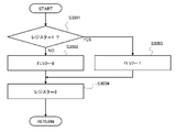
- the flowchart of FIG. 5 shows the setting processing of the low voltage determination flag FLV2, which is performed by an interrupt in step S2009.
- the first microcomputer 101A determines the interrupt factor in step S3001. If zero is set in the interrupt factor register, that is, if the interrupt is based on the determination that the voltage at the output end of the second power connector 102B has returned to the normal voltage, the first microcomputer 101A proceeds to step S3002. to reset the low voltage determination flag FLV2 of the second control system 100B to zero.
- the first microcomputer 101A proceeds to step S3003. , and raises the low voltage determination flag FLV2 of the second control system 100B to 1. After the processing in step S3002 or step S3003, the first microcomputer 101A advances to step S3004 and resets the interrupt factor register to zero.
- the first microcomputer 101A sets the low voltage determination flag FLV2 to 1 when it determines that the voltage at the output end of the second power connector 102B monitored using the first voltage monitoring line 111A is lower than the normal voltage.
- the low voltage determination flag FLV2 is reset to zero.
- the first microcomputer 101A determines that the reset state of the second microcomputer 101B due to the low voltage has been determined, and proceeds to step S2010. It is determined whether or not the voltage has returned to normal, communication with the second microcomputer 101B is normal, and the output signal of the second torque sensor 104B is normal.
- the second microcomputer 101B is activated. Then, when the second microcomputer 101B is activated, the first microcomputer 101A becomes able to communicate normally with the second microcomputer 101B and can normally acquire the output signal of the second torque sensor 104B. .
- step S2010 determines in step S2010 that the normal state has not been restored, it terminates this routine, and if it determines that the normal state has been restored, the process advances to step S2011.
- step S2011 the first microcomputer 101A executes addition processing (C5 ⁇ C5+1) of the value of the normal counter C5.
- the normal counter C5 has a value equal to or greater than zero, and its initial value is zero.
- the first microcomputer 101A advances to step S2012 to determine whether or not the value of the normality counter C5 is equal to or greater than a predetermined value THC5 (THC5>0). Then, if the value of the normality counter C5 is less than the predetermined value THC5 and the predetermined time has not passed after returning to the normal state, the first microcomputer 101A terminates this routine as it is.
- step S2013 the first microcomputer 101A clears all of the abnormality counter C3, the normal counter C4, the normal counter C5, and the failure determination flag FM2, and further generates an interrupt for processing to set the low voltage determination flag FLV2. . That is, the first microcomputer 101A cancels determination of the voltage fluctuation when the voltage supplied to the second microcomputer 101B returns to normal and continues for a predetermined period.
- the voltage at the output end of the first power connector 102A is lower than the normal voltage in the second voltage fluctuation determining section 101B2 of the second microcomputer 101B, similar to the first voltage fluctuation determining section 101A2 of the first microcomputer 101A. is low, the communication with the first microcomputer 101A is abnormal, and the output signal of the first torque sensor 104A is abnormal, the first microcomputer 101A is in the reset state due to the low voltage.
- the reset state continues for a predetermined period, the reset state is determined.
- FIG. 6 shows the diagnosis by the second microcomputer 101B, more specifically, the second abnormality determination unit 101B1, when the first microcomputer 101A is reset due to a failure of the first power supply IC 103A or the first microcomputer 101A. It is a time chart which shows a state. At time t1, when an abnormality occurs in the first power supply IC 103A or the first microcomputer 101A, the first microcomputer 101A enters a reset state even if the voltage at the output terminal of the first power supply connector 102A is a normal voltage.
- the second microcomputer 101B uses the second voltage monitoring line 111B to detect that the voltage at the output terminal of the first power connector 102A is normal.
- the second microcomputer 101B detects that the voltage at the output terminal of the first power connector 102A is normal, that communication with the first microcomputer 101A is abnormal, and that the first torque sensor It is determined that the abnormality determination condition that the output signal of 104A is abnormal is satisfied. Then, the second microcomputer 101B starts addition processing of the abnormality counter C1 from time t1 to measure the duration of time satisfying the abnormality determination condition, and when the duration reaches the predetermined time at time t2, , determine the reset state of the first microcomputer 101A due to an abnormality in the first power supply IC 103A or the first microcomputer 101A.
- FIG. 7 shows the second microcomputer 101B when the voltage at the output terminal of the first power connector 102A becomes lower than the normal voltage due to disconnection of the first power connector 102A, and the first microcomputer 101A enters the reset state. More specifically, it is a time chart showing a state of diagnosis by a second voltage fluctuation determining section 101B2. At time t11, when the first power connector 102A is disconnected, the voltage at the output end of the first power connector 102A drops, and the first microcomputer 101A enters a reset state.
- the second microcomputer 101B uses the second voltage monitoring line 111B to detect that the voltage at the output end of the first power connector 102A is lower than the normal voltage.
- the second microcomputer 101B detects that the voltage at the output terminal of the first power connector 102A is abnormal, the communication with the first microcomputer 101A is abnormal, and the first torque sensor It is determined that the abnormality determination condition that the output signal of 104A is abnormal, in other words, the reset determination condition due to voltage fluctuation is satisfied. Then, the second microcomputer 101B starts addition processing of the abnormality counter C3 from time t11, thereby measuring the duration of time satisfying the abnormality determination condition, and when the duration reaches the predetermined time at time t12. , determines the reset state of the first microcomputer 101A due to the fluctuation of the voltage supplied to the first microcomputer 101A.
- FIG. 8 shows the second microcomputer 101B when the voltage at the output terminal of the first power connector 102A becomes lower than the normal voltage due to the voltage drop of the battery 300 and the first microcomputer 101A enters the reset state.
- 4 is a time chart showing how the second voltage fluctuation determination unit 101B2 diagnoses. Note that the time chart of FIG. 8 shows the operation of the second microcomputer 101B when the voltage drop of the battery 300 causes the first microcomputer 101A to enter the reset state, while the second microcomputer 101B does not enter the reset state.
- the second microcomputer 101B uses the second voltage monitoring line 111B to detect that the voltage at the output end of the first power connector 102A is lower than the normal voltage. That is, at time t21, the second microcomputer 101B is in an abnormal state in which the voltage at the output terminal of the first power connector 102A is low, the communication with the first microcomputer 101A is abnormal, and the first It is determined that the abnormality determination condition that the output signal of the torque sensor 104A is abnormal, that is, the reset determination condition based on voltage fluctuation is satisfied. The second microcomputer 101B starts addition processing of the abnormality counter C3 at time t21 to measure the duration for which the abnormality determination condition is satisfied. The reset state of the first microcomputer 101A due to fluctuations in the voltage supplied to the microcomputer 101A is determined.
- the first microcomputer 101A It is activated at time t23.
- the second microcomputer 101B can communicate normally with the first microcomputer 101A, and the output signal of the first torque sensor 104A returns to normal.
- the second microcomputer 101B confirms that the voltage at the output end of the first power connector 102A is normal, communication with the first microcomputer 101A is normal, and the first torque sensor 104A
- the output signal is determined to be normal
- the addition processing of the normality counter C5 is started.
- the second microcomputer 101B clears the confirmation flag of the reset due to the voltage fluctuation, and confirms the return to the normal state. .
- the first microcomputer 101A and the second microcomputer 101B can distinguish between a reset due to an abnormality in the partner's power supply IC and a reset due to disconnection of the partner's power supply connector.
- the control of the steering assist force in electric power steering 200 can be switched.
- a mode of control of the steering assist force when one of the first microcomputer 101A and the second microcomputer 101B is in the reset state will be described below.
- FIG. 9 is a time chart showing control of the steering assist force when the first microcomputer 101A diagnoses a reset state of the second microcomputer 101B due to an abnormality in the second power supply IC 103B or the second microcomputer 101B.
- the first microcomputer 101A confirms at time t31 that the second microcomputer 101B is reset due to an abnormality in the second power supply IC 103B or the second microcomputer 101B, the first microcomputer 101A supplies power to the first winding set 210A. to 100% or less of normal power.
- the first microcomputer 101A can reduce the power supplied to the first winding set 210A to less than 100% of normal power, eg, 0%-50%. In this way, when an abnormality occurs in the second power supply IC 103B or the second microcomputer 101B, the power supplied to the first winding set 210A is reduced below the normal power to intentionally reduce the steering assist force. Thus, even a slight steering operation can make the driver aware that the generation of the steering assist force by the second control system 100B is stopped. However, the first microcomputer 101A can maintain the power supplied to the first winding set 210A at 100% of normal power or power exceeding 100%.
- the second microcomputer 101B reduces the power supplied to the second winding set 210B to 0% of the normal power, that is, the second The supply of electricity to the winding set 210B is kept stopped. As a result, even when the second microcomputer 101B repeats resetting, it is possible to prevent the steering assist force from vibrating.
- the first microcomputer 101A can gradually reduce the power supplied to the first winding set 210A from 100% or less of the normal power.
- the first microcomputer 101A can, for example, gradually reduce the power supplied to the first winding set 210A from 100% of the normal power, and reduce the power supplied to the first winding set 210A to the normal power. It can be stepped down from 100% to a setpoint below 100% and then tapered off from said setpoint.
- the second microcomputer 101B diagnoses that the first power supply IC 103A or the first microcomputer 101A is in a reset state due to an abnormality in the first power supply IC 103A or the first microcomputer 101A, the power supplied to the second winding set 210B is reduced to 100% of the normal power. % or less, for example, 0%-50%. Also, the second microcomputer 101B can gradually reduce the power supplied to the second winding set 210B from 100% or less of the normal power.
- FIG. 10 shows the control of the steering assist force when the first microcomputer 101A diagnoses the voltage abnormality at the output end of the second power connector 102B, in other words, the reset state of the second microcomputer 101B due to the voltage fluctuation.
- the second microcomputer 101B which is in the reset state due to the voltage abnormality, in other words, the voltage fluctuation, stops energizing the second winding set 210B.
- the first microcomputer 101A which maintains the activated state, normally
- the second microcomputer 101B also controls the power supplied to the first winding set 210A in the same manner as when normally activated.
- the first microcomputer 101A reduces the power supplied to the first winding set 210A to 100% of the normal power. If maintained, it is possible to avoid the sudden stop of generation of the steering assist force. Then, when the voltage at the output terminal of the second power connector 102B, in other words, the voltage supplied to the second microcomputer 101B returns to normal and continues for a predetermined period, the first microcomputer 101A cancels determination of the voltage fluctuation. .
- the second microcomputer 101B performs an initial diagnosis between time t42 and time t43. After that, the second microcomputer 101B gradually increases the power supplied to the second winding set 210B to 100% of the normal power between time t43 and time t44 to return the steering assist force to the normal level.
- the vehicle-mounted equipment is controlled by a redundant electronic control device including the first microcomputer 101A and the second microcomputer 101B, and is not limited to the electric power steering 200. Further, in the on-vehicle equipment, the controlled object controlled by the first microcomputer 101A and the second microcomputer 101B is not limited to the electric motor. Further, the system may include a first battery and a second battery, connect the first battery and the first power connector 102A, and connect the second battery and the second power connector 102B.
- first and second sensors used by the first microcomputer 101A and the second microcomputer 101B for diagnosis processing for determining abnormality and determining voltage fluctuation are limited to the first torque sensor 104A and the second torque sensor 104B. is not.
- first microcomputer 101A and second microcomputer 101B issue a transmission request Based on the detection signals from the first rotation angle sensor and the second rotation angle sensor in response to the command signal of (1), it is possible to carry out diagnostic processing for confirming the abnormality and confirming the voltage fluctuation.
- the first microcomputer 101A and the second microcomputer 101B are: Based on the detection signals from the first steering angle sensor and the second steering angle sensor in response to the command signal of the transmission request, it is possible to carry out diagnostic processing for confirming the abnormality and confirming the voltage fluctuation.
- the first microcomputer 101A and the second microcomputer 101B receive a control command for a predriver that controls the inverter from the counterpart microcomputer as information for determining whether the counterpart microcomputer is in a reset state. can be obtained.
- the first microcomputer 101A acquires from the second microcomputer 101B a control command for the second pre-driver 105B that controls the second inverter 106B connected to the second winding set 210B
- the computer 101B is configured to acquire from the first microcomputer 101A a control command for the first pre-driver 105A that controls the first inverter 106A connected to the first winding set 210A.
- the first microcomputer 101A determines the reset state of the second microcomputer 101B based on the abnormality of the control command of the second pre-driver 105B
- the second microcomputer 101B determines the abnormality of the control command of the first pre-driver 105A. determines the reset state of the first microcomputer 101A.
- the first microcomputer 101A and the second microcomputer 101B activate and reset the counterpart microcomputer based on at least one of the state of the control command of the predriver, the state of the sensor, and the state of communication between the microcomputers. It is possible to perform diagnostic processing for determination of abnormality and determination of voltage fluctuation.
- the first microcomputer 101A and the second microcomputer 101B are connected to the in-vehicle network 400, the first microcomputer 101A grasps the information acquisition status via the in-vehicle network 400 of the second microcomputer 101B, The second microcomputer 101B can grasp the information acquisition status via the in-vehicle network 400 of the first microcomputer 101A. Then, the first microcomputer 101A and the second microcomputer 101B determine whether the other microcomputer is in a reset state based on whether the information acquisition status of the other microcomputer via the in-vehicle network 400 is normal. can determine whether
- the first microcomputer 101A and the second microcomputer 101B are based on at least one of the information acquisition status via the in-vehicle network 400, the pre-driver control command status, the sensor status, and the communication status between the microcomputers. , the operating state of the counterpart microcomputer can be determined, and diagnosis processing for determining abnormality and determining voltage fluctuation can be performed.
- the first microcomputer 101A and the second microcomputer 101B provide information and signals that differ depending on whether the microcomputer of the other party is in the activated state or the reset state, and the output of the power connector of the other party. Based on the terminal voltage, it is possible to carry out diagnostic processing for confirming abnormality and confirming voltage fluctuation.
- the microcomputer that is activated will return to its own winding set.
- the microcomputer that maintains the activated state can gradually increase the power supplied when increasing the power supplied to the winding set of its own system to a value exceeding 100% of the normal value.
- Second inverter 111A... First voltage monitoring line, 111B... Second voltage monitoring line, 200... Electric power steering (equipment mounted on vehicle), 210... Electric motor, 210A... First winding set, 210B...Second winding set, 300...Battery (power supply), 400...In-vehicle network
Landscapes
- Engineering & Computer Science (AREA)
- Power Engineering (AREA)
- Chemical & Material Sciences (AREA)
- Combustion & Propulsion (AREA)
- Transportation (AREA)
- Mechanical Engineering (AREA)
- Computer Networks & Wireless Communication (AREA)
- Signal Processing (AREA)
- Control Of Electric Motors In General (AREA)
- Power Sources (AREA)
- Power Steering Mechanism (AREA)
Priority Applications (4)
| Application Number | Priority Date | Filing Date | Title |
|---|---|---|---|
| US18/263,222 US12355383B2 (en) | 2021-01-29 | 2021-12-29 | Electronic control device for vehicle-mounted equipment |
| JP2022578199A JP7526292B2 (ja) | 2021-01-29 | 2021-12-29 | 車両搭載機器の電子制御装置 |
| CN202180091989.XA CN116802085A (zh) | 2021-01-29 | 2021-12-29 | 车载设备的电子控制装置 |
| DE112021006980.2T DE112021006980T5 (de) | 2021-01-29 | 2021-12-29 | Elektronische Steuervorrichtung für fahrzeugmontierte Ausrüstung |
Applications Claiming Priority (2)
| Application Number | Priority Date | Filing Date | Title |
|---|---|---|---|
| JP2021012947 | 2021-01-29 | ||
| JP2021-012947 | 2021-06-16 |
Publications (1)
| Publication Number | Publication Date |
|---|---|
| WO2022163302A1 true WO2022163302A1 (ja) | 2022-08-04 |
Family
ID=82654514
Family Applications (1)
| Application Number | Title | Priority Date | Filing Date |
|---|---|---|---|
| PCT/JP2021/049020 Ceased WO2022163302A1 (ja) | 2021-01-29 | 2021-12-29 | 車両搭載機器の電子制御装置 |
Country Status (5)
| Country | Link |
|---|---|
| US (1) | US12355383B2 (https=) |
| JP (1) | JP7526292B2 (https=) |
| CN (1) | CN116802085A (https=) |
| DE (1) | DE112021006980T5 (https=) |
| WO (1) | WO2022163302A1 (https=) |
Cited By (1)
| Publication number | Priority date | Publication date | Assignee | Title |
|---|---|---|---|---|
| US20240322734A1 (en) * | 2021-01-29 | 2024-09-26 | Hitachi Astemo, Ltd. | Electronic control device for vehicle-mounted equipment |
Families Citing this family (1)
| Publication number | Priority date | Publication date | Assignee | Title |
|---|---|---|---|---|
| JP2024002616A (ja) * | 2022-06-24 | 2024-01-11 | 株式会社ジェイテクト | 電源装置 |
Citations (5)
| Publication number | Priority date | Publication date | Assignee | Title |
|---|---|---|---|---|
| JPH10297395A (ja) * | 1997-04-22 | 1998-11-10 | Toyota Motor Corp | 電子制御装置 |
| JP2015081013A (ja) * | 2013-10-23 | 2015-04-27 | 三菱電機株式会社 | 電動パワーステアリング制御装置 |
| JP2017163776A (ja) * | 2016-03-11 | 2017-09-14 | 日立オートモティブシステムズ株式会社 | 制御装置及び複数の演算処理装置における異常通知方法 |
| WO2018173561A1 (ja) * | 2017-03-23 | 2018-09-27 | 日立オートモティブシステムズ株式会社 | 車両制御装置 |
| JP2019004682A (ja) * | 2017-02-28 | 2019-01-10 | 株式会社デンソー | モータ制御装置、モータ駆動システム、及び、モータ制御方法 |
Family Cites Families (43)
| Publication number | Priority date | Publication date | Assignee | Title |
|---|---|---|---|---|
| JP3646621B2 (ja) * | 2000-04-28 | 2005-05-11 | 株式会社デンソー | 複数電源回路を備えた電子制御装置 |
| JP2006268107A (ja) * | 2005-03-22 | 2006-10-05 | Denso Corp | 電子制御装置 |
| JP4408921B2 (ja) * | 2007-08-22 | 2010-02-03 | 株式会社デンソー | 電子機器 |
| JP4518150B2 (ja) * | 2008-01-11 | 2010-08-04 | 株式会社デンソー | 車両用電子制御装置 |
| JP2009181178A (ja) * | 2008-01-29 | 2009-08-13 | Denso Corp | 電子制御装置 |
| JP4525762B2 (ja) * | 2008-02-04 | 2010-08-18 | 株式会社デンソー | 車両用電子制御装置 |
| JP2011195089A (ja) * | 2010-03-23 | 2011-10-06 | Jtekt Corp | 電動パワーステアリング装置 |
| JP5195888B2 (ja) * | 2010-06-24 | 2013-05-15 | 株式会社デンソー | 電動機駆動装置、および、これを用いた電動パワーステアリング装置 |
| JP5246230B2 (ja) * | 2010-09-13 | 2013-07-24 | 株式会社デンソー | 車両用電子制御装置 |
| JP5116825B2 (ja) * | 2010-10-26 | 2013-01-09 | 三菱電機株式会社 | 電子制御装置 |
| JP5817935B2 (ja) * | 2012-09-24 | 2015-11-18 | 日産自動車株式会社 | 電動車両の制御装置 |
| JP5898104B2 (ja) * | 2013-02-13 | 2016-04-06 | 日立オートモティブシステムズステアリング株式会社 | 電源電圧監視回路、車両のセンサ回路およびパワーステアリング装置 |
| JP5831523B2 (ja) * | 2013-10-09 | 2015-12-09 | 株式会社デンソー | 電子制御装置 |
| JP6302727B2 (ja) * | 2014-04-10 | 2018-03-28 | 日立オートモティブシステムズ株式会社 | 電動モータの制御装置 |
| JP5968501B1 (ja) * | 2015-06-01 | 2016-08-10 | 三菱電機株式会社 | 車載電子制御装置 |
| JP6579006B2 (ja) * | 2016-03-17 | 2019-09-25 | 株式会社デンソー | センサ装置、および、これを用いた電動パワーステアリング装置 |
| US10328972B2 (en) * | 2016-04-06 | 2019-06-25 | Denso Corporation | Rotation detecting apparatus and electric power steering apparatus using the same |
| JP7035317B2 (ja) * | 2016-04-06 | 2022-03-15 | 株式会社デンソー | 回転検出装置、および、これを用いた電動パワーステアリング装置 |
| JP6642278B2 (ja) * | 2016-05-27 | 2020-02-05 | 株式会社デンソー | 回転電機制御装置、および、これを用いた電動パワーステアリング装置 |
| JP7024226B2 (ja) * | 2016-07-11 | 2022-02-24 | 株式会社デンソー | モータ制御装置、モータ駆動システム、及び、モータ制御方法 |
| US10668945B2 (en) * | 2016-07-11 | 2020-06-02 | Denso Corporation | Motor control apparatus, motor drive system, and motor control method |
| JP6801287B2 (ja) * | 2016-08-10 | 2020-12-16 | 株式会社ジェイテクト | モータ制御装置 |
| JP6759858B2 (ja) * | 2016-08-26 | 2020-09-23 | 株式会社デンソー | センサ装置 |
| JP6714088B2 (ja) * | 2016-09-15 | 2020-06-24 | 日立オートモティブシステムズ株式会社 | 車両搭載機器のアクチュエータ及びパワーステアリング装置 |
| JP6939441B2 (ja) * | 2017-11-08 | 2021-09-22 | トヨタ自動車株式会社 | 制御装置 |
| JP6798476B2 (ja) * | 2017-11-30 | 2020-12-09 | 株式会社デンソー | モータ制御装置、モータ駆動システム、及び、モータ制御方法 |
| JP6988492B2 (ja) * | 2018-01-11 | 2022-01-05 | 株式会社デンソー | 電動パワーステアリング装置 |
| US11529990B2 (en) * | 2018-03-20 | 2022-12-20 | Denso Corporation | Signal control apparatus and electric power steering apparatus using same |
| JP7147525B2 (ja) * | 2018-06-08 | 2022-10-05 | 住友電装株式会社 | 通信装置及び制御方法 |
| JP7155763B2 (ja) * | 2018-09-03 | 2022-10-19 | 株式会社ジェイテクト | 車両制御装置 |
| JP7172306B2 (ja) * | 2018-09-03 | 2022-11-16 | 株式会社ジェイテクト | 車両制御装置 |
| KR102582285B1 (ko) * | 2018-10-16 | 2023-09-26 | 에이치엘만도 주식회사 | 조향 제어 장치, 조향 모터, 조향 장치 및 조향 제어 방법 |
| JP7236248B2 (ja) * | 2018-10-29 | 2023-03-09 | 株式会社ジェイテクト | モータ制御装置 |
| JP7225689B2 (ja) * | 2018-11-05 | 2023-02-21 | 株式会社ジェイテクト | モータ制御装置 |
| EP3663164B1 (en) * | 2018-12-03 | 2022-04-27 | Jtekt Corporation | Steering control device |
| JP7271943B2 (ja) * | 2018-12-25 | 2023-05-12 | 株式会社ジェイテクト | 操舵制御装置 |
| US11479291B2 (en) * | 2018-12-27 | 2022-10-25 | Denso Corporation | Control apparatus |
| US11820444B2 (en) * | 2019-01-18 | 2023-11-21 | Hitachi Astemo, Ltd. | Control device for vehicle-mounted equipment |
| JP7137496B2 (ja) * | 2019-03-04 | 2022-09-14 | 日立Astemo株式会社 | 電動モータの駆動制御装置 |
| JP7315364B2 (ja) * | 2019-04-17 | 2023-07-26 | トヨタ自動車株式会社 | 操舵制御システム |
| JP7540920B2 (ja) * | 2020-09-07 | 2024-08-27 | 株式会社ジェイテクト | モータの制御装置 |
| DE112021006980T5 (de) * | 2021-01-29 | 2023-12-28 | Hitachi Astemo, Ltd. | Elektronische Steuervorrichtung für fahrzeugmontierte Ausrüstung |
| JP7388410B2 (ja) * | 2021-07-28 | 2023-11-29 | トヨタ自動車株式会社 | ステアリングシステム |
-
2021
- 2021-12-29 DE DE112021006980.2T patent/DE112021006980T5/de active Pending
- 2021-12-29 WO PCT/JP2021/049020 patent/WO2022163302A1/ja not_active Ceased
- 2021-12-29 US US18/263,222 patent/US12355383B2/en active Active
- 2021-12-29 CN CN202180091989.XA patent/CN116802085A/zh active Pending
- 2021-12-29 JP JP2022578199A patent/JP7526292B2/ja active Active
Patent Citations (5)
| Publication number | Priority date | Publication date | Assignee | Title |
|---|---|---|---|---|
| JPH10297395A (ja) * | 1997-04-22 | 1998-11-10 | Toyota Motor Corp | 電子制御装置 |
| JP2015081013A (ja) * | 2013-10-23 | 2015-04-27 | 三菱電機株式会社 | 電動パワーステアリング制御装置 |
| JP2017163776A (ja) * | 2016-03-11 | 2017-09-14 | 日立オートモティブシステムズ株式会社 | 制御装置及び複数の演算処理装置における異常通知方法 |
| JP2019004682A (ja) * | 2017-02-28 | 2019-01-10 | 株式会社デンソー | モータ制御装置、モータ駆動システム、及び、モータ制御方法 |
| WO2018173561A1 (ja) * | 2017-03-23 | 2018-09-27 | 日立オートモティブシステムズ株式会社 | 車両制御装置 |
Cited By (2)
| Publication number | Priority date | Publication date | Assignee | Title |
|---|---|---|---|---|
| US20240322734A1 (en) * | 2021-01-29 | 2024-09-26 | Hitachi Astemo, Ltd. | Electronic control device for vehicle-mounted equipment |
| US12355383B2 (en) * | 2021-01-29 | 2025-07-08 | Hitachi Astemo, Ltd. | Electronic control device for vehicle-mounted equipment |
Also Published As
| Publication number | Publication date |
|---|---|
| CN116802085A (zh) | 2023-09-22 |
| JP7526292B2 (ja) | 2024-07-31 |
| JPWO2022163302A1 (https=) | 2022-08-04 |
| US20240322734A1 (en) | 2024-09-26 |
| DE112021006980T5 (de) | 2023-12-28 |
| US12355383B2 (en) | 2025-07-08 |
Similar Documents
| Publication | Publication Date | Title |
|---|---|---|
| CN112351933B (zh) | 具有冗余配置的控制单元的机动车辆转向系统 | |
| US6687590B2 (en) | Electric power steering apparatus | |
| US11643095B2 (en) | Electronic control device, control system, and reset determination method | |
| WO2022163302A1 (ja) | 車両搭載機器の電子制御装置 | |
| EP2476590B1 (en) | Power supply status diagnostic method and device | |
| JP6894041B2 (ja) | 車両搭載機器の制御装置 | |
| US11770089B2 (en) | Rotary electric machine control device | |
| CN113371057B (zh) | 马达控制装置 | |
| JP7005792B2 (ja) | 車両搭載機器の制御装置 | |
| JP3527071B2 (ja) | 電気自動車の制御装置 | |
| JP7225689B2 (ja) | モータ制御装置 | |
| US8004221B2 (en) | Inverter system for vehicle-mounted air conditioner | |
| WO2019049731A1 (ja) | パワーステアリング装置の制御装置 | |
| CN115675622A (zh) | 转向系统 | |
| EP3653996B1 (en) | Sensor information output apparatus and vehicle control apparatus | |
| US12587029B2 (en) | Power supply apparatus | |
| JP2019041171A (ja) | 車両の制御装置 | |
| EP1650863A1 (en) | Electric power steering apparatus and electricity supply system | |
| JP2002514380A (ja) | 駆動部用の安全装置 | |
| JP2005193834A (ja) | 電動パワーステアリング装置の制御装置 | |
| WO2021117636A1 (ja) | 電動モータの駆動制御装置 | |
| CN113497574A (zh) | 电机控制装置 | |
| JP2021054304A (ja) | 電動パワーステアリング制御装置 | |
| JPH1118202A (ja) | 車両用制御装置 | |
| JPH10164702A (ja) | 電気自動車のモーター駆動制御装置 |
Legal Events
| Date | Code | Title | Description |
|---|---|---|---|
| 121 | Ep: the epo has been informed by wipo that ep was designated in this application |
Ref document number: 21923305 Country of ref document: EP Kind code of ref document: A1 |
|
| ENP | Entry into the national phase |
Ref document number: 2022578199 Country of ref document: JP Kind code of ref document: A |
|
| WWE | Wipo information: entry into national phase |
Ref document number: 202180091989.X Country of ref document: CN |
|
| WWE | Wipo information: entry into national phase |
Ref document number: 18263222 Country of ref document: US |
|
| WWE | Wipo information: entry into national phase |
Ref document number: 112021006980 Country of ref document: DE |
|
| 122 | Ep: pct application non-entry in european phase |
Ref document number: 21923305 Country of ref document: EP Kind code of ref document: A1 |
|
| WWG | Wipo information: grant in national office |
Ref document number: 18263222 Country of ref document: US |